EP2283799A2 - Mécanisme lateral et d'extrémité de frein/direction pour brancard - Google Patents
Mécanisme lateral et d'extrémité de frein/direction pour brancard Download PDFInfo
- Publication number
- EP2283799A2 EP2283799A2 EP10191861A EP10191861A EP2283799A2 EP 2283799 A2 EP2283799 A2 EP 2283799A2 EP 10191861 A EP10191861 A EP 10191861A EP 10191861 A EP10191861 A EP 10191861A EP 2283799 A2 EP2283799 A2 EP 2283799A2
- Authority
- EP
- European Patent Office
- Prior art keywords
- brake
- pedal
- patient support
- support apparatus
- wheel
- Prior art date
- Legal status (The legal status is an assumption and is not a legal conclusion. Google has not performed a legal analysis and makes no representation as to the accuracy of the status listed.)
- Granted
Links
- 230000007246 mechanism Effects 0.000 title abstract description 28
- 230000000994 depressogenic effect Effects 0.000 description 5
- 230000007935 neutral effect Effects 0.000 description 5
- 230000008901 benefit Effects 0.000 description 3
- 230000000712 assembly Effects 0.000 description 2
- 238000000429 assembly Methods 0.000 description 2
- 238000010276 construction Methods 0.000 description 2
- 230000004048 modification Effects 0.000 description 2
- 238000012986 modification Methods 0.000 description 2
- 230000000881 depressing effect Effects 0.000 description 1
- 239000002184 metal Substances 0.000 description 1
- 230000000717 retained effect Effects 0.000 description 1
- 230000001360 synchronised effect Effects 0.000 description 1
Images


Classifications
-
- B—PERFORMING OPERATIONS; TRANSPORTING
- B60—VEHICLES IN GENERAL
- B60B—VEHICLE WHEELS; CASTORS; AXLES FOR WHEELS OR CASTORS; INCREASING WHEEL ADHESION
- B60B33/00—Castors in general; Anti-clogging castors
- B60B33/0002—Castors in general; Anti-clogging castors assembling to the object, e.g. furniture
- B60B33/0015—Castors in general; Anti-clogging castors assembling to the object, e.g. furniture characterised by adaptations made to castor
- B60B33/0021—Castors in general; Anti-clogging castors assembling to the object, e.g. furniture characterised by adaptations made to castor in the form of a mounting pin
-
- A—HUMAN NECESSITIES
- A61—MEDICAL OR VETERINARY SCIENCE; HYGIENE
- A61G—TRANSPORT, PERSONAL CONVEYANCES, OR ACCOMMODATION SPECIALLY ADAPTED FOR PATIENTS OR DISABLED PERSONS; OPERATING TABLES OR CHAIRS; CHAIRS FOR DENTISTRY; FUNERAL DEVICES
- A61G1/00—Stretchers
- A61G1/02—Stretchers with wheels
- A61G1/0206—Stretchers with wheels characterised by the number of supporting wheels if stretcher is extended
- A61G1/0225—Stretchers with wheels characterised by the number of supporting wheels if stretcher is extended other configuration, e.g. odd number of wheels
-
- A—HUMAN NECESSITIES
- A61—MEDICAL OR VETERINARY SCIENCE; HYGIENE
- A61G—TRANSPORT, PERSONAL CONVEYANCES, OR ACCOMMODATION SPECIALLY ADAPTED FOR PATIENTS OR DISABLED PERSONS; OPERATING TABLES OR CHAIRS; CHAIRS FOR DENTISTRY; FUNERAL DEVICES
- A61G1/00—Stretchers
- A61G1/02—Stretchers with wheels
- A61G1/0237—Stretchers with wheels having at least one swivelling wheel, e.g. castors
-
- A—HUMAN NECESSITIES
- A61—MEDICAL OR VETERINARY SCIENCE; HYGIENE
- A61G—TRANSPORT, PERSONAL CONVEYANCES, OR ACCOMMODATION SPECIALLY ADAPTED FOR PATIENTS OR DISABLED PERSONS; OPERATING TABLES OR CHAIRS; CHAIRS FOR DENTISTRY; FUNERAL DEVICES
- A61G1/00—Stretchers
- A61G1/02—Stretchers with wheels
- A61G1/025—Stretchers with wheels having auxiliary wheels, e.g. wheels not touching the ground in extended position
- A61G1/0268—Stretchers with wheels having auxiliary wheels, e.g. wheels not touching the ground in extended position having deployable or retractable wheels
-
- A—HUMAN NECESSITIES
- A61—MEDICAL OR VETERINARY SCIENCE; HYGIENE
- A61G—TRANSPORT, PERSONAL CONVEYANCES, OR ACCOMMODATION SPECIALLY ADAPTED FOR PATIENTS OR DISABLED PERSONS; OPERATING TABLES OR CHAIRS; CHAIRS FOR DENTISTRY; FUNERAL DEVICES
- A61G1/00—Stretchers
- A61G1/02—Stretchers with wheels
- A61G1/0287—Stretchers with wheels having brakes, e.g. slowing down and/or holding
-
- A—HUMAN NECESSITIES
- A61—MEDICAL OR VETERINARY SCIENCE; HYGIENE
- A61G—TRANSPORT, PERSONAL CONVEYANCES, OR ACCOMMODATION SPECIALLY ADAPTED FOR PATIENTS OR DISABLED PERSONS; OPERATING TABLES OR CHAIRS; CHAIRS FOR DENTISTRY; FUNERAL DEVICES
- A61G7/00—Beds specially adapted for nursing; Devices for lifting patients or disabled persons
- A61G7/05—Parts, details or accessories of beds
- A61G7/0528—Steering or braking devices for castor wheels
-
- B—PERFORMING OPERATIONS; TRANSPORTING
- B60—VEHICLES IN GENERAL
- B60B—VEHICLE WHEELS; CASTORS; AXLES FOR WHEELS OR CASTORS; INCREASING WHEEL ADHESION
- B60B33/00—Castors in general; Anti-clogging castors
- B60B33/0036—Castors in general; Anti-clogging castors characterised by type of wheels
- B60B33/0039—Single wheels
-
- B—PERFORMING OPERATIONS; TRANSPORTING
- B60—VEHICLES IN GENERAL
- B60B—VEHICLE WHEELS; CASTORS; AXLES FOR WHEELS OR CASTORS; INCREASING WHEEL ADHESION
- B60B33/00—Castors in general; Anti-clogging castors
- B60B33/0047—Castors in general; Anti-clogging castors characterised by details of the rolling axle
- B60B33/0049—Castors in general; Anti-clogging castors characterised by details of the rolling axle the rolling axle being horizontal
-
- B—PERFORMING OPERATIONS; TRANSPORTING
- B60—VEHICLES IN GENERAL
- B60B—VEHICLE WHEELS; CASTORS; AXLES FOR WHEELS OR CASTORS; INCREASING WHEEL ADHESION
- B60B33/00—Castors in general; Anti-clogging castors
- B60B33/0047—Castors in general; Anti-clogging castors characterised by details of the rolling axle
- B60B33/0057—Castors in general; Anti-clogging castors characterised by details of the rolling axle the rolling axle being offset from swivel axis
-
- B—PERFORMING OPERATIONS; TRANSPORTING
- B60—VEHICLES IN GENERAL
- B60B—VEHICLE WHEELS; CASTORS; AXLES FOR WHEELS OR CASTORS; INCREASING WHEEL ADHESION
- B60B33/00—Castors in general; Anti-clogging castors
- B60B33/006—Castors in general; Anti-clogging castors characterised by details of the swivel mechanism
- B60B33/0065—Castors in general; Anti-clogging castors characterised by details of the swivel mechanism characterised by details of the swivel axis
- B60B33/0068—Castors in general; Anti-clogging castors characterised by details of the swivel mechanism characterised by details of the swivel axis the swivel axis being vertical
-
- B—PERFORMING OPERATIONS; TRANSPORTING
- B60—VEHICLES IN GENERAL
- B60B—VEHICLE WHEELS; CASTORS; AXLES FOR WHEELS OR CASTORS; INCREASING WHEEL ADHESION
- B60B33/00—Castors in general; Anti-clogging castors
- B60B33/006—Castors in general; Anti-clogging castors characterised by details of the swivel mechanism
- B60B33/0065—Castors in general; Anti-clogging castors characterised by details of the swivel mechanism characterised by details of the swivel axis
- B60B33/0073—Castors in general; Anti-clogging castors characterised by details of the swivel mechanism characterised by details of the swivel axis the swivel axis being symmetrical to wheel or wheels
-
- B—PERFORMING OPERATIONS; TRANSPORTING
- B60—VEHICLES IN GENERAL
- B60B—VEHICLE WHEELS; CASTORS; AXLES FOR WHEELS OR CASTORS; INCREASING WHEEL ADHESION
- B60B33/00—Castors in general; Anti-clogging castors
- B60B33/0078—Castors in general; Anti-clogging castors characterised by details of the wheel braking mechanism
- B60B33/0081—Castors in general; Anti-clogging castors characterised by details of the wheel braking mechanism acting on tire tread
-
- B—PERFORMING OPERATIONS; TRANSPORTING
- B60—VEHICLES IN GENERAL
- B60B—VEHICLE WHEELS; CASTORS; AXLES FOR WHEELS OR CASTORS; INCREASING WHEEL ADHESION
- B60B33/00—Castors in general; Anti-clogging castors
- B60B33/0078—Castors in general; Anti-clogging castors characterised by details of the wheel braking mechanism
- B60B33/0092—Castors in general; Anti-clogging castors characterised by details of the wheel braking mechanism actuated remotely, e.g. by cable or electrically
-
- B—PERFORMING OPERATIONS; TRANSPORTING
- B60—VEHICLES IN GENERAL
- B60B—VEHICLE WHEELS; CASTORS; AXLES FOR WHEELS OR CASTORS; INCREASING WHEEL ADHESION
- B60B33/00—Castors in general; Anti-clogging castors
- B60B33/02—Castors in general; Anti-clogging castors with disengageable swivel action, i.e. comprising a swivel locking mechanism
- B60B33/021—Castors in general; Anti-clogging castors with disengageable swivel action, i.e. comprising a swivel locking mechanism combined with braking of castor wheel
-
- B—PERFORMING OPERATIONS; TRANSPORTING
- B60—VEHICLES IN GENERAL
- B60B—VEHICLE WHEELS; CASTORS; AXLES FOR WHEELS OR CASTORS; INCREASING WHEEL ADHESION
- B60B33/00—Castors in general; Anti-clogging castors
- B60B33/04—Castors in general; Anti-clogging castors adjustable, e.g. in height; linearly shifting castors
- B60B33/06—Castors in general; Anti-clogging castors adjustable, e.g. in height; linearly shifting castors mounted retractably
- B60B33/066—Castors in general; Anti-clogging castors adjustable, e.g. in height; linearly shifting castors mounted retractably by use of a hinge and lever mechanism to swing wheel upwards relative to wheel mount
-
- A—HUMAN NECESSITIES
- A61—MEDICAL OR VETERINARY SCIENCE; HYGIENE
- A61G—TRANSPORT, PERSONAL CONVEYANCES, OR ACCOMMODATION SPECIALLY ADAPTED FOR PATIENTS OR DISABLED PERSONS; OPERATING TABLES OR CHAIRS; CHAIRS FOR DENTISTRY; FUNERAL DEVICES
- A61G7/00—Beds specially adapted for nursing; Devices for lifting patients or disabled persons
- A61G7/08—Apparatus for transporting beds
-
- B—PERFORMING OPERATIONS; TRANSPORTING
- B60—VEHICLES IN GENERAL
- B60B—VEHICLE WHEELS; CASTORS; AXLES FOR WHEELS OR CASTORS; INCREASING WHEEL ADHESION
- B60B2200/00—Type of product being used or applied
- B60B2200/20—Furniture or medical appliances
- B60B2200/24—Beds
- B60B2200/242—Hospital beds
Definitions
- the present invention relates to a stretcher such as a wheeled stretcher for use in a hospital, and particularly to a brake and steering control system for such a stretcher. More particularly, the present invention relates to a hospital stretcher having a deployable center wheel to aid in steering the stretcher, and foot pedals configured to operate the center wheel and a brake mechanism.
- Hospital caregivers use hospital stretchers for transporting patients and for positioning patients in examination, operation, or other hospital rooms.
- the present disclosure will be described primarily as a hospital stretcher, but it will be understood that the same may be used in conjunction with any other patient support apparatus, such as a hospital bed.
- the present invention comprises one or more of the following features or characteristics or combinations thereof.
- a patient support apparatus such as a stretcher or mobile hospital bed is provided for transporting a patient throughout a hospital or other such facility.
- Such supports typically have a frame with opposite sides, opposite ends, and four corners.
- a caster is coupled to each of the four corners.
- Each caster typically has a caster wheel.
- a steering wheel is provided centrally located relative to the frame. This steering wheel is carried by a wheel support assembly coupled to the frame and configured to support the steering wheel for movement between a raised position and a lowered position in which the steering wheel engages a floor.
- a brake is coupled to at least one of the four casters to engage its caster wheel.
- a brake actuator is provided for use by the caregiver in setting the brake,
- the brake actuator is movable relative to the frame between a braking position wherein the brake is caused to engage a wheel on a caster and a non-braking position wherein the brake is disengaged from the caster wheel.
- This brake actuator may be coupled to two of the corners of the frame, and illustratively to two of the end corners of the frame to extend across either the head end of the frame or the foot end of the frame.
- This brake actuator will illustratively have a dimension substantially equal to the width of the frame.
- a gear drive may be coupled between the brake actuator and the brake with the gear drive configured to multiply the movement of the brake when the brake actuator is actuated.
- a brake actuator or brake actuating means coupled to one of the longitudinal ends of the frame.
- the actuating means may be coupled to the frame such that the length of the actuating means is disposed substantially orthogonal to the frame longitudinal axis.
- This actuating means may further control the movement of the steering wheel between its raised and lowered positions as well as the actuation of the brake.
- the brake actuator or brake actuating means illustratively operates the steering wheel via a link that moves along a line substantially parallel to the longitudinal axis of the stretcher.
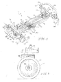
- a hospital stretcher 10 is shown in Fig. 1 as having an upper frame 12 for supporting a mattress 14 having an upwardly facing patient support surface 16.
- stretcher 10 also includes a lower frame 18 coupled to the upper frame 12, lower frame 18 being substantially covered by a shroud 20.
- Stretcher 10 induces head end 24 and a foot end 22.
- head end 24 will be used to denote any referred-to object that is positioned to lie nearest the head end 24 of stretcher 10
- foot end 22 will be used to denote the end of any referred-to object that is positioned to lie nearest the foot end 22 of the stretcher 10.
- upper frame 12 is movably supported above lower frame 18 by a lifting mechanism 26, shown in Fig. 1 .
- Lifting mechanism 26 illustratively includes a head end hydraulic cylinder 30 and a foot end hydraulic cylinder 28, both of which are covered by flexible rubber boots 32,
- Casters 34, 36, 38 and 40 are mounted to lower frame 18, one at each corner, so that stretcher 10 can be rolled over a floor 42 across which a patient is being transported.
- Several foot pedals 44 are pivotally coupled to lower flame 18 and are coupled to the lifting mechanism 26 to control the vertical movement of head end 24 and foot end 22 of the upper frame 12 relative to the lower frame 18.
- Lower frame 18 has four corners. Stretchers of this type are shown in U.S. Patents Nos.
- Fig. 2 shows lower frame 18 exposed without upper frame 12 or shroud 20, so that the moving parts herein described can be better viewed.
- Lower frame 18 illustratively has two longitudinal ends, the head end 24 and the foot end 22.
- the illustrative embodiment includes a fifth wheel 46, which may also be referred to as a steering wheel.
- Fifth wheel 46 is movable between a raised position, shown in Fig. 9 , and a lowered position, shown in Fig. 7 .
- Fifth wheel 46 engages floor 42 when in its lowered position, as can be seen in Fig. 7 .
- the floor-engaging fifth wheel 46 facilitates steering of stretcher 10 when the fifth wheel 46 is in the lowered position, as shown in Fig.
- fifth wheel 46 is desirably moved into the raised position, shown in Fig. 9 , so that casters 34, 36, 38 and 40 can pivot about their axes and allow stretcher 10 to move sideways.
- the illustrative fifth wheel 46 is actuated between the raised position and the lowered position by side actuator pedals 48, 50 and by a brake actuator or brake-actuating bar 52 and wheel-actuating bar 54.
- Brake-actuating bar 52 is coupled to two corners at the longitudinal foot end 22 of stretcher 10
- wheel-actuating bar 54 is coupled to two corners at the longitudinal head end 24 of stretcher 10.
- side actuator pedals 48 cause fifth wheel 46 to engage floor 42 when actuator pedals 48 are moved downwardly by a caregiver, as shown in Figs. 6 and 7 . In the neutral position, wherein the side actuator pedals 48 and 50 are in alignment, as shown in Figs.
- fifth wheel 46 is positioned in the raised position, wherein fifth wheel 46 is not engaging floor 42, as can be seen in Fig. 9 .
- the intermediate position, as fifth wheel 46 is moved between the raised position and the lowered position, or vice versa, can be seen in Fig. 8 .
- side actuator pedals 48 and 50 are linked to each other such that downward movement of one of the actuator pedals 48 causes actuator pedals 50 to move upward, as can be seen in Fig. 6 . Also, downward movement of one side actuator pedal 48 causes the other side actuator pedal 48 to move downward as well.
- Pedals 50 are linked in an identical manner such that pedals 50 move either upward or downward together. Such coordinated linkage between the side actuator pedals 48, 50 is described in more detail herein below.
- Side actuator pedals 48, 50 are also linked to brake-actuating bar 52 and wheel-actuating bar 54. Illustratively, as side actuator pedals 48 are moved downwardly, wheel-actuating bar 54 is caused to move downwardly. Likewise, if wheel-actuating bar 54 is moved downwardly by a care taker, side actuator pedals 48 will move downwardly via a manner described in more detail below.
- brake-actuating bar 52 moves downwardly, and side actuator pedals 48 and wheel-actuating bar 54 move upwardly.
- brake-actuating bar 52 and wheel-actuating bar 54 extend outwardly from lower frame 18 substantially parallel to floor 42.
- brake-actuating bar 52 When brake-actuating bar 52 or side actuator pedals 50 are urged downwardly by a care taker into a position shown in Fig. 4 , a brake or brake mechanism 56 in at least one of the casters 34, 36, 38, 40 is caused to actuate, as can be seen in Fig. 5 .
- brake-actuating bar 52 includes a step portion 63 disposed between two connecting portions 65, as can be seen in Figs. 2 and 4 . Connecting portions 65 connect brake-actuating bar 52 to an outside edge of each corner of lower frame 18.
- Wheel-actuating bar 54 is constructed in a similar fashion,
- brake mechanism 56 comprises a pin configured to move in the direction indicated by arrow 57 toward the rubberized periphery 58 of the caster wheel 60, Caster 36 is illustratively shown in Fig. 5 , however, it should be understood that other casters 34, 38, and 40 can be similarly constructed.
- wheel-actuating bar 54 When wheel-actuating bar 54 is urged downwardly from the position shown in Fig. 4 to the position shown in Figs. 2-3 (the neutral position), side actuator pedals 48 are urged into the neutral position, and brake mechanism 56 is then released from its engagement with the caster wheel periphery 58.
- brake mechanism 56 functions in the following manner.
- Caster wheels 34, 36, 38 40 are commercially available as model number 2446sxp200r36-32, and manufactured by Tente Casters, Inc., 2266 South Park Drive, Heborn, KY 41048.
- Such a caster illustratively includes brake mechanism 56 as part of the unit.
- Such a caster also includes a wheel 60 having a rubberized periphery 58.
- brake mechanism 56 moves downwardly inside caster frame 61 to engage rubberized periphery 58 of wheel 60, thereby causing wheel 60 to be held in place.
- Brake mechanism 56 is operated in the following manner. As brake-actuating bar 52 or side actuator pedals 50 are urged downwardly by a caregiver, brake-actuating bar 52 pivots about shaft 62, causing a hex portion 64 of shaft 62 (visible in Fig. 5 ) to move brake mechanism 56 downwardly in a direction indicated by arrow 57. Shaft 62 is illustratively a hex rod, although other configurations are within the scope of the disclosure. Such actuation of brake mechanism 56 is illustratively synchronized between all four casters 34, 36, 38, 40, although it is contemplated that less than four casters can be engaged by a brake mechanism 56, and still result in stretcher 10 being locked in place.
- Wheel-actuating bar 54 is fixedly connected to shaft 68
- brake-actuating bar 52 is fixedly connected to shaft 62.
- Shaft 62 and shaft 68 are journaled for rotation about their respective axes 90, 92.
- ends of shaft 62 are supported by foot end 22 corners of lower frame 18 and tips 91,93 of shaft 62 extend beyond the perimeter of the corners such that brake-actuating bar 52 attaches adjacent shaft tips 91, 93.
- ends of shaft 68 are supported by head end 24 corners of lower frame 18 and tips 95, 97 of shaft 68 extend beyond the perimeter of the corners such that wheel actuating actuating bar 54 attaches adjacent shaft tips 95, 97.
- Movement of wheel-actuating bar 54 causes shaft 68 to rotate about its axis 92, just as actuation of brake-actuating bar 52 causes shaft 62 to rotate about its axis 90.
- shaft 68 is fixedly coupled to shoulders 70, 72, which are in turn pivotably coupled to ends of arms 74, 76, respectively.
- shaft 62 is fixedly coupled to shoulders 78, 80, which are pivotably coupled to ends of arms 82, 84, respectively.
- Shoulders 70, 72, 78, 80 are illustratively L-shaped and formed of metal, although other constructions are within the scope of the disclosure.
- Shoulders 70, 72, 78 and 80 are pivotably coupled to the respective arms 74, 76, 82, 84 via pins 86, as can be seen in Fig. 4 .
- Arm 74 is also coupled to arm 82, and arm 76 is to arm 84 via pins 85 near the central portion of lower frame 18, as can be seen in the enlarged view shown in Fig. 3 .
- Such a construction provides for shaft 62 to move in conjunction with shaft 68, and likewise brake-actuating bar 52 to move in conjunction with wheel-actuating bar 54 and side actuator pedals 48, 50.
- shaft 62 pivots counterclockwise in the direction shown by arrow 88 about axis 90 (see also Fig. 5 ).
- the rotation about axis 90 causes shoulders 78, 80 to also rotate about axis 90, thereby moving connected arms 82, 84 toward head end 24.
- arms 82, 84 are linked to arms 74, 76, the longitudinal movement from arms 82, 84 results in movement of shoulders 70, 72 at head end 24.
- Shoulders 70, 72 are caused to pivot counterclockwise about axis 92 in the direction indicated by arrow 94, as can be seen in Fig. 4 .
- This movement results in shaft 68 also rotating in direction 94 about axis 92.
- Movement of side actuator pedals 48, 50 is coordinated with movement of brake-actuating bar 52 and wheel-actuating bar 54 in the following manner.
- a T-shaped bell crank 96 connects arms 74, 82 to pedals 48, 50.
- a second T-shaped bell crank 98 connects the arms 76, 84 to pedals 48, 50, as can be seen in Figs. 3 and 7-9 .
- each pedal 48, 50 is connected to bell crank 98 via a link 100.
- Links 100 illustratively use a ball and stud type of interface with bell cranks 96, 98.
- Pedals 48, 50 pivot about pins 102 having a longitudinal axis, which are mounted under side frame member 104 of lower frame 18.
- bell cranks 96, 98 are caused to pivot counterclockwise (as viewed from Fig. 7 ) about shaft 106 by forces delivered through links 100. Pivoting movement causes fifth wheel 46 to move downwardly toward floor 42, such movement being described in more detail herein.
- Bell cranks 96, 98 are fixedly connected to each other via shaft 106 such that pivoting movement of one bell crank 96 or 98 causes the other to pivot about the axis of shaft 106 in the same direction. However, it should be understood that pivoting movement of one bell crank 96, 98 is also transferred to the other bell crank via arms 74, 76, 82, 84, shoulders 70, 72, 78, 80, and shafts 62, 68.
- pedal 48 moves downwardly with the pivoting of bell crank 96 about shaft 106
- pedal 50 moves upwardly to the position shown in Fig. 7 .
- bell crank 98 pivots about the axis of the shaft 106, and the other pedal 50 moves upwardly, as can be seen in Fig. 6 .
- brake-actuating bar 52 is also caused to move upwardly and wheel-actuating bar 54 is caused to move downwardly, as can be seen in Fig. 6 .
- Fifth wheel 46 is moved between its lowered and raised positions in the following manner. Illustratively, as can be seen in Figs. 7-9 , fifth wheel 46 pivots about the axis of shaft 108 (visible in perspective in Fig. 3 ), which is mounted to lower frame 18 of the stretcher 10. In the lowered position, shown in Fig. 7 , upper portion 110 of bell crank 96 has been moved in the counterclockwise direction indicated by arrow 112. Simultaneously with the movement of upper portion 110, radially extending arm 114, which extends from a central portion of shaft 106 in a direction radially opposite that of upper portion 110 of bell crank 96, moves counterclockwise such that its distal end 115 moves toward head end 24 of stretcher 10.
- link 116 Such movement causes link 116 to also move toward head end 24, and thereby cause pivot arm 118 to pivot about pin 120.
- link 116 is rigid and pivots relative to arm 114 at one end, and pivots relative to pivot arm 118 at the other end.
- Pivot arm 118 is pivotably coupled to link 116 at one end, and pivotably coupled to wheel arm 122 at the other end.
- pivot arm 118 is angled and pivots about pin 120 at the angle.
- Swing arm 124 supports pin 120 and pivot arm 118 pivots about the axis defined by pin 120. Swing arm 124 pivots between a substantially vertical position, shown in Fig. 7 , and an angled position, shown in Fig. 9 .
- the combination of link 116, swing arm 124, and pivot arm 118 causes the substantially longitudinal movement of distal end 115 of arm 114 to be converted to substantially downward movement by pivot arm 118, thereby causing wheel arm 122 to pivot about shaft 108 and move fifth wheel 46 into engagement with floor 42.
- a caregiver In order to disengage fifth wheel 46 from floor 42, a caregiver must depress either one of side actuator pedals 50 or brake-actuating bar 52. As either a side actuator pedal 50 or the brake-actuating bar 52 is urged downwardly, radially extending arm 114 pivots clockwise (as viewed from Fig. 7 ) with shaft 106, thereby moving link 116 in a substantially longitudinal direction toward foot end 22. Link 116 causes pivot arm 118 to pivot about pin 120, and thereby urge wheel arm 122 away from floor 42 to the intermediate position shown in Fig. 8 . In the intermediate position, fifth wheel 46 is illustratively spaced approximately 1/2 inch (1.27 cm) from floor 42.
- radially extending arm 114 continues to pivot clockwise about shaft 106 to a position shown in Fig. 9 .
- brake mechanism 56 engages the rubberized periphery 58 of a wheel 60, as described above, and fifth wheel 46 is retained in its raised position.
- fifth wheel 46 is illustratively spaced approximately two inches (5.08 cm) from floor 42.
- pedals 48, 50 on the sides of stretches 10 permits a caregiver to operate both the brake mechanisrn(s) 56 and the fifth wheel 46 of the stretcher 10 while being located on the side of the patient. Also, by positioning wheel-actuating bar 54 at the head end 24 of the stretcher 10, a caregiver pushing stretcher 10 from the head end (which is common in medical practices because the caregiver is then adjacent the patient's head) can easily engage the fifth wheel 46, and thereby more easily steer the stretcher 10 while pushing the patient.
- a caregiver When the patient has reached the destination, a caregiver will typically position the patient such that the head end 24 of the stretcher is aligned with a wall of the hospital room, and then apply the brake mechanism 56 to maintain the stretcher 10 in that position.
- the application of the brake mechanism 56 is facilitated by positioning brake-actuating bar 52 at the foot end 22 of the stretcher 10.
- lever assembly 130 having a foot pad 132, 134 at each end can be used to operate brake mechanism 56 and fifth wheel 46, as disclosed above.
- Lever assembly 130 is also illustratively connected to shaft 62 via gears 136, 138.
- Gears 136, 138 are illustratively configured to reduce the necessary movement of lever assembly 130 by a half (i.e., a 2:1 gear ratio).
- Lever assemblies 130 are illustratively positioned at each corner of lower frame 18, however, other configurations are within the scope of the disclosure. For example, lever assemblies 130 could be placed at opposite corners.
Applications Claiming Priority (2)
| Application Number | Priority Date | Filing Date | Title |
|---|---|---|---|
| US10/349,428 US7302717B2 (en) | 2003-01-22 | 2003-01-22 | Side and end brake/steer mechanism for stretchers |
| EP04704083A EP1589921B1 (fr) | 2003-01-22 | 2004-01-21 | Mecanisme de freinage/pilotage lateral et d'extremite pour civieres |
Related Parent Applications (1)
| Application Number | Title | Priority Date | Filing Date |
|---|---|---|---|
| EP04704083.7 Division | 2004-01-21 |
Publications (3)
| Publication Number | Publication Date |
|---|---|
| EP2283799A2 true EP2283799A2 (fr) | 2011-02-16 |
| EP2283799A3 EP2283799A3 (fr) | 2012-02-29 |
| EP2283799B1 EP2283799B1 (fr) | 2013-05-01 |
Family
ID=32712730
Family Applications (2)
| Application Number | Title | Priority Date | Filing Date |
|---|---|---|---|
| EP04704083A Expired - Lifetime EP1589921B1 (fr) | 2003-01-22 | 2004-01-21 | Mecanisme de freinage/pilotage lateral et d'extremite pour civieres |
| EP10191861.3A Expired - Lifetime EP2283799B1 (fr) | 2003-01-22 | 2004-01-21 | Mécanisme latéral et d'extrémité de frein/direction pour brancard |
Family Applications Before (1)
| Application Number | Title | Priority Date | Filing Date |
|---|---|---|---|
| EP04704083A Expired - Lifetime EP1589921B1 (fr) | 2003-01-22 | 2004-01-21 | Mecanisme de freinage/pilotage lateral et d'extremite pour civieres |
Country Status (6)
| Country | Link |
|---|---|
| US (3) | US7302717B2 (fr) |
| EP (2) | EP1589921B1 (fr) |
| AT (1) | ATE493958T1 (fr) |
| CA (1) | CA2507229A1 (fr) |
| DE (1) | DE602004030886D1 (fr) |
| WO (1) | WO2004064699A1 (fr) |
Cited By (1)
| Publication number | Priority date | Publication date | Assignee | Title |
|---|---|---|---|---|
| WO2024074956A1 (fr) * | 2022-10-07 | 2024-04-11 | Loadhog Limited | Système de frein à engrenages pour équipement de manipulation manuelle |
Families Citing this family (69)
| Publication number | Priority date | Publication date | Assignee | Title |
|---|---|---|---|---|
| AU2003274957B2 (en) * | 2002-09-06 | 2009-07-16 | Hill-Rom Services, Inc. | Hospital bed |
| US7028356B2 (en) * | 2002-11-26 | 2006-04-18 | Ge Medical Systems Global Technology Company, Llc | Multiconfiguration braking system |
| US6986179B2 (en) * | 2002-11-26 | 2006-01-17 | Ge Medical Systems Global Technology Company, Llc | Grouted tilting patient positioning table for vascular applications |
| US7302717B2 (en) * | 2003-01-22 | 2007-12-04 | Hill-Rom Services, Inc. | Side and end brake/steer mechanism for stretchers |
| US7125167B2 (en) | 2003-03-04 | 2006-10-24 | Ge Medical Systems Global Technology Company, Llc | Method and apparatus for tilting in a patient positioning system |
| EP1624841B1 (fr) | 2003-05-21 | 2010-01-27 | Hill-Rom Services, Inc. | Lit d'hopital |
| US7690059B2 (en) * | 2005-12-19 | 2010-04-06 | Stryker Corporation | Hospital bed |
| US9038217B2 (en) | 2005-12-19 | 2015-05-26 | Stryker Corporation | Patient support with improved control |
| US7712166B2 (en) * | 2004-12-03 | 2010-05-11 | Stryker Corporation | Bed siderail and support structure |
| US20070080030A1 (en) * | 2005-10-06 | 2007-04-12 | Sunrise Medical Hhg Inc. | Brake assembly for beds |
| US9107788B2 (en) * | 2005-10-07 | 2015-08-18 | MediGlider Corp. | Cam mechanism to raise steering wheel of patient transfer device |
| US8452508B2 (en) * | 2005-11-10 | 2013-05-28 | Linet Spol. S.R.O. | Braking system for patient support |
| US7657953B2 (en) * | 2005-11-17 | 2010-02-09 | Hill-Rom Services, Inc. | Birthing bed calf support |
| US11246776B2 (en) | 2005-12-19 | 2022-02-15 | Stryker Corporation | Patient support with improved control |
| US8006332B2 (en) | 2005-12-19 | 2011-08-30 | Stryker Corporation | Hospital bed |
| US7810822B2 (en) * | 2006-01-19 | 2010-10-12 | Hill-Rom Services, Inc. | Stretcher having hand actuated caster braking apparatus |
| US7922183B2 (en) | 2006-01-19 | 2011-04-12 | Hill-Rom Services, Inc. | Stretcher having hand actuated wheel braking apparatus |
| CZ17216U1 (cs) * | 2006-11-09 | 2007-02-05 | Linet, Spol. S R. O. | Sestava vodicího kolecka, zejména pro nemocnicní luzko |
| CA2700907C (fr) | 2007-10-02 | 2014-12-09 | Livengood Engineering, Inc. | Systeme de support de patient modulaire |
| US8104118B2 (en) | 2008-01-21 | 2012-01-31 | Stryker Corporation | Hospital bed |
| DE102008021604B4 (de) * | 2008-04-30 | 2016-06-30 | Fresenius Medical Care Deutschland Gmbh | Einrichtung zum Betätigen von Bremseinrichtungen einer fahrbaren Vorrichtung, fahrbares Gestell und medizinisches Gerät |
| FR2930922B1 (fr) * | 2008-05-06 | 2010-06-11 | Medicatlantic Sa | Systeme de freinage pour lit sur roulettes |
| US20100077548A1 (en) * | 2008-09-19 | 2010-04-01 | Joerns Healthcare, Inc. | Visual indicator assembly for brake for bed |
| GB201003218D0 (en) * | 2010-02-25 | 2010-04-14 | Snell Thomas B | Improvements relating to platform devices |
| CN102442334B (zh) * | 2010-10-09 | 2016-04-20 | 深圳迈瑞生物医疗电子股份有限公司 | 一种中央控制刹车系统及推车型可移动式医疗设备 |
| DE102010051126A1 (de) * | 2010-11-11 | 2012-05-16 | Berchtold Holding Gmbh | Operationstisch |
| US8522379B2 (en) | 2010-11-15 | 2013-09-03 | Hill-Rom Services, Inc. | Hospital bed foot section with caster cutouts |
| US8341779B2 (en) | 2010-12-06 | 2013-01-01 | Hill-Rom Services, Inc. | Retractable foot caster supports |
| US8516630B2 (en) * | 2010-12-08 | 2013-08-27 | University Of Massachusetts | Convertible wheelchair |
| US9173795B2 (en) * | 2011-02-08 | 2015-11-03 | Hill-Rom Services, Inc. | Brake pedal mechanism for hospital bed |
| US20130000040A1 (en) * | 2011-06-29 | 2013-01-03 | Edward Conley | Reclining Mobility Chair And Method Of Use |
| US8418315B1 (en) * | 2012-01-11 | 2013-04-16 | Sunny Castors Co., Ltd. | Combination castor brake system whose castor assemblies are braked and positioned simultaneously |
| US8516656B2 (en) * | 2012-01-11 | 2013-08-27 | Sunny Castors Co., Ltd. | Combination castor whose castor units are braked simultaneously |
| CN103211686B (zh) * | 2012-01-20 | 2015-08-26 | 刘宁 | 医用神经科病人治疗护理床 |
| US10004651B2 (en) * | 2012-09-18 | 2018-06-26 | Stryker Corporation | Patient support apparatus |
| US9579241B2 (en) | 2012-10-12 | 2017-02-28 | Steelcase Inc. | Support arrangement with activation mechanism |
| US9114849B2 (en) * | 2013-04-29 | 2015-08-25 | Gulshan Prem Choppla | Student, teacher, administrative and research coordinating helper |
| US10322045B1 (en) | 2013-05-29 | 2019-06-18 | Paul Cuneo | Footboard for hospital bed with therapeutic mechanisms housed within |
| CN104228460B (zh) * | 2013-06-14 | 2019-02-19 | 北京谊安医疗系统股份有限公司 | 脚轮装置 |
| GB2516051B (en) * | 2013-07-09 | 2016-06-08 | Eschmann Holdings Ltd | Surgical tables |
| US9603764B2 (en) | 2014-02-11 | 2017-03-28 | Medline Industries, Inc. | Method and apparatus for a locking caster |
| US9918888B2 (en) * | 2014-03-21 | 2018-03-20 | Medline Industries, Inc. | Locking mechanism with pivotable foot actuation lever |
| CN104589915A (zh) * | 2014-03-26 | 2015-05-06 | 宁波秀禾五金机械有限公司 | 一种全塑脚轮 |
| US9132053B1 (en) * | 2014-06-06 | 2015-09-15 | UMF Medical | Retractable wheel base |
| CN105221606A (zh) * | 2014-07-02 | 2016-01-06 | 南京普爱射线影像设备有限公司 | 一种医用移动式x射线机刹车和解锁装置 |
| US9994072B2 (en) * | 2014-09-17 | 2018-06-12 | Medical Depot, Inc. | Patient care bed |
| EP3247611B1 (fr) * | 2015-01-21 | 2020-12-09 | Dane Technologies Inc. | Pousseurs de chariots, chariots encastrables, systèmes, procédés et dispositifs associés |
| USD787073S1 (en) | 2015-03-12 | 2017-05-16 | Lgms, Llc | Patient support cart with mounting plate |
| USD783389S1 (en) | 2015-03-12 | 2017-04-11 | Lgms, Llc | Mounting plate for a patient support cart |
| US10507151B2 (en) | 2015-07-23 | 2019-12-17 | Stryker Corporation | Patient support apparatus with side rail |
| US10912685B2 (en) | 2015-07-24 | 2021-02-09 | Stryker Corporation | System and method of braking for a patient support apparatus |
| WO2017028035A1 (fr) * | 2015-08-14 | 2017-02-23 | 深圳迈瑞生物医疗电子股份有限公司 | Système de frein à commande centrale et dispositif médical mobile |
| US10568792B2 (en) | 2015-10-28 | 2020-02-25 | Stryker Corporation | Systems and methods for facilitating movement of a patient transport apparatus |
| US10377403B2 (en) | 2015-11-06 | 2019-08-13 | Caster Concepts, Inc. | Powered utility cart and compliant drive wheel therefor |
| PL3423020T3 (pl) * | 2016-03-01 | 2023-07-17 | Arjo IP Holding Aktiebolag | Ręczny układ podnoszący wspomagane elektrycznie koło łóżka |
| CN108785000B (zh) * | 2017-04-28 | 2022-05-03 | 通用电气公司 | 可移动患者床 |
| MX2019013602A (es) * | 2017-05-15 | 2020-08-20 | Huntleigh Technology Ltd | Muelle de levantamiento reversible para elevar y descender una quinta rueda de cama medica. |
| US10806653B2 (en) | 2017-12-21 | 2020-10-20 | Stryker Corporation | Patient transport apparatus with electro-mechanical braking system |
| US11071662B2 (en) | 2017-12-28 | 2021-07-27 | Stryker Corporation | Patient transport apparatus with controlled auxiliary wheel speed |
| US10799403B2 (en) | 2017-12-28 | 2020-10-13 | Stryker Corporation | Patient transport apparatus with controlled auxiliary wheel deployment |
| US11628102B2 (en) * | 2018-05-21 | 2023-04-18 | Hill-Rom Services, Inc. | Patient support apparatus adaptable to multiple modes of transport |
| US11304860B2 (en) | 2018-11-21 | 2022-04-19 | Stryker Corporation | Patient transport apparatus with auxiliary wheel system |
| US11484447B2 (en) | 2018-11-21 | 2022-11-01 | Stryker Corporation | Patient transport apparatus with controlled auxiliary wheel deployment |
| CN109907890B (zh) * | 2019-02-28 | 2020-07-21 | 丽水市中心医院 | 一种隔离患者转运车 |
| US11718128B2 (en) * | 2019-12-04 | 2023-08-08 | GE Precision Healthcare LLC | Ergonomic central wheel lock for ultrasound consoles |
| EP4084762A4 (fr) * | 2019-12-30 | 2024-02-28 | Stryker Corp | Appareil de transport de patient avec système de freinage électromécanique |
| US11806296B2 (en) | 2019-12-30 | 2023-11-07 | Stryker Corporation | Patient transport apparatus with controlled auxiliary wheel speed |
| US11641950B2 (en) * | 2020-06-05 | 2023-05-09 | Industrial Woodworking Corporation | Height adjustable bassinet |
| WO2024062404A1 (fr) * | 2022-09-21 | 2024-03-28 | Howard Wright Limited | Système de rétraction motorisé destiné à une roue |
Citations (8)
| Publication number | Priority date | Publication date | Assignee | Title |
|---|---|---|---|---|
| US5348326A (en) | 1993-03-02 | 1994-09-20 | Hill-Rom Company, Inc. | Carrier with deployable center wheels |
| US5806111A (en) | 1996-04-12 | 1998-09-15 | Hill-Rom, Inc. | Stretcher controls |
| US5996149A (en) | 1997-07-17 | 1999-12-07 | Hill-Rom, Inc. | Trauma stretcher apparatus |
| US6000076A (en) | 1996-10-23 | 1999-12-14 | Hill-Rom, Inc. | Procedural stretcher recline controls |
| US6076208A (en) | 1997-07-14 | 2000-06-20 | Hill-Rom, Inc. | Surgical stretcher |
| US6282738B1 (en) | 1998-08-07 | 2001-09-04 | Hill-Rom, Inc. | Ob/Gyn stretcher |
| US6330926B1 (en) | 1999-09-15 | 2001-12-18 | Hill-Rom Services, Inc. | Stretcher having a motorized wheel |
| US6446283B1 (en) | 1999-01-22 | 2002-09-10 | Hill-Rom Services, Inc. | Convertible stretcher |
Family Cites Families (30)
| Publication number | Priority date | Publication date | Assignee | Title |
|---|---|---|---|---|
| US2098229A (en) | 1935-08-14 | 1937-11-09 | Richard C Coupland | Discharger for projectiles |
| US2096229A (en) | 1936-08-03 | 1937-10-19 | John A Dudley | Caster brake |
| US2572548A (en) | 1949-05-16 | 1951-10-23 | Daniel I Weisz | Brake structure for platform type casters or the like |
| US3304116A (en) | 1965-03-16 | 1967-02-14 | Stryker Corp | Mechanical device |
| US3493085A (en) | 1968-03-18 | 1970-02-03 | Colson Corp The | Positive locking caster brake |
| US3635491A (en) | 1970-04-17 | 1972-01-18 | Whirlpool Co | Caster jack mechanism for portable appliances |
| US4175783A (en) | 1978-02-06 | 1979-11-27 | Pioth Michael J | Stretcher |
| US4276962A (en) | 1979-03-09 | 1981-07-07 | American Hospital Supply Corporation | Caster brake for stretcher or the like |
| US4309791A (en) | 1979-03-09 | 1982-01-12 | American Hospital Supply Corporation | Caster brake and swivel lock for stretcher or the like |
| US4439879A (en) | 1980-12-01 | 1984-04-03 | B-W Health Products, Inc. | Adjustable bed with improved castor control assembly |
| JPH04500463A (ja) | 1988-03-23 | 1992-01-30 | ファーランド ロバート | 患者支持装置 |
| US4922574A (en) | 1989-04-24 | 1990-05-08 | Snap-On Tools Corporation | Caster locking mechanism and carriage |
| US5377372A (en) | 1993-03-31 | 1995-01-03 | Hill-Rom Company, Inc. | Hospital bed castor control mechanism |
| US5450639A (en) | 1993-12-21 | 1995-09-19 | Hill-Rom Company, Inc. | Electrically activated visual indicator for visually indicating the mode of a hospital bed castor |
| US5497856A (en) | 1994-08-31 | 1996-03-12 | Colson Caster Corporation | Locking caster brake assembly |
| US5878452A (en) | 1996-12-03 | 1999-03-09 | Hill-Rom, Inc. | Long term care bed controls |
| US6089593A (en) | 1997-02-10 | 2000-07-18 | Hill-Rom, Inc. | Ambulatory care chair |
| US6611979B2 (en) | 1997-09-23 | 2003-09-02 | Hill-Rom Services, Inc. | Mattress having a retractable foot section |
| US6240579B1 (en) | 1998-01-07 | 2001-06-05 | Stryker Corporation | Unitary pedal control of brake and fifth wheel deployment via side and end articulation with additional unitary pedal control of height of patient support |
| US6321878B1 (en) | 1999-03-05 | 2001-11-27 | Hill-Rom Services, Inc. | Caster and braking system |
| US6598247B1 (en) * | 1999-10-27 | 2003-07-29 | Hill-Rom Services, Inc. | Stretcher with mechanical power assist |
| US6421854B1 (en) * | 2000-02-18 | 2002-07-23 | Hill-Rom Services, Inc. | Imaging stretcher |
| US6460205B1 (en) | 2000-06-12 | 2002-10-08 | Stryker Corporation | Caster brake mechanism |
| US6453508B1 (en) | 2001-02-21 | 2002-09-24 | Standex International Corp. | Wedging brake for a caster |
| DE10113805B4 (de) | 2001-03-21 | 2006-02-23 | Herbert Brustmann | Fahrgestell für einen Behandlungstisch insbesondere für chirurgische Eingriffe |
| US6865775B2 (en) | 2001-09-05 | 2005-03-15 | Hill-Rom Services, Inc. | Hospital bed caster apparatus |
| DE10147142B4 (de) | 2001-09-25 | 2005-03-24 | Völker Möbelproduktionsgesellschaft mbH | Bett, insbesondere Kranken- oder Pflegebett |
| US6820294B2 (en) | 2002-02-26 | 2004-11-23 | Stryker Corporation | Linkage for lift/lowering control for a patient supporting platform |
| FR2836375B1 (fr) | 2002-02-28 | 2004-12-17 | Hill Rom Sas | Cadre de dispositif a usage medical ou paramedical de support roulant d'une personne, a roulettes facilement demontables, et dispositif ainsi equipe |
| US7302717B2 (en) | 2003-01-22 | 2007-12-04 | Hill-Rom Services, Inc. | Side and end brake/steer mechanism for stretchers |
-
2003
- 2003-01-22 US US10/349,428 patent/US7302717B2/en not_active Expired - Lifetime
-
2004
- 2004-01-21 CA CA002507229A patent/CA2507229A1/fr not_active Abandoned
- 2004-01-21 WO PCT/US2004/001521 patent/WO2004064699A1/fr active Application Filing
- 2004-01-21 EP EP04704083A patent/EP1589921B1/fr not_active Expired - Lifetime
- 2004-01-21 AT AT04704083T patent/ATE493958T1/de not_active IP Right Cessation
- 2004-01-21 EP EP10191861.3A patent/EP2283799B1/fr not_active Expired - Lifetime
- 2004-01-21 DE DE602004030886T patent/DE602004030886D1/de not_active Expired - Lifetime
-
2006
- 2006-01-30 US US11/342,449 patent/US7346942B2/en not_active Expired - Lifetime
-
2007
- 2007-08-13 US US11/837,726 patent/US7480948B2/en not_active Expired - Lifetime
Patent Citations (9)
| Publication number | Priority date | Publication date | Assignee | Title |
|---|---|---|---|---|
| US5348326A (en) | 1993-03-02 | 1994-09-20 | Hill-Rom Company, Inc. | Carrier with deployable center wheels |
| US5806111A (en) | 1996-04-12 | 1998-09-15 | Hill-Rom, Inc. | Stretcher controls |
| US5987671A (en) | 1996-04-12 | 1999-11-23 | Hill-Rom, Inc. | Stretcher center wheel mechanism |
| US6000076A (en) | 1996-10-23 | 1999-12-14 | Hill-Rom, Inc. | Procedural stretcher recline controls |
| US6076208A (en) | 1997-07-14 | 2000-06-20 | Hill-Rom, Inc. | Surgical stretcher |
| US5996149A (en) | 1997-07-17 | 1999-12-07 | Hill-Rom, Inc. | Trauma stretcher apparatus |
| US6282738B1 (en) | 1998-08-07 | 2001-09-04 | Hill-Rom, Inc. | Ob/Gyn stretcher |
| US6446283B1 (en) | 1999-01-22 | 2002-09-10 | Hill-Rom Services, Inc. | Convertible stretcher |
| US6330926B1 (en) | 1999-09-15 | 2001-12-18 | Hill-Rom Services, Inc. | Stretcher having a motorized wheel |
Cited By (1)
| Publication number | Priority date | Publication date | Assignee | Title |
|---|---|---|---|---|
| WO2024074956A1 (fr) * | 2022-10-07 | 2024-04-11 | Loadhog Limited | Système de frein à engrenages pour équipement de manipulation manuelle |
Also Published As
| Publication number | Publication date |
|---|---|
| ATE493958T1 (de) | 2011-01-15 |
| CA2507229A1 (fr) | 2004-08-05 |
| US20060137092A1 (en) | 2006-06-29 |
| WO2004064699A1 (fr) | 2004-08-05 |
| US7480948B2 (en) | 2009-01-27 |
| US7346942B2 (en) | 2008-03-25 |
| DE602004030886D1 (de) | 2011-02-17 |
| US20070271700A1 (en) | 2007-11-29 |
| EP1589921A1 (fr) | 2005-11-02 |
| EP2283799B1 (fr) | 2013-05-01 |
| US20040139545A1 (en) | 2004-07-22 |
| EP1589921B1 (fr) | 2011-01-05 |
| US7302717B2 (en) | 2007-12-04 |
| EP2283799A3 (fr) | 2012-02-29 |
Similar Documents
| Publication | Publication Date | Title |
|---|---|---|
| US7480948B2 (en) | Patient support apparatus having a brake/steer mechanism with a foot pedal gear reducer | |
| US6421854B1 (en) | Imaging stretcher | |
| US9173795B2 (en) | Brake pedal mechanism for hospital bed | |
| WO2011155177A1 (fr) | Lit, procédé de formation d'un lit par union, procédé de séparation d'un lit | |
| EP1810652B1 (fr) | Civière disposant d'un frein de roulettes commandé manuellement | |
| US7021407B2 (en) | Motorized propulsion system for a bed | |
| EP2305201B1 (fr) | Support pour mollets pour un lit d'accouchement | |
| EP1974706B1 (fr) | Civière disposant d'un frein de roulettes actionné manuellement | |
| JP2001511047A (ja) | 移動介護椅子 | |
| US7062805B2 (en) | Pedal control of brake and auxiliary wheel deployment via side and end articulation | |
| EP2484331A2 (fr) | Mécanisme de déploiement de roue motorisée centrale pour support de patient | |
| JP4881125B2 (ja) | ストレッチャー | |
| EP1185201B1 (fr) | Dispositif de levage de plateau a rayons x de civiere utilisee en traumatologie | |
| US20230091283A1 (en) | Bed lifting mechanism | |
| US20220378634A1 (en) | Bed lifting mechanism | |
| GB2615603A (en) | Brake mechanism | |
| JP2022072890A (ja) | 車椅子 | |
| JPH0467813A (ja) | 寝台の床起伏機構 | |
| JPH0415054A (ja) | 移動仰臥台に於けるキヤスターの連動操作機構 |
Legal Events
| Date | Code | Title | Description |
|---|---|---|---|
| PUAI | Public reference made under article 153(3) epc to a published international application that has entered the european phase |
Free format text: ORIGINAL CODE: 0009012 |
|
| 17P | Request for examination filed |
Effective date: 20101215 |
|
| AC | Divisional application: reference to earlier application |
Ref document number: 1589921 Country of ref document: EP Kind code of ref document: P |
|
| AK | Designated contracting states |
Kind code of ref document: A2 Designated state(s): AT BE BG CH CY CZ DE DK EE ES FI FR GB GR HU IE IT LI LU MC NL PT RO SE SI SK TR |
|
| PUAL | Search report despatched |
Free format text: ORIGINAL CODE: 0009013 |
|
| AK | Designated contracting states |
Kind code of ref document: A3 Designated state(s): AT BE BG CH CY CZ DE DK EE ES FI FR GB GR HU IE IT LI LU MC NL PT RO SE SI SK TR |
|
| RIC1 | Information provided on ipc code assigned before grant |
Ipc: A61G 1/02 20060101AFI20120126BHEP Ipc: B60B 33/00 20060101ALI20120126BHEP |
|
| GRAP | Despatch of communication of intention to grant a patent |
Free format text: ORIGINAL CODE: EPIDOSNIGR1 |
|
| GRAS | Grant fee paid |
Free format text: ORIGINAL CODE: EPIDOSNIGR3 |
|
| GRAA | (expected) grant |
Free format text: ORIGINAL CODE: 0009210 |
|
| AC | Divisional application: reference to earlier application |
Ref document number: 1589921 Country of ref document: EP Kind code of ref document: P |
|
| AK | Designated contracting states |
Kind code of ref document: B1 Designated state(s): AT BE BG CH CY CZ DE DK EE ES FI FR GB GR HU IE IT LI LU MC NL PT RO SE SI SK TR |
|
| REG | Reference to a national code |
Ref country code: GB Ref legal event code: FG4D |
|
| REG | Reference to a national code |
Ref country code: AT Ref legal event code: REF Ref document number: 609433 Country of ref document: AT Kind code of ref document: T Effective date: 20130515 Ref country code: CH Ref legal event code: EP |
|
| REG | Reference to a national code |
Ref country code: IE Ref legal event code: FG4D |
|
| REG | Reference to a national code |
Ref country code: DE Ref legal event code: R096 Ref document number: 602004042022 Country of ref document: DE Effective date: 20130704 |
|
| REG | Reference to a national code |
Ref country code: AT Ref legal event code: MK05 Ref document number: 609433 Country of ref document: AT Kind code of ref document: T Effective date: 20130501 |
|
| REG | Reference to a national code |
Ref country code: NL Ref legal event code: VDEP Effective date: 20130501 |
|
| PG25 | Lapsed in a contracting state [announced via postgrant information from national office to epo] |
Ref country code: SI Free format text: LAPSE BECAUSE OF FAILURE TO SUBMIT A TRANSLATION OF THE DESCRIPTION OR TO PAY THE FEE WITHIN THE PRESCRIBED TIME-LIMIT Effective date: 20130501 Ref country code: FI Free format text: LAPSE BECAUSE OF FAILURE TO SUBMIT A TRANSLATION OF THE DESCRIPTION OR TO PAY THE FEE WITHIN THE PRESCRIBED TIME-LIMIT Effective date: 20130501 Ref country code: AT Free format text: LAPSE BECAUSE OF FAILURE TO SUBMIT A TRANSLATION OF THE DESCRIPTION OR TO PAY THE FEE WITHIN THE PRESCRIBED TIME-LIMIT Effective date: 20130501 Ref country code: ES Free format text: LAPSE BECAUSE OF FAILURE TO SUBMIT A TRANSLATION OF THE DESCRIPTION OR TO PAY THE FEE WITHIN THE PRESCRIBED TIME-LIMIT Effective date: 20130812 Ref country code: GR Free format text: LAPSE BECAUSE OF FAILURE TO SUBMIT A TRANSLATION OF THE DESCRIPTION OR TO PAY THE FEE WITHIN THE PRESCRIBED TIME-LIMIT Effective date: 20130802 Ref country code: PT Free format text: LAPSE BECAUSE OF FAILURE TO SUBMIT A TRANSLATION OF THE DESCRIPTION OR TO PAY THE FEE WITHIN THE PRESCRIBED TIME-LIMIT Effective date: 20130902 Ref country code: SE Free format text: LAPSE BECAUSE OF FAILURE TO SUBMIT A TRANSLATION OF THE DESCRIPTION OR TO PAY THE FEE WITHIN THE PRESCRIBED TIME-LIMIT Effective date: 20130501 |
|
| PG25 | Lapsed in a contracting state [announced via postgrant information from national office to epo] |
Ref country code: BG Free format text: LAPSE BECAUSE OF FAILURE TO SUBMIT A TRANSLATION OF THE DESCRIPTION OR TO PAY THE FEE WITHIN THE PRESCRIBED TIME-LIMIT Effective date: 20130801 Ref country code: CY Free format text: LAPSE BECAUSE OF FAILURE TO SUBMIT A TRANSLATION OF THE DESCRIPTION OR TO PAY THE FEE WITHIN THE PRESCRIBED TIME-LIMIT Effective date: 20130501 |
|
| PG25 | Lapsed in a contracting state [announced via postgrant information from national office to epo] |
Ref country code: DK Free format text: LAPSE BECAUSE OF FAILURE TO SUBMIT A TRANSLATION OF THE DESCRIPTION OR TO PAY THE FEE WITHIN THE PRESCRIBED TIME-LIMIT Effective date: 20130501 Ref country code: SK Free format text: LAPSE BECAUSE OF FAILURE TO SUBMIT A TRANSLATION OF THE DESCRIPTION OR TO PAY THE FEE WITHIN THE PRESCRIBED TIME-LIMIT Effective date: 20130501 Ref country code: EE Free format text: LAPSE BECAUSE OF FAILURE TO SUBMIT A TRANSLATION OF THE DESCRIPTION OR TO PAY THE FEE WITHIN THE PRESCRIBED TIME-LIMIT Effective date: 20130501 Ref country code: BE Free format text: LAPSE BECAUSE OF FAILURE TO SUBMIT A TRANSLATION OF THE DESCRIPTION OR TO PAY THE FEE WITHIN THE PRESCRIBED TIME-LIMIT Effective date: 20130501 Ref country code: CZ Free format text: LAPSE BECAUSE OF FAILURE TO SUBMIT A TRANSLATION OF THE DESCRIPTION OR TO PAY THE FEE WITHIN THE PRESCRIBED TIME-LIMIT Effective date: 20130501 |
|
| PG25 | Lapsed in a contracting state [announced via postgrant information from national office to epo] |
Ref country code: NL Free format text: LAPSE BECAUSE OF FAILURE TO SUBMIT A TRANSLATION OF THE DESCRIPTION OR TO PAY THE FEE WITHIN THE PRESCRIBED TIME-LIMIT Effective date: 20130501 Ref country code: IT Free format text: LAPSE BECAUSE OF FAILURE TO SUBMIT A TRANSLATION OF THE DESCRIPTION OR TO PAY THE FEE WITHIN THE PRESCRIBED TIME-LIMIT Effective date: 20130501 Ref country code: RO Free format text: LAPSE BECAUSE OF FAILURE TO SUBMIT A TRANSLATION OF THE DESCRIPTION OR TO PAY THE FEE WITHIN THE PRESCRIBED TIME-LIMIT Effective date: 20130501 |
|
| PLBE | No opposition filed within time limit |
Free format text: ORIGINAL CODE: 0009261 |
|
| STAA | Information on the status of an ep patent application or granted ep patent |
Free format text: STATUS: NO OPPOSITION FILED WITHIN TIME LIMIT |
|
| 26N | No opposition filed |
Effective date: 20140204 |
|
| REG | Reference to a national code |
Ref country code: DE Ref legal event code: R097 Ref document number: 602004042022 Country of ref document: DE Effective date: 20140204 |
|
| PG25 | Lapsed in a contracting state [announced via postgrant information from national office to epo] |
Ref country code: LU Free format text: LAPSE BECAUSE OF FAILURE TO SUBMIT A TRANSLATION OF THE DESCRIPTION OR TO PAY THE FEE WITHIN THE PRESCRIBED TIME-LIMIT Effective date: 20140121 Ref country code: MC Free format text: LAPSE BECAUSE OF FAILURE TO SUBMIT A TRANSLATION OF THE DESCRIPTION OR TO PAY THE FEE WITHIN THE PRESCRIBED TIME-LIMIT Effective date: 20130501 |
|
| REG | Reference to a national code |
Ref country code: CH Ref legal event code: PL |
|
| PG25 | Lapsed in a contracting state [announced via postgrant information from national office to epo] |
Ref country code: CH Free format text: LAPSE BECAUSE OF NON-PAYMENT OF DUE FEES Effective date: 20140131 Ref country code: LI Free format text: LAPSE BECAUSE OF NON-PAYMENT OF DUE FEES Effective date: 20140131 |
|
| REG | Reference to a national code |
Ref country code: IE Ref legal event code: MM4A |
|
| PG25 | Lapsed in a contracting state [announced via postgrant information from national office to epo] |
Ref country code: IE Free format text: LAPSE BECAUSE OF NON-PAYMENT OF DUE FEES Effective date: 20140121 |
|
| REG | Reference to a national code |
Ref country code: FR Ref legal event code: PLFP Year of fee payment: 13 |
|
| PG25 | Lapsed in a contracting state [announced via postgrant information from national office to epo] |
Ref country code: HU Free format text: LAPSE BECAUSE OF FAILURE TO SUBMIT A TRANSLATION OF THE DESCRIPTION OR TO PAY THE FEE WITHIN THE PRESCRIBED TIME-LIMIT; INVALID AB INITIO Effective date: 20040121 Ref country code: TR Free format text: LAPSE BECAUSE OF FAILURE TO SUBMIT A TRANSLATION OF THE DESCRIPTION OR TO PAY THE FEE WITHIN THE PRESCRIBED TIME-LIMIT Effective date: 20130501 |
|
| REG | Reference to a national code |
Ref country code: FR Ref legal event code: PLFP Year of fee payment: 14 |
|
| REG | Reference to a national code |
Ref country code: FR Ref legal event code: PLFP Year of fee payment: 15 |
|
| REG | Reference to a national code |
Ref country code: DE Ref legal event code: R082 Ref document number: 602004042022 Country of ref document: DE Representative=s name: PRUEFER & PARTNER MBB PATENTANWAELTE RECHTSANW, DE |
|
| PGFP | Annual fee paid to national office [announced via postgrant information from national office to epo] |
Ref country code: GB Payment date: 20221221 Year of fee payment: 20 Ref country code: FR Payment date: 20221220 Year of fee payment: 20 |
|
| PGFP | Annual fee paid to national office [announced via postgrant information from national office to epo] |
Ref country code: DE Payment date: 20221220 Year of fee payment: 20 |
|
| REG | Reference to a national code |
Ref country code: DE Ref legal event code: R071 Ref document number: 602004042022 Country of ref document: DE |
|
| REG | Reference to a national code |
Ref country code: GB Ref legal event code: PE20 Expiry date: 20240120 |