EP2283214B1 - Vorrichtung zur förderung eines reduktionsmittels und verfahren zur herstellung eines kraftfahrzeuges - Google Patents
Vorrichtung zur förderung eines reduktionsmittels und verfahren zur herstellung eines kraftfahrzeuges Download PDFInfo
- Publication number
- EP2283214B1 EP2283214B1 EP09741986A EP09741986A EP2283214B1 EP 2283214 B1 EP2283214 B1 EP 2283214B1 EP 09741986 A EP09741986 A EP 09741986A EP 09741986 A EP09741986 A EP 09741986A EP 2283214 B1 EP2283214 B1 EP 2283214B1
- Authority
- EP
- European Patent Office
- Prior art keywords
- pressure
- reducing agent
- heat sink
- heat
- motor vehicle
- Prior art date
- Legal status (The legal status is an assumption and is not a legal conclusion. Google has not performed a legal analysis and makes no representation as to the accuracy of the status listed.)
- Active
Links
- 239000003638 chemical reducing agent Substances 0.000 title claims abstract description 66
- 238000004519 manufacturing process Methods 0.000 title claims description 7
- 230000008014 freezing Effects 0.000 claims abstract description 26
- 238000007710 freezing Methods 0.000 claims abstract description 26
- 238000003860 storage Methods 0.000 claims abstract description 20
- 238000001816 cooling Methods 0.000 claims description 12
- 239000000463 material Substances 0.000 claims description 8
- 238000000034 method Methods 0.000 claims description 8
- 238000007711 solidification Methods 0.000 claims description 7
- 230000008023 solidification Effects 0.000 claims description 7
- 238000009413 insulation Methods 0.000 claims description 6
- 230000009975 flexible effect Effects 0.000 claims description 5
- 230000017525 heat dissipation Effects 0.000 claims description 5
- 238000012546 transfer Methods 0.000 claims description 2
- 230000001771 impaired effect Effects 0.000 claims 2
- 238000010438 heat treatment Methods 0.000 claims 1
- 230000035515 penetration Effects 0.000 claims 1
- 239000007788 liquid Substances 0.000 abstract description 9
- WTHDKMILWLGDKL-UHFFFAOYSA-N urea;hydrate Chemical compound O.NC(N)=O WTHDKMILWLGDKL-UHFFFAOYSA-N 0.000 abstract description 9
- 238000001514 detection method Methods 0.000 abstract description 8
- 238000000926 separation method Methods 0.000 abstract description 2
- MWUXSHHQAYIFBG-UHFFFAOYSA-N nitrogen oxide Inorganic materials O=[N] MWUXSHHQAYIFBG-UHFFFAOYSA-N 0.000 description 12
- 239000007789 gas Substances 0.000 description 11
- QGZKDVFQNNGYKY-UHFFFAOYSA-N Ammonia Chemical compound N QGZKDVFQNNGYKY-UHFFFAOYSA-N 0.000 description 10
- 239000000243 solution Substances 0.000 description 8
- 239000003054 catalyst Substances 0.000 description 6
- 229910021529 ammonia Inorganic materials 0.000 description 5
- 238000002485 combustion reaction Methods 0.000 description 5
- 239000003795 chemical substances by application Substances 0.000 description 4
- IJGRMHOSHXDMSA-UHFFFAOYSA-N Atomic nitrogen Chemical compound N#N IJGRMHOSHXDMSA-UHFFFAOYSA-N 0.000 description 2
- GWEVSGVZZGPLCZ-UHFFFAOYSA-N Titan oxide Chemical compound O=[Ti]=O GWEVSGVZZGPLCZ-UHFFFAOYSA-N 0.000 description 2
- XSQUKJJJFZCRTK-UHFFFAOYSA-N Urea Chemical compound NC(N)=O XSQUKJJJFZCRTK-UHFFFAOYSA-N 0.000 description 2
- 239000004202 carbamide Substances 0.000 description 2
- 238000013461 design Methods 0.000 description 2
- 238000011161 development Methods 0.000 description 2
- 230000018109 developmental process Effects 0.000 description 2
- GNTDGMZSJNCJKK-UHFFFAOYSA-N divanadium pentaoxide Chemical compound O=[V](=O)O[V](=O)=O GNTDGMZSJNCJKK-UHFFFAOYSA-N 0.000 description 2
- 238000002347 injection Methods 0.000 description 2
- 239000007924 injection Substances 0.000 description 2
- 238000012544 monitoring process Methods 0.000 description 2
- 238000013021 overheating Methods 0.000 description 2
- 239000002243 precursor Substances 0.000 description 2
- 238000006722 reduction reaction Methods 0.000 description 2
- XLYOFNOQVPJJNP-UHFFFAOYSA-N water Substances O XLYOFNOQVPJJNP-UHFFFAOYSA-N 0.000 description 2
- 208000001034 Frostbite Diseases 0.000 description 1
- 239000007864 aqueous solution Substances 0.000 description 1
- 230000005540 biological transmission Effects 0.000 description 1
- 230000003197 catalytic effect Effects 0.000 description 1
- 238000010531 catalytic reduction reaction Methods 0.000 description 1
- 238000006243 chemical reaction Methods 0.000 description 1
- 239000004020 conductor Substances 0.000 description 1
- 230000001419 dependent effect Effects 0.000 description 1
- 238000001704 evaporation Methods 0.000 description 1
- 230000008020 evaporation Effects 0.000 description 1
- 230000007062 hydrolysis Effects 0.000 description 1
- 238000006460 hydrolysis reaction Methods 0.000 description 1
- 230000006698 induction Effects 0.000 description 1
- 238000009434 installation Methods 0.000 description 1
- 238000002955 isolation Methods 0.000 description 1
- 230000007257 malfunction Effects 0.000 description 1
- 238000007726 management method Methods 0.000 description 1
- 229910052751 metal Inorganic materials 0.000 description 1
- 239000002184 metal Substances 0.000 description 1
- 229910052757 nitrogen Inorganic materials 0.000 description 1
- QGLKJKCYBOYXKC-UHFFFAOYSA-N nonaoxidotritungsten Chemical compound O=[W]1(=O)O[W](=O)(=O)O[W](=O)(=O)O1 QGLKJKCYBOYXKC-UHFFFAOYSA-N 0.000 description 1
- 239000007787 solid Substances 0.000 description 1
- 238000001149 thermolysis Methods 0.000 description 1
- 239000004408 titanium dioxide Substances 0.000 description 1
- 229910001930 tungsten oxide Inorganic materials 0.000 description 1
- 239000010457 zeolite Substances 0.000 description 1
Images

Classifications
-
- F—MECHANICAL ENGINEERING; LIGHTING; HEATING; WEAPONS; BLASTING
- F01—MACHINES OR ENGINES IN GENERAL; ENGINE PLANTS IN GENERAL; STEAM ENGINES
- F01N—GAS-FLOW SILENCERS OR EXHAUST APPARATUS FOR MACHINES OR ENGINES IN GENERAL; GAS-FLOW SILENCERS OR EXHAUST APPARATUS FOR INTERNAL COMBUSTION ENGINES
- F01N3/00—Exhaust or silencing apparatus having means for purifying, rendering innocuous, or otherwise treating exhaust
- F01N3/08—Exhaust or silencing apparatus having means for purifying, rendering innocuous, or otherwise treating exhaust for rendering innocuous
- F01N3/10—Exhaust or silencing apparatus having means for purifying, rendering innocuous, or otherwise treating exhaust for rendering innocuous by thermal or catalytic conversion of noxious components of exhaust
- F01N3/18—Exhaust or silencing apparatus having means for purifying, rendering innocuous, or otherwise treating exhaust for rendering innocuous by thermal or catalytic conversion of noxious components of exhaust characterised by methods of operation; Control
- F01N3/20—Exhaust or silencing apparatus having means for purifying, rendering innocuous, or otherwise treating exhaust for rendering innocuous by thermal or catalytic conversion of noxious components of exhaust characterised by methods of operation; Control specially adapted for catalytic conversion ; Methods of operation or control of catalytic converters
- F01N3/2066—Selective catalytic reduction [SCR]
-
- B—PERFORMING OPERATIONS; TRANSPORTING
- B01—PHYSICAL OR CHEMICAL PROCESSES OR APPARATUS IN GENERAL
- B01D—SEPARATION
- B01D53/00—Separation of gases or vapours; Recovering vapours of volatile solvents from gases; Chemical or biological purification of waste gases, e.g. engine exhaust gases, smoke, fumes, flue gases, aerosols
- B01D53/34—Chemical or biological purification of waste gases
- B01D53/92—Chemical or biological purification of waste gases of engine exhaust gases
- B01D53/94—Chemical or biological purification of waste gases of engine exhaust gases by catalytic processes
-
- F—MECHANICAL ENGINEERING; LIGHTING; HEATING; WEAPONS; BLASTING
- F01—MACHINES OR ENGINES IN GENERAL; ENGINE PLANTS IN GENERAL; STEAM ENGINES
- F01N—GAS-FLOW SILENCERS OR EXHAUST APPARATUS FOR MACHINES OR ENGINES IN GENERAL; GAS-FLOW SILENCERS OR EXHAUST APPARATUS FOR INTERNAL COMBUSTION ENGINES
- F01N3/00—Exhaust or silencing apparatus having means for purifying, rendering innocuous, or otherwise treating exhaust
- F01N3/08—Exhaust or silencing apparatus having means for purifying, rendering innocuous, or otherwise treating exhaust for rendering innocuous
- F01N3/10—Exhaust or silencing apparatus having means for purifying, rendering innocuous, or otherwise treating exhaust for rendering innocuous by thermal or catalytic conversion of noxious components of exhaust
- F01N3/24—Exhaust or silencing apparatus having means for purifying, rendering innocuous, or otherwise treating exhaust for rendering innocuous by thermal or catalytic conversion of noxious components of exhaust characterised by constructional aspects of converting apparatus
- F01N3/28—Construction of catalytic reactors
-
- F—MECHANICAL ENGINEERING; LIGHTING; HEATING; WEAPONS; BLASTING
- F01—MACHINES OR ENGINES IN GENERAL; ENGINE PLANTS IN GENERAL; STEAM ENGINES
- F01N—GAS-FLOW SILENCERS OR EXHAUST APPARATUS FOR MACHINES OR ENGINES IN GENERAL; GAS-FLOW SILENCERS OR EXHAUST APPARATUS FOR INTERNAL COMBUSTION ENGINES
- F01N2260/00—Exhaust treating devices having provisions not otherwise provided for
- F01N2260/02—Exhaust treating devices having provisions not otherwise provided for for cooling the device
-
- F—MECHANICAL ENGINEERING; LIGHTING; HEATING; WEAPONS; BLASTING
- F01—MACHINES OR ENGINES IN GENERAL; ENGINE PLANTS IN GENERAL; STEAM ENGINES
- F01N—GAS-FLOW SILENCERS OR EXHAUST APPARATUS FOR MACHINES OR ENGINES IN GENERAL; GAS-FLOW SILENCERS OR EXHAUST APPARATUS FOR INTERNAL COMBUSTION ENGINES
- F01N2260/00—Exhaust treating devices having provisions not otherwise provided for
- F01N2260/12—Exhaust treating devices having provisions not otherwise provided for for resisting high pressure
-
- F—MECHANICAL ENGINEERING; LIGHTING; HEATING; WEAPONS; BLASTING
- F01—MACHINES OR ENGINES IN GENERAL; ENGINE PLANTS IN GENERAL; STEAM ENGINES
- F01N—GAS-FLOW SILENCERS OR EXHAUST APPARATUS FOR MACHINES OR ENGINES IN GENERAL; GAS-FLOW SILENCERS OR EXHAUST APPARATUS FOR INTERNAL COMBUSTION ENGINES
- F01N2610/00—Adding substances to exhaust gases
- F01N2610/02—Adding substances to exhaust gases the substance being ammonia or urea
-
- F—MECHANICAL ENGINEERING; LIGHTING; HEATING; WEAPONS; BLASTING
- F01—MACHINES OR ENGINES IN GENERAL; ENGINE PLANTS IN GENERAL; STEAM ENGINES
- F01N—GAS-FLOW SILENCERS OR EXHAUST APPARATUS FOR MACHINES OR ENGINES IN GENERAL; GAS-FLOW SILENCERS OR EXHAUST APPARATUS FOR INTERNAL COMBUSTION ENGINES
- F01N2610/00—Adding substances to exhaust gases
- F01N2610/10—Adding substances to exhaust gases the substance being heated, e.g. by heating tank or supply line of the added substance
-
- F—MECHANICAL ENGINEERING; LIGHTING; HEATING; WEAPONS; BLASTING
- F01—MACHINES OR ENGINES IN GENERAL; ENGINE PLANTS IN GENERAL; STEAM ENGINES
- F01N—GAS-FLOW SILENCERS OR EXHAUST APPARATUS FOR MACHINES OR ENGINES IN GENERAL; GAS-FLOW SILENCERS OR EXHAUST APPARATUS FOR INTERNAL COMBUSTION ENGINES
- F01N2610/00—Adding substances to exhaust gases
- F01N2610/11—Adding substances to exhaust gases the substance or part of the dosing system being cooled
-
- F—MECHANICAL ENGINEERING; LIGHTING; HEATING; WEAPONS; BLASTING
- F01—MACHINES OR ENGINES IN GENERAL; ENGINE PLANTS IN GENERAL; STEAM ENGINES
- F01N—GAS-FLOW SILENCERS OR EXHAUST APPARATUS FOR MACHINES OR ENGINES IN GENERAL; GAS-FLOW SILENCERS OR EXHAUST APPARATUS FOR INTERNAL COMBUSTION ENGINES
- F01N2610/00—Adding substances to exhaust gases
- F01N2610/14—Arrangements for the supply of substances, e.g. conduits
- F01N2610/1426—Filtration means
-
- F—MECHANICAL ENGINEERING; LIGHTING; HEATING; WEAPONS; BLASTING
- F01—MACHINES OR ENGINES IN GENERAL; ENGINE PLANTS IN GENERAL; STEAM ENGINES
- F01N—GAS-FLOW SILENCERS OR EXHAUST APPARATUS FOR MACHINES OR ENGINES IN GENERAL; GAS-FLOW SILENCERS OR EXHAUST APPARATUS FOR INTERNAL COMBUSTION ENGINES
- F01N2610/00—Adding substances to exhaust gases
- F01N2610/14—Arrangements for the supply of substances, e.g. conduits
- F01N2610/148—Arrangement of sensors
-
- Y—GENERAL TAGGING OF NEW TECHNOLOGICAL DEVELOPMENTS; GENERAL TAGGING OF CROSS-SECTIONAL TECHNOLOGIES SPANNING OVER SEVERAL SECTIONS OF THE IPC; TECHNICAL SUBJECTS COVERED BY FORMER USPC CROSS-REFERENCE ART COLLECTIONS [XRACs] AND DIGESTS
- Y02—TECHNOLOGIES OR APPLICATIONS FOR MITIGATION OR ADAPTATION AGAINST CLIMATE CHANGE
- Y02A—TECHNOLOGIES FOR ADAPTATION TO CLIMATE CHANGE
- Y02A50/00—TECHNOLOGIES FOR ADAPTATION TO CLIMATE CHANGE in human health protection, e.g. against extreme weather
- Y02A50/20—Air quality improvement or preservation, e.g. vehicle emission control or emission reduction by using catalytic converters
-
- Y—GENERAL TAGGING OF NEW TECHNOLOGICAL DEVELOPMENTS; GENERAL TAGGING OF CROSS-SECTIONAL TECHNOLOGIES SPANNING OVER SEVERAL SECTIONS OF THE IPC; TECHNICAL SUBJECTS COVERED BY FORMER USPC CROSS-REFERENCE ART COLLECTIONS [XRACs] AND DIGESTS
- Y02—TECHNOLOGIES OR APPLICATIONS FOR MITIGATION OR ADAPTATION AGAINST CLIMATE CHANGE
- Y02T—CLIMATE CHANGE MITIGATION TECHNOLOGIES RELATED TO TRANSPORTATION
- Y02T10/00—Road transport of goods or passengers
- Y02T10/10—Internal combustion engine [ICE] based vehicles
- Y02T10/12—Improving ICE efficiencies
-
- Y—GENERAL TAGGING OF NEW TECHNOLOGICAL DEVELOPMENTS; GENERAL TAGGING OF CROSS-SECTIONAL TECHNOLOGIES SPANNING OVER SEVERAL SECTIONS OF THE IPC; TECHNICAL SUBJECTS COVERED BY FORMER USPC CROSS-REFERENCE ART COLLECTIONS [XRACs] AND DIGESTS
- Y10—TECHNICAL SUBJECTS COVERED BY FORMER USPC
- Y10T—TECHNICAL SUBJECTS COVERED BY FORMER US CLASSIFICATION
- Y10T29/00—Metal working
- Y10T29/49—Method of mechanical manufacture
- Y10T29/49229—Prime mover or fluid pump making
- Y10T29/49231—I.C. [internal combustion] engine making
Definitions
- the present invention relates to a device for conveying a reducing agent comprising at least two elements of the group storage means, conveying means, deflection means, detecting means, separating means, outlet means, which are interconnected by a conduit means.
- a method for producing a motor vehicle with a generic device is specified.
- the invention finds particular application in the system for providing ammonia and / or an ammonia precursor for an exhaust system of a mobile combustion power plant, such as the exhaust system of a motor vehicle.
- the nitrogen oxides contained in the exhaust gas can be significantly reduced.
- SCR process selective catalytic reduction
- ammonia and / or an ammonia precursor is introduced directly into the exhaust gas line so that conversion of the nitrogen oxides (NO x ) can take place there.
- This nitrogen oxides are reduced with the addition of the reducing agent to N 2 (nitrogen) and H 2 O (water).
- the reducing agent used is preferably CH 4 N 2 O (urea) or NH 3 (ammonia), which is present in aqueous solution (sometimes also denoted by the trade name AdBlue) and is injected into the exhaust gas before an SCR catalyst.
- AdBlue aqueous solution
- the reducing agent such as urea
- the reducing agent is stored in liquid and / or solid form and then prepared before discharge into the exhaust system (evaporation and / or thermolysis and / or hydrolysis).
- methods and devices are known in which the reducing agent is injected liquid into the exhaust pipe, for example using a metering valve and / or a metering pump.
- the provision of the water-comprising reducing agent in liquid form for example as urea-water solution, however, involves the risk of freezing at low temperatures.
- the urea-water solution has a freezing point of about -11 ° C and behaves essentially as water, namely to form ice and thus a volume expansion in the components of the SCR system, which include urea-water solution.
- a cooling body for removing heat which has a recirculated reducing agent, can be provided in a reduction feeding line. Thus, excessive overheating of the reducing agent during operation should be prevented.
- the object of the present invention is to at least partially solve the problems described in relation to the prior art.
- the device for conveying a reducing agent in particular urea-water solution should be specified, which has a Einfriertik for the individual components of the device.
- the device should be relatively simple and thus cost-effective to manufacture.
- a method for producing a motor vehicle should also be specified so that the device for delivering the reducing agent is installed so that a long, trouble-free operation of the device is ensured even under extremely cold conditions.
- the device according to the invention for conveying a reducing agent has at least two elements of the following group: storage means, conveying means, deflecting means, detecting means, separating means, outlet means. These at least two elements are connected to one another by a conduit means, wherein at least one element is pressure-sensitive and the adjacent conduit means forms at least one heat sink near this pressure-sensitive element.
- the device according to the invention is, in particular, one in which a urea-water solution in the liquid state is added to the exhaust gas flow or into an exhaust gas system.
- the reducing agent is regularly stored in a storage means.
- a storage means for example, a tank, which may optionally include several tank volumes.
- the tank is made in particular of plastic.
- pressure compensation means, fill level sensors, heaters and the like may be provided in this storage means.
- the reducing agent stored regularly in liquid form in the storage means is transported by means of conveying means out of the storage means.
- conveying means include a pump such as a piston stroke pump, a diaphragm pump or the like.
- a separating means is preferably provided, for example in the manner of a filter. It is preferred that the release agent is always flowed in one direction and thus deposit the deposits of the reducing agent on one side of the release agent.
- the reducing agent is now promoted, for example, to the outlet means, such as an injector, a nozzle, an outlet valve or the like.
- At least one deflection means is provided in the region between the conveying means and the outlet means, for example a controllable or controllable valve, in order to divert a part of the reducing agent conveyed with the conveying means, for example towards a return to the storage means.
- detection means such as sensors for temperature and / or pressure and / or concentration of the reducing agent may be provided in the course of the device for conveying the reducing agent.
- the individual elements wherein preferably more than 2, in particular at least 3 or even at least 4 of the above-mentioned elements are provided, are connected to one another by line means.
- the conduit means may in particular comprise at least one tube and / or hose.
- a line system is particularly preferred in which the reducing agent flows successively through at least the following components as far as the exhaust system: 1. storage means, 2. conduit means, 3. separation means, 4. conduit means, 5. funding means, 6. conduit means with at least one detection means, 7. controllable deflection means to a return, 8. conduit means, 9. outlet means.
- At least some of the above elements may be pressure sensitive. This means in particular that they react with damage and / or a malfunction when the reducing agent exerts an increased pressure on them.
- a pressure of the reducing agent Regularly in the line means during operation of the device (hereinafter the conveyor), a pressure of the reducing agent of 6 to 10 bar present. Now remains the reducing agent in the conduit and freezes, this pressure is increased in the conduit means due to the volume increase of the reducing agent. In this case, the pressure building up in the conduit means can endanger the pressure-sensitive element.
- a pressure-sensitive element is the conveying means (in particular a diaphragm pump), the detection means (in particular a pressure sensor) and / or the outlet means (in particular an injection nozzle).
- the conduit means adjacent to the at least one pressure-sensitive element forms at least one heat sink near this pressure-sensitive element.
- the one or both conduit means are designed so that they emit heat to the environment particularly quickly. This leads in particular to the fact that the conduit means cool down particularly rapidly in this zone.
- suitable properties of the conduit means can be provided in this zone, such.
- active (controllable) cooling devices may be provided (blower, Peltier element, etc.)
- the heat sink is formed with a zone of the conduit means which has a larger surface area than other areas of the conduit means.
- the wall of the conduit means (at least outwardly towards the environment) is structured, so for example, has elevations and depressions in the circumferential directions.
- the line section is designed in the region of this zone with at least one additional component which forms the enlarged surface.
- the component may be formed, for example, with an annular shape enclosing the conduit means, for example in the manner of a sleeve, optionally with cooling fins and the like provided there.
- the heat sink is formed with a zone of the conduit means having a thermal bridge towards the environment.
- a material, heat-conducting contact of this zone is ensured with a regularly cooler environment.
- heat-conducting connections can be realized towards the colder environment, for example in the manner of a screw or the like.
- the colder environment is realized in particular by components of the body and / or components which are positioned with intensive contact to the colder external environment or in the influence of the ambient temperature.
- the heat sink is then designed so that a rapid heat removal is networked from the region of the zone of the line means to the colder environment, for example by a corresponding heat conduction.
- the conduit means are designed with a flexible wall.
- a plastic hose with correspondingly elastic or flexible properties is to be selected in particular as a conduit means, which can compensate itself, for example, for a volume increase of approximately 10% (in lengths and / or circumferential direction).
- the heat sink be formed with a material which is different from other regions of this line means.
- the other material for example metal, may be formed with the wall of the conduit means itself.
- the conduit means be made of a material of the same material over the length of the conduit means, with a deviation being present in the desired zone thereof.
- an activatable heater is provided in the zone of the heat sink.
- a heater is particularly electrical in nature, so that it can be activated quickly and as needed.
- it serves to heat up the relatively cold-sensitive region of the line means when the system is restarted.
- flow-through electrical conductors, induction heaters or the like may be provided.
- the conduit means adjacent to the heat sink is provided with a greater thermal insulation than other areas of this conduit means.
- the conduit means are adjacent to the zones with the heat sink designed so that these cool down slowed down.
- the thermal insulation may be part of the wall of the conduit means. But it is also possible to provide these on the outside and / or the inside of the conduit means.
- the method is used in particular for the design of the apparatus described here according to the invention for the delivery of a reducing agent.
- Step (b) now determines the cooling behavior of the device for delivering the reducing agent in this vehicle.
- the reducing agent disposed in the conduit means first freezes and then propagates its solidification process.
- freezing points and the freezing direction can be determined unambiguously from there.
- step (c) This is the subject of step (c), wherein at the same time it is identified with respect to which element the freezing point and / or the freezing direction is problematic, ie with the solidification an undesirably high pressure is built up in the conduit means adjacent to the pressure-sensitive element. If the reducing agent now reaches a pressure in this conduit which is undesirable for the pressure-sensitive element, at least one heat sink is formed at a suitable zone (step (d)). The heat sink is to be arranged between the freezing point and the pressure-sensitive element, preferably in the immediate vicinity of the pressure-sensitive element. This now leads to a changed Einfr michs for the device on the motor vehicle.
- the identified conduit means now cools down first in the area of the heat sink and now forms a frostbite behavior which results in a targeted (pressure-resistant) closure of the conduit means and / or a solidification front emanating therefrom.
- the freezing point can also be designed with a corresponding thermal insulation on the conduit means to delay the freezing there. In this way, the freezing behavior can be identified and changed according to the invention for the specific installation position of the device on the motor vehicle.
- the thermal bridge is, for example, stirred in the manner of a clamp, which rests on the outside of the conduit means and is conductively connected with, for example, a rapidly cooling part of the body (eg non-positively).
- a separate thermal bridge is easy to assemble and can also be flexibly connected to other components of the motor vehicle. If necessary, the thermal bridge can also be connected to a housing of the pressure-sensitive element on the outside.
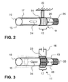
- Fig. 1 schematically illustrates the structure of a preferred embodiment of the device 1 for conveying a reducing agent 2, in particular urea-water solution.
- a motor vehicle 18 regularly has an internal combustion engine 19, for example a diesel engine, in which exhaust gas is produced, which is discharged via the exhaust pipe 20 into the environment.
- an exhaust treatment unit such as adsorbers, catalysts, filters, flow mixers and the same.
- an SCR catalytic converter 21 is illustrated, which converts the reducing agent mixed with the exhaust gas downstream, so that the undesirable nitrogen oxides are removed from the exhaust gas (SCR method).
- the device 1 is now shown centrally.
- the storage means 3 is shown in the manner of a tank in which the liquid reducing agent 2, here urea-water solution, is stored.
- the reducing agent 2 is conveyed out of the storage means 3, namely using the conveyor 4.
- the conveyor 4, in particular a diaphragm pump sucks the reducing agent 2 from the storage means 3 by a release agent 8 in the manner of a filter, the is positioned in the conduit 10 between storage means 3 and conveyor 4.
- the reducing agent is conveyed towards the outlet means 9, for example an injection nozzle, when reducing agent 2 is to be introduced into the exhaust gas conduit 20.
- a deflection means 6 is provided between the conveying means 4 and the outlet means 9. This can serve, in particular, to reduce the pressure of the reducing agent 2 within the conduit means 10 between the conveying means 4 and the outlet means 9 if necessary, when the apparatus 1 is not in operation.
- the reducing agent present in this conduit 10 can be transferred back into the storage means 3 via a return 5 and suitable conduit means 10.
- the conduit means 10 between conveying means 4 and deflection means 6 comprises a detection means 7, for example a pressure sensor.
- the conduit means 10 is designed with a thermal bridge 14, which is externally positioned on the wall 15 positively and in heat-conducting contact with the conduit means 10.
- This thermal bridge 10 for example, in the manner of a clamp, is also connected to a cold point 22, so in particular in thermal engineering contact.
- this very cold point 22 cools down quickly, thus removing the heat from the zone 12 of the conduit means 10.
- an earlier solidification or freezing of the reducing agent is achieved in this zone 12.
- This leads to the fact that the pressure build-up towards the connection 25 to the adjacent pressure-sensitive element (not shown here) remains small due to the short distance 26. Instead, the pressure build-up in the direction of the freezing direction 24.
- the slowed freezing adjacent to the zone 12 and opposite to the terminal 25 is improved in that there is a thermal insulation 17 is provided.
- the zone 12 is in this case designed with a radiator 23, which is also positioned positively and in particular in heat conductive contact with the conduit means 10.
- the radiator 23 has a plurality of cooling fins increasing the outer surface 13. Also in this way an early freezing of the reducing agent in the conduit means 10 in the region of the zone 12 is motivated.
- the zone 12 is preferably formed directly on the connection 25, for example with a maximum distance 26 of at most 50 mm.
- conduit means 10 are formed with a flexible wall 15.
- the flexible wall 15 can compensate for the increase in volume by widening its cross-section.
- a compensation volume can be created.
- conduit means 10 have been completely frozen, it is also advantageous to ensure a rapid liquefaction of the reducing agent.
Landscapes
- Chemical & Material Sciences (AREA)
- Engineering & Computer Science (AREA)
- Chemical Kinetics & Catalysis (AREA)
- Health & Medical Sciences (AREA)
- Combustion & Propulsion (AREA)
- Toxicology (AREA)
- Mechanical Engineering (AREA)
- General Engineering & Computer Science (AREA)
- Biomedical Technology (AREA)
- Environmental & Geological Engineering (AREA)
- Analytical Chemistry (AREA)
- General Chemical & Material Sciences (AREA)
- Oil, Petroleum & Natural Gas (AREA)
- Exhaust Gas After Treatment (AREA)
- Feeding, Discharge, Calcimining, Fusing, And Gas-Generation Devices (AREA)
- Cooling Or The Like Of Electrical Apparatus (AREA)
Priority Applications (1)
| Application Number | Priority Date | Filing Date | Title |
|---|---|---|---|
| PL09741986T PL2283214T3 (pl) | 2008-05-09 | 2009-04-23 | Urządzenie do transportu czynnika redukującego i sposób wytwarzania pojazdu mechanicznego |
Applications Claiming Priority (2)
| Application Number | Priority Date | Filing Date | Title |
|---|---|---|---|
| DE102008022991A DE102008022991A1 (de) | 2008-05-09 | 2008-05-09 | Vorrichtung zur Förderung eines Reduktionsmittels und Verfahren zur Herstellung eines Kraftfahrzeuges |
| PCT/EP2009/054910 WO2009135768A1 (de) | 2008-05-09 | 2009-04-23 | Vorrichtung zur förderung eines reduktionsmittels und verfahren zur herstellung eines kraftfahrzeuges |
Publications (2)
| Publication Number | Publication Date |
|---|---|
| EP2283214A1 EP2283214A1 (de) | 2011-02-16 |
| EP2283214B1 true EP2283214B1 (de) | 2012-06-20 |
Family
ID=40941470
Family Applications (1)
| Application Number | Title | Priority Date | Filing Date |
|---|---|---|---|
| EP09741986A Active EP2283214B1 (de) | 2008-05-09 | 2009-04-23 | Vorrichtung zur förderung eines reduktionsmittels und verfahren zur herstellung eines kraftfahrzeuges |
Country Status (11)
| Country | Link |
|---|---|
| US (1) | US8978361B2 (ru) |
| EP (1) | EP2283214B1 (ru) |
| JP (1) | JP5469162B2 (ru) |
| KR (2) | KR20110009692A (ru) |
| CN (1) | CN102016251B (ru) |
| DE (1) | DE102008022991A1 (ru) |
| DK (1) | DK2283214T3 (ru) |
| ES (1) | ES2389236T3 (ru) |
| PL (1) | PL2283214T3 (ru) |
| RU (1) | RU2496994C2 (ru) |
| WO (1) | WO2009135768A1 (ru) |
Families Citing this family (26)
| Publication number | Priority date | Publication date | Assignee | Title |
|---|---|---|---|---|
| DE102009039735A1 (de) | 2009-09-02 | 2011-03-03 | Emitec Gesellschaft Für Emissionstechnologie Mbh | Fördervorrichtung für ein Reduktionsmittel mit Kompensationselement |
| US8359842B2 (en) * | 2010-01-21 | 2013-01-29 | Emcon Technologies Llc | Airless fuel delivery system |
| DE102010054912B4 (de) * | 2010-12-17 | 2024-07-25 | Daimler Truck AG | Dosieranordnung und Verfahren zum Betreiben einer Dosieranordnung |
| DE102011010640A1 (de) * | 2011-02-09 | 2012-08-09 | Emitec France S.A.S | Fördereinheit zur Förderung von Reduktionsmittel |
| DE102011081628A1 (de) * | 2011-08-26 | 2013-02-28 | Robert Bosch Gmbh | Dosiersystem für ein flüssiges Reduktionsmittel |
| DE102011116335A1 (de) | 2011-10-19 | 2013-04-25 | Emitec France S.A.S | Fördervorrichtung mit Einfrierschutz |
| DE102011120457A1 (de) | 2011-12-07 | 2013-06-13 | Emitec Gesellschaft Für Emissionstechnologie Mbh | Einspritzvorrichtung zur Zugabe eines flüssigen Additivs |
| DE102012004726A1 (de) * | 2012-03-07 | 2013-09-12 | Emitec Gesellschaft Für Emissionstechnologie Mbh | Fördereinheit für ein flüssiges Additiv |
| SE1250265A1 (sv) * | 2012-03-20 | 2013-09-21 | Scania Cv Ab | Förfarande vid ett SCR-system och ett SCR-system |
| FR2995831B1 (fr) * | 2012-09-25 | 2014-08-29 | Renault Sa | Implantation de pipe de reservoir d'uree dans un vehicule utilitaire a moteur diesel et vehicule correspondant |
| DE102012020039B4 (de) | 2012-10-12 | 2015-02-19 | Kautex Textron Gmbh & Co. Kg | Einrichtung zur Bevorratung und Förderung eines Additivs zur katalytischen Abgasentstickung an einem Kfz |
| DE102013201537B4 (de) * | 2013-01-30 | 2021-10-14 | Mtu Friedrichshafen Gmbh | Zuführsystem für ein Medium |
| US9458746B2 (en) * | 2013-03-01 | 2016-10-04 | Cummins Emission Solutions Inc. | Systems and techniques for heating urea injection systems |
| US8959903B2 (en) * | 2013-03-01 | 2015-02-24 | Cummins Emission Solutions Inc. | Systems and techniques for heating urea injection systems |
| DE102013108505A1 (de) * | 2013-08-07 | 2015-03-05 | Emitec Denmark A/S | Verfahren zum Bestimmen der Qualität von Reduktionsmittel |
| FR3014704B1 (fr) * | 2013-12-12 | 2017-04-28 | Delphi Tech Holding S A R L | Dispositif de declenchement d’un signal electrique pour filtre a solution aqueuse |
| JP6162747B2 (ja) * | 2015-05-28 | 2017-07-12 | トヨタ自動車株式会社 | 添加剤供給装置 |
| DE102015212579A1 (de) * | 2015-07-06 | 2017-01-12 | Robert Bosch Gmbh | Reagenzmittel-Dosiersystem, Steuergerät, Steuergeräteprogramm und Steuergeräteprogrammprodukt |
| RU2612306C1 (ru) * | 2015-12-17 | 2017-03-06 | Федеральное государственное унитарное предприятие "Центральный ордена Трудового Красного Знамени научно-исследовательский автомобильный и автомоторный институт "НАМИ" | Устройство очистки отработавших газов двигателя транспортного средства |
| US9915185B2 (en) | 2016-02-17 | 2018-03-13 | Caterpillar Inc. | Injector mounting assembly |
| FR3053081B1 (fr) * | 2016-06-23 | 2018-07-13 | Akwel | Circuit de depollution a uree comprenant un clapet a double siege assurant selectivement le degazage ou la recirculation de la solution aqueuse d’uree |
| SE542040C2 (en) | 2016-10-26 | 2020-02-18 | Scania Cv Ab | An exhaust additive distribution device attached to a turbocharger turbine and an exhaust additive dosing system including such a distribution device |
| CN108223086B (zh) * | 2017-12-20 | 2020-06-09 | 江苏大学 | 一种利用汽车尾气温差发电对scr尿素供给管路加热系统 |
| DE102018216929A1 (de) * | 2018-10-02 | 2020-04-02 | Continental Automotive Gmbh | Heizvorrichtung zum Einbau in einen Fahrzeugtank für Reduktionsmittel und Fahrzeugtank |
| US11268417B2 (en) | 2019-06-26 | 2022-03-08 | Cummins Emission Solutions Inc. | Liquid only lance injector |
| DE102019210897A1 (de) * | 2019-07-23 | 2021-01-28 | Robert Bosch Gmbh | Abgasnachbehandlungssystem für eine Brennkraftmaschine |
Family Cites Families (17)
| Publication number | Priority date | Publication date | Assignee | Title |
|---|---|---|---|---|
| GB8606641D0 (en) * | 1986-03-18 | 1986-04-23 | British Petroleum Co Plc | Testing device |
| DE19738859A1 (de) * | 1997-09-05 | 1999-03-11 | Bosch Gmbh Robert | Gemischabgabevorrichtung |
| DE19806265C5 (de) * | 1998-02-16 | 2004-07-22 | Siemens Ag | Dosiersystem |
| DE19819579C1 (de) * | 1998-04-30 | 1999-09-30 | Siemens Ag | Verfahren und Vorrichtung zur Abgasnachbehandlung für eine mit einem SCR-Katalysator ausgestattete Brennkraftmaschine |
| DE19919426C1 (de) * | 1999-04-28 | 2000-03-30 | Siemens Ag | Ventilaufnahmevorrichtung für ein Dosierventil einer Abgasnachbehandlungsanlage |
| DE10047516A1 (de) * | 2000-09-22 | 2002-04-18 | Bosch Gmbh Robert | Verfahren und Vorrichtung zur Dosierung eines Reduktionsmittels zur Entfernung von Stickoxiden aus Abgasen |
| DE10324482B4 (de) * | 2003-05-30 | 2014-08-21 | Robert Bosch Gmbh | Vorrichtung zur Dosierung eines Reduktionsmittels zum Abgas eines Verbrennungsmotors |
| US7614213B2 (en) * | 2003-09-19 | 2009-11-10 | Nissan Diesel Motor Co., Ltd. | Engine exhaust emission purification apparatus |
| DE102004025062B4 (de) | 2004-05-18 | 2006-09-14 | Hydraulik-Ring Gmbh | Gefriertaugliches Dosierventil |
| DE102004026866A1 (de) * | 2004-06-02 | 2005-12-22 | Man Nutzfahrzeuge Ag | Verfahren und Vorrichtung zum Beheizen eines in einem Behälter eines Kraftfahrzeugs mitgeführten Reduktionsmittels zur Abgasnachbehandlung |
| US7594393B2 (en) * | 2004-09-07 | 2009-09-29 | Robert Bosch Gmbh | Apparatus for introducing a reducing agent into the exhaust of an internal combustion engine |
| DE102004046881A1 (de) * | 2004-09-28 | 2006-04-13 | Robert Bosch Gmbh | Zuführsystem für ein Medium, insbesondere zur Behandlung von Abgasen einer Brennkraftmaschine, Abgasreinigungsvorrichtung und Verfahren zum Betreiben eines Zuführsystems |
| DE102004062603B3 (de) * | 2004-12-24 | 2006-07-27 | Eichenauer Heizelemente Gmbh & Co. Kg | Harnstoff-Dosiersystem für einen Abgasreinigungskatalysator eines Kfz und Ringheizung für ein solches Harnstoff-Dosiersystem |
| DE102005031510B4 (de) * | 2005-07-06 | 2020-06-18 | Daimler Ag | Vorratsbehälter eines Kraftfahrzeugs |
| DE102005061145A1 (de) * | 2005-12-21 | 2007-06-28 | Robert Bosch Gmbh | Abgasnachbehandlungsvorrichtung |
| DE102006040411A1 (de) * | 2006-08-29 | 2008-03-06 | Purem Abgassysteme Gmbh & Co. Kg | Reduktionsmitteldosiersystem |
| JP4706660B2 (ja) * | 2007-04-10 | 2011-06-22 | 株式会社デンソー | 還元剤供給装置 |
-
2008
- 2008-05-09 DE DE102008022991A patent/DE102008022991A1/de not_active Withdrawn
-
2009
- 2009-04-23 JP JP2011507865A patent/JP5469162B2/ja active Active
- 2009-04-23 WO PCT/EP2009/054910 patent/WO2009135768A1/de active Application Filing
- 2009-04-23 PL PL09741986T patent/PL2283214T3/pl unknown
- 2009-04-23 CN CN200980116640.6A patent/CN102016251B/zh active Active
- 2009-04-23 KR KR1020107027549A patent/KR20110009692A/ko not_active IP Right Cessation
- 2009-04-23 ES ES09741986T patent/ES2389236T3/es active Active
- 2009-04-23 KR KR1020137011281A patent/KR101279672B1/ko active IP Right Grant
- 2009-04-23 RU RU2010150000/06A patent/RU2496994C2/ru active
- 2009-04-23 DK DK09741986.5T patent/DK2283214T3/da active
- 2009-04-23 EP EP09741986A patent/EP2283214B1/de active Active
-
2010
- 2010-11-09 US US12/942,470 patent/US8978361B2/en active Active
Also Published As
| Publication number | Publication date |
|---|---|
| CN102016251B (zh) | 2014-07-30 |
| EP2283214A1 (de) | 2011-02-16 |
| KR20110009692A (ko) | 2011-01-28 |
| DE102008022991A1 (de) | 2009-11-12 |
| KR101279672B1 (ko) | 2013-06-27 |
| KR20130054456A (ko) | 2013-05-24 |
| RU2010150000A (ru) | 2012-08-20 |
| JP2011523689A (ja) | 2011-08-18 |
| WO2009135768A1 (de) | 2009-11-12 |
| ES2389236T3 (es) | 2012-10-24 |
| RU2496994C2 (ru) | 2013-10-27 |
| US20110113765A1 (en) | 2011-05-19 |
| DK2283214T3 (da) | 2012-10-01 |
| US8978361B2 (en) | 2015-03-17 |
| CN102016251A (zh) | 2011-04-13 |
| PL2283214T3 (pl) | 2012-11-30 |
| JP5469162B2 (ja) | 2014-04-09 |
Similar Documents
| Publication | Publication Date | Title |
|---|---|---|
| EP2283214B1 (de) | Vorrichtung zur förderung eines reduktionsmittels und verfahren zur herstellung eines kraftfahrzeuges | |
| DE102007000526B4 (de) | Abgasreinigungsvorrichtung für eine Kraftmaschine | |
| EP2344735B1 (de) | Komponententräger für ein dosiersystem | |
| DE10324482B4 (de) | Vorrichtung zur Dosierung eines Reduktionsmittels zum Abgas eines Verbrennungsmotors | |
| EP2758644B1 (de) | Wärmetauscher für eine dosiereinheit einer scr-abgasnachbehandlungseinrichtung | |
| EP2582937A1 (de) | Vorrichtung zur förderung von flüssigem reduktionsmittel | |
| EP2524119A1 (de) | Vorrichtung mit einem tank und einer fördereinheit für reduktionsmittel | |
| DE102006046899A1 (de) | Tank zur Bevorratung eines Reduktionsmittels | |
| DE102011086017A1 (de) | Dosiermodul | |
| DE102007047862A1 (de) | Fluiderwärmungsvorrichtung und Abgasreinigungsgerät | |
| EP2823164B1 (de) | Vorrichtung zur bereitstellung von flüssigem additiv | |
| WO2011141502A1 (de) | Tank zur bevorratung eines betriebsstoffs | |
| DE102010024021A1 (de) | Vorrichtung zur Bereitstellung eines Reduktionsmittels mit Systemheizung | |
| EP2929155B1 (de) | Verfahren zum betrieb einer vorrichtung zur bereitstellung eines flüssigen additivs | |
| EP1741888A1 (de) | Vorratsbehälter eines Kraftfahrzeugs | |
| EP2414646B1 (de) | Einspritzeinrichtung für harnstoffwasserlösung | |
| DE102008061471B4 (de) | Verfahren zum Abschmelzen und/oder Erwärmen einer Reduktionsmittelflüssigkeit in einem SCR-Abgasnachbehandlungssystem | |
| DE102008042954A1 (de) | Dosiersystem für ein flüssiges Medium, insbesondere Harnstoff-Wasser-Lösung | |
| DE102010039060A1 (de) | Versorgungssystem für Brennkraftmaschinen mit isoliertem Vorratsbehälter | |
| EP3212906B1 (de) | Fördereinheit zur förderung einer flüssigkeit | |
| DE102013225360A1 (de) | Heizvorrichtung | |
| EP3135876B1 (de) | Vorrichtung zur abgasnachbehandlung | |
| WO2019029881A1 (de) | Tankeinrichtung für abgasnachbehandlungssystem | |
| DE102016209944A1 (de) | Verfahren zum Betreiben eines Förder- und Dosiersystems für die Reduktionsmittellösung eines SCR-Katalysators | |
| DE102018218933A1 (de) | Entnahmeeinrichtung für ein flüssiges Medium, Tankeinrichtung |
Legal Events
| Date | Code | Title | Description |
|---|---|---|---|
| PUAI | Public reference made under article 153(3) epc to a published international application that has entered the european phase |
Free format text: ORIGINAL CODE: 0009012 |
|
| 17P | Request for examination filed |
Effective date: 20101021 |
|
| AK | Designated contracting states |
Kind code of ref document: A1 Designated state(s): AT BE BG CH CY CZ DE DK EE ES FI FR GB GR HR HU IE IS IT LI LT LU LV MC MK MT NL NO PL PT RO SE SI SK TR |
|
| AX | Request for extension of the european patent |
Extension state: AL BA RS |
|
| 17Q | First examination report despatched |
Effective date: 20110411 |
|
| DAX | Request for extension of the european patent (deleted) | ||
| GRAP | Despatch of communication of intention to grant a patent |
Free format text: ORIGINAL CODE: EPIDOSNIGR1 |
|
| GRAS | Grant fee paid |
Free format text: ORIGINAL CODE: EPIDOSNIGR3 |
|
| GRAA | (expected) grant |
Free format text: ORIGINAL CODE: 0009210 |
|
| AK | Designated contracting states |
Kind code of ref document: B1 Designated state(s): AT BE BG CH CY CZ DE DK EE ES FI FR GB GR HR HU IE IS IT LI LT LU LV MC MK MT NL NO PL PT RO SE SI SK TR |
|
| REG | Reference to a national code |
Ref country code: GB Ref legal event code: FG4D Free format text: NOT ENGLISH |
|
| REG | Reference to a national code |
Ref country code: CH Ref legal event code: EP |
|
| REG | Reference to a national code |
Ref country code: AT Ref legal event code: REF Ref document number: 563200 Country of ref document: AT Kind code of ref document: T Effective date: 20120715 |
|
| REG | Reference to a national code |
Ref country code: IE Ref legal event code: FG4D Free format text: LANGUAGE OF EP DOCUMENT: GERMAN |
|
| REG | Reference to a national code |
Ref country code: DE Ref legal event code: R096 Ref document number: 502009003874 Country of ref document: DE Effective date: 20120816 |
|
| REG | Reference to a national code |
Ref country code: DK Ref legal event code: T3 |
|
| REG | Reference to a national code |
Ref country code: SE Ref legal event code: TRGR |
|
| REG | Reference to a national code |
Ref country code: ES Ref legal event code: FG2A Ref document number: 2389236 Country of ref document: ES Kind code of ref document: T3 Effective date: 20121024 |
|
| PG25 | Lapsed in a contracting state [announced via postgrant information from national office to epo] |
Ref country code: NO Free format text: LAPSE BECAUSE OF FAILURE TO SUBMIT A TRANSLATION OF THE DESCRIPTION OR TO PAY THE FEE WITHIN THE PRESCRIBED TIME-LIMIT Effective date: 20120920 Ref country code: LT Free format text: LAPSE BECAUSE OF FAILURE TO SUBMIT A TRANSLATION OF THE DESCRIPTION OR TO PAY THE FEE WITHIN THE PRESCRIBED TIME-LIMIT Effective date: 20120620 Ref country code: FI Free format text: LAPSE BECAUSE OF FAILURE TO SUBMIT A TRANSLATION OF THE DESCRIPTION OR TO PAY THE FEE WITHIN THE PRESCRIBED TIME-LIMIT Effective date: 20120620 |
|
| REG | Reference to a national code |
Ref country code: NL Ref legal event code: VDEP Effective date: 20120620 |
|
| REG | Reference to a national code |
Ref country code: LT Ref legal event code: MG4D Effective date: 20120620 |
|
| PG25 | Lapsed in a contracting state [announced via postgrant information from national office to epo] |
Ref country code: LV Free format text: LAPSE BECAUSE OF FAILURE TO SUBMIT A TRANSLATION OF THE DESCRIPTION OR TO PAY THE FEE WITHIN THE PRESCRIBED TIME-LIMIT Effective date: 20120620 Ref country code: HR Free format text: LAPSE BECAUSE OF FAILURE TO SUBMIT A TRANSLATION OF THE DESCRIPTION OR TO PAY THE FEE WITHIN THE PRESCRIBED TIME-LIMIT Effective date: 20120620 Ref country code: GR Free format text: LAPSE BECAUSE OF FAILURE TO SUBMIT A TRANSLATION OF THE DESCRIPTION OR TO PAY THE FEE WITHIN THE PRESCRIBED TIME-LIMIT Effective date: 20120921 Ref country code: SI Free format text: LAPSE BECAUSE OF FAILURE TO SUBMIT A TRANSLATION OF THE DESCRIPTION OR TO PAY THE FEE WITHIN THE PRESCRIBED TIME-LIMIT Effective date: 20120620 |
|
| REG | Reference to a national code |
Ref country code: PL Ref legal event code: T3 |
|
| PG25 | Lapsed in a contracting state [announced via postgrant information from national office to epo] |
Ref country code: RO Free format text: LAPSE BECAUSE OF FAILURE TO SUBMIT A TRANSLATION OF THE DESCRIPTION OR TO PAY THE FEE WITHIN THE PRESCRIBED TIME-LIMIT Effective date: 20120620 Ref country code: EE Free format text: LAPSE BECAUSE OF FAILURE TO SUBMIT A TRANSLATION OF THE DESCRIPTION OR TO PAY THE FEE WITHIN THE PRESCRIBED TIME-LIMIT Effective date: 20120620 Ref country code: CY Free format text: LAPSE BECAUSE OF FAILURE TO SUBMIT A TRANSLATION OF THE DESCRIPTION OR TO PAY THE FEE WITHIN THE PRESCRIBED TIME-LIMIT Effective date: 20120620 Ref country code: IS Free format text: LAPSE BECAUSE OF FAILURE TO SUBMIT A TRANSLATION OF THE DESCRIPTION OR TO PAY THE FEE WITHIN THE PRESCRIBED TIME-LIMIT Effective date: 20121020 Ref country code: SK Free format text: LAPSE BECAUSE OF FAILURE TO SUBMIT A TRANSLATION OF THE DESCRIPTION OR TO PAY THE FEE WITHIN THE PRESCRIBED TIME-LIMIT Effective date: 20120620 Ref country code: CZ Free format text: LAPSE BECAUSE OF FAILURE TO SUBMIT A TRANSLATION OF THE DESCRIPTION OR TO PAY THE FEE WITHIN THE PRESCRIBED TIME-LIMIT Effective date: 20120620 |
|
| PG25 | Lapsed in a contracting state [announced via postgrant information from national office to epo] |
Ref country code: PT Free format text: LAPSE BECAUSE OF FAILURE TO SUBMIT A TRANSLATION OF THE DESCRIPTION OR TO PAY THE FEE WITHIN THE PRESCRIBED TIME-LIMIT Effective date: 20121022 |
|
| PG25 | Lapsed in a contracting state [announced via postgrant information from national office to epo] |
Ref country code: NL Free format text: LAPSE BECAUSE OF FAILURE TO SUBMIT A TRANSLATION OF THE DESCRIPTION OR TO PAY THE FEE WITHIN THE PRESCRIBED TIME-LIMIT Effective date: 20120620 |
|
| PLBE | No opposition filed within time limit |
Free format text: ORIGINAL CODE: 0009261 |
|
| STAA | Information on the status of an ep patent application or granted ep patent |
Free format text: STATUS: NO OPPOSITION FILED WITHIN TIME LIMIT |
|
| 26N | No opposition filed |
Effective date: 20130321 |
|
| REG | Reference to a national code |
Ref country code: DE Ref legal event code: R097 Ref document number: 502009003874 Country of ref document: DE Effective date: 20130321 |
|
| PG25 | Lapsed in a contracting state [announced via postgrant information from national office to epo] |
Ref country code: BG Free format text: LAPSE BECAUSE OF FAILURE TO SUBMIT A TRANSLATION OF THE DESCRIPTION OR TO PAY THE FEE WITHIN THE PRESCRIBED TIME-LIMIT Effective date: 20120920 |
|
| BERE | Be: lapsed |
Owner name: EMITEC G.- FUR EMISSIONSTECHNOLOGIE MBH Effective date: 20130430 |
|
| PG25 | Lapsed in a contracting state [announced via postgrant information from national office to epo] |
Ref country code: MC Free format text: LAPSE BECAUSE OF FAILURE TO SUBMIT A TRANSLATION OF THE DESCRIPTION OR TO PAY THE FEE WITHIN THE PRESCRIBED TIME-LIMIT Effective date: 20120620 |
|
| REG | Reference to a national code |
Ref country code: CH Ref legal event code: PL |
|
| REG | Reference to a national code |
Ref country code: IE Ref legal event code: MM4A |
|
| PG25 | Lapsed in a contracting state [announced via postgrant information from national office to epo] |
Ref country code: CH Free format text: LAPSE BECAUSE OF NON-PAYMENT OF DUE FEES Effective date: 20130430 Ref country code: LI Free format text: LAPSE BECAUSE OF NON-PAYMENT OF DUE FEES Effective date: 20130430 Ref country code: BE Free format text: LAPSE BECAUSE OF NON-PAYMENT OF DUE FEES Effective date: 20130430 |
|
| PG25 | Lapsed in a contracting state [announced via postgrant information from national office to epo] |
Ref country code: IE Free format text: LAPSE BECAUSE OF NON-PAYMENT OF DUE FEES Effective date: 20130423 |
|
| PG25 | Lapsed in a contracting state [announced via postgrant information from national office to epo] |
Ref country code: MT Free format text: LAPSE BECAUSE OF FAILURE TO SUBMIT A TRANSLATION OF THE DESCRIPTION OR TO PAY THE FEE WITHIN THE PRESCRIBED TIME-LIMIT Effective date: 20120620 |
|
| REG | Reference to a national code |
Ref country code: AT Ref legal event code: MM01 Ref document number: 563200 Country of ref document: AT Kind code of ref document: T Effective date: 20140423 |
|
| PG25 | Lapsed in a contracting state [announced via postgrant information from national office to epo] |
Ref country code: TR Free format text: LAPSE BECAUSE OF FAILURE TO SUBMIT A TRANSLATION OF THE DESCRIPTION OR TO PAY THE FEE WITHIN THE PRESCRIBED TIME-LIMIT Effective date: 20120620 |
|
| PG25 | Lapsed in a contracting state [announced via postgrant information from national office to epo] |
Ref country code: HU Free format text: LAPSE BECAUSE OF FAILURE TO SUBMIT A TRANSLATION OF THE DESCRIPTION OR TO PAY THE FEE WITHIN THE PRESCRIBED TIME-LIMIT; INVALID AB INITIO Effective date: 20090423 Ref country code: MK Free format text: LAPSE BECAUSE OF FAILURE TO SUBMIT A TRANSLATION OF THE DESCRIPTION OR TO PAY THE FEE WITHIN THE PRESCRIBED TIME-LIMIT Effective date: 20120620 Ref country code: LU Free format text: LAPSE BECAUSE OF NON-PAYMENT OF DUE FEES Effective date: 20130423 |
|
| PG25 | Lapsed in a contracting state [announced via postgrant information from national office to epo] |
Ref country code: AT Free format text: LAPSE BECAUSE OF NON-PAYMENT OF DUE FEES Effective date: 20140423 |
|
| REG | Reference to a national code |
Ref country code: DE Ref legal event code: R081 Ref document number: 502009003874 Country of ref document: DE Owner name: VITESCO TECHNOLOGIES GMBH, DE Free format text: FORMER OWNER: EMITEC GESELLSCHAFT FUER EMISSIONSTECHNOLOGIE MBH, 53797 LOHMAR, DE Ref country code: DE Ref legal event code: R082 Ref document number: 502009003874 Country of ref document: DE Ref country code: DE Ref legal event code: R081 Ref document number: 502009003874 Country of ref document: DE Owner name: CONTINENTAL AUTOMOTIVE GMBH, DE Free format text: FORMER OWNER: EMITEC GESELLSCHAFT FUER EMISSIONSTECHNOLOGIE MBH, 53797 LOHMAR, DE |
|
| REG | Reference to a national code |
Ref country code: FR Ref legal event code: PLFP Year of fee payment: 8 |
|
| REG | Reference to a national code |
Ref country code: GB Ref legal event code: 732E Free format text: REGISTERED BETWEEN 20160331 AND 20160406 |
|
| PGFP | Annual fee paid to national office [announced via postgrant information from national office to epo] |
Ref country code: GB Payment date: 20160421 Year of fee payment: 8 Ref country code: ES Payment date: 20160414 Year of fee payment: 8 |
|
| PGFP | Annual fee paid to national office [announced via postgrant information from national office to epo] |
Ref country code: DK Payment date: 20160420 Year of fee payment: 8 Ref country code: PL Payment date: 20160421 Year of fee payment: 8 |
|
| REG | Reference to a national code |
Ref country code: FR Ref legal event code: PLFP Year of fee payment: 9 |
|
| REG | Reference to a national code |
Ref country code: DK Ref legal event code: EBP Effective date: 20170430 |
|
| GBPC | Gb: european patent ceased through non-payment of renewal fee |
Effective date: 20170423 |
|
| PG25 | Lapsed in a contracting state [announced via postgrant information from national office to epo] |
Ref country code: GB Free format text: LAPSE BECAUSE OF NON-PAYMENT OF DUE FEES Effective date: 20170423 |
|
| REG | Reference to a national code |
Ref country code: FR Ref legal event code: PLFP Year of fee payment: 10 |
|
| PG25 | Lapsed in a contracting state [announced via postgrant information from national office to epo] |
Ref country code: DK Free format text: LAPSE BECAUSE OF NON-PAYMENT OF DUE FEES Effective date: 20170430 |
|
| REG | Reference to a national code |
Ref country code: ES Ref legal event code: FD2A Effective date: 20180703 |
|
| PG25 | Lapsed in a contracting state [announced via postgrant information from national office to epo] |
Ref country code: ES Free format text: LAPSE BECAUSE OF NON-PAYMENT OF DUE FEES Effective date: 20170424 |
|
| PG25 | Lapsed in a contracting state [announced via postgrant information from national office to epo] |
Ref country code: PL Free format text: LAPSE BECAUSE OF NON-PAYMENT OF DUE FEES Effective date: 20170423 |
|
| REG | Reference to a national code |
Ref country code: DE Ref legal event code: R081 Ref document number: 502009003874 Country of ref document: DE Owner name: VITESCO TECHNOLOGIES GMBH, DE Free format text: FORMER OWNER: CONTINENTAL AUTOMOTIVE GMBH, 30165 HANNOVER, DE |
|
| REG | Reference to a national code |
Ref country code: DE Ref legal event code: R081 Ref document number: 502009003874 Country of ref document: DE Owner name: VITESCO TECHNOLOGIES GMBH, DE Free format text: FORMER OWNER: VITESCO TECHNOLOGIES GMBH, 30165 HANNOVER, DE |
|
| REG | Reference to a national code |
Ref country code: DE Ref legal event code: R084 Ref document number: 502009003874 Country of ref document: DE |
|
| P01 | Opt-out of the competence of the unified patent court (upc) registered |
Effective date: 20230830 |
|
| PGFP | Annual fee paid to national office [announced via postgrant information from national office to epo] |
Ref country code: DE Payment date: 20240430 Year of fee payment: 16 |
|
| PGFP | Annual fee paid to national office [announced via postgrant information from national office to epo] |
Ref country code: IT Payment date: 20240424 Year of fee payment: 16 Ref country code: FR Payment date: 20240426 Year of fee payment: 16 |
|
| PGFP | Annual fee paid to national office [announced via postgrant information from national office to epo] |
Ref country code: SE Payment date: 20240418 Year of fee payment: 16 |