EP2282697B1 - Verfahren zur konzeption einer massgeschneiderten zahnprothese mithilfe digitaler patientenbilder - Google Patents
Verfahren zur konzeption einer massgeschneiderten zahnprothese mithilfe digitaler patientenbilder Download PDFInfo
- Publication number
- EP2282697B1 EP2282697B1 EP09788791.3A EP09788791A EP2282697B1 EP 2282697 B1 EP2282697 B1 EP 2282697B1 EP 09788791 A EP09788791 A EP 09788791A EP 2282697 B1 EP2282697 B1 EP 2282697B1
- Authority
- EP
- European Patent Office
- Prior art keywords
- patient
- denture
- tooth
- shade
- dental
- Prior art date
- Legal status (The legal status is an assumption and is not a legal conclusion. Google has not performed a legal analysis and makes no representation as to the accuracy of the status listed.)
- Active
Links
Images


Classifications
-
- A—HUMAN NECESSITIES
- A61—MEDICAL OR VETERINARY SCIENCE; HYGIENE
- A61C—DENTISTRY; APPARATUS OR METHODS FOR ORAL OR DENTAL HYGIENE
- A61C13/00—Dental prostheses; Making same
- A61C13/0003—Making bridge-work, inlays, implants or the like
- A61C13/0004—Computer-assisted sizing or machining of dental prostheses
-
- A—HUMAN NECESSITIES
- A61—MEDICAL OR VETERINARY SCIENCE; HYGIENE
- A61C—DENTISTRY; APPARATUS OR METHODS FOR ORAL OR DENTAL HYGIENE
- A61C13/00—Dental prostheses; Making same
- A61C13/01—Palates or other bases or supports for the artificial teeth; Making same
-
- A—HUMAN NECESSITIES
- A61—MEDICAL OR VETERINARY SCIENCE; HYGIENE
- A61C—DENTISTRY; APPARATUS OR METHODS FOR ORAL OR DENTAL HYGIENE
- A61C9/00—Impression cups, i.e. impression trays; Impression methods
- A61C9/004—Means or methods for taking digitized impressions
- A61C9/0046—Data acquisition means or methods
-
- A—HUMAN NECESSITIES
- A61—MEDICAL OR VETERINARY SCIENCE; HYGIENE
- A61C—DENTISTRY; APPARATUS OR METHODS FOR ORAL OR DENTAL HYGIENE
- A61C13/00—Dental prostheses; Making same
- A61C13/08—Artificial teeth; Making same
Definitions
- the invention relates generally to methods for designing customized dental restorations and prostheses and particularly dentures.
- the methods involve taking digital photographs of the patient to be fitted with the restoration or prosthesis and transferring the photographs to a computer software program.
- the software program uses the photographs to make certain calculations that are translated into their corresponding anterior maxillary tooth mould forms.
- the program prompts the dental professional to select the desired materials and structure for the denture, such as denture tooth shade, tooth arrangement, patient ridge condition, occlusal scheme, and denture base. This information is used to generate a customized prescription for the denture.
- the resulting prescription is sent to a dental laboratory that manufactures the denture.
- dental prostheses or appliances to treat patients with lost teeth or tooth structure.
- prosthesis “restoration” “and “appliance” as used herein, it is meant a dental product that replaces or restores lost tooth structure, teeth, or oral tissue including, but not limited to, fillings, inlays, onlays, veneers, crowns, bridges, full dentures, removable partial dentures, relines of full and partial dentures, nightguards, occlusal splints, and the like.
- Common dental prostheses for full or partially edentulous patients include, for example, full dentures and partial dentures. The dentures are used to restore or replace the lost teeth.
- the partial denture includes a base having a partial set of embedded artificial teeth which rests in the edentulous space and is coupled to abutment teeth by clasps or other connectors.
- Full dentures are used to replace all of the patient's natural teeth.
- a full denture includes a base having a full set of embedded artificial teeth which fits over either the upper gum tissue or lower gum tissue.
- Partial dentures are designed to preserve any remaining teeth along with hard and soft oral tissue.
- the dentures must be functional.
- the denture should enhance the dental and facial aesthetics of the patient.
- the denture teeth should appear natural. However, it is often difficult to make form-fitting and comfortable dentures. The process is time-consuming requiring the patient to make several dental office visits. In many instance, the dentist must reshape and adjust the denture several times before the patient is satisfied.
- a dentist first takes impressions of a patient's dental anatomy.
- a paste-like material such as an alginate, is placed in a standard or custom-made impression tray.
- the dentist inserts the tray in the mouth of a patient and he/she bites down into the tray.
- Separate impression trays for the upper and lower dental arches are used.
- the dentist allows the impression material to harden and then removes the trays from the patient's mouth.
- the hardened impressions are finally sent to a dental laboratory.
- a dental technician prepares models of the upper/lower dental arches by pouring dental stone into the hardened impressions.
- the dental models After a release coating is applied to the dental models, they are placed in a conditioning oven and warmed. A polymerizable resin used to form the baseplate is molded over the warm models. Then, the resin-coated models are placed in a light-curing unit and irradiated with light to harden the baseplate resin. After the light-curing cycle has been completed, the models are removed from the unit and allowed to cool. The hardened baseplates are removed from the respective models. It is customary for the technician to mount wax occlusal rims over the baseplates. The resulting wax rim baseplates are returned to the dentist so they can be evaluated for fit and comfort in the patient's mouth. Then, the completed occlusal registration is articulated.
- artificial teeth are built on the processed baseplate and wax rims using a "lost wax" process.
- wax is applied to the baseplate and a set of artificial teeth is positioned in the wax.
- the processed baseplate, with completed tooth arrangement is placed in a flask containing an investing material. Then, the flask is heated to eliminate the wax. Upon melting, the wax flows out of the flask. Removing the wax from inside of the flask leaves an interior cavity having the shape of the denture.
- a polymerizable acrylic composition is "packed into” into the interior cavity of the flask. The acrylic composition is heated so that it bonds to the teeth and baseplate. When this acrylic composition cures and hardens, it will hold the artificial teeth in position.
- Jelonek US Patent 7,035,702 discloses a method for making dental restorations involving the steps of determining the geometrical and aesthetic constraints of the restoration. These constraints are inputted into a computer to mathematically select a recipe for producing the dental restoration. A database of materials and procedures for preparing the dental restoration is compiled. Then, a recipe for making the restoration is produced from the database based on inputted data.
- Taub, US Patent 7,33,874 discloses methods for designing and producing dental prostheses using a communication network between a dental clinic and dental laboratory.
- the system also includes a dental service center which is a separate entity from the dental laboratory.
- the service center generates a virtual 3D model of the patient's dentition from data obtained by scanning the teeth directly or by scanning a physical model of the teeth.
- the manufacturing of the prosthesis is shared between the service center and dental lab.
- the clinic sends instructions to the dental laboratory and service center.
- the data needed to produce the virtual 3D model is transmitted from the dental clinic or laboratory to the dental service center.
- a prescription specifying the teeth that are to be moved in the dental treatment as well as the final position of the teeth is sent to the service center.
- the service center uses software to make a virtual 3D model, which is used to determine the dental appliance needed. Finally, this information is sent to the dental lab which makes the appliance.
- the above-described systems may provide some advantages, but they are not used for designing and making dentures for edentulous patients, which present particular problems.
- the dentist in a conventional denture-making process, the dentist must manually measure the facial and oral dimensions of the patient, and selects artificial tooth colors, shades, and dimensions using manual tools such as tooth indicators, shade guides, and mould guides. Based on this information, the dentist sends a prescription for the denture to a dental laboratory. There are many variables to this process and the resulting prescription for the denture depends upon the techniques, skills, and experience level of the dental professionals. Some prescriptions will provide detailed information about the requested denture including patient's dental anatomy, baseplate materials, tooth dimensions and shapes, tooth color and shades, and the like. Other prescriptions will simply request the denture be made as the laboratory sees fit and will only provide information on the tooth shade.
- EP 1 707 928 A discloses an image processing system which performs colour reproduction computation processing and image judgement computation processing.
- US 6 261 248 B1 discloses a maxillary tooth dimension determining system for computing an ideal width and ideal height of the maxillary tooth of the client, using pupillary distance information.
- the methods and system of the present invention provides the dental professional with a new chair-side method for writing denture prescriptions.
- the dentist can use the system to generate detailed digital prescriptions including information on facial dimensions of the patient, tooth length, width and geometry, requested composition of the artificial teeth, edentulous ridge condition and occlusal registration of the patient, denture base materials, and color and shade of the artificial teeth.
- the resulting prescription can be sent by e-mail, paper mail, or facsimile to a dental laboratory that will manufacture the denture. This system is easy-to-use, consistent, and time-saving for the dentist.
- Step 1 the functional steps for designing and preparing a denture in accordance with one version of the invention are generally shown. Particularly, in Step 1, the dental practitioner takes at least one digital photograph of a patient's face and transfers the photograph to a computer software program.
- a digital imaging system which can be used in the system and method, is generally indicated at (10).
- Ordinary digital cameras (12) can be used to take color digital photographs of a patient (14). Preferably, only one color digital photograph of the patient's face is taken, the photograph being a frontal view (16). Additional color digital photographs, however, can be taken if needed. For example, a profile or side view photograph of the patient could be taken.
- the digital photographs are loaded in a software program which is loaded in a computer (20) that includes a user interface system such as keyboard and/or mouse (22).
- the software can be packaged in any conventional way, for example, as a compact disc (CD).
- the software provides the user with interface tools such as graphic icons, images, text, windows, menus, and other screen displays so he/she can navigate their way through the program and complete the steps required to generate a denture prescription.
- a grey screen reference sticker" (24) is placed on the forehead of the patient and a grey screen mouth shield” (26) is positioned inside the mouth of the patient.
- the sticker (24) and mouth shield (26) are used so that a grey screening and color balancing procedure can be performed as described further below.
- FIG. 3 a frontal view of a patient (14) wearing reference sticker (24) and mouth shield (26) is shown.
- the mouth shield (26) has a ribbon-like structure with notched portions (27a, 27b).
- the mouth shield (26) is made from a thin, soft, and flexible material.
- the mouth shield should have good dimensional stability and be sufficiently rigid so that it retains its position once it is placed inside of the mouth Suitable materials for making the mouth shield (26) include, but are not limited, to urethane foam and flexible wax-based sheets.
- the mouth shield (26) is designed to fit most patients and has a length in the range of about 70 to about 90 mm; width of about 25 to about 50 mm; and thickness of about 0.25 to about 3 mm.
- the mouth shield (26) is placed in the mouth of the patient (14) and folded over at notched portions (27a, 27b) so that it is tightly secured between the gums and lips. To adjust the fit of the mouth shield (26) for a given patient, scissors can be used to trim excess portions. As shown in FIG.
- the mouth shield (26) resembles an athletic mouth guard when positioned in the mouth of the patient (14).
- the removable reference sticker (24) is a paper or film material having an adhesive coated on its backside.
- the square-shaped sticker (24) generally measures about 1 cm x about 1 cm. The sticker (24) can be placed on the forehead of the patient and removed after the photographs have been taken.
- the color grey preferably is used for the reference sticker (24) and mouth shield (26), because it contrasts sharply with other skin colors and the patient would not normally be wearing any other grey object on his/her face when taking the photographs.
- grey screening the system checks to see which pixels in the input image (digital color photograph) are not grey and labels those pixels as “target” pixels.
- the software then blends the "input image” (patient's facial image, which is a collection of all target pixels) into a "destination image” that will appear on the computer monitor screen (21).
- the pixels in the grey areas are not labeled as target pixels and thus will not be blended in with the rest of the pixels constituting the facial features.
- chroma keying This technique of blending two images together after a color has been removed from one of the images can be referred to as chroma keying.
- voids will appear in the area of the forehead (where the grey screen sticker has been placed) and area of the mouth (where the grey screen mouth shield has been inserted).
- the software program first looks to the forehead area. Because the software knows the relative dimensions of the grey sticker (24), it can use this information to make key measurements of the forehead and other facial contours. In addition, the software fills in the voided mouth area with selected tooth shades and tooth forms per the methods discussed further below. That is, the practitioner can select a particular denture structure with artificial teeth and "drop" this picture into the open mouth area of the digital image. The resulting destination image with selected denture is shown to the patient. Thus, the patient can see the results of selecting a specific denture before the treatment plan is finalized. The patient can see how a particular denture structure will affect their overall appearance. The system is beneficial to the practitioner and patient, because it can simulate different treatment plans using different sets of artificial teeth.
- the software Upon receiving the digital image, the software automatically engages in color balancing to adjust the color of the captured digital image and generate a color balanced reproduction.
- Color balancing techniques are known in the digital imaging industry. Color balancing is needed, because colors in the captured digital image can shift resulting in an off-color image of the subject. Color shifting can be due to a variety of reasons, for example, shadows, lighting, and backdrops used when the digital image was taken. In the method of this invention, the colors of the facial image of the patient can become distorted; thus, color balancing of the image is needed.
- a selected artificial tooth set can be "dropped' into the image and a denture prescription can be generated as described in more detail below.
- the color of the selected "dropped in" tooth set is perceived correctly. That is, the color, shade, hue, brilliance, intensity, RGB values, and other characteristics of the tooth set and facial digital image match-up properly.
- This benefits the dental practitioner, because he/she is better able to select the most appropriate tooth shade with input from the patient. The practitioner and patient can better visualize which tooth shade is the most natural looking.
- a "green-screening" system can be used, wherein the reference sticker (24) and mouth shield (26) are green colored.
- a "green-screening" system is less preferred, because there can be problems with color balancing and the captured digital image may be off-color.
- the software In addition to the color balancing step, the software automatically formats the digital image to the correct size, and the formatted, color-balanced image appears on the monitor screen (21) so that the practitioner can view it easily.
- the software program identifies the key facial contours, for example, chin, temple, vertical midline, and horizontal plane across the pupils. It is important that vertical and horizontal reference planes of the patient's face be considered so that an aesthetically-pleasing denture with artificial teeth having proper occlusion can be made.
- the program identifies the vertical midline and horizontal plane across the pupils as shown in FIG. 5 .
- the dental practitioner can use the reference lines automatically provided by the program if they are acceptable.
- the practitioner can override the recommendations made by the program and mark key facial landmarks that they believe are more accurate.
- the program then provides a recommended face shape that the practitioner again has the ability to accept or override with his/her own selection.
- the program can include a "default" face shape. For example, the face shape, "square tapering" could be used as the default and this shape would be automatically entered if the user did not enter otherwise.
- the software automatically determines the width and length of the central incisor artificial teeth that will be used in the denture. The practitioner also has the ability to accept or decline these measurements and enter his/her own measurements. After all of the requested information has been entered and accepted, the program will provide the recommended maxillary anterior denture tooth mould forms to be used for making the artificial teeth as discussed further below.
- the dental practitioner next enters the color shade guide that will be used for determining the color and shade of the artificial teeth to be used in the finished denture.
- Standard dental shade guides are known in the dental industry and these guides can be used in the system of this invention.
- PortraitTM IPNTM, Trubyte BioformTM IPNTM, or BioblendTM IPNTM, shade guides available from Dentsply International (York, PA) can be used.
- Other suitable shade guides include Vita ClassicalTM and Vita 3-DTM shade guides available from Vita Zahnfabrik H. Rauter GmbH & Co. KG (Germany).
- the software can provide the practitioner with at least two, and more preferably three shade guide options, to select there from.
- the software can be programmed so that the text and/or graphic icons of the shade guides: Portrait IPN, Bioform IPN, and Bioblend IPN appear on the computer monitor screen.
- a screen shot shows three possible shade guide select options. The user can enter the desired shade guide by "clicking" on the mouse and selecting a shade guide from this predetermined set.
- the program can further include a default shade guide. So, if the user does nothing, the default shade guide is automatically selected.
- the first shade guide option (Portrait IPN) is designated as the default selection for illustration purposes.
- the dental practitioner uses a tangible, hand-held shade guide (not shown) to select the most appropriate tooth color and shade.
- shade guides are well known in the dental industry.
- the shade guides include removable colored tabs.
- the colored tabs come in a variety of shades resembling the appearance of natural teeth. Each shade provides a unique enamel translucency, color blending, and contrasting colors between neck and body of the artificial tooth.
- the practitioner removes one of the tabs and holds it up in the mouth of the patient. Together, the practitioner and patient decide upon the appropriate tooth shade. In making this decision, the practitioner and patient address such questions as: Which tooth shade is the most natural looking? Which tooth shade will complement the patient's natural features?
- the software program may provide a drop-down menu on the monitor screen (21) listing each of the predetermined tooth shades for a given shade guide.
- the practitioner can enter the desired shade by simply scrolling down the menu and clicking on the shade guide in this predetermined set.
- the Portrait IPN dental shade guide includes 27 translucent shades ranging from shades designated as "P1 to P81.” If the practitioner and patient decide that "P2" tooth shade is the best match, the practitioner can enter this shade into the program. In turn, the program can generate an image simulating a denture with the selected tooth shade. Thus, the patient can see the effect of selecting a specific tooth shade and how this shade will impact their appearance.
- the program also can provide side-by-side comparisons of a denture made with a first tooth shade against a denture made with a second and different tooth shade. These images should be used for comparison references only. In considering which tooth shade would provide the best aesthetics for a given patient, the practitioner should use an actual hand-held tooth shade guide as described above.
- the program recommends a denture tooth mould form that will be used for making the denture.
- the mould form is chosen based on facial contours, tooth measurements, patients ridge condition, and tooth shades entered according to the steps described above.
- Moulds for making teeth are well known and include the Bioform® mould system; and Biostabil®, Monoline®, Anatoline®, and Euroline® posterior mould forms, available from Dentsply.
- the moulds are available in anterior and posterior forms.
- the anterior moulds are used for producing the anterior teeth (central incisors, lateral incisors, and canines), while the posterior moulds are used for producing the posterior teeth (premolars and molars).
- the Portrait IPN tooth shade guide (as discussed above)
- the Bioblend IPN tooth shade guide (as discussed above)
- the appropriate artificial tooth mould form for making the denture can be recommended from these sets and displayed on the computer screen allowing the practitioner to select there from.
- the software program in the anterior region, at least two, and more preferably, three tooth mould form options are provided by the software program.
- the user can enter the desired anterior mould form based on these predetermined select options.
- FIG. 7 a screen shot of the monitor shows three possible anterior mould form options. The user can simply click on the mouse, thereby selecting an anterior mould form from this predetermined set.
- the program can further include a default anterior mould form. For example, in FIG. 7 , the first mould form is designated as the default selection.
- the practitioner in consultation with the patient, enters the appropriate anterior tooth arrangement that will provide the desired aesthetics and function in the finished denture.
- the program can provide three anterior tooth arrangements as options, and the practitioner can select any one of these arrangements.
- the practitioner next evaluates the edentulous ridge condition of the patient and enters this information.
- the edentulous ridge refers to the remaining portion of the alveolar ridge and soft tissue after the teeth have been removed.
- the practitioner evaluates and generally characterizes the ridge condition as being either poor, average, or good.
- the program can provide these three options for selection as shown in the computer screen shot of FIG. 8 .
- the practitioner enters the ridge condition that most closely resembles the patient's actual condition.
- suitable posterior denture tooth mould form options are provided as shown in FIG. 8 .
- the practitioner can select the desired mould form from the set displayed on the computer screen.
- the posterior mould form options Biostabil® (tapered at 22°); (tapered at 20°) and Anatoline® (tapered at 10°), are displayed, and the practitioner selects one of these mould forms.
- the practitioner enters the desired occlusal scheme for the patient.
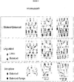
- occlusal scheme select options can be provided by the software as shown in the computer screen shot of FIG. 9 .
- the occlusal schemes can be classified as: a) bilateral balanced, b) lingualized, or c) linear, and the practitioner can select from one of these options.
- the bilateral balanced option is designated as the default occlusal scheme for illustration purposes. If the practitioner wishes, he/she can accept this default option.
- a set of predetermined denture base materials preferably is loaded in the software program and appear as select options on the computer screen as shown in FIG. 10 .
- denture bases made from such materials as Lucitone 199® acrylic resin or Eclipse@ baseplate resin which is a wax-like polymerizable material, both available from Dentsply can be added as predetermined selections.
- the user can enter the desired denture base material by clicking on the mouse and selecting either Lucitone 199® acrylic resin or Eclipse® baseplate resin. The desired color of the baseplate also needs to be entered.
- the baseplate color can be entered by selecting a color from a wide variety of select color options provided by the program. As also shown in FIG. 10 , several color options intended to resemble healthy gum tissue can be provided including light pink; light reddish pink; and dark pink. Alternatively, the baseplate can be clear and transparent. Eclipse® baseplates are available in a clear version. Desired denture base materials and colors can be selected from the automatically programmed sets. In preferred cases, the program includes default select denture base materials and colors. For example, in FIG. 10 , Lucitone 199® acrylic resin in its original color is designated as the default selection.
- the output of the system based on the input of data and other information as described above, is a digital prescription for making a denture for the given patient.
- the customized digital prescription includes detailed information on facial dimensions of the patient, tooth length, width and geometry, requested composition of the artificial teeth, edentulous ridge condition and occlusal scheme, denture base materials, and color and shade of the artificial teeth.
- the digital prescription is HIPAA-compliant. One example of such a digital prescription is shown below.
- the resulting customized digital prescription can be sent by e-mail, facsimile, paper mail, or other means to a dental laboratory that will manufacture the denture.
- a copy of the digital prescription can be provided to the patient for his/her records.
- the dental laboratory can use conventional techniques to fabricate the denture as prescribed.
- FIG. 11 a schematic diagram showing the basic steps of generating a customized digital prescription and transmitting the prescription to a dental laboratory in accordance with this invention are shown.
- the methods of this invention provide the dental practitioner with a new tool for designing and making dentures.
- the dentist can use the system to generate customized digital prescriptions.
- the system can be used as a tutorial for patients and staff in the dental office.
- the system offers many benefits including a quick and accurate means for prescribing dentures and recording the prescriptions.
- the system helps the practitioner by providing a step-by-step guide to designing a customized denture for a given patient. The practitioner is led step-by-step through the procedure.
- the system provides reference points across the facial digital image(s) of the patient so that the dentist can more accurately identify facial contours. Based on this information, the system automatically provides facial and tooth measurements and provides suggestions for tooth shade and denture base shade. Furthermore, the system prompts the practitioner by asking key questions such as: What is the edentulous ridge condition of patient? What is the occlusal scheme? What is the desired tooth arrangement? This helps the practitioner design a close fitting and comfortable denture. The resulting denture helps enhance the appearance of the patient and is fully functional. The system also helps facilitate two-way communication between the practitioner and patient. Rather than the practitioner deciding on the make and style of the denture and dictating this to the patient one-way, the patient is invited to participate in the process.
- the patient is asked for input on the desired tooth shade and denture base shade along with other decision points.
- the system is more interactive - the practitioner and patient are more engaged in the process. Each person feels that he/she has more input and control over the design and fabrication of the denture.
Landscapes
- Health & Medical Sciences (AREA)
- Oral & Maxillofacial Surgery (AREA)
- Dentistry (AREA)
- Epidemiology (AREA)
- Life Sciences & Earth Sciences (AREA)
- Animal Behavior & Ethology (AREA)
- General Health & Medical Sciences (AREA)
- Public Health (AREA)
- Veterinary Medicine (AREA)
- Dental Tools And Instruments Or Auxiliary Dental Instruments (AREA)
- Apparatus For Radiation Diagnosis (AREA)
Claims (15)
- Verfahren zur Herstellung von kundenspezifisch angepassten Zahnprothese-Rezepten, das die Schritte beinhaltet:a) Aufnehmen mindestens einer digitalen Photographie vom Gesicht eines Patienten, wobei eine Referenzplakette (24) auf der Stirn des Patienten platziert wurde und eine Mundplatte (26) im Mund des Patienten positioniert wurde, und Übertragen der Photographie in ein Computersoftwareprogramm, wobei das Programm Gesichtskonturen des Patienten basierend auf den relativen Abmessungen der Plakette (24) in der Photographie identifiziert und misst;b) Eingeben von gewünschten Materialien und Struktur zur Herstellung der Zahnprothese, in Konsultation mit dem Patienten, einschließlich eines gewünschten Zahnfarbtonschlüssels und eines Zahnfarbtons, wobei der Zahnfarbton aus dem eingegebenen Zahnfarbtonschlüssel ausgewählt wird, und zwar unter Verwendung des Softwareprogramms, so dass das Programm, basierend auf den eingegebenen Materialien und Struktur, automatisch ein Zahnprothese-Rezept erzeugt; undc) Übertragen des Rezeptes an ein Dentallabor zur Herstellung der Zahnprothese.
- Verfahren nach Anspruch 1, bei dem eine einzige Photographie vom Gesicht des Patienten aufgenommen wird, wobei die Photographie eine Frontalansicht ist.
- Verfahren nach Anspruch 1, wobei der Zahnfarbtonschlüssel herausnehmbare Farbtonplättchen beinhaltet.
- Verfahren nach Anspruch 1, wobei die Gesichtskonturen des Patienten verwendet werden, um die Länge, Breite und Form der bei der Zahnprothese verwendeten künstlichen Zähne zu bestimmen.
- Verfahren nach Anspruch 1, wobei das Eingeben der gewünschten Materialien für die Zahnprothese ein Eingeben von Zahngussformen für die bei der Zahnprothese verwendeten künstlichen Zähne beinhaltet, wobei vorzugsweise Frontzahn-Gussformen eingegeben werden, oder wobei Seitenzahn-Gussformen eingegeben werden.
- Verfahren nach Anspruch 1, wobei das Eingeben der gewünschten Struktur der Zahnprothese ein Eingeben einer Struktur eines unbezahnten Kieferkamms beinhaltet, wobei vorzugsweise die eingegebene Struktur des unbezahnten Kieferkamms auf der Zahngesundheit des Patienten basiert.
- Verfahren nach Anspruch 1, wobei das Eingeben der gewünschten Struktur der Zahnprothese ein Eingeben eines Okklusalschemas des Pateinten beinhaltet, wobei vorzugsweise das eingegebene Okklusalschema auf der Zahngesundheit des Patienten basiert.
- Verfahren nach Anspruch 1, wobei das Eingeben der gewünschten Materialien zur Herstellung der Zahnprothese ein Eingeben eines Basisplattenmaterials der Zahnprothese beinhaltet, wobei vorzugsweise das Basisplattenmaterial der Zahnprothese eine Farbe und einen Farbton aufweist, die zur Farbe und Farbton des Zahnfleisches des Patienten passt, oder wobei das Basisplattenmaterial der Zahnprothese im Wesentlichen transparent ist, oder wobei das Basisplattenmaterial der Zahnprothese aus einem Acrylpolymer hergestellt ist, oder wobei das Basisplattenmaterial der Zahnprothese aus einem wachsartigen polymerisierbaren Material hergestellt ist.
- Verfahren nach Anspruch 1, wobei das Rezept an das Dentallabor per E-Mail, Briefpost oder Fax übertragen wird, wobei das Rezept vorzugsweise auch dem Patienten zur Verfügung gestellt wird.
- Verfahren zur Herstellung von kundenspezifisch angepassten Zahnprothese-Rezepten, das die Schritte beinhaltet:a) Aufnehmen mindestens einer digitalen Photographie vom Gesicht eines Patienten, wobei eine Referenzplakette (24) auf der Stirn des Patienten platziert wurde und eine Mundplatte (26) im Mund des Patienten positioniert wurde, und Übertragen der Photographie in ein Computersoftwareprogramm, wobei das Programm Gesichtskonturen des Patienten basierend auf den relativen Abmessungen der Plakette (24) in der Photographie identifiziert und misst;b) Auswählen von gewünschten Materialien und Struktur zur Herstellung der Zahnprothese, in Konsultation mit dem Patienten, einschließlich eines gewünschten Zahnfarbtonschlüssels und eines Zahnfarbtons, wobei der Zahnfarbton aus dem ausgewählten Zahnfarbtonschlüssel ausgewählt wird, und zwar aus einem Satz von vorbestimmten Materialien und Strukturen, die durch das Softwareprogramms bereitgestellt werden, so dass das Programm, basierend auf den ausgewählten Materialien und Struktur, automatisch ein Zahnprothese-Rezept erzeugt; undc) Übertragen des Rezeptes an ein Dentallabor zur Herstellung der Zahnprothese.
- Verfahren nach Anspruch 10, wobei der Satz von vorbestimmten Strukturen und Materialien mindestens zwei Optionen zur Auswahl des Zahnfarbtonschlüssels beinhaltet, wobei vorzugsweise eine der Farbtonschlüsseloptionen als Vorgabeoption festgelegt ist.
- Verfahren nach Anspruch 10, wobei der Satz von vorbestimmten Strukturen und Materialien mindestens zwei Optionen zum Auswählen einer Zahngussform für bei der Zahnprothese verwendete künstliche Zähne beinhaltet, wobei die Zahngussformoptionen vorzugsweise für Frontzähne sind, oder wobei die Zahngussformoptionen für Seitenzähne sind, oder wobei eine der Gussformoptionen als Vorgabeoption festgelegt ist.
- Verfahren nach Anspruch 10, wobei der Satz von vorbestimmten Strukturen und Materialien mindestens zwei Optionen zum Auswählen einer Struktur des unbezahnten Kieferkamms des Patienten beinhaltet.
- Verfahren nach Anspruch 10, wobei der Satz von vorbestimmten Strukturen und Materialien mindestens zwei Optionen zum Auswählen eines Okklusalschemas des Pateinten beinhaltet, wobei vorzugsweise eine der Okklusalschemaoptionen als Vorgabeoption festgelegt ist.
- Verfahren nach Anspruch 10, wobei der Satz von vorbestimmten Strukturen und Materialien mindestens zwei Optionen zum Auswählen eines Basismaterials einer Zahnprothese und mindestens zwei Optionen zum Auswählen einer Basisfarbe einer Zahnprothese beinhaltet, wobei vorzugsweise eine der Basismaterialoptionen der Zahnprothese als Vorgabeoption festgelegt ist und eine der Basisfarben der Zahnprothese als Vorgabeoption festgelegt ist, oder wobei das Rezept an das Dentallabor per E-Mail, Briefpost oder Fax übertragen wird, wobei das Rezept vorzugsweise auch dem Patienten zur Verfügung gestellt wird.
Applications Claiming Priority (3)
| Application Number | Priority Date | Filing Date | Title |
|---|---|---|---|
| US13062208P | 2008-06-02 | 2008-06-02 | |
| US20579709P | 2009-01-23 | 2009-01-23 | |
| PCT/US2009/003351 WO2010008435A1 (en) | 2008-06-02 | 2009-06-02 | Methods for designing a customized dental prosthesis using digital images of a patient |
Publications (2)
| Publication Number | Publication Date |
|---|---|
| EP2282697A1 EP2282697A1 (de) | 2011-02-16 |
| EP2282697B1 true EP2282697B1 (de) | 2016-12-14 |
Family
ID=41128063
Family Applications (1)
| Application Number | Title | Priority Date | Filing Date |
|---|---|---|---|
| EP09788791.3A Active EP2282697B1 (de) | 2008-06-02 | 2009-06-02 | Verfahren zur konzeption einer massgeschneiderten zahnprothese mithilfe digitaler patientenbilder |
Country Status (5)
| Country | Link |
|---|---|
| US (1) | US8386061B2 (de) |
| EP (1) | EP2282697B1 (de) |
| JP (1) | JP5586590B2 (de) |
| CA (1) | CA2725818C (de) |
| WO (1) | WO2010008435A1 (de) |
Families Citing this family (27)
| Publication number | Priority date | Publication date | Assignee | Title |
|---|---|---|---|---|
| DE102009056752C5 (de) * | 2009-12-04 | 2024-04-04 | Kulzer Gmbh | Herstellung individueller dentaler Prothesen via CAD/CAM und Rapid Manufacturing/Rapid Prototyping aus Daten der digitalen Abdrucknahme |
| USRE49008E1 (en) | 2010-02-19 | 2022-04-05 | 3Shape A/S | Method of composing and designing a set of teeth |
| JP2013531531A (ja) | 2010-06-29 | 2013-08-08 | 3シェイプ アー/エス | 2d画像配置 |
| US9402698B2 (en) * | 2010-11-03 | 2016-08-02 | Global Dental Service LLC | Systems and processes for forming anatomical features in dentures |
| US10092373B2 (en) * | 2011-05-15 | 2018-10-09 | Orametrix, Inc. | Orthodontic treatment planning using lip tracer |
| US20130166312A1 (en) * | 2011-12-23 | 2013-06-27 | Frank LAUCIELLO | System and method for tooth selection and order generation |
| JP6262018B2 (ja) * | 2013-03-22 | 2018-01-17 | 株式会社ギコウ | 有床義歯の製造方法 |
| CN103226658B (zh) * | 2013-04-16 | 2016-05-04 | 江苏物联网研究发展中心 | 牙齿诊断修复辅助系统 |
| WO2015031367A2 (en) | 2013-08-26 | 2015-03-05 | James R. Glidewell Dental Ceramics, Inc. | Computer-implemented dental restoration design |
| ES2518665B1 (es) | 2013-11-29 | 2015-10-13 | Dentalliance Network, S.L. | Método para la planificación de tratamiento dental |
| US10010387B2 (en) | 2014-02-07 | 2018-07-03 | 3Shape A/S | Detecting tooth shade |
| CN106255473B (zh) | 2014-02-21 | 2020-08-07 | 特里斯佩拉牙科公司 | 增强现实牙科设计方法及系统 |
| US10251733B2 (en) | 2014-03-03 | 2019-04-09 | Global Dental Science Llc | System and method for manufacturing layered dentures |
| DE102014215103C5 (de) * | 2014-07-31 | 2022-12-29 | Sirona Dental Systems Gmbh | Verfahren zur virtuellen Nachbearbeitung eines Gingivamodells |
| JP5807131B1 (ja) | 2015-01-22 | 2015-11-10 | 株式会社松風 | 欠損歯牙形態決定方法 |
| US10327867B2 (en) | 2015-02-25 | 2019-06-25 | James R. Glidewell Dental Ceramics, Inc. | Arch form placement for dental restoration design |
| US9877814B2 (en) * | 2015-05-01 | 2018-01-30 | Sirona Dental Systems Gmbh | Methods, apparatuses, computer programs, and systems for creating a custom dental prosthesis using a CAD/CAM system |
| US20170000591A1 (en) * | 2015-06-30 | 2017-01-05 | Tcm | Method And Device For Manufacturing And Controlling The Conformity Of A Dental Prosthesis From Parameters Obtained With A Shade Selecting Device |
| US11284969B2 (en) * | 2016-03-16 | 2022-03-29 | Easyrx, Llc. | System and method for ordering and manufacturing customized dental appliances and the tracking of orthodontic products |
| EP3372193B1 (de) * | 2017-03-08 | 2021-04-21 | Ivoclar Vivadent AG | Verfahren zur festlegung einer materialfarbe einer dentalrestauration |
| DE102017217558A1 (de) * | 2017-10-02 | 2019-04-04 | Sirona Dental Systems Gmbh | Verfahren zur Herstellung einer geführten Aufbissschiene und eine geführte Aufbissschiene |
| DK3632369T3 (da) * | 2018-10-02 | 2022-03-28 | Sirona Dental Systems Gmbh | Fremgangsmåde til inkorporering af fotografiske ansigtsbilleder og/eller -film af en person i planlægningen af odontologiske og/eller kosmetiske tandbehandlinger og/eller forberedelse af restaureringer for samme person |
| KR20200075623A (ko) * | 2018-12-18 | 2020-06-26 | (주)제노레이 | 2차원 의료 영상 및 3차원 의료 영상의 정합을 이용한 치과 치료 계획 장치 및 방법 |
| CN110974461B (zh) * | 2019-12-14 | 2021-05-11 | 深圳市爱科赢自动化技术有限公司 | 一种整体式全口义齿数字化制作系统及方法 |
| US20220401192A1 (en) * | 2021-06-22 | 2022-12-22 | Reset Technology Corporation | Systems and methods for providing oral devices using at-home dental impression kits |
| KR102573908B1 (ko) * | 2021-08-13 | 2023-09-05 | 오스템임플란트 주식회사 | 안모 형태 분류 방법 및 이를 위한 의치 디자인 장치 |
| KR102567348B1 (ko) * | 2021-08-25 | 2023-08-17 | 오스템임플란트 주식회사 | 보철물을 디스플레이하는 방법, 디바이스 및 그 기록매체 |
Family Cites Families (82)
| Publication number | Priority date | Publication date | Assignee | Title |
|---|---|---|---|---|
| US4583947A (en) * | 1983-03-17 | 1986-04-22 | Hazco Development Inc. | Custom dentures and method of making same |
| EP0207089A1 (de) | 1984-11-28 | 1987-01-07 | DI MATTIA, Massimo | Spektrophotometer zur genauen bestimmung der farbe einer zahnplatte und von zahnfüllungen |
| US4681543A (en) * | 1986-02-14 | 1987-07-21 | Dentsply Research & Development Corp. | Rapid denture technique |
| FR2637368B1 (fr) | 1988-09-09 | 1990-12-07 | Bertin & Cie | Procede de determination de la couleur d'un objet, en particulier d'une prothese dentaire |
| US5055039A (en) * | 1988-10-06 | 1991-10-08 | Great Lakes Orthodontics, Ltd. | Orthodontic positioner and methods of making and using same |
| US5011405A (en) | 1989-01-24 | 1991-04-30 | Dolphin Imaging Systems | Method for determining orthodontic bracket placement |
| US5027281A (en) * | 1989-06-09 | 1991-06-25 | Regents Of The University Of Minnesota | Method and apparatus for scanning and recording of coordinates describing three dimensional objects of complex and unique geometry |
| GB8918605D0 (en) | 1989-08-15 | 1989-09-27 | Mckeown Samuel T J | Shade distinguishing device |
| US5001405A (en) * | 1989-09-27 | 1991-03-19 | Seagate Technology, Inc. | Position detection for a brushless DC motor |
| US5139419A (en) * | 1990-01-19 | 1992-08-18 | Ormco Corporation | Method of forming an orthodontic brace |
| US5395238A (en) * | 1990-01-19 | 1995-03-07 | Ormco Corporation | Method of forming orthodontic brace |
| GB9003172D0 (en) | 1990-02-13 | 1990-04-11 | Benn Computer Consultants | Analysing screen-displayed images |
| US5691905A (en) * | 1990-06-11 | 1997-11-25 | Dentsply Research & Development Corp. | Prosthetic teeth and mold making and polishing therefor |
| US5452219A (en) * | 1990-06-11 | 1995-09-19 | Dentsply Research & Development Corp. | Method of making a tooth mold |
| ATE145125T1 (de) | 1991-03-06 | 1996-11-15 | Ormco Corp | Orthodontische stütze und verfahren zu ihrer herstellung |
| US5273429A (en) * | 1992-04-03 | 1993-12-28 | Foster-Miller, Inc. | Method and apparatus for modeling a dental prosthesis |
| WO1994010935A1 (en) * | 1992-11-09 | 1994-05-26 | Ormco Corporation | Custom orthodontic appliance forming method and apparatus |
| US6218994B1 (en) * | 1993-10-04 | 2001-04-17 | The United States Of America As Represented By The Secretary Of The Navy | Small antennas for communication over sea ice |
| DE4341367C1 (de) * | 1993-12-04 | 1995-06-14 | Harald Dr Med Dr Med Eufinger | Verfahren zur Herstellung von Endoprothesen |
| SE502035C2 (sv) | 1993-12-06 | 1995-07-24 | Nobelpharma Ab | Metod och och anordning för framtagning av information för framställning av artifiella stödorgan eller ersättningsdelar till människokroppen |
| US5766006A (en) * | 1995-06-26 | 1998-06-16 | Murljacic; Maryann Lehmann | Tooth shade analyzer system and methods |
| JP3727660B2 (ja) | 1995-07-21 | 2005-12-14 | カデント・リミテッド | 3次元の歯の像を入手するための方法 |
| US5718585A (en) * | 1995-09-15 | 1998-02-17 | Dentsply Research & Development Corp. | Prosthetic teeth and mold making therefor |
| JPH1075963A (ja) | 1996-09-06 | 1998-03-24 | Nikon Corp | 歯科補綴物モデルの設計方法およびこの方法を実行するプログラムを記録した媒体 |
| US6007332A (en) * | 1996-09-26 | 1999-12-28 | O'brien; William J. | Tooth color matching system |
| AUPO280996A0 (en) * | 1996-10-04 | 1996-10-31 | Dentech Investments Pty Ltd | Creation and utilization of 3D teeth models |
| US6217334B1 (en) | 1997-01-28 | 2001-04-17 | Iris Development Corporation | Dental scanning method and apparatus |
| US5879158A (en) * | 1997-05-20 | 1999-03-09 | Doyle; Walter A. | Orthodontic bracketing system and method therefor |
| US6309215B1 (en) * | 1997-06-20 | 2001-10-30 | Align Technology Inc. | Attachment devices and method for a dental applicance |
| US5975893A (en) * | 1997-06-20 | 1999-11-02 | Align Technology, Inc. | Method and system for incrementally moving teeth |
| US6152731A (en) * | 1997-09-22 | 2000-11-28 | 3M Innovative Properties Company | Methods for use in dental articulation |
| US6200278B1 (en) * | 1997-10-16 | 2001-03-13 | Arnett Facial Reconstruction Courses, Inc. | Gender specific soft tissue cephalometric analysis for diagnosis and cephalometric treatment planning of facial imbalance |
| US5882192A (en) * | 1997-10-30 | 1999-03-16 | Ortho-Tain, Inc. | Computerized orthodontic diagnosis and appliance dispenser |
| IL122807A0 (en) | 1997-12-30 | 1998-08-16 | Cadent Ltd | Virtual orthodontic treatment |
| JP2895047B1 (ja) * | 1998-03-18 | 1999-05-24 | 株式会社シケン | 歯科用補綴物の人工歯・歯肉見本 |
| US6089868A (en) * | 1998-05-14 | 2000-07-18 | 3M Innovative Properties Company | Selection of orthodontic appliances |
| US6573984B2 (en) * | 1998-06-30 | 2003-06-03 | Lj Laboratories Llc | Apparatus and method for measuring optical characteristics of teeth |
| US6525819B1 (en) | 1998-09-02 | 2003-02-25 | Pocketspec Technologies Inc. | Colorimeter for dental applications |
| US6227850B1 (en) * | 1999-05-13 | 2001-05-08 | Align Technology, Inc. | Teeth viewing system |
| JP4230113B2 (ja) * | 1998-11-03 | 2009-02-25 | シェード アナライジング テクノロジーズ インコーポレイテッド | 双方向歯科治療ネットワーク |
| EP2133820A3 (de) | 1998-11-03 | 2010-02-10 | Shade Analyzing Technologies, Inc. | System und Verfahren zur analyse der farblichen Nuancen von Zähnen |
| JP3040997B1 (ja) * | 1999-03-29 | 2000-05-15 | 佳知 高石 | 上顎歯寸法決定装置 |
| US6318994B1 (en) | 1999-05-13 | 2001-11-20 | Align Technology, Inc | Tooth path treatment plan |
| JP3079155B1 (ja) * | 1999-07-02 | 2000-08-21 | 有限会社 保母須弥也研究所 | 歯科用シェ−ド・システム |
| US6632089B2 (en) | 1999-11-30 | 2003-10-14 | Orametrix, Inc. | Orthodontic treatment planning with user-specified simulation of tooth movement |
| US6688885B1 (en) * | 1999-11-30 | 2004-02-10 | Orametrix, Inc | Method and apparatus for treating an orthodontic patient |
| US6464496B1 (en) * | 1999-11-30 | 2002-10-15 | Orametrix, Inc. | Method and apparatus for determining and monitoring orthodontic treatment |
| US6250918B1 (en) * | 1999-11-30 | 2001-06-26 | Orametrix, Inc. | Method and apparatus for simulating tooth movement for an orthodontic patient |
| US6648640B2 (en) * | 1999-11-30 | 2003-11-18 | Ora Metrix, Inc. | Interactive orthodontic care system based on intra-oral scanning of teeth |
| AU2607301A (en) | 1999-12-29 | 2001-07-09 | Ormco Corporation | Custom orthodontic appliance forming method and apparatus |
| IL150597A0 (en) | 2000-01-14 | 2003-02-12 | Britesmile Inc | Tooth whitening and image enhancement center method |
| JP3732474B2 (ja) * | 2000-06-28 | 2006-01-05 | 喜美男 儀間 | 義歯の固定構造とその製作方法 |
| CA2342709A1 (en) * | 2001-03-23 | 2002-09-23 | Dentalmatic Technologies Inc. | Methods for dental restoration |
| US7156655B2 (en) | 2001-04-13 | 2007-01-02 | Orametrix, Inc. | Method and system for comprehensive evaluation of orthodontic treatment using unified workstation |
| US7717708B2 (en) * | 2001-04-13 | 2010-05-18 | Orametrix, Inc. | Method and system for integrated orthodontic treatment planning using unified workstation |
| US7215803B2 (en) * | 2001-04-29 | 2007-05-08 | Geodigm Corporation | Method and apparatus for interactive remote viewing and collaboration of dental images |
| JP2003135488A (ja) * | 2001-11-07 | 2003-05-13 | Shiyuukai | 義 歯 |
| JP3731525B2 (ja) * | 2001-11-09 | 2006-01-05 | ソニー株式会社 | 情報処理装置および情報処理方法、情報処理システム、並びにプログラム |
| JP2004030158A (ja) * | 2002-06-25 | 2004-01-29 | Dent Craft:Kk | 歯科用補綴物の材料を特定するための方法、装置及びプログラム |
| US20040152036A1 (en) * | 2002-09-10 | 2004-08-05 | Amir Abolfathi | Architecture for treating teeth |
| US20040248066A1 (en) * | 2003-06-03 | 2004-12-09 | Recigno David T. | Dental appliance on-line ordering including display of end product image and mold three-dimensional scanning for digital transmission |
| US7118374B2 (en) * | 2003-06-09 | 2006-10-10 | Ivoclar Vivadent Ag | Enhanced tooth shade guide |
| US7064830B2 (en) | 2003-06-12 | 2006-06-20 | Eastman Kodak Company | Dental color imaging system |
| US7474932B2 (en) * | 2003-10-23 | 2009-01-06 | Technest Holdings, Inc. | Dental computer-aided design (CAD) methods and systems |
| US20080270175A1 (en) * | 2003-12-31 | 2008-10-30 | Klinger Advanced Aesthetics, Inc. | Systems and methods using a dynamic expert system to provide patients with aesthetic improvement procedures |
| DE102004002724B4 (de) * | 2004-01-19 | 2006-06-14 | Ivoclar Vivadent Ag | Brennofen sowie Verfahren für den Betrieb eines Brennofens für den Dentalbereich |
| JP4616318B2 (ja) * | 2004-01-23 | 2011-01-19 | オリンパス株式会社 | カメラ |
| CN101699850A (zh) * | 2004-01-23 | 2010-04-28 | 奥林巴斯株式会社 | 图像处理系统以及照相机 |
| US7128572B2 (en) * | 2004-02-12 | 2006-10-31 | Ivoclar Vivadent Ag | Method and apparatus for selecting denture teeth |
| US7128573B2 (en) * | 2004-02-19 | 2006-10-31 | Pentron Clinical Technologies, Llc | Device for determining shades of dental restorations |
| US7333874B2 (en) | 2004-02-24 | 2008-02-19 | Cadent Ltd. | Method and system for designing and producing dental prostheses and appliances |
| US7840042B2 (en) | 2006-01-20 | 2010-11-23 | 3M Innovative Properties Company | Superposition for visualization of three-dimensional data acquisition |
| WO2007103303A2 (en) | 2006-03-06 | 2007-09-13 | Klinger Advanced Aesthetics Inc. | Systems and methods using a dynamic expert system to provide patients with aesthetic improvement procedures |
| US8254637B2 (en) * | 2006-07-27 | 2012-08-28 | Resmed Limited | Mask fitting system and method |
| JP5489718B2 (ja) | 2006-09-28 | 2014-05-14 | デンツプライ インターナショナル インコーポレーテッド | 表面処理組成物を用いた歯科器具を製造する方法 |
| ITMO20060417A1 (it) | 2006-12-21 | 2008-06-22 | Marcello Marchesi | Metodo per la progettazione e l'esecuzione di trattamenti odontoiatrici |
| DE102006060682A1 (de) * | 2006-12-21 | 2008-06-26 | Manfred Wiedmann | Verfahren zur Rekonstruktion von Zähnen |
| US20080195418A1 (en) * | 2007-02-13 | 2008-08-14 | Parker Stephen H | Method for generating a prescription for orthodontic appliances |
| JP2011512897A (ja) * | 2008-02-22 | 2011-04-28 | グラクソスミスクライン・リミテッド・ライアビリティ・カンパニー | 義歯を電子的にモデリングし製造するための方法および装置 |
| AU2009217329A1 (en) * | 2008-02-22 | 2009-08-27 | Glaxosmithkline Llc | Systems and methods for providing customized dentures |
| CA2716329A1 (en) * | 2008-02-22 | 2009-08-27 | Glaxosmithkline Llc | Methods and apparatus for producing dental stones and base plates used in making dentures |
| KR20100138952A (ko) * | 2008-02-22 | 2010-12-31 | 글락소스미스클라인 엘엘씨 | 맞춤형 의치를 제조하는 장치 및 방법 |
-
2009
- 2009-06-02 WO PCT/US2009/003351 patent/WO2010008435A1/en active Application Filing
- 2009-06-02 US US12/455,443 patent/US8386061B2/en active Active
- 2009-06-02 CA CA2725818A patent/CA2725818C/en active Active
- 2009-06-02 JP JP2011512467A patent/JP5586590B2/ja active Active
- 2009-06-02 EP EP09788791.3A patent/EP2282697B1/de active Active
Non-Patent Citations (1)
| Title |
|---|
| None * |
Also Published As
| Publication number | Publication date |
|---|---|
| CA2725818A1 (en) | 2010-01-21 |
| EP2282697A1 (de) | 2011-02-16 |
| US8386061B2 (en) | 2013-02-26 |
| US20100076581A1 (en) | 2010-03-25 |
| JP2011521767A (ja) | 2011-07-28 |
| WO2010008435A1 (en) | 2010-01-21 |
| CA2725818C (en) | 2013-12-31 |
| JP5586590B2 (ja) | 2014-09-10 |
Similar Documents
| Publication | Publication Date | Title |
|---|---|---|
| EP2282697B1 (de) | Verfahren zur konzeption einer massgeschneiderten zahnprothese mithilfe digitaler patientenbilder | |
| US9411910B2 (en) | Dental analysis method and system | |
| Coachman et al. | Smile design: From digital treatment planning to clinical reality | |
| US8352060B2 (en) | Computer-aided fabrication of a removable dental prosthesis | |
| CA2619273C (en) | Dental analysis method and system | |
| US9861457B2 (en) | System and method for effective planning, visualization, and optimization of dental restorations | |
| JP2020508734A (ja) | 修復物の構築方法 | |
| US8998615B2 (en) | Method and apparatus for preparing denture | |
| AU2019289452B2 (en) | Method for constructing a dental component | |
| CA2761914A1 (en) | Method and apparatus for preparing denture | |
| US20230000592A1 (en) | Method and apparatus for dental crown restorations using prefabricated sleeve-crown pairs | |
| Besford et al. | Aesthetic possibilities in removable prosthodontics. Part 3: Photometric tooth selection, tooth setting, try-in, fitting, reviewing and trouble-shooting | |
| Kovacs et al. | Aesthetic smile evaluation-a non-invasive solution | |
| Al-Hassiny | Fundamentals of Computer-Aided Design (CAD) in Dental Healthcare: From Basics to Beyond | |
| Birnbaum et al. | Digital impression devices and CAD/CAM systems | |
| Park et al. | Optical impression in restorative dentistry | |
| Hack et al. | Digital impressions | |
| Hooda et al. | Digital Smile Design | |
| Mullick et al. | Smile Design Software: A Virtual Avenue To Treatment Planning | |
| Pereverzyev | Digital Dentistry: A Review of Modern Innovations for CAD/CAM Generated Restoration | |
| Weston | DIGITALLY GUIDED: Porcelain Veneer Smile Design. | |
| Shigli et al. | It’s All About the PRESCRIPTION |
Legal Events
| Date | Code | Title | Description |
|---|---|---|---|
| PUAI | Public reference made under article 153(3) epc to a published international application that has entered the european phase |
Free format text: ORIGINAL CODE: 0009012 |
|
| 17P | Request for examination filed |
Effective date: 20101126 |
|
| AK | Designated contracting states |
Kind code of ref document: A1 Designated state(s): AT BE BG CH CY CZ DE DK EE ES FI FR GB GR HR HU IE IS IT LI LT LU LV MC MK MT NL NO PL PT RO SE SI SK TR |
|
| AX | Request for extension of the european patent |
Extension state: AL BA RS |
|
| DAX | Request for extension of the european patent (deleted) | ||
| 17Q | First examination report despatched |
Effective date: 20130422 |
|
| GRAP | Despatch of communication of intention to grant a patent |
Free format text: ORIGINAL CODE: EPIDOSNIGR1 |
|
| INTG | Intention to grant announced |
Effective date: 20160804 |
|
| GRAS | Grant fee paid |
Free format text: ORIGINAL CODE: EPIDOSNIGR3 |
|
| GRAA | (expected) grant |
Free format text: ORIGINAL CODE: 0009210 |
|
| AK | Designated contracting states |
Kind code of ref document: B1 Designated state(s): AT BE BG CH CY CZ DE DK EE ES FI FR GB GR HR HU IE IS IT LI LT LU LV MC MK MT NL NO PL PT RO SE SI SK TR |
|
| REG | Reference to a national code |
Ref country code: GB Ref legal event code: FG4D |
|
| REG | Reference to a national code |
Ref country code: CH Ref legal event code: EP Ref country code: CH Ref legal event code: NV Representative=s name: E. BLUM AND CO. AG PATENT- UND MARKENANWAELTE , CH |
|
| REG | Reference to a national code |
Ref country code: IE Ref legal event code: FG4D |
|
| REG | Reference to a national code |
Ref country code: AT Ref legal event code: REF Ref document number: 852867 Country of ref document: AT Kind code of ref document: T Effective date: 20170115 |
|
| REG | Reference to a national code |
Ref country code: DE Ref legal event code: R096 Ref document number: 602009043106 Country of ref document: DE |
|
| REG | Reference to a national code |
Ref country code: NL Ref legal event code: FP |
|
| PG25 | Lapsed in a contracting state [announced via postgrant information from national office to epo] |
Ref country code: LV Free format text: LAPSE BECAUSE OF FAILURE TO SUBMIT A TRANSLATION OF THE DESCRIPTION OR TO PAY THE FEE WITHIN THE PRESCRIBED TIME-LIMIT Effective date: 20161214 |
|
| REG | Reference to a national code |
Ref country code: SE Ref legal event code: TRGR |
|
| REG | Reference to a national code |
Ref country code: LT Ref legal event code: MG4D |
|
| PG25 | Lapsed in a contracting state [announced via postgrant information from national office to epo] |
Ref country code: NO Free format text: LAPSE BECAUSE OF FAILURE TO SUBMIT A TRANSLATION OF THE DESCRIPTION OR TO PAY THE FEE WITHIN THE PRESCRIBED TIME-LIMIT Effective date: 20170314 Ref country code: LT Free format text: LAPSE BECAUSE OF FAILURE TO SUBMIT A TRANSLATION OF THE DESCRIPTION OR TO PAY THE FEE WITHIN THE PRESCRIBED TIME-LIMIT Effective date: 20161214 Ref country code: GR Free format text: LAPSE BECAUSE OF FAILURE TO SUBMIT A TRANSLATION OF THE DESCRIPTION OR TO PAY THE FEE WITHIN THE PRESCRIBED TIME-LIMIT Effective date: 20170315 |
|
| REG | Reference to a national code |
Ref country code: FR Ref legal event code: PLFP Year of fee payment: 9 |
|
| REG | Reference to a national code |
Ref country code: AT Ref legal event code: MK05 Ref document number: 852867 Country of ref document: AT Kind code of ref document: T Effective date: 20161214 |
|
| PG25 | Lapsed in a contracting state [announced via postgrant information from national office to epo] |
Ref country code: HR Free format text: LAPSE BECAUSE OF FAILURE TO SUBMIT A TRANSLATION OF THE DESCRIPTION OR TO PAY THE FEE WITHIN THE PRESCRIBED TIME-LIMIT Effective date: 20161214 Ref country code: FI Free format text: LAPSE BECAUSE OF FAILURE TO SUBMIT A TRANSLATION OF THE DESCRIPTION OR TO PAY THE FEE WITHIN THE PRESCRIBED TIME-LIMIT Effective date: 20161214 |
|
| PG25 | Lapsed in a contracting state [announced via postgrant information from national office to epo] |
Ref country code: CZ Free format text: LAPSE BECAUSE OF FAILURE TO SUBMIT A TRANSLATION OF THE DESCRIPTION OR TO PAY THE FEE WITHIN THE PRESCRIBED TIME-LIMIT Effective date: 20161214 Ref country code: SK Free format text: LAPSE BECAUSE OF FAILURE TO SUBMIT A TRANSLATION OF THE DESCRIPTION OR TO PAY THE FEE WITHIN THE PRESCRIBED TIME-LIMIT Effective date: 20161214 Ref country code: IS Free format text: LAPSE BECAUSE OF FAILURE TO SUBMIT A TRANSLATION OF THE DESCRIPTION OR TO PAY THE FEE WITHIN THE PRESCRIBED TIME-LIMIT Effective date: 20170414 Ref country code: EE Free format text: LAPSE BECAUSE OF FAILURE TO SUBMIT A TRANSLATION OF THE DESCRIPTION OR TO PAY THE FEE WITHIN THE PRESCRIBED TIME-LIMIT Effective date: 20161214 Ref country code: RO Free format text: LAPSE BECAUSE OF FAILURE TO SUBMIT A TRANSLATION OF THE DESCRIPTION OR TO PAY THE FEE WITHIN THE PRESCRIBED TIME-LIMIT Effective date: 20161214 |
|
| PG25 | Lapsed in a contracting state [announced via postgrant information from national office to epo] |
Ref country code: BE Free format text: LAPSE BECAUSE OF FAILURE TO SUBMIT A TRANSLATION OF THE DESCRIPTION OR TO PAY THE FEE WITHIN THE PRESCRIBED TIME-LIMIT Effective date: 20161214 Ref country code: PT Free format text: LAPSE BECAUSE OF FAILURE TO SUBMIT A TRANSLATION OF THE DESCRIPTION OR TO PAY THE FEE WITHIN THE PRESCRIBED TIME-LIMIT Effective date: 20170414 Ref country code: ES Free format text: LAPSE BECAUSE OF FAILURE TO SUBMIT A TRANSLATION OF THE DESCRIPTION OR TO PAY THE FEE WITHIN THE PRESCRIBED TIME-LIMIT Effective date: 20161214 Ref country code: BG Free format text: LAPSE BECAUSE OF FAILURE TO SUBMIT A TRANSLATION OF THE DESCRIPTION OR TO PAY THE FEE WITHIN THE PRESCRIBED TIME-LIMIT Effective date: 20170314 Ref country code: AT Free format text: LAPSE BECAUSE OF FAILURE TO SUBMIT A TRANSLATION OF THE DESCRIPTION OR TO PAY THE FEE WITHIN THE PRESCRIBED TIME-LIMIT Effective date: 20161214 Ref country code: PL Free format text: LAPSE BECAUSE OF FAILURE TO SUBMIT A TRANSLATION OF THE DESCRIPTION OR TO PAY THE FEE WITHIN THE PRESCRIBED TIME-LIMIT Effective date: 20161214 |
|
| REG | Reference to a national code |
Ref country code: DE Ref legal event code: R097 Ref document number: 602009043106 Country of ref document: DE |
|
| PLBE | No opposition filed within time limit |
Free format text: ORIGINAL CODE: 0009261 |
|
| STAA | Information on the status of an ep patent application or granted ep patent |
Free format text: STATUS: NO OPPOSITION FILED WITHIN TIME LIMIT |
|
| 26N | No opposition filed |
Effective date: 20170915 |
|
| PG25 | Lapsed in a contracting state [announced via postgrant information from national office to epo] |
Ref country code: DK Free format text: LAPSE BECAUSE OF FAILURE TO SUBMIT A TRANSLATION OF THE DESCRIPTION OR TO PAY THE FEE WITHIN THE PRESCRIBED TIME-LIMIT Effective date: 20161214 |
|
| PG25 | Lapsed in a contracting state [announced via postgrant information from national office to epo] |
Ref country code: MC Free format text: LAPSE BECAUSE OF FAILURE TO SUBMIT A TRANSLATION OF THE DESCRIPTION OR TO PAY THE FEE WITHIN THE PRESCRIBED TIME-LIMIT Effective date: 20161214 |
|
| REG | Reference to a national code |
Ref country code: NL Ref legal event code: MM Effective date: 20170701 |
|
| PG25 | Lapsed in a contracting state [announced via postgrant information from national office to epo] |
Ref country code: SI Free format text: LAPSE BECAUSE OF FAILURE TO SUBMIT A TRANSLATION OF THE DESCRIPTION OR TO PAY THE FEE WITHIN THE PRESCRIBED TIME-LIMIT Effective date: 20161214 |
|
| REG | Reference to a national code |
Ref country code: IE Ref legal event code: MM4A |
|
| PG25 | Lapsed in a contracting state [announced via postgrant information from national office to epo] |
Ref country code: NL Free format text: LAPSE BECAUSE OF NON-PAYMENT OF DUE FEES Effective date: 20170701 |
|
| PG25 | Lapsed in a contracting state [announced via postgrant information from national office to epo] |
Ref country code: LU Free format text: LAPSE BECAUSE OF NON-PAYMENT OF DUE FEES Effective date: 20170602 Ref country code: IE Free format text: LAPSE BECAUSE OF NON-PAYMENT OF DUE FEES Effective date: 20170602 |
|
| REG | Reference to a national code |
Ref country code: FR Ref legal event code: PLFP Year of fee payment: 10 |
|
| PG25 | Lapsed in a contracting state [announced via postgrant information from national office to epo] |
Ref country code: MT Free format text: LAPSE BECAUSE OF NON-PAYMENT OF DUE FEES Effective date: 20170602 |
|
| PG25 | Lapsed in a contracting state [announced via postgrant information from national office to epo] |
Ref country code: HU Free format text: LAPSE BECAUSE OF FAILURE TO SUBMIT A TRANSLATION OF THE DESCRIPTION OR TO PAY THE FEE WITHIN THE PRESCRIBED TIME-LIMIT; INVALID AB INITIO Effective date: 20090602 |
|
| PG25 | Lapsed in a contracting state [announced via postgrant information from national office to epo] |
Ref country code: CY Free format text: LAPSE BECAUSE OF NON-PAYMENT OF DUE FEES Effective date: 20161214 |
|
| PG25 | Lapsed in a contracting state [announced via postgrant information from national office to epo] |
Ref country code: MK Free format text: LAPSE BECAUSE OF FAILURE TO SUBMIT A TRANSLATION OF THE DESCRIPTION OR TO PAY THE FEE WITHIN THE PRESCRIBED TIME-LIMIT Effective date: 20161214 |
|
| PG25 | Lapsed in a contracting state [announced via postgrant information from national office to epo] |
Ref country code: TR Free format text: LAPSE BECAUSE OF FAILURE TO SUBMIT A TRANSLATION OF THE DESCRIPTION OR TO PAY THE FEE WITHIN THE PRESCRIBED TIME-LIMIT Effective date: 20161214 |
|
| P01 | Opt-out of the competence of the unified patent court (upc) registered |
Effective date: 20230511 |
|
| PGFP | Annual fee paid to national office [announced via postgrant information from national office to epo] |
Ref country code: IT Payment date: 20230510 Year of fee payment: 15 Ref country code: FR Payment date: 20230510 Year of fee payment: 15 Ref country code: DE Payment date: 20230502 Year of fee payment: 15 |
|
| PGFP | Annual fee paid to national office [announced via postgrant information from national office to epo] |
Ref country code: SE Payment date: 20230510 Year of fee payment: 15 |
|
| PGFP | Annual fee paid to national office [announced via postgrant information from national office to epo] |
Ref country code: GB Payment date: 20230504 Year of fee payment: 15 Ref country code: CH Payment date: 20230702 Year of fee payment: 15 |