EP2282138A2 - Erhitzer und Haarpflegevorrichtung damit - Google Patents
Erhitzer und Haarpflegevorrichtung damit Download PDFInfo
- Publication number
- EP2282138A2 EP2282138A2 EP10166108A EP10166108A EP2282138A2 EP 2282138 A2 EP2282138 A2 EP 2282138A2 EP 10166108 A EP10166108 A EP 10166108A EP 10166108 A EP10166108 A EP 10166108A EP 2282138 A2 EP2282138 A2 EP 2282138A2
- Authority
- EP
- European Patent Office
- Prior art keywords
- section
- power
- power supply
- heater
- switch section
- Prior art date
- Legal status (The legal status is an assumption and is not a legal conclusion. Google has not performed a legal analysis and makes no representation as to the accuracy of the status listed.)
- Withdrawn
Links
- 238000010438 heat treatment Methods 0.000 claims abstract description 55
- 238000010586 diagram Methods 0.000 description 15
- XEEYBQQBJWHFJM-UHFFFAOYSA-N Iron Chemical compound [Fe] XEEYBQQBJWHFJM-UHFFFAOYSA-N 0.000 description 14
- 229910052742 iron Inorganic materials 0.000 description 7
- 238000007664 blowing Methods 0.000 description 3
- 230000005856 abnormality Effects 0.000 description 2
- 230000007423 decrease Effects 0.000 description 2
- 238000012544 monitoring process Methods 0.000 description 2
- 238000007796 conventional method Methods 0.000 description 1
- 230000008878 coupling Effects 0.000 description 1
- 238000010168 coupling process Methods 0.000 description 1
- 238000005859 coupling reaction Methods 0.000 description 1
- 238000001514 detection method Methods 0.000 description 1
- 230000000694 effects Effects 0.000 description 1
- 230000005611 electricity Effects 0.000 description 1
- 230000020169 heat generation Effects 0.000 description 1
- 238000000034 method Methods 0.000 description 1
Images


Classifications
-
- A—HUMAN NECESSITIES
- A45—HAND OR TRAVELLING ARTICLES
- A45D—HAIRDRESSING OR SHAVING EQUIPMENT; EQUIPMENT FOR COSMETICS OR COSMETIC TREATMENTS, e.g. FOR MANICURING OR PEDICURING
- A45D20/00—Hair drying devices; Accessories therefor
- A45D20/04—Hot-air producers
- A45D20/08—Hot-air producers heated electrically
- A45D20/10—Hand-held drying devices, e.g. air douches
-
- F—MECHANICAL ENGINEERING; LIGHTING; HEATING; WEAPONS; BLASTING
- F24—HEATING; RANGES; VENTILATING
- F24H—FLUID HEATERS, e.g. WATER OR AIR HEATERS, HAVING HEAT-GENERATING MEANS, e.g. HEAT PUMPS, IN GENERAL
- F24H3/00—Air heaters
- F24H3/02—Air heaters with forced circulation
- F24H3/04—Air heaters with forced circulation the air being in direct contact with the heating medium, e.g. electric heating element
- F24H3/0405—Air heaters with forced circulation the air being in direct contact with the heating medium, e.g. electric heating element using electric energy supply, e.g. the heating medium being a resistive element; Heating by direct contact, i.e. with resistive elements, electrodes and fins being bonded together without additional element in-between
- F24H3/0423—Air heaters with forced circulation the air being in direct contact with the heating medium, e.g. electric heating element using electric energy supply, e.g. the heating medium being a resistive element; Heating by direct contact, i.e. with resistive elements, electrodes and fins being bonded together without additional element in-between hand-held air guns
Definitions
- the present invention relates to a heater in which power supply to a controller controlling a heating section through a body switch section is controlled, and relates to a hair care device including the heater.
- One of such conventional techniques is a control circuit of a vehicle electric heater described in PTL 1.
- a battery generating supply voltage is connected to the heater to which the supply voltage is applied, and a supply voltage monitoring circuit is provided between the battery and heater.
- the supply voltage monitoring circuit monitors the supply voltage of the battery and includes a relay turning on or off the supply of the supply voltage to the heater when the supply voltage decreases to a prescribed value or below.
- a main switch is connected in series to between the battery and the relay controlling the energization of the heater and is configured to control electric power from the battery.
- heater driving current supplied from the battery to the heater flows through the main switch.
- the main switch therefore needs to have high rated current and can therefore increase in size, leading to an increase in overall size of the device.
- the present invention was made in the light of the aforementioned problem, and an object of the preset invention is to provide a heater of size reduced and a hair care device including the same.
- a heater includes: a power supply section supplying predetermined power; a heating section which is supplied with power from the power supply section to be heated; a first power supply path for supplying power from the power supply section to the heating section; a power control switch section which is inserted in the first power supply path and selectively supplies power to the heating section; a controller which is supplied with power from the power supply section and controls the selective power supply by the power control switch section; a second power supply path for supplying power from the power supply section to the controller; and a body switch section which is inserted in the second power supply path and selectively supplies power to the controller.
- the driving current supplied to the heating section does not flow to the body switch section when the heating section is energized. This allows the body switch section to have lower rated current.
- the body switch section can be therefore miniaturized.
- the heater may further includes a first voltage drop section which is inserted to between the power supply section and the body switch section and is configured to drop voltage supplied from the power supply section.
- the controller 3 is supplied with the voltage dropped by the first voltage drop section, allowing the controller to have lower rated voltage.
- the controller can be therefore miniaturized.
- the heater may further includes a second voltage drop section which is inserted between the first voltage drop section and the body switch section and is configured to drop the voltage applied to the body switch section.
- the voltage dropped by the second voltage drop section is supplied to the body switch section and controller, thus allowing the body switch section and controller to have lower rated voltage.
- the body switch section and controller can be therefore miniaturized.
- the heater may further include a third switch section inserted in the second power supply path and is configured to selectively supply power to the controller.
- the third switch section changes from off to on in conjunction with the body switch section changing from off to on. When the body switch section then changes from on to off, the third switch section is held on. Thereafter, when the body switch section changes from off to on and then changes to off again, the third switch section changes to off.
- Such a configuration allows the controller to be supplied with power through the third switch section even when the body switch section is off.
- the body switch section can be therefore miniaturized.
- the heater further includes: a fail-operational power supply section which is configured to supply power to the controller when the body and third switch sections and are off and the power control switch section is short-circuited; and an alarming section reporting a short-circuit failure of the power control switch section.
- the controller determines that the power control switch section is short-circuited and instructs the alarming section to report the short-circuit failure-With such a configuration, the short-circuit of the power control switch is detected and reported even when the body switch section and the third switch section are off.
- the heater may further include a temperature detecting section for detecting temperature of the heating section; and a power shut-off section which is configured to shut off supply of power to the heating section when the temperature of the heating section detected by the heating section is higher than a temperature previously set.
- power supply to the heating section can be shut off when the temperature of the heating section rises to the predetermined temperature or above. This prevents the heating section from being excessively heated.
- a hair care device of a second aspect of the present invention includes the heater according to the first aspect of the present invention.
- FIG. 1 is a block diagram illustrating a configuration of a heater according to Embodiment 1 of the present invention.
- the heater of Embodiment 1 includes a power supply section 1, a body switch section 2, a controller 3, a heating section 4, a temperature detecting section 5, and a power control switch section 6.
- the power supply section 1 includes a direct-current (DC) power source with a predetermined power output or receives alternate-current (AC) power supply to supply electric power to the entire heater.
- the body switch section 2 is connected to between the power supply section 1 and controller 3 and turns a switch on/off to control switching of power supply from the power supply section 1 to the controller 3.
- the controller 3 receives power supply from the power supply section 1 through the body switch section 2.
- the controller 3 controls switching (on/off) of the power control switch section 6 based on temperature of the heating section 4 to control driving current supplied to the heating section 4.
- the heating section 4 is supplied with the driving current from the power supply section 1 through the power control, switch section 6 under the control of the controller 3 and generates heat to be heated so as to reach a previously set temperature.
- the temperature detecting section 5 detects the temperature of the heating section 4 and gives the detected temperature to the controller 3.
- the power control switch section 6 is directly connected to the power supply section 1 and controls switching of power supply to the heating section 4 under the control of the
- FIG. 2 is a diagram illustrating a specific configuration example of the heater illustrated in FIG. 1 .
- the power supply section 1 is composed of a DC power supply VCC supplying a predetermined electric power.
- the body switch section 2 is composed of a slide switch SW1, for example.
- the controller 3 includes a microcomputer M1 having a CPU, a storage unit, input/output units, and the like, which are resources necessary for a computer controlling various operating processes based on programs.
- the controller 3 includes a resistor R1 connected to the temperature detecting section 5 in series between the DC power supply VCC and temperature detecting section 5.
- the heating section 4 is composed of a resistor R.
- the temperature detecting section 5 is composed of a thermistor R2.
- the voltage of the DC power supply VCC is divided by the resistor R1 and thermistor R2.
- the divided voltage obtained at a connection point where the resistor R1 and thermistor R2 are connected in series is given to the microcomputer M1 as a temperature detection signal.
- the power control switch section 6 is composed of a thyristor Q connected to between the heating section 4 and DC power supply VCC. Switching of the thyristor Q is controlled with gate current thereof which is controlled by the microcomputer M1.
- the DC power supply VCC supplies the microcomputer M1 with rated current previously set for the microcomputer M1 to activate the microcomputer M1. Thereafter, the divided voltage obtained by dividing the voltage of the DC power supply VCC with the resistor R1 and thermistor R2 is given to the microcomputer M1.
- the microcomputer M1 compares the divided voltage and a voltage value converted from the setting temperature of the heating section 4 (heating target temperature). The setting temperature is previously determined as a predetermined value and is stored in the storage unit of the microcomputer M1 or the like.
- the microcomputer M1 gives a high-level switching control signal to the thyristor Q. This causes the thyristor Q to change from not-conducting state to conducting state, thus supplying the driving current from the DC power supply VCC to the resistor R of the heating unit 4.
- the heating section 4 thus generates heat, and the temperature of the heating section 4 gradually increases from the room temperature as illustrated in FIG. 3 .
- the switching control signal given from the microcomputer M1 to the thyristor Q changes from high (H) to low (L).
- the thyristor Q changes from the conducting state to the not-conducting state to shut off the driving current supplied to the heating section 4.
- the heat generation of the heating section 4 is stopped, and the temperature of the heating section 4 falls.
- the driving current from the DC power supply VCC to the heating section 4 is supplied and shut off.
- the heating section 4 can be thus maintained at the setting temperature.
- Embodiment 1 employs a configuration in which driving current to the heating section 4 is directly supplied from the power supply section 1 through the power control switch section 6 not thorough the body switch section 2. This prevents the driving current supplied to the heating section 4 from being conducted to the body switch section 2. Accordingly, the body switch section 2 is supplied with operating current of the microcomputer M, which is smaller than the driving current supplied to the heating section 4.
- the body switch section 2 can be composed of a switch with a smaller rated current in Embodiment 1 than that in the case where the driving current for the heating section 4 is conducted to the body switch section 2. Accordingly, the heater can be miniaturized.
- FIG. 4 is a diagram illustrating a configuration of a heater of Embodiment 2 of the present invention.
- the heater of Embodiment 2 is characterized in that the power supply section 1 is configured to receive AC power supply such as commercial power supply or the like and that a first voltage drop section 7 is provided.
- the other configuration of Embodiment 2 is the same as that of Embodiment 1.
- members having the same reference numerals or symbols are the same as those in the drawings referred by Embodiment 1.
- the power supply section 1 receives AC power supply such as commercial power supply and rectifies and smoothes AC power to generate DC power, then outputting the DC power in the same way as Embodiment 1.
- AC power supply such as commercial power supply and rectifies and smoothes AC power to generate DC power
- the first voltage drop section 7 is composed of, for example, a resistor R3 connected to between the power supply section 1 and body switch section 2.
- the first voltage drop section 7 drops DC voltage outputted from the power supply section 1 to the supply voltage for the microcomputer M1, which constitutes the controller 3, for example about 5V.
- drop voltage (controller applied voltage) resulting from dropping the DC voltage outputted from the power supply section 1 (power supply section output voltage) is supplied to the controller 3 as illustrated in Fig. 5 when the body switch section 2 is turned on and the heater is in operation.
- the circuit constituting the controller 3 can be therefore miniaturized and implemented at low cost.
- FIG. 6 is a diagram illustrating a configuration of a heater of Embodiment 3 of the present invention. Compared to the configuration of Embodiment 2, the heater of Embodiment 3 is characterized by including a second voltage drop section 2. The other configuration of Embodiment 3 is the same as that of Embodiment 2.
- the second voltage drop section 8 includes: a transistor Q1 controlling current to the body switch section 8; resistors R4 and R5 dividing voltage applied to the body switch section 2; a bias resistor R6 of the transistor Q1; and a transistor Q2 controlling switching of the transistor Q1 based on the voltage divided by the resistors R4 and R5.
- the transistor Q1 when the body switch section 2 is off, the transistor Q1 is supplied with base current from the power supply section 1 through the first voltage drop section 7 and bias resistor R6. The transistor Q1 thus conducts to increase voltage VSW1 at the input of the body switch section 2. As the voltage VSW1 increases, when the voltage obtained by dividing the voltage VSW1 with the resistors R4 and R5 exceeds the base voltage of the transistor Q2, the transistor Q2 starts to conduct. The transistor Q1 therefore stops conducting. When the transistor Q1 does not conduct, the voltage VSW1 on the input side of the body switch section 2 decreases. If the voltage obtained by dividing the voltage VSW1 with the resistors R4 and R5 goes below the base voltage of the transistor Q2, the transistor Q2 then stops conducting. This causes the transistor Q1 to conduct again. Repetition of such an operation determines the voltage VSW1 at the input of the body switch section 2.
- predetermined controller current Idd is supplied to the controller 3 through the switch section 2.
- the body switch section 2 and controller 3 can be configured to have lower related voltages and can be miniaturized.
- FIG. 8 is a diagram illustrating a configuration of a heater of Embodiment 4 of the present invention.
- the heater of Embodiment 4 is characterized in that a third switch section 9 is provided and that the body switch section 2 is composed of a push-button type switch SW2 (for example, a TACT switch (trade name)) which is turned off when the force pressing the push-button type switch SW2 is removed.
- a push-button type switch SW2 for example, a TACT switch (trade name)
- the third switch section 9 includes a transistor Q3, a diode D1, a diode D2, and a transistor Q4.
- the transistor Q3 controls conduction between the second voltage drop section 8 and controller 3.
- the diode D1 is inserted between the base terminal of the transistor Q3 and the body switch section 2.
- the diode D2 prevents current from flowing into the microcomputer M1 of the controller 3.
- the transistor Q4 is configured to keep the transistor Q3 conducting.
- the transistor Q3 receives base current to conduct.
- the level at the cathode of the diode D2 changes to low (L).
- the microcomputer M1 determines that the push-type switch SW2 is pressed.
- the microcomputer M1 outputs a switching signal VQ4 of high level to the transistor Q4, which then starts to conduct.
- the transistor Q3 remains conducting.
- the controller current Idd is therefore supplied to the controller 3 through the transistor Q3 which is conducting.
- the microcomputer M1 determines in a similar way to the above that the push-type switch SW2 is pressed and then changes the switching signal VQ4 of high level given to the transistor Q4 to low level.
- the transistor Q4 therefore stops conducting, and then the push-type switch SW2 is released.
- the transistor Q3 therefore stops conducting, thus stopping supply of the controller current Idd to the controller 3.
- FIG. 9 illustrates the relation between the ON/OFF state of the push-type switch SW2 and the controller current Idd.
- Embodiment 4 as illustrated in FIG. 9 , there is no need to hold on the body switch section 2 even for keeping supplying current to the controller 3.
- the body switch section 2 can be therefore composed of the small push-type switch SW2, and the heater can be miniaturized.
- FIG. 10 is a diagram illustrating a configuration, of a heater of Embodiment 5 of the present invention.
- the heater of Embodiment 5 is characterized by including a diode D3 for preventing backflow and an LED 10 functioning as an alarm means of reporting abnormality of the power control switch section 6.
- the other characteristics of Embodiment 5 are the same as those of Embodiment 4.
- the diode D3 is inserted between the anode terminal of the thyristor Q constituting the power control switch section 6 and the base terminal of the transistor Q3 together with a resistor.
- the LED 10 is connected to between the third switch section 9 and the microcomputer M1 of the controller 3.
- the microcomputer M1 detects short-circuit fault of the thyristor Q, the LED 10 is lit to report the abnormality.
- the transistor Q3 when the thyristor Q is short-circuited, the transistor Q3 is supplied with the base current through the diode D3 and thyristor Q even if the push-type switch SW2 constituting the body switch section 2 is not pressed. This allows the transistor Q3 to conduct, and the microcomputer M1 receives power supply to be activated although the body switch section 2 is not turned on. The microcomputer M1 then determines that the thyristor Q is short-circuited and lights the LED 10 to report the short-circuit fault to the outside of the heater.
- the heating section 4 is supplied with the driving current from the power supply section 1, and is heated.
- the short-circuit fault of the power control switch section 6 can be reported, thus obviating accidents including burns by accidental touch to the hot heating section 4.
- FIG. 11 is a diagram illustrating a configuration of a heater of Embodiment 5 of the present invention. Compared to the configuration of Embodiment 5, the heater of Embodiment 6 is characterized by including a temperature fuse 11. The other characteristics of Embodiment 6 is the same as those of Embodiment 5.
- the temperature fuse 11 is placed at such a position that the temperature fuse 11 can detect the temperature of the heating section 4.
- the temperature fuse 11 shuts off supply of the driving current to the heating section 4.
- the shut-off temperature of the temperature fuse 11 is set to such a temperature that the temperature fuse 11 does not shut off during ordinary use in consideration of an increase in temperature at normal temperature control of the heating section 4 and an increase in temperature due to overshoot at temperature control.
- Embodiment 6 has the same effect as that of Embodiment 5.
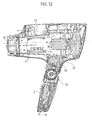
- FIGS. 12 to 14 are views illustrating structures of hair care devices each including the heater of the present invention.
- FIG. 12 is a cross-sectional view of a hair dryer
- FIG. 13A is a side view of a hair iron
- FIG. 13B is a cross-sectional view of the hair iron illustrated in FIG. 13A
- FIG. 14 is a cross-sectional view of a hair brush.
- the hair dryer as the hair care device includes a cavity within a case 12 forming an outer wall thereof.
- an electrical part 13 constituting the heater of the present invention is arranged and accommodated.
- the electric part 13 is supplied with commercial power through a power cord 14.
- the power supply is turned on/off through the body switch section 2, which is provided for a grip 15 that a user grips with his/her hand.
- the heating section 4 is composed of, for example, a belt-shaped or a corrugated plate-shaped electric resistor which is wound along the internal surface of an inner cylinder 17 and warms air blowing out from an outlet opening 16.
- the hair iron as the hair care device includes arm sections 19a and 19b, which are coupled to each other with a rotational coupling portion 18 and are pivotally unfolded substantially in a V-shape. Hair is sandwiched in a holding section 20 provided between top halves of the arm portions 19a and 19b and is heated by the heater section 4 for hair styling. There is a cavity formed within a case 21 forming an outer wall of the hair iron. In the cavity, an electrical part 22 constituting the heater of the present invention is positioned and accommodated. The electric part 22 is supplied with commercial power through a power cord 23. The power supply to the hair iron is turned on/off with the body switch section 2, which is provided for the arm section 19b that a user grips with his/her hand.
- the hair brush as the hair care device has a stick form.
- a user grips a grip section 24 and puts a brush section 26, which is provided for a top half 25, on hair for hair styling.
- an electrical part 28 constituting the heater of the present invention is arranged and accommodated.
- the electric part 28 is supplied with commercial power through a power cord 29.
- the power supply to the hair brush is turned on/off with the body switch section 2, which is provided for the grip section 24.
- the brush section 26 includes air blowing holes 31 at individual feet of a plurality of bristles 30.
- the heating section 4 which warms air blown out from the air blowing holes 31. by a fan 32, is arranged within the cavity formed within the case 27.
- the hair care devices can be reduced in size. Furthermore, the hair care devices are configured to have low standby power consumption and can be provided inexpensively.
Landscapes
- Engineering & Computer Science (AREA)
- Physics & Mathematics (AREA)
- Thermal Sciences (AREA)
- Chemical & Material Sciences (AREA)
- Combustion & Propulsion (AREA)
- Mechanical Engineering (AREA)
- General Engineering & Computer Science (AREA)
- Control Of Resistance Heating (AREA)
- Cleaning And Drying Hair (AREA)
Applications Claiming Priority (1)
| Application Number | Priority Date | Filing Date | Title |
|---|---|---|---|
| JP2009153533A JP2011005152A (ja) | 2009-06-29 | 2009-06-29 | 加熱装置及びそれを備えた髪ケア装置 |
Publications (1)
| Publication Number | Publication Date |
|---|---|
| EP2282138A2 true EP2282138A2 (de) | 2011-02-09 |
Family
ID=42381130
Family Applications (1)
| Application Number | Title | Priority Date | Filing Date |
|---|---|---|---|
| EP10166108A Withdrawn EP2282138A2 (de) | 2009-06-29 | 2010-06-16 | Erhitzer und Haarpflegevorrichtung damit |
Country Status (4)
| Country | Link |
|---|---|
| EP (1) | EP2282138A2 (de) |
| JP (1) | JP2011005152A (de) |
| CN (1) | CN101938858B (de) |
| RU (1) | RU2010126464A (de) |
Cited By (1)
| Publication number | Priority date | Publication date | Assignee | Title |
|---|---|---|---|---|
| CN114711527A (zh) * | 2022-03-10 | 2022-07-08 | 广东精装照明有限公司 | 一种自切换状态的吹风机集成电路 |
Families Citing this family (1)
| Publication number | Priority date | Publication date | Assignee | Title |
|---|---|---|---|---|
| CN111449398A (zh) * | 2020-04-10 | 2020-07-28 | 揭阳市恩美五金电器实业有限公司 | 一种带温度检测的吹风机 |
Citations (1)
| Publication number | Priority date | Publication date | Assignee | Title |
|---|---|---|---|---|
| JPH07329545A (ja) | 1994-06-07 | 1995-12-19 | Hitachi Home Tec Ltd | 車載用電気暖房の制御回路 |
Family Cites Families (5)
| Publication number | Priority date | Publication date | Assignee | Title |
|---|---|---|---|---|
| JP3264597B2 (ja) * | 1995-02-27 | 2002-03-11 | 株式会社東芝 | ドラム式乾燥機 |
| JPH11329760A (ja) * | 1998-05-20 | 1999-11-30 | Sony Corp | 電源装置 |
| CN2744214Y (zh) * | 2004-06-28 | 2005-12-07 | 合基实业有限公司 | 宽调节范围电吹风机 |
| JP2006024537A (ja) * | 2004-07-09 | 2006-01-26 | Rkc Instrument Inc | 電力制御装置および電力制御方法 |
| CN2722549Y (zh) * | 2004-08-30 | 2005-08-31 | 胡小连 | 红外自动控温电热板 |
-
2009
- 2009-06-29 JP JP2009153533A patent/JP2011005152A/ja not_active Withdrawn
-
2010
- 2010-06-16 EP EP10166108A patent/EP2282138A2/de not_active Withdrawn
- 2010-06-28 CN CN201010218469.4A patent/CN101938858B/zh not_active Expired - Fee Related
- 2010-06-28 RU RU2010126464/12A patent/RU2010126464A/ru not_active Application Discontinuation
Patent Citations (1)
| Publication number | Priority date | Publication date | Assignee | Title |
|---|---|---|---|---|
| JPH07329545A (ja) | 1994-06-07 | 1995-12-19 | Hitachi Home Tec Ltd | 車載用電気暖房の制御回路 |
Cited By (2)
| Publication number | Priority date | Publication date | Assignee | Title |
|---|---|---|---|---|
| CN114711527A (zh) * | 2022-03-10 | 2022-07-08 | 广东精装照明有限公司 | 一种自切换状态的吹风机集成电路 |
| CN114711527B (zh) * | 2022-03-10 | 2024-05-14 | 宁波鼎高电器科技有限公司 | 一种自切换状态的吹风机集成电路 |
Also Published As
| Publication number | Publication date |
|---|---|
| JP2011005152A (ja) | 2011-01-13 |
| CN101938858A (zh) | 2011-01-05 |
| CN101938858B (zh) | 2013-01-30 |
| RU2010126464A (ru) | 2012-01-10 |
Similar Documents
| Publication | Publication Date | Title |
|---|---|---|
| US12063716B2 (en) | Bipolar triac short detection and safety circuit | |
| JP5119687B2 (ja) | 無停電電源装置、該無停電電源装置に用いられるバッテリ温度調節方法及びバッテリ温度調節制御プログラム | |
| CN100443009C (zh) | 一种具有热反馈及工作状态显示的改进的个人护理装置 | |
| US8680440B2 (en) | Control circuit for controlling heating element power | |
| US10094587B2 (en) | Heat-exchange ventilation device | |
| KR101640450B1 (ko) | 이차전지팩 입출력 및 온도관리 제어장치 및 방법 | |
| JP2014140287A (ja) | 電子機器の温度保護装置 | |
| JP2019521325A (ja) | 熱制御回路診断を有するパーソナル消費者製品及びその方法 | |
| EP2282138A2 (de) | Erhitzer und Haarpflegevorrichtung damit | |
| EP2282139A2 (de) | Erhitzer und Haarpflegevorrichtung damit | |
| CN101212923B (zh) | 马桶座圈装置和具有该马桶座圈装置的马桶装置 | |
| US8698042B2 (en) | Cosmetic applicator device including a heater member | |
| CN114901997B (zh) | 在没有火焰的情况下用于燃气燃烧系统的热电安全装置 | |
| US7291813B1 (en) | Controller for electric article for human body | |
| JP2001095171A (ja) | 充電装置 | |
| JP2013069482A (ja) | Led点灯装置および、これを用いた照明器具,照明システム | |
| KR102503546B1 (ko) | 배터리의 방전에 의해 동작하는 휴대용 전자기기 및 그 휴대용 전자기기의 배터리 성능 저하 방지 방법 | |
| JP2001357982A (ja) | バッテリ式光源装置 | |
| KR20240162741A (ko) | 무정전 전원장치의 배터리 온도 제어장치 및 방법 | |
| KR101080516B1 (ko) | 온도 조절기 및 이를 이용한 온도조절 방법 | |
| CN223297343U (zh) | 一种可断电保护装置及设备 | |
| HK1149161A (en) | Heater and hair care device including the same | |
| KR101129813B1 (ko) | 온도조절장치의 전원 자동 차단 장치 | |
| JP3150873B2 (ja) | 電圧監視装置 | |
| KR20110004725A (ko) | 전원 공급 장치 |
Legal Events
| Date | Code | Title | Description |
|---|---|---|---|
| PUAI | Public reference made under article 153(3) epc to a published international application that has entered the european phase |
Free format text: ORIGINAL CODE: 0009012 |
|
| 17P | Request for examination filed |
Effective date: 20100616 |
|
| AK | Designated contracting states |
Kind code of ref document: A2 Designated state(s): AL AT BE BG CH CY CZ DE DK EE ES FI FR GB GR HR HU IE IS IT LI LT LU LV MC MK MT NL NO PL PT RO SE SI SK SM TR |
|
| AX | Request for extension of the european patent |
Extension state: BA ME RS |
|
| STAA | Information on the status of an ep patent application or granted ep patent |
Free format text: STATUS: THE APPLICATION IS DEEMED TO BE WITHDRAWN |
|
| 18D | Application deemed to be withdrawn |
Effective date: 20130103 |