EP2282023A1 - Abgasanlage mit aktivem Schalldämpfer - Google Patents
Abgasanlage mit aktivem Schalldämpfer Download PDFInfo
- Publication number
- EP2282023A1 EP2282023A1 EP10162973A EP10162973A EP2282023A1 EP 2282023 A1 EP2282023 A1 EP 2282023A1 EP 10162973 A EP10162973 A EP 10162973A EP 10162973 A EP10162973 A EP 10162973A EP 2282023 A1 EP2282023 A1 EP 2282023A1
- Authority
- EP
- European Patent Office
- Prior art keywords
- exhaust system
- vehicle
- exhaust
- connecting pipe
- pipe
- Prior art date
- Legal status (The legal status is an assumption and is not a legal conclusion. Google has not performed a legal analysis and makes no representation as to the accuracy of the status listed.)
- Granted
Links
Images

Classifications
-
- F—MECHANICAL ENGINEERING; LIGHTING; HEATING; WEAPONS; BLASTING
- F01—MACHINES OR ENGINES IN GENERAL; ENGINE PLANTS IN GENERAL; STEAM ENGINES
- F01N—GAS-FLOW SILENCERS OR EXHAUST APPARATUS FOR MACHINES OR ENGINES IN GENERAL; GAS-FLOW SILENCERS OR EXHAUST APPARATUS FOR INTERNAL-COMBUSTION ENGINES
- F01N1/00—Silencing apparatus characterised by method of silencing
- F01N1/06—Silencing apparatus characterised by method of silencing by using interference effect
- F01N1/065—Silencing apparatus characterised by method of silencing by using interference effect by using an active noise source, e.g. speakers
-
- F—MECHANICAL ENGINEERING; LIGHTING; HEATING; WEAPONS; BLASTING
- F01—MACHINES OR ENGINES IN GENERAL; ENGINE PLANTS IN GENERAL; STEAM ENGINES
- F01N—GAS-FLOW SILENCERS OR EXHAUST APPARATUS FOR MACHINES OR ENGINES IN GENERAL; GAS-FLOW SILENCERS OR EXHAUST APPARATUS FOR INTERNAL-COMBUSTION ENGINES
- F01N1/00—Silencing apparatus characterised by method of silencing
- F01N1/02—Silencing apparatus characterised by method of silencing by using resonance
-
- F—MECHANICAL ENGINEERING; LIGHTING; HEATING; WEAPONS; BLASTING
- F01—MACHINES OR ENGINES IN GENERAL; ENGINE PLANTS IN GENERAL; STEAM ENGINES
- F01N—GAS-FLOW SILENCERS OR EXHAUST APPARATUS FOR MACHINES OR ENGINES IN GENERAL; GAS-FLOW SILENCERS OR EXHAUST APPARATUS FOR INTERNAL-COMBUSTION ENGINES
- F01N1/00—Silencing apparatus characterised by method of silencing
- F01N1/02—Silencing apparatus characterised by method of silencing by using resonance
- F01N1/023—Helmholtz resonators
-
- F—MECHANICAL ENGINEERING; LIGHTING; HEATING; WEAPONS; BLASTING
- F16—ENGINEERING ELEMENTS AND UNITS; GENERAL MEASURES FOR PRODUCING AND MAINTAINING EFFECTIVE FUNCTIONING OF MACHINES OR INSTALLATIONS; THERMAL INSULATION IN GENERAL
- F16L—PIPES; JOINTS OR FITTINGS FOR PIPES; SUPPORTS FOR PIPES, CABLES OR PROTECTIVE TUBING; MEANS FOR THERMAL INSULATION IN GENERAL
- F16L55/00—Devices or appurtenances for use in, or in connection with, pipes or pipe systems
- F16L55/02—Energy absorbers; Noise absorbers
- F16L55/033—Noise absorbers
- F16L55/0333—Noise absorbers by means of an active system
-
- F—MECHANICAL ENGINEERING; LIGHTING; HEATING; WEAPONS; BLASTING
- F01—MACHINES OR ENGINES IN GENERAL; ENGINE PLANTS IN GENERAL; STEAM ENGINES
- F01N—GAS-FLOW SILENCERS OR EXHAUST APPARATUS FOR MACHINES OR ENGINES IN GENERAL; GAS-FLOW SILENCERS OR EXHAUST APPARATUS FOR INTERNAL-COMBUSTION ENGINES
- F01N2240/00—Combination or association of two or more different exhaust treating devices, or of at least one such device with an auxiliary device, not covered by indexing codes F01N2230/00 or F01N2250/00, one of the devices being
- F01N2240/20—Combination or association of two or more different exhaust treating devices, or of at least one such device with an auxiliary device, not covered by indexing codes F01N2230/00 or F01N2250/00, one of the devices being a flow director or deflector
-
- F—MECHANICAL ENGINEERING; LIGHTING; HEATING; WEAPONS; BLASTING
- F01—MACHINES OR ENGINES IN GENERAL; ENGINE PLANTS IN GENERAL; STEAM ENGINES
- F01N—GAS-FLOW SILENCERS OR EXHAUST APPARATUS FOR MACHINES OR ENGINES IN GENERAL; GAS-FLOW SILENCERS OR EXHAUST APPARATUS FOR INTERNAL-COMBUSTION ENGINES
- F01N2260/00—Exhaust treating devices having provisions not otherwise provided for
- F01N2260/02—Exhaust treating devices having provisions not otherwise provided for for cooling the device
- F01N2260/022—Exhaust treating devices having provisions not otherwise provided for for cooling the device using air
-
- F—MECHANICAL ENGINEERING; LIGHTING; HEATING; WEAPONS; BLASTING
- F01—MACHINES OR ENGINES IN GENERAL; ENGINE PLANTS IN GENERAL; STEAM ENGINES
- F01N—GAS-FLOW SILENCERS OR EXHAUST APPARATUS FOR MACHINES OR ENGINES IN GENERAL; GAS-FLOW SILENCERS OR EXHAUST APPARATUS FOR INTERNAL-COMBUSTION ENGINES
- F01N2260/00—Exhaust treating devices having provisions not otherwise provided for
- F01N2260/02—Exhaust treating devices having provisions not otherwise provided for for cooling the device
- F01N2260/024—Exhaust treating devices having provisions not otherwise provided for for cooling the device using a liquid
-
- F—MECHANICAL ENGINEERING; LIGHTING; HEATING; WEAPONS; BLASTING
- F01—MACHINES OR ENGINES IN GENERAL; ENGINE PLANTS IN GENERAL; STEAM ENGINES
- F01N—GAS-FLOW SILENCERS OR EXHAUST APPARATUS FOR MACHINES OR ENGINES IN GENERAL; GAS-FLOW SILENCERS OR EXHAUST APPARATUS FOR INTERNAL-COMBUSTION ENGINES
- F01N2260/00—Exhaust treating devices having provisions not otherwise provided for
- F01N2260/20—Exhaust treating devices having provisions not otherwise provided for for heat or sound protection, e.g. using a shield or specially shaped outer surface of exhaust device
Definitions
- the present invention relates to an exhaust system for an internal combustion engine, in particular of a motor vehicle.
- the invention also relates to a vehicle, in particular a passenger car, with an internal combustion engine and with such an exhaust system.
- An exhaust system usually comprises an exhaust pipe, which leads away an exhaust gas flow from the internal combustion engine during operation of the internal combustion engine.
- exhaust treatment facilities such.
- silencers and catalysts be involved.
- passive silencers By resonance, absorption, interference and reflection work to dampen the airborne sound transported in the exhaust pipe.
- active silencers work with at least one loudspeaker to generate targeted counter-noise. This leads to a more or less effective extinction of the sound to be damped.
- a plurality of motor vehicles in particular passenger cars, have a front engine, ie an internal combustion engine, which is accommodated in a front-side engine compartment of the vehicle.
- a front engine ie an internal combustion engine
- an exhaust system that works with passive mufflers, a comparatively large acoustic length.
- conventional exhaust systems extend from the front-mounted internal combustion engine to the rear of the vehicle, where there is a tailpipe of the exhaust system.
- Exhaust systems for vehicles with front engine in which the tailpipe laterally between a front axle and a Rear axle of the vehicle is arranged, so-called.
- “Side-Pipes” work with large-volume mufflers to within the muffler z. B. by multiple deflection to realize the aforementioned large acoustic length.
- exhaust systems of vehicles with rear engine work with relatively large volume mufflers.
- active silencer In order to reduce energy consumption and pollutant emissions in motor vehicles, there is a desire to build the vehicle easier. Accordingly, there are also considerations, instead of the large-volume passive silencer, to use active silencer, which have a significantly reduced volume and a significantly reduced weight.
- the problem is, however, the fact that the speakers used in the active mufflers have only a comparatively low heat resistance, which in any case is below the usual exhaust gas temperatures.
- active silencers can be connected in vehicles with front engine in the rear of the exhaust system, so to speak, as a rear muffler, since the exhaust gases are already cooled sufficiently far to the end of such long exhaust systems. A shortening of the exhaust system performed to save weight would result in a positioning of the active muffler relatively close to the internal combustion engine. Close to the engine, the exhaust gases are particularly hot, which increases the risk of damaging the active silencer.
- the present invention is concerned with the problem of providing an improved embodiment for an exhaust system or for a motor vehicle equipped therewith, which is distinguished, in particular, by the fact that the risk of thermal damage to the active silencer is reduced. This is intended in particular the possibility of a motor near positioning of the active silencer be opened. In addition, a particularly easy to build exhaust system should be feasible.
- the invention is based on the general idea to use a connecting pipe, via which the active muffler is acoustically connected to the exhaust pipe leading exhaust. Furthermore, this connecting pipe should be cooled.
- the use of such a connecting tube prevents direct loading of the active muffler with the exhaust gas flow conducted in the exhaust pipe, whereby the thermal load of the muffler is significantly reduced.
- the exhaust gas moves substantially only due to the pressure pulsations of the sound transported in the exhaust.
- the "standing" in the connecting pipe gas volume acts as a thermal insulation.
- the cooling of the connecting pipe leads to a further significant reduction of heat transfer from the exhaust pipe to the muffler.
- the connecting pipe forms a heat sink, which effectively prevents or at least significantly reduces heat transfer from the exhaust pipe to the muffler via the connecting pipe.
- the proposed measures thus reduce the thermal load of the active muffler or arranged therein, thermally sensitive components such. B. speaker and speaker drive and possibly speaker control. This makes it possible in particular, the active Connect muffler via the cooled connecting pipe with a comparatively small distance from the engine to the exhaust pipe. This also opens up the possibility of shortening the exhaust system downstream of the active silencer significantly, which can realize a significant weight saving.
- the connecting tube may have cooling ribs on its outer side.
- Such cooling fins increase the heat radiation available surface of the connecting pipe, which improves the cooling of the connecting pipe due to the temperature difference to the environment.
- the connecting tube may have on its inside cooling fins and / or turbulators.
- the connecting tube may be produced of a material which has a particularly high thermal conductivity, such. As aluminum or copper or corresponding Al or Cu alloys.
- the connecting pipe can be arranged on or in the vehicle so that it is exposed to an air flow during operation of the vehicle.
- an air flow By such an air flow, the heat output is improved on the outside of the connecting pipe to the environment or to the air flow.
- the cooling effect of the connecting pipe is thereby also improved.
- Such an air flow may, for example, be caused by the driving operation of the vehicle, so-called airstream.
- the connecting pipe can be at a location exposed to the airstream, z. B. in the region of a subfloor of the vehicle may be arranged.
- blower In addition or as an alternative to these passive measures for cooling the connecting pipe, it is also possible, with the aid of a blower, to generate such an air flow for acting on the connecting pipe. Blowers are used in vehicles, in particular in air-liquid heat exchangers, so-called coolers used. For cooling the connecting pipe, it is now possible to deflect an air flow generated with the aid of such an already existing blower at least partially or to position the connecting pipe in such a way that the desired air flow is applied to the connecting pipe. Alternatively, it is also possible to provide a separate blower for generating the cooling air flow for the connecting pipe.
- the connecting pipe may be coupled heat-transmittingly with a cooling circuit in which a coolant circulates. Preference is given to liquid coolant, whereby an intense heat transfer can be realized.
- the connecting pipe can be configured as a heat exchanger which media-separated and heat-transmitting coupled a gas path with a liquid path and its gas path acoustically connects the housing of the muffler with the exhaust pipe and the liquid path is integrated into the cooling circuit.
- connecting tube cooling, z. B. by means of air flow and / or cooling circuit, in addition to be used for cooling a housing of the muffler, whereby the protection of the components arranged therein is improved against overheating.
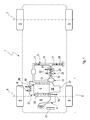
- Fig. 1 includes a motor vehicle 1, which is preferably a passenger car, an internal combustion engine 2 and an exhaust system 3 for discharging exhaust gases from the internal combustion engine 2, which are generated during operation of the internal combustion engine 2 thereof. Furthermore, in Fig. 1 a fresh air system 4 for supplying the internal combustion engine 2 with fresh air and vehicle wheels 5 indicated.
- a first dot-dash line indicates a front axle 6 around which the in Fig. 1 Rotate left front wheels 5 of the vehicle 1 shown.
- a second dot-dash line indicates a rear axle 7 about which the in Fig. 1 Right rear wheels 5 of the vehicle 1 rotate.
- the internal combustion engine 2 is arranged on the vehicle 1 in an engine compartment 8, which is arranged in the vehicle 1 on the front side, that is to say in a front region 9 of the vehicle 1.
- the vehicle 1 is thus equipped with a front engine.
- the exhaust system 3 has accordingly the FIGS. 1 to 3 at least one exhaust pipe 10. During operation of the internal combustion engine 2, this results in an exhaust gas flow 11, indicated by arrows, away from the internal combustion engine 2. Furthermore, the exhaust system 3 is equipped with at least one active muffler 12. This contains in a housing 13 active components, which are not shown here and are to protect against overheating. These components are, for example, a loudspeaker, a loudspeaker driver or loudspeaker drive and possibly a control or control circuit and / or power circuit. An electrical connection for the electrical components of the muffler 12 is in Fig. 2 denoted by 14.
- the housing 13 of the muffler 12 is connected via a connecting tube 15 to the exhaust pipe 10, such that an acoustic coupling arises in terms of airborne sound.
- airborne sound transported in the exhaust pipe 10 can reach the silencer 12 through the connecting pipe 15.
- counter-sound generated by the active components of the muffler 12 can pass through the connecting pipe 15 to the exhaust pipe 10 or into the exhaust pipe 10.
- the connecting pipe 15 is cooled. Both active and passive cooling are possible. Active and passive cooling measures can be used cumulatively or alternatively.
- a fan 17 may be provided, which in Fig. 1 is shown simplified. Such a fan 17 may be present in the vehicle 1, in particular in the engine compartment 8, in any case, for example, to apply a cooling air flow to a main cooler of a machine cooling circuit 18, not shown here.
- the machine cooling circuit 18, which is shown here only in a simplified manner, serves in the usual way for cooling the internal combustion engine 2.
- blower 17 for generating the air flow 16 can be used to cool the connecting pipe 15.
- the connecting tube 15 has its own fan 17th
- Particularly expedient is a development in which the housing 13 of the muffler 12 is arranged in or on the vehicle 1 so that the housing 13 of said air flow 16 is exposed, so that connecting tube 15 and housing 13 acted upon together with the cooling air flow are.
- the connecting pipe 15 may be equipped with cooling ribs 19 on its outside.
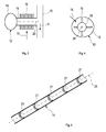
- These cooling ribs 19 can be made correspondingly with respect to a longitudinal axis 20 of the connecting tube 15 Fig. 3 extend in the circumferential direction.
- the cooling fins 19 are designed annular. It is also according to Fig. 4 conceivable to orient the cooling fins 19 parallel to the longitudinal axis 20 of the connecting tube 15. They then form ridge-shaped projecting longitudinal ribs.
- Fig. 5 additionally or alternatively to the arranged on the outside of the connecting tube 15 cooling fins 19 possible to equip the connecting tube 15 on its inside with cooling fins 21.
- cooling fins 19 are indicated. These can be produced, for example, by beads, which are introduced on the outside of the connecting tube 15.
- turbulators can also be arranged on the inside of the connecting pipe 15, which can likewise realize an improvement of the heat transfer from the gas volume in the interior of the connecting pipe 15 and the connecting pipe 15.
- the vehicle 1, in particular in the engine compartment 8, can have corresponding air guide elements. The same applies to a targeted flow guidance in the event that a blower 17 is used to generate the air flow 16.
- Fig. 1 may be provided in a particularly advantageous embodiment, to couple the connecting pipe 15 with a cooling circuit 22 to transmit heat.
- this cooling circuit 22 circulates a coolant in which it is in particular is a liquid coolant.
- the connecting pipe 15 may be at least partially configured as a heat exchanger 23 having a direction indicated by a double arrow gas path 24 and a liquid path 25 and media-separated coupled heat transfer with each other.
- the gas path 24 in this case connects the housing 13 to the exhaust pipe 10, such that the desired acoustic coupling takes place via this gas path 24.
- the liquid path 25 of this heat exchanger or heat exchanger 23 is incorporated in said cooling circuit 22.
- the cooling circuit 22, which is used for cooling the connecting pipe 15, may be a cooling circuit 22 designed separately for the connecting pipe 15 in the vehicle 1. As a result, the required cooling capacity can be optimally ensured.
- this cooling circuit 22 is expediently a branch or section of a cooling circuit already present in the vehicle 1 anyway.
- the cooling circuit 22 may be a branch or section of the machine cooling circuit 18.
- the internal combustion engine 2 is integrated in this engine cooling circuit 18.
- an exhaust gas recirculation cooler 26 of an exhaust gas recirculation system 27 may be incorporated in the engine cooling circuit 18 which is coupled to the cooling circuit 22 for cooling the connection pipe 15.
- a charge air cooler not shown here can be integrated, which cools the charged fresh air when using a charging device.
- the engine 2 and / or the exhaust gas recirculation cooler 26 and / or the intercooler can be coupled in the said engine cooling circuit 18, which is coupled to the cooling circuit 22 provided for cooling the connecting pipe 15 and / or at least one further vehicle-side radiator is incorporated or are.
- the housing 13 of the muffler 12 with said cooling circuit 22 is heat-coupled coupled, which is provided for the cooling of the connecting pipe 15.
- the housing 13 may have a double-walled casing, which is bound into the respective cooling circuit 22, as a result of which the housing 13 can be flushed or flowed through by the respective coolant.
- the muffler 12 is preferably arranged together with the connecting pipe 15 in the engine compartment 8 of the vehicle 1.
- the active muffler 12 is extremely compact, making it possible to accommodate it in the engine compartment 8, so close to the internal combustion engine 2. This also makes it possible to shorten the exhaust system 3 extremely.
- an end pipe 28 of the exhaust system 3, through which the exhaust gas flow 11 exits into an environment of the vehicle 1, can be arranged between the front axle 6 and the rear axle 7, and expediently on a subfloor of the vehicle 1, not shown here possible to arrange the tailpipe 28 in the engine compartment 8, whereby the exhaust system 3 is even shorter.
- the housing 13 has a sound exit opening 29, through which the counter sound generated by the loudspeaker exits from the housing 13.
- the connecting tube 15 is connected to this sound outlet opening 29 in order to achieve the desired acoustic coupling between the muffler 12 and the exhaust pipe 10.
- the connecting pipe 15 is connected via a connecting or connecting piece 30 to the exhaust pipe 10.
- This connecting piece 30 can be designed, for example, as a T-piece.
- the connector 30 is designed as a Y-piece.
- the muffler 12 can be realized together with the connecting pipe 15 as a preassembled unit. As a result, the assembly of the exhaust system 3 is simplified.
- the silencer 12 in particular via its housing 13, may be connected to a gearbox block 31 of a gearbox 32, which is attached to the internal combustion engine 2.
- muffler 12 may be attached to an engine block 33 of the engine 2.
Landscapes
- Engineering & Computer Science (AREA)
- General Engineering & Computer Science (AREA)
- Mechanical Engineering (AREA)
- Chemical & Material Sciences (AREA)
- Combustion & Propulsion (AREA)
- Exhaust Silencers (AREA)
- Cooling, Air Intake And Gas Exhaust, And Fuel Tank Arrangements In Propulsion Units (AREA)
Abstract
Description
- Die vorliegende Erfindung betrifft eine Abgasanlage für eine Brennkraftmaschine, insbesondere eines Kraftfahrzeugs. Die Erfindung betrifft außerdem ein Fahrzeug, insbesondere einen Personenkraftwagen, mit einer Brennkraftmaschine und mit einer derartigen Abgasanlage.
- Eine Abgasanlage umfasst üblicherweise ein Abgasrohr, das im Betrieb der Brennkraftmaschine einen Abgasstrom von der Brennkraftmaschine wegführt. In dieses Abgasrohr können Abgasbehandlungseinrichtungen, wie z. B. Partikelfilter, Schalldämpfer und Katalysatoren, eingebunden sein. Bei Schalldämpfern kommen vorwiegend passive Schalldämpfer zur Anwendung, die bspw. mittels Resonanz, Absorption, Interferenz und Reflexion arbeiten, um den im Abgasrohr transportierten Luftschall zu dämpfen. Im Unterschied dazu arbeiten aktive Schalldämpfer mit mindestens einem Lautsprecher, um gezielt Gegenschall zu erzeugen. Hierdurch kommt es zu einer mehr oder weniger effektiven Auslöschung des zu bedämpfenden Schalls.
- Eine Vielzahl von Kraftfahrzeugen, insbesondere Personenkraftwagen, besitzen einen Frontmotor, also eine Brennkraftmaschine, die in einem frontseitigen Motorraum des Fahrzeugs untergebracht ist. Um die für Personenkraftwagen vorgeschriebenen Lärmschutzbestimmungen einhalten zu können, braucht eine Abgasanlage, die mit passiven Schalldämpfern arbeitet, eine vergleichsweise große akustische Länge. Dementsprechend erstrecken sich herkömmliche Abgasanlagen von der frontseitig angeordneten Brennkraftmaschine bis zum Fahrzeugheck, wo sich ein Endrohr der Abgasanlage befindet. Abgasanlagen für Fahrzeuge mit Frontmotor, bei denen das Endrohr seitlich zwischen einer Vorderachse und einer Hinterachse des Fahrzeugs angeordnet ist, sog. "Side-Pipes", arbeiten mit großvolumigen Schalldämpfern, um innerhalb des Schalldämpfers z. B. durch Mehrfachumlenkung die zuvor genannte, große akustische Länge zu realisieren. Ebenso arbeiten Abgasanlagen von Fahrzeugen mit Heckmotor mit relativ großvolumigen Schalldämpfern.
- Um bei Kraftfahrzeugen den Energieverbrauch und die Schadstoffemissionen zu reduzieren, besteht der Wunsch, das Fahrzeug leichter zu bauen. Dementsprechend gibt es auch Überlegungen, anstelle der großvolumigen passiven Schalldämpfer, aktive Schalldämpfer einzusetzen, die ein deutlich reduziertes Volumen sowie ein deutlich reduziertes Gewicht besitzen. Problematisch ist dabei jedoch der Umstand, dass die in den aktiven Schalldämpfern verwendeten Lautsprecher nur eine vergleichsweise geringe Hitzebeständigkeit besitzen, die jedenfalls unterhalb der üblichen Abgastemperaturen liegt. Grundsätzlich können aktive Schalldämpfer bei Fahrzeugen mit Frontmotor im Heckbereich an die Abgasanlage, also quasi als Nachschalldämpfer angeschlossen werden, da sich die Abgase bis zum Ende derartiger langer Abgasanlagen in der Regel bereits hinreichend weit abgekühlt sind. Eine zur Gewichtseinsparung durchgeführte Verkürzung der Abgasanlage würde eine Positionierung des aktiven Schalldämpfers relativ nahe an der Brennkraftmaschine zur Folge haben. In Motornähe sind die Abgase jedoch besonders heiß, was die Gefahr einer Beschädigung des aktiven Schalldämpfers erhöht.
- Die vorliegende Erfindung beschäftigt sich mit dem Problem, für eine Abgasanlage bzw. für ein damit ausgestattetes Kraftfahrzeug, eine verbesserte Ausführungsform anzugeben, die sich insbesondere dadurch auszeichnet, dass die Gefahr einer thermischen Beschädigung des aktiven Schalldämpfers reduziert ist. Hierdurch soll insbesondere die Möglichkeit einer motornahen Positionierung des aktiven Schalldämpfers eröffnet werden. Außerdem soll eine besonders leicht zu bauende Abgasanlage realisierbar sein.
- Dieses Problem wird erfindungsgemäß durch die Gegenstände der unabhängigen Ansprüche gelöst. Vorteilhafte Ausführungsformen sind Gegenstand der abhängigen Ansprüche.
- Die Erfindung beruht auf dem allgemeinen Gedanken, ein Verbindungsrohr zu verwenden, über das der aktive Schalldämpfer akustisch an das Abgas führende Abgasrohr angeschlossen ist. Ferner soll dieses Verbindungsrohr gekühlt sein. Die Verwendung eines derartigen Verbindungsrohres verhindert eine direkte Beaufschlagung des aktiven Schalldämpfers mit der im Abgasrohr geführten Abgasströmung, wodurch auch die thermische Belastung des Schalldämpfers signifikant reduziert ist. In diesem Verbindungsrohr bewegt sich das Abgas im Wesentlichen nur aufgrund der Druckpulsationen des im Abgas transportierten Schalls. In einem Anschlussbereich, in dem das Verbindungsrohr an das Abgasrohr angeschlossen ist, kann es außerdem zu Verwirbelungen und dergleichen kommen, die eine geringfügige, jedoch nicht zum Schalldämpfer hin gerichtete Abgasbewegung erzeugen. Das im Verbindungsrohr "stehende" Gasvolumen wirkt dabei wie eine thermische Isolierung. Die Kühlung des Verbindungsrohrs, die aktiv oder passiv oder sowohl aktiv als auch passiv erfolgen kann, führt zu einer weiteren signifikanten Reduzierung eines Wärmeübergangs vom Abgasrohr zum Schalldämpfer. Durch die Kühlung des Verbindungsrohrs bildet das Verbindungsrohr eine Wärmesenke, die eine Wärmeübertragung vom Abgasrohr zum Schalldämpfer über das Verbindungsrohr effektiv verhindert oder zumindest deutlich reduziert. Die vorgeschlagenen Maßnahmen reduzieren somit die thermische Belastung des aktiven Schalldämpfers bzw. der darin angeordneten, thermisch empfindlichen Komponenten, wie z. B. Lautsprecher und Lautsprecherantrieb sowie ggf. Lautsprechersteuerung. Hierdurch ist es insbesondere möglich, den aktiven Schalldämpfer über das gekühlte Verbindungsrohr mit einem vergleichsweise geringen Abstand zur Brennkraftmaschine an das Abgasrohr anzuschließen. Dies eröffnet außerdem die Möglichkeit, die Abgasanlage stromab des aktiven Schalldämpfers signifikant zu verkürzen, wodurch sich eine nennenswerte Gewichtseinsparung realisieren lässt.
- Entsprechend einer vorteilhaften Ausführungsform kann das Verbindungsrohr an seiner Außenseite Kühlrippen aufweisen. Derartige Kühlrippen vergrößern die zur Wärmeabstrahlung zur Verfügung stehende Oberfläche des Verbindungsrohrs, was die Kühlung des Verbindungsrohrs aufgrund der Temperaturdifferenz zur Umgebung verbessert. Zusätzlich oder alternativ kann das Verbindungsrohr an seiner Innenseite Kühlrippen und/oder Turbulatoren aufweisen. Hierdurch wird der Wärmeübergang vom Abgas, das sich innerhalb des Verbindungsrohrs befindet, zum Verbindungsrohr verbessert, wodurch die thermisch isolierende Wirkung des vom Verbindungsrohr umschlossenen Abgasvolumens verbessert wird. Des Weiteren ist es grundsätzlich möglich, das Verbindungsrohr aus einem Material herzustellen, das eine besonders hohe thermische Leitfähigkeit besitzt, wie z. B. Aluminium oder Kupfer oder entsprechende AI- bzw. Cu-Legierungen.
- Zweckmäßig kann das Verbindungsrohr an bzw. im Fahrzeug so angeordnet werden, dass es bei einem Betrieb des Fahrzeugs einer Luftströmung ausgesetzt ist. Durch eine solche Luftströmung wird die Wärmeabgabe an der Außenseite des Verbindungsrohrs an die Umgebung bzw. an die Luftströmung verbessert. Die Kühlwirkung des Verbindungsrohrs wird dadurch ebenfalls verbessert. Eine derartige Luftströmung kann bspw. durch den Fahrbetrieb des Fahrzeugs entstehen, sog. Fahrtwind. Bspw. kann das Verbindungsrohr hierzu an einer dem Fahrtwind ausgesetzten Stelle, z. B. im Bereich eines Unterbodens des Fahrzeugs, angeordnet sein. Ebenso ist es mit Hilfe entsprechender Strömungsleitmittel möglich, den Fahrtwind bis zu dem Verbindungsrohr zu leiten, um die gewünschte Luftströmung zur Beaufschlagung des Verbindungsrohrs zu erzeugen. Zusätzlich oder alternativ zu diesen passiven Maßnahmen zur Kühlung des Verbindungsrohrs ist es ebenso möglich, mit Hilfe eines Gebläses, einen solchen Luftstrom zur Beaufschlagung des Verbindungsrohrs zu erzeugen. Gebläse kommen bei Fahrzeugen, insbesondere bei Luft-Flüssigkeit-Wärmetauschern, sog. Kühler, zum Einsatz. Zum Kühlen des Verbindungsrohs ist es nun möglich, ein mit Hilfe eines derartigen, ohnehin vorhandenen Gebläses erzeugten Luftstrom zumindest teilweise so abzulenken bzw. das Verbindungsrohr so zu positionieren, dass die gewünschte Luftstrombeaufschlagung des Verbindungsrohrs erfolgt. Alternativ ist es ebenso möglich, zur Erzeugung der kühlenden Luftströmung für das Verbindungsrohr ein eigenes Gebläse vorzusehen.
- Entsprechend einer anderen vorteilhaften Ausführungsform kann das Verbindungsrohr mit einem Kühlkreis wärmeübertragend gekoppelt sein, in dem ein Kühlmittel zirkuliert. Bevorzugt werden dabei flüssige Kühlmittel, wodurch ein intensiver Wärmeübergang realisierbar ist.
- Um die wärmeübertragende Kopplung zwischen Verbindungsrohr und Kühlkreis zu intensivieren, kann das Verbindungsrohr als Wärmetauscher ausgestaltet sein, der einen Gaspfad mit einem Flüssigkeitspfad mediengetrennt und wärmeübertragend koppelt und dessen Gaspfad das Gehäuse des Schalldämpfers mit dem Abgasrohr akustisch verbindet und dessen Flüssigkeitspfad in den Kühlkreis eingebunden ist.
- Zweckmäßig kann die für das Verbindungsrohr vorgesehene Kühlung, z. B. mittels Luftstrom und/oder Kühlkreis, zusätzlich auch zur Kühlung eines Gehäuses des Schalldämpfers genutzt werden, wodurch der Schutz der darin angeordneten Komponenten vor Überhitzung verbessert ist.
- Weitere wichtige Merkmale und Vorteile der Erfindung ergeben sich aus den Unteransprüchen, aus den Zeichnungen und aus der zugehörigen Figurenbeschreibung anhand der Zeichnungen.
- Es versteht sich, dass die vorstehend genannten und die nachstehend noch zu erläuternden Merkmale nicht nur in der jeweils angegebenen Kombination, sondern auch in anderen Kombinationen oder in Alleinstellung verwendbar sind, ohne den Rahmen der vorliegenden Erfindung zu verlassen.
- Bevorzugte Ausführungsbeispiele der Erfindung sind in den Zeichnungen dargestellt und werden in der nachfolgenden Beschreibung näher erläutert, wobei sich gleiche Bezugszeichen auf gleiche oder ähnliche oder funktional gleiche Bauteile beziehen.
- Es zeigen, jeweils schematisch,
- Fig. 1
- eine stark vereinfachte, schaltplanartige Prinzipdarstellung eines Kraftfahrzeugs,
- Fig. 2
- eine perspektivische Ansicht einer Abgasanlage im Bereich eines aktiven Schalldämpfers,
- Fig. 3
- eine stark vereinfachte Prinzipdarstellung der Abgasanlage im Be- reich des aktiven Schalldämpfers,
- Fig. 4
- einen Querschnitt durch ein Verbindungsrohr bei einer speziellen Ausführungsform,
- Fig. 5
- eine perspektivische Ansicht eines Verbindungsrohrs im Längs- schnitt bei einer weiteren Ausführungsform.
- Entsprechend
Fig. 1 umfasst ein Kraftfahrzeug 1, bei dem es sich bevorzugt um einen Personenkraftwagen handelt, eine Brennkraftmaschine 2 sowie eine Abgasanlage 3 zum Abführen von Abgasen von der Brennkraftmaschine 2, die im Betrieb der Brennkraftmaschine 2 von dieser erzeugt werden. Ferner sind inFig. 1 eine Frischluftanlage 4 zur Versorgung der Brennkraftmaschine 2 mit Frischluft sowie Fahrzeugräder 5 angedeutet. Eine erste strichpunktierte Linie deutet eine Vorderachse 6 an, um welche die inFig. 1 links dargestellten Vorderräder 5 des Fahrzeugs 1 rotieren. Eine zweite strichpunktierte Linie deutet eine Hinterachse 7 an, um welche die inFig. 1 rechts dargestellten Hinterräder 5 des Fahrzeugs 1 rotieren. Die Brennkraftmaschine 2 ist am Fahrzeug 1 in einem Motorraum 8 angeordnet, der im Fahrzeug 1 frontseitig, also in einem Frontbereich 9 des Fahrzeugs 1 angeordnet ist. Das Fahrzeug 1 ist somit mit einem Frontmotor ausgestattet. - Die Abgasanlage 3 weist entsprechend den
Figuren 1 bis 3 zumindest ein Abgasrohr 10 auf. Dieses führt im Betrieb der Brennkraftmaschine 2 einen durch Pfeile angedeuteten Abgasstrom 11 von der Brennkraftmaschine 2 weg. Ferner ist die Abgasanlage 3 mit wenigstens einem aktiven Schalldämpfer 12 ausgestattet. Dieser enthält in einem Gehäuse 13 aktive Komponenten, die hier nicht dargestellt sind und die vor einer Überhitzung zu schützen sind. Bei diesen Komponenten handelt es sich bspw. um einen Lautsprecher, um einen Lautsprechertreiber oder Lautsprecherantrieb sowie ggf. um eine Steuerung oder Steuerschaltung und/oder Leistungsschaltung. Ein elektrischer Anschluss für die elektrischen Komponenten des Schalldämpfers 12 ist inFig. 2 mit 14 bezeichnet. Das Gehäuse 13 des Schalldämpfers 12 ist über ein Verbindungsrohr 15 an das Abgasrohr 10 angeschlossen, derart, dass eine akustische Kopplung hinsichtlich Luftschall entsteht. Mit anderen Worten, durch das Verbindungsrohr 15 kann im Abgasrohr 10 transportierter Luftschall zum Schalldämpfer 12 gelangen. Ebenso kann von den aktiven Komponenten des Schalldämpfers 12 generierter Gegenschall durch das Verbindungsrohr 15 zum Abgasrohr 10 bzw. in das Abgasrohr 10 gelangen. - Um die thermische Belastung des Schalldämpfers 12 bzw. seiner aktiven und/oder elektrischen Komponenten zu reduzieren, ist das Verbindungsrohr 15 gekühlt. Dabei kommen sowohl eine aktive als auch eine passive Kühlung in Frage. Aktive und passive Kühlmaßnahmen können dabei kumulativ oder alternativ zur Anwendung kommen.
- Bspw. kann das Verbindungsrohr 15 am Fahrzeug 1 bzw. im Fahrzeug 1 so angeordnet sein, dass es einer in den
Figuren 3 und 4 durch einen Pfeil angedeuteten Luftströmung 16 ausgesetzt ist. Diese Luftströmung 16 kann dabei durch den Fahrbetrieb des Fahrzeugs 1 entstehen, sog. Fahrtwind. Ebenso kann zum Generieren dieser Luftströmung 16 ein Gebläse 17 vorgesehen sein, das inFig. 1 vereinfacht dargestellt ist. Ein derartiges Gebläse 17 kann im Fahrzeug 1, insbesondere in dessen Motorraum 8, ohnehin vorhanden sein, bspw. um einen hier nicht dargestellten Hauptkühler eines Maschinenkühlkreises 18 mit einer kühlenden Luftströmung zu beaufschlagen. Der Maschinenkühlkreis 18, der hier nur vereinfacht dargestellt ist, dient dabei in üblicher Weise zum Kühlen der Brennkraftmaschine 2. Ebenso kann ein anderes, ohnehin am Fahrzeug 1 vorhandenes Gebläse 17 zur Erzeugung der Luftströmung 16 verwendet werden, um das Verbindungsrohr 15 zu kühlen. Ferner ist denkbar, speziell für das Verbindungsrohr 15 ein eigenes Gebläse 17 im Fahrzeug 1 anzuordnen, das ausschließlich für die Erzeugung der Luftströmung 16 zur Beaufschlagung des Verbindungsrohrs 15 vorgesehen ist. Insofern verfügt das Verbindungsrohr 15 über ein eigenes Gebläse 17. - Besonders zweckmäßig ist dabei eine Weiterbildung, bei welcher auch das Gehäuse 13 des Schalldämpfers 12 im bzw. am Fahrzeug 1 so angeordnet ist, dass auch das Gehäuse 13 der besagten Luftströmung 16 ausgesetzt ist, sodass Verbindungsrohr 15 und Gehäuse 13 gemeinsam mit der kühlenden Luftströmung beaufschlagt sind.
- Entsprechend den
Figuren 3 und 4 kann das Verbindungsrohr 15 an seiner Außenseite mit Kühlrippen 19 ausgestattet sein. Diese Kühlrippen 19 können sich bzgl. einer Längsachse 20 des Verbindungsrohrs 15 entsprechendFig. 3 in Umfangsrichtung erstrecken. Die Kühlrippen 19 sind dabei ringförmig ausgestaltet. Ebenso ist es gemäßFig. 4 denkbar, die Kühlrippen 19 parallel zur Längsachse 20 des Verbindungsrohrs 15 zu orientieren. Sie bilden dann stegförmig abstehende Längsrippen. - Zusätzlich oder alternativ ist es gemäß
Fig. 5 zusätzlich oder alternativ zu den an der Außenseite des Verbindungsrohrs 15 angeordneten Kühlrippen 19 möglich, das Verbindungsrohr 15 an seiner Innenseite mit Kühlrippen 21 auszustatten. Im Beispiel sind mehrere, bzgl. der Längsachse 20 ringförmig umlaufende Kühlrippen 21 angedeutet. Diese können bspw. durch Sicken hergestellt werden, die an der Außenseite des Verbindungsrohrs 15 eingebracht werden. Zusätzlich oder alternativ können an der Innenseite des Verbindungsrohrs 15 auch Turbulatoren angeordnet sein, die ebenfalls eine Verbesserung des Wärmeübergangs vom Gasvolumen im Inneren des Verbindungsrohrs 15 und dem Verbindungsrohr 15 realisieren können. - Um die im Fahrbetrieb entstehende Luftströmung gezielt zur Beaufschlagung des Verbindungsrohrs 15 nutzen zu können, kann das Fahrzeug 1, insbesondere im Motorraum 8, entsprechende Luftleitelemente aufweisen. Entsprechendes gilt auch für eine gezielte Strömungsführung für den Fall, dass ein Gebläse 17 zur Erzeugung des Luftstroms 16 verwendet wird.
- Entsprechend
Fig. 1 kann bei einer besonders vorteilhaften Ausführungsform vorgesehen sein, das Verbindungsrohr 15 mit einem Kühlkreis 22 wärmeübertragend zu koppeln. In diesem Kühlkreis 22 zirkuliert ein Kühlmittel, bei dem es sich insbesondere um ein flüssiges Kühlmittel handelt. Entsprechend dem inFig. 1 gezeigten, bevorzugten Beispiel kann das Verbindungsrohr 15 zumindest teilweise als Wärmetauscher 23 ausgestaltet sein, der einen durch einen Doppelpfeil angedeuteten Gaspfad 24 und einen Flüssigkeitspfad 25 aufweist und mediengetrennt miteinander wärmeübertragend koppelt. Der Gaspfad 24 verbindet dabei das Gehäuse 13 mit dem Abgasrohr 10, derart, dass über diesen Gaspfad 24 die gewünschte akustische Kopplung erfolgt. Der Flüssigkeitspfad 25 dieses Wärme-übertragers oder Wärmetauschers 23 ist in den genannten Kühlkreis 22 eingebunden. Hierdurch kann eine intensive Kühlung des Verbindungsrohrs 15 realisiert werden. Ferner ergibt sich dadurch quasi eine thermische Entkopplung des Schalldämpfers 12 vom Abgasrohr 10. - Beim Kühlkreis 22, der zur Kühlung des Verbindungsrohrs 15 verwendet wird, kann es sich um einen separat für das Verbindungsrohr 15 im Fahrzeug 1 ausgebildeten Kühlkreis 22 handeln. Hierdurch kann die erforderliche Kühlleistung optimal gewährleistet werden. Zweckmäßig handelt es sich bei diesem Kühlkreis 22 jedoch um einen Zweig oder Abschnitt eines ohnehin im Fahrzeug 1 bereits vorhandenen Kühlkreises. Bspw. kann es sich beim Kühlkreis 22 um einen Zweig oder Abschnitt des Maschinenkühlkreises 18 handeln. Im Beispiel ist in diesen Maschinenkühlkreis 18 die Brennkraftmaschine 2 eingebunden. Bei einer anderen Ausführungsform kann in den Maschinenkühlkreis 18, der mit dem Kühlkreis 22 zum Kühlen des Verbindungsrohrs 15 gekoppelt ist, ein Abgasrückführkühler 26 einer Abgasrückführanlage 27 eingebunden sein. Ebenso kann in besagten Maschinenkühlkreis 18 ein hier nicht gezeigter Ladeluftkühler eingebunden sein, der bei Verwendung einer Ladeeinrichtung die aufgeladene Frischluft kühlt. Ebenso ist es möglich, dass in besagtem Maschinenkühlkreis 18, der mit dem zur Kühlung des Verbindungsrohrs 15 vorgesehen Kühlkreis 22 gekoppelt ist, die Brennkraftmaschine 2 und/oder der Abgasrückführkühler 26 und/oder der Ladeluftkühler und/oder wenigstens ein weiterer fahrzeugseitiger Kühler eingebunden ist bzw. sind.
- Besonders zweckmäßig ist auch hier eine Ausgestaltung, bei welcher auch das Gehäuse 13 des Schalldämpfers 12 mit besagtem Kühlkreis 22 wärmeübertragend gekoppelt ist, der für die Kühlung des Verbindungsrohrs 15 vorgesehen ist. Bspw. kann das Gehäuse 13 eine doppelwandige Hülle aufweisen, die in den jeweiligen Kühlkreis 22 eingebunden ist, wodurch das Gehäuse 13 vom jeweiligen Kühlmittel umspülbar bzw. durchströmbar ist.
- Entsprechend
Fig. 1 ist der Schalldämpfer 12 zusammen mit dem Verbindungsrohr 15 bevorzugt im Motorraum 8 des Fahrzeugs 1 angeordnet. Der aktive Schalldämpfer 12 baut extrem kompakt, wodurch es möglich ist, ihn im Motorraum 8, also nahe an der Brennkraftmaschine 2 unterzubringen. Hierdurch ist es außerdem möglich, die Abgasanlage 3 extrem zu verkürzen. Bspw. kann ein Endrohr 28 der Abgasanlage 3, durch das die Abgasströmung 11 in eine Umgebung des Fahrzeugs 1 austritt, zwischen der Vorderachse 6 und der Hinterachse 7 angeordnet sein, und zwar zweckmäßig an einem hier nicht gezeigten Unterboden des Fahrzeugs 1. Des Weiteren ist es insbesondere möglich, das Endrohr 28 im Motorraum 8 anzuordnen, wodurch die Abgasanlage 3 noch kürzer wird. - Entsprechend
Fig. 2 besitzt das Gehäuse 13 eine Schallaustrittsöffnung 29, durch die der vom Lautsprecher erzeugte Gegenschall aus dem Gehäuse 13 austritt. Das Verbindungsrohr 15 ist an diese Schallaustrittsöffnung 29 angeschlossen, um die gewünschte akustische Kopplung zwischen Schalldämpfer 12 und Abgasrohr 10 zu erzielen. Im Beispiel derFig. 2 ist das Verbindungsrohr 15 über ein Verbindungs- oder Anschlussstück 30 an das Abgasrohr 10 angeschlossen. Dieses Verbindungsstück 30 kann bspw. als T-Stück ausgestaltet sein. Im Beispiel derFig. 2 ist das Verbindungsstück 30 als Y-Stück ausgestaltet. - Besonders vorteilhaft kann der Schalldämpfer 12 zusammen mit dem Verbindungsrohr 15 als vormontierbare Einheit realisiert werden. Hierdurch wird die Montage der Abgasanlage 3 vereinfacht.
- Gemäß
Fig. 1 kann der Schalldämpfer 12, insbesondere über sein Gehäuse 13, an einem Getriebeblock 31 eines Getriebes 32 angeschlossen sein, das an die Brennkraftmaschine 2 angebaut ist. Ebenso kann Schalldämpfer 12 an einen Motorblock 33 der Brennkraftmaschine 2 angebaut sein.
Claims (15)
- Abgasanlage für eine Brennkraftmaschine (2), insbesondere eines Kraftfahrzeugs (1),- mit mindestens einem Abgasrohr (10), das im Betrieb der Brennkraftmaschine (2) einen Abgasstrom (11) von der Brennkraftmaschine (2) wegführt,- mit mindestens einem aktiven Schalldämpfer (12), dessen Gehäuse (13) über ein Verbindungsrohr (15) an das Abgasrohr (10) akustisch angeschlossen ist,- wobei das Verbindungsrohr (15) aktiv und/oder passiv gekühlt ist.
- Abgasanlage nach Anspruch 1,
dadurch gekennzeichnet,
dass das Verbindungsrohr (15) an seiner Außenseite Kühlrippen (19) aufweist. - Abgasanlage nach Anspruch 1 oder 2,
dadurch gekennzeichnet,
dass das Verbindungsrohr (15) im oder am Fahrzeug (1) so angeordnet ist, dass es einer durch den Fahrbetrieb des Fahrzeugs (1) entstehenden oder einer durch ein am Fahrzeug (1) vorhandenes Gebläse (17) erzeugten Luftströmung (16) ausgesetzt ist. - Abgasanlage nach einem der Ansprüche 1 bis 3,
dadurch gekennzeichnet,
dass dem Verbindungsrohr (15) ein eigenes Gebläse (17) zugeordnet ist, das eine Luftströmung (16) zur Beaufschlagung des Verbindungsrohrs (15) erzeugt. - Abgasanlage nach Anspruch 3 oder 4,
dadurch gekennzeichnet,
dass das Gehäuse (13) des Schalldämpfers (12) im oder am Fahrzeug (1) so angeordnet ist, dass es ebenfalls der zur Beaufschlagung des Verbindungsrohrs (15) vorgesehenen Luftströmung (16) ausgesetzt ist. - Abgasanlage nach einem der Ansprüche 1 bis 5,
dadurch gekennzeichnet,
dass das Verbindungsrohr (15) mit einem Kühlkreis (22) wärmeübertragend gekoppelt ist, in dem ein Kühlmittel zirkuliert. - Abgasanlage nach Anspruch 6,
dadurch gekennzeichnet,
dass das Verbindungsrohr (15) als Wärmetauscher (23) ausgestaltet ist oder in einen Wärmetauscher (23) integriert ist, der einen Gaspfad (24) mit einem Flüssigkeitspfad (25) wärmeübertragend koppelt und dessen Gaspfad (24) das Gehäuse (13) des Schalldämpfers (12) mit dem Abgasrohr (10) akustisch verbindet und dessen Flüssigkeitspfad (25) in den Kühlkreis (22) eingebunden ist. - Abgasanlage nach Anspruch 6 oder 7,
dadurch gekennzeichnet,
dass der mit dem Verbindungsrohr (15) gekoppelte Kühlkreis (22) durch einen Zweig oder Abschnitt eines Maschinenkühlkreises (18) gebildet ist, in den die Brennkraftmaschine (2) und/oder ein Abgasrückführkühler (26) und/oder ein Ladeluftkühler eingebunden ist/sind. - Abgasanlage nach einem der Ansprüche 6 bis 8,
dadurch gekennzeichnet,
dass das Gehäuse (13) des Schalldämpfers (12) ebenfalls mit dem zur Kühlung des Verbindungsrohrs (15) vorgesehenen Kühlkreis (22) wärmeübertragend gekoppelt ist. - Abgasanlage nach einem der Ansprüche 1 bis 9,
dadurch gekennzeichnet,
dass das Verbindungsrohr (15) an seiner Innenseite Kühlrippen (21) und/oder Turbulatoren aufweist. - Abgasanlage nach einem der Ansprüche 1 bis 10,
dadurch gekennzeichnet,
dass im Einbauzustand der Abgasanlage (3) der Schalldämpfer (12) und das Verbindungsrohr (15) in einem Motorraum (8) des Fahrzeugs (1) angeordnet sind, in dem auch die Brennkraftmaschine (2) angeordnet ist. - Abgasanlage nach einem der Ansprüche 1 bis 11,
dadurch gekennzeichnet,
dass im Einbauzustand der Abgasanlage (3) ein Endrohr (28) der Abgasanlage (3), durch welches das Abgas in eine Umgebung des Fahrzeugs (1) austritt, in einem Motorraum (3) angeordnet ist, in dem auch die Brennkraftmaschine (2) angeordnet ist. - Abgasanlage nach einem der Ansprüche 1 bis 11,
dadurch gekennzeichnet,
dass im Einbauzustand der Abgasanlage (3) ein Endrohr (28) der Abgasanlage (3), durch welches das Abgas in eine Umgebung des Fahrzeugs (1) austritt, zwischen einer Vorderachse (6) und einer Hinterachse (7) des Fahrzeugs (1) an einem Unterboden des Fahrzeugs (1) angeordnet ist. - Abgasanlage nach einem der Ansprüche 11 bis 13,
dadurch gekennzeichnet,
dass der Motorraum (8) in einem Frontbereich (9) des Fahrzeugs (1) ausgebildet ist. - Fahrzeug, insbesondere Personenkraftwagen, mit einer Brennkraftmaschine (2) und einer Abgasanlage (3) nach einem der Ansprüche 1 bis 14.
Applications Claiming Priority (1)
| Application Number | Priority Date | Filing Date | Title |
|---|---|---|---|
| DE102009031848A DE102009031848A1 (de) | 2009-07-03 | 2009-07-03 | Abgasanlage mit aktivem Schalldämpfer |
Publications (2)
| Publication Number | Publication Date |
|---|---|
| EP2282023A1 true EP2282023A1 (de) | 2011-02-09 |
| EP2282023B1 EP2282023B1 (de) | 2015-05-06 |
Family
ID=42542749
Family Applications (1)
| Application Number | Title | Priority Date | Filing Date |
|---|---|---|---|
| EP20100162973 Not-in-force EP2282023B1 (de) | 2009-07-03 | 2010-05-17 | Abgasanlage mit aktivem Schalldämpfer |
Country Status (4)
| Country | Link |
|---|---|
| US (1) | US8360192B2 (de) |
| EP (1) | EP2282023B1 (de) |
| CN (1) | CN101943041B (de) |
| DE (1) | DE102009031848A1 (de) |
Cited By (1)
| Publication number | Priority date | Publication date | Assignee | Title |
|---|---|---|---|---|
| FR3055659A1 (fr) * | 2016-09-06 | 2018-03-09 | Peugeot Citroen Automobiles Sa | Ligne d’echappement compacte munie d’un silencieux |
Families Citing this family (25)
| Publication number | Priority date | Publication date | Assignee | Title |
|---|---|---|---|---|
| DE102011018459A1 (de) | 2011-04-21 | 2012-10-25 | J. Eberspächer GmbH & Co. KG | Übertragungsstreckenkompensator |
| DE102011075643A1 (de) * | 2011-05-11 | 2012-11-15 | J. Eberspächer GmbH & Co. KG | Abgasanlagenkomponente |
| EP2530263B1 (de) | 2011-06-01 | 2013-08-21 | Eberspächer Exhaust Technology GmbH & Co. KG | Antischall-System für Abgasanlagen und Verfahren zum Steuern desselben |
| DE102011106647A1 (de) | 2011-07-05 | 2013-01-10 | J. Eberspächer GmbH & Co. KG | Antischall-system für abgasanlagen und verfahren zum steuern desselben |
| DE102011117495B4 (de) | 2011-11-02 | 2014-08-21 | Eberspächer Exhaust Technology GmbH & Co. KG | Überlastungsschutz für Lautsprecher in Abgasanlagen |
| EP2600342B1 (de) | 2011-12-02 | 2018-05-09 | Eberspächer Exhaust Technology GmbH & Co. KG | Aktive Gestaltung von Abgasgeräuschen |
| DE102011089772B4 (de) * | 2011-12-23 | 2016-09-29 | Eberspächer Exhaust Technology GmbH & Co. KG | Abgasanlage |
| DE102011089774B4 (de) * | 2011-12-23 | 2014-03-27 | Eberspächer Exhaust Technology GmbH & Co. KG | Abgasanlage |
| DE102012109872B4 (de) | 2012-10-16 | 2015-08-27 | Eberspächer Exhaust Technology GmbH & Co. KG | Lautsprecher mit verbesserter thermischer Belastbarkeit |
| US9050887B2 (en) * | 2012-12-27 | 2015-06-09 | Kawasaki Jukogyo Kabushiki Kaisha | Utility vehicle |
| DE102013104307A1 (de) | 2013-04-26 | 2014-10-30 | Eberspächer Exhaust Technology GmbH & Co. KG | System zur Beeinflussung von Abgasgeräuschen und/oder Ansauggeräuschen und/oder Motorgeräuschen |
| EP2797075B1 (de) | 2013-04-26 | 2018-09-12 | Eberspächer Exhaust Technology GmbH & Co. KG | System zur Beeinflussung von Abgasgeräuschen, Motorgeräuschen und/oder Ansauggeräuschen |
| DE102013104810A1 (de) | 2013-05-08 | 2014-11-13 | Eberspächer Exhaust Technology GmbH & Co. KG | Schallerzeuger für ein antischall-system zur beeinflussung von abgasgeräuschen und/oder ansauggeräuschen eines kraftfahrzeugs |
| DE102013010609B4 (de) | 2013-06-25 | 2023-07-27 | Purem GmbH | System zur Beeinflussung von Abgasgeräuschen in einer mehrflutigen Abgasanlage und Kraftfahrzeug |
| DE102013011937B3 (de) | 2013-07-17 | 2014-10-09 | Eberspächer Exhaust Technology GmbH & Co. KG | Schallerzeuger für ein Antischall-System zur Beeinflussung von Abgasgeräuschen und/oder Ansauggeräuschen eines Kraftfahrzeugs |
| EP2915967B1 (de) | 2014-03-04 | 2017-08-02 | Eberspächer Exhaust Technology GmbH & Co. KG | Aktives Design von Auspuffgeräuschen |
| US9394812B2 (en) | 2014-07-09 | 2016-07-19 | Aai Corporation | Attenuating engine noise using a reverse resonator |
| DE102014221326A1 (de) * | 2014-10-21 | 2016-04-21 | Thyssenkrupp Marine Systems Gmbh | Unterseeboot |
| GB2540609B (en) * | 2015-07-23 | 2018-05-16 | Ford Global Tech Llc | An exhaust silencer |
| DE102015217461A1 (de) | 2015-09-11 | 2017-03-16 | Eberspächer Exhaust Technology GmbH & Co. KG | Verbindungsrohr zum Anschließen eines aktiven Schalldämpfers an eine Abgasanlage für eine Brennkraftmaschine |
| DE102015119191A1 (de) | 2015-11-06 | 2017-05-11 | Eberspächer Exhaust Technology GmbH & Co. KG | Schallerzeuger zur Befestigung an einem Fahrzeug zur Beeinflussung von Geräuschen des Fahrzeugs |
| US11472266B2 (en) | 2016-09-16 | 2022-10-18 | Carrier Corporation | Engine exhaust gas cooling system for transport refrigeration system |
| JP7169232B2 (ja) * | 2019-03-08 | 2022-11-10 | 芝浦メカトロニクス株式会社 | 錠剤印刷装置及び錠剤印刷装置の放熱方法 |
| DE102019211619A1 (de) * | 2019-08-02 | 2021-02-04 | Robert Bosch Gmbh | Tanksystem für Fahrzeuge |
| CN114363781A (zh) * | 2022-01-10 | 2022-04-15 | 中国船舶重工集团公司第七一一研究所 | 声源及包括其的动力设备 |
Citations (3)
| Publication number | Priority date | Publication date | Assignee | Title |
|---|---|---|---|---|
| DE4317403A1 (de) * | 1993-05-26 | 1994-12-01 | Nokia Deutschland Gmbh | Anordnung zur aktiven Schalldämpfung |
| US5600106A (en) * | 1994-05-24 | 1997-02-04 | Noise Cancellation Technologies, Inc. | Actively sound reduced muffler having a venturi effect configuration |
| JP2000130145A (ja) * | 1998-10-29 | 2000-05-09 | Osaka Gas Co Ltd | 能動消音装置 |
Family Cites Families (18)
| Publication number | Priority date | Publication date | Assignee | Title |
|---|---|---|---|---|
| US5619020A (en) * | 1991-08-29 | 1997-04-08 | Noise Cancellation Technologies, Inc. | Muffler |
| JPH0598927A (ja) * | 1991-10-11 | 1993-04-20 | Sango:Kk | アクテイブキヤンセルマフラ |
| US5210805A (en) * | 1992-04-06 | 1993-05-11 | Ford Motor Company | Transducer flux optimization |
| US5748749A (en) * | 1993-03-24 | 1998-05-05 | Noise Cancellation Technologies, Inc. | Active noise cancelling muffler |
| IT1267402B1 (it) * | 1994-02-22 | 1997-02-05 | Electronic Sound Attenuation S | Silenziatore attivo per gas di scarico. |
| US5693918A (en) * | 1994-09-06 | 1997-12-02 | Digisonix, Inc. | Active exhaust silencer |
| US6072880A (en) * | 1998-02-27 | 2000-06-06 | Tenneco Automotive Inc. | Modular active silencer with port dish |
| US6005957A (en) * | 1998-02-27 | 1999-12-21 | Tenneco Automotive Inc. | Loudspeaker pressure plate |
| DE19861018C2 (de) * | 1998-12-15 | 2001-06-13 | Fraunhofer Ges Forschung | Gesteuerter akustischer Wellenleiter zur Schalldämpfung |
| US6898289B2 (en) * | 2000-09-20 | 2005-05-24 | Siemens Vdo Automotive Inc. | Integrated active noise attenuation system and fluid reservoir |
| US7293626B2 (en) * | 2001-08-01 | 2007-11-13 | Delphi Technologies, Inc. | Apparatus and method for steering a vehicle |
| US7006639B2 (en) * | 2001-11-20 | 2006-02-28 | Maximilian Hans Hobelsberger | Active noise-attenuating duct element |
| JP4454362B2 (ja) * | 2004-03-30 | 2010-04-21 | 大阪瓦斯株式会社 | 能動型消音装置 |
| DE102004040421A1 (de) * | 2004-08-19 | 2006-03-09 | J. Eberspächer GmbH & Co. KG | Aktiver Abgasschalldämpfer |
| JP4566055B2 (ja) * | 2004-09-10 | 2010-10-20 | フタバ産業株式会社 | 排気熱回収マフラ |
| DE102005041692A1 (de) * | 2005-09-01 | 2007-03-15 | J. Eberspächer GmbH & Co. KG | Schalldämpfer für eine Abgasanlage |
| DE102006042224B3 (de) | 2006-09-06 | 2008-01-17 | J. Eberspächer GmbH & Co. KG | Aktiver Schalldämpfer für eine Abgasanlage |
| DE102008018085A1 (de) * | 2008-04-09 | 2009-10-15 | J. Eberspächer GmbH & Co. KG | Aktiver Schalldämpfer |
-
2009
- 2009-07-03 DE DE102009031848A patent/DE102009031848A1/de not_active Withdrawn
-
2010
- 2010-05-17 EP EP20100162973 patent/EP2282023B1/de not_active Not-in-force
- 2010-06-28 US US12/824,444 patent/US8360192B2/en not_active Expired - Fee Related
- 2010-07-05 CN CN201010217327.6A patent/CN101943041B/zh not_active Expired - Fee Related
Patent Citations (3)
| Publication number | Priority date | Publication date | Assignee | Title |
|---|---|---|---|---|
| DE4317403A1 (de) * | 1993-05-26 | 1994-12-01 | Nokia Deutschland Gmbh | Anordnung zur aktiven Schalldämpfung |
| US5600106A (en) * | 1994-05-24 | 1997-02-04 | Noise Cancellation Technologies, Inc. | Actively sound reduced muffler having a venturi effect configuration |
| JP2000130145A (ja) * | 1998-10-29 | 2000-05-09 | Osaka Gas Co Ltd | 能動消音装置 |
Cited By (1)
| Publication number | Priority date | Publication date | Assignee | Title |
|---|---|---|---|---|
| FR3055659A1 (fr) * | 2016-09-06 | 2018-03-09 | Peugeot Citroen Automobiles Sa | Ligne d’echappement compacte munie d’un silencieux |
Also Published As
| Publication number | Publication date |
|---|---|
| US8360192B2 (en) | 2013-01-29 |
| US20110000734A1 (en) | 2011-01-06 |
| CN101943041B (zh) | 2014-09-10 |
| CN101943041A (zh) | 2011-01-12 |
| EP2282023B1 (de) | 2015-05-06 |
| DE102009031848A1 (de) | 2011-01-05 |
Similar Documents
| Publication | Publication Date | Title |
|---|---|---|
| EP2282023B1 (de) | Abgasanlage mit aktivem Schalldämpfer | |
| EP2027370B1 (de) | Vorrichtung zur beeinflussung einer abgasströmung | |
| EP3105525B1 (de) | Ladeluftkühler für eine frischluftanlage einer brennkraftmaschine | |
| DE102020103196B4 (de) | Kraftfahrzeug mit einer im Heckbereich vorgesehenen Unterbodenverkleidung | |
| EP1327542B1 (de) | Heizgerät und Gehäuse für ein Heizgerät | |
| DE202010003049U1 (de) | Vorrichtung zur Abgaswärmenutzung | |
| WO2015173096A1 (de) | Fahrzeug mit einem verbrennungsmotor und einem abwärmesammelgehäuse | |
| CN206267950U (zh) | 冷却增压空气和过剩燃料的系统及其工作车辆 | |
| EP1431536B1 (de) | Schallwandler für ein Kraftfahrzeug | |
| DE202004015698U1 (de) | Hitzeschild | |
| DE102006011727B3 (de) | Kombiniertes Heizungs-/Warmwassersystem für mobile Anwendungen | |
| DE102008057420A1 (de) | Wärmeübertrager | |
| DE102015217461A1 (de) | Verbindungsrohr zum Anschließen eines aktiven Schalldämpfers an eine Abgasanlage für eine Brennkraftmaschine | |
| DE102009021095B4 (de) | Kraftwagen mit einem Heckmotor | |
| EP1862651B1 (de) | Isoliervorrichtung für ein, insbesondere von einem heißen Medium durchströmbares Maschinenelement | |
| DE102012005987A1 (de) | Abgasanlage für ein Fahrzeug und Verfahren zum Betreiben einer Abgasanlage | |
| WO2015173093A1 (de) | Fahrzeug mit einem verbrennungsmotor und einem abwärmesammeigehäuse, verfahren zum nutzen eines teils der von einem verbrennungsmotor abgegebenen wärme sowie stationäre anordnung, insbesondere blockheizkraftwerk | |
| DE102013004539A1 (de) | Kapselung für einen Motorraum eines Kraftwagens | |
| WO2024017733A1 (de) | Kraftfahrzeug aufweisend temperiervorrichtung | |
| EP4077018B1 (de) | Kompressor- sowie batterie-system für ein kraftfahrzeug | |
| DE102014014423A1 (de) | Anordnungsstruktur eines Abgaswärmetauschers | |
| DE102024123224B4 (de) | Wärmeverteilung für ein Kraftfahrzeug mit einem Koppel-Wärmeübertrager | |
| EP2136047A2 (de) | Wärmeübertrager | |
| WO2014128080A1 (de) | Kraftfahrzeug mit einer abgasanlage | |
| DE19713442C2 (de) | Verbrennungsmotor sowie Schalldämpfervorrichtung dafür |
Legal Events
| Date | Code | Title | Description |
|---|---|---|---|
| PUAI | Public reference made under article 153(3) epc to a published international application that has entered the european phase |
Free format text: ORIGINAL CODE: 0009012 |
|
| AK | Designated contracting states |
Kind code of ref document: A1 Designated state(s): AL AT BE BG CH CY CZ DE DK EE ES FI FR GB GR HR HU IE IS IT LI LT LU LV MC MK MT NL NO PL PT RO SE SI SK SM TR |
|
| AX | Request for extension of the european patent |
Extension state: BA ME RS |
|
| 17P | Request for examination filed |
Effective date: 20110809 |
|
| RAP1 | Party data changed (applicant data changed or rights of an application transferred) |
Owner name: EBERSPAECHER EXHAUST TECHNOLOGY GMBH & CO. KG |
|
| GRAP | Despatch of communication of intention to grant a patent |
Free format text: ORIGINAL CODE: EPIDOSNIGR1 |
|
| INTG | Intention to grant announced |
Effective date: 20150123 |
|
| GRAS | Grant fee paid |
Free format text: ORIGINAL CODE: EPIDOSNIGR3 |
|
| GRAA | (expected) grant |
Free format text: ORIGINAL CODE: 0009210 |
|
| AK | Designated contracting states |
Kind code of ref document: B1 Designated state(s): AL AT BE BG CH CY CZ DE DK EE ES FI FR GB GR HR HU IE IS IT LI LT LU LV MC MK MT NL NO PL PT RO SE SI SK SM TR |
|
| REG | Reference to a national code |
Ref country code: GB Ref legal event code: FG4D Free format text: NOT ENGLISH |
|
| REG | Reference to a national code |
Ref country code: CH Ref legal event code: EP |
|
| REG | Reference to a national code |
Ref country code: IE Ref legal event code: FG4D Free format text: LANGUAGE OF EP DOCUMENT: GERMAN |
|
| REG | Reference to a national code |
Ref country code: AT Ref legal event code: REF Ref document number: 725864 Country of ref document: AT Kind code of ref document: T Effective date: 20150615 |
|
| REG | Reference to a national code |
Ref country code: DE Ref legal event code: R096 Ref document number: 502010009468 Country of ref document: DE Effective date: 20150618 |
|
| REG | Reference to a national code |
Ref country code: NL Ref legal event code: MP Effective date: 20150506 |
|
| REG | Reference to a national code |
Ref country code: LT Ref legal event code: MG4D |
|
| PG25 | Lapsed in a contracting state [announced via postgrant information from national office to epo] |
Ref country code: LT Free format text: LAPSE BECAUSE OF FAILURE TO SUBMIT A TRANSLATION OF THE DESCRIPTION OR TO PAY THE FEE WITHIN THE PRESCRIBED TIME-LIMIT Effective date: 20150506 Ref country code: FI Free format text: LAPSE BECAUSE OF FAILURE TO SUBMIT A TRANSLATION OF THE DESCRIPTION OR TO PAY THE FEE WITHIN THE PRESCRIBED TIME-LIMIT Effective date: 20150506 Ref country code: ES Free format text: LAPSE BECAUSE OF FAILURE TO SUBMIT A TRANSLATION OF THE DESCRIPTION OR TO PAY THE FEE WITHIN THE PRESCRIBED TIME-LIMIT Effective date: 20150506 Ref country code: PT Free format text: LAPSE BECAUSE OF FAILURE TO SUBMIT A TRANSLATION OF THE DESCRIPTION OR TO PAY THE FEE WITHIN THE PRESCRIBED TIME-LIMIT Effective date: 20150907 Ref country code: NO Free format text: LAPSE BECAUSE OF FAILURE TO SUBMIT A TRANSLATION OF THE DESCRIPTION OR TO PAY THE FEE WITHIN THE PRESCRIBED TIME-LIMIT Effective date: 20150806 Ref country code: HR Free format text: LAPSE BECAUSE OF FAILURE TO SUBMIT A TRANSLATION OF THE DESCRIPTION OR TO PAY THE FEE WITHIN THE PRESCRIBED TIME-LIMIT Effective date: 20150506 |
|
| PG25 | Lapsed in a contracting state [announced via postgrant information from national office to epo] |
Ref country code: LV Free format text: LAPSE BECAUSE OF FAILURE TO SUBMIT A TRANSLATION OF THE DESCRIPTION OR TO PAY THE FEE WITHIN THE PRESCRIBED TIME-LIMIT Effective date: 20150506 Ref country code: GR Free format text: LAPSE BECAUSE OF FAILURE TO SUBMIT A TRANSLATION OF THE DESCRIPTION OR TO PAY THE FEE WITHIN THE PRESCRIBED TIME-LIMIT Effective date: 20150807 Ref country code: BG Free format text: LAPSE BECAUSE OF FAILURE TO SUBMIT A TRANSLATION OF THE DESCRIPTION OR TO PAY THE FEE WITHIN THE PRESCRIBED TIME-LIMIT Effective date: 20150806 Ref country code: IS Free format text: LAPSE BECAUSE OF FAILURE TO SUBMIT A TRANSLATION OF THE DESCRIPTION OR TO PAY THE FEE WITHIN THE PRESCRIBED TIME-LIMIT Effective date: 20150906 |
|
| REG | Reference to a national code |
Ref country code: CH Ref legal event code: PL |
|
| PG25 | Lapsed in a contracting state [announced via postgrant information from national office to epo] |
Ref country code: CH Free format text: LAPSE BECAUSE OF NON-PAYMENT OF DUE FEES Effective date: 20150531 Ref country code: DK Free format text: LAPSE BECAUSE OF FAILURE TO SUBMIT A TRANSLATION OF THE DESCRIPTION OR TO PAY THE FEE WITHIN THE PRESCRIBED TIME-LIMIT Effective date: 20150506 Ref country code: LI Free format text: LAPSE BECAUSE OF NON-PAYMENT OF DUE FEES Effective date: 20150531 Ref country code: EE Free format text: LAPSE BECAUSE OF FAILURE TO SUBMIT A TRANSLATION OF THE DESCRIPTION OR TO PAY THE FEE WITHIN THE PRESCRIBED TIME-LIMIT Effective date: 20150506 |
|
| REG | Reference to a national code |
Ref country code: DE Ref legal event code: R097 Ref document number: 502010009468 Country of ref document: DE |
|
| REG | Reference to a national code |
Ref country code: IE Ref legal event code: MM4A |
|
| PG25 | Lapsed in a contracting state [announced via postgrant information from national office to epo] |
Ref country code: PL Free format text: LAPSE BECAUSE OF FAILURE TO SUBMIT A TRANSLATION OF THE DESCRIPTION OR TO PAY THE FEE WITHIN THE PRESCRIBED TIME-LIMIT Effective date: 20150506 Ref country code: RO Free format text: LAPSE BECAUSE OF NON-PAYMENT OF DUE FEES Effective date: 20150506 Ref country code: CZ Free format text: LAPSE BECAUSE OF FAILURE TO SUBMIT A TRANSLATION OF THE DESCRIPTION OR TO PAY THE FEE WITHIN THE PRESCRIBED TIME-LIMIT Effective date: 20150506 Ref country code: SK Free format text: LAPSE BECAUSE OF FAILURE TO SUBMIT A TRANSLATION OF THE DESCRIPTION OR TO PAY THE FEE WITHIN THE PRESCRIBED TIME-LIMIT Effective date: 20150506 Ref country code: MC Free format text: LAPSE BECAUSE OF FAILURE TO SUBMIT A TRANSLATION OF THE DESCRIPTION OR TO PAY THE FEE WITHIN THE PRESCRIBED TIME-LIMIT Effective date: 20150506 |
|
| PLBE | No opposition filed within time limit |
Free format text: ORIGINAL CODE: 0009261 |
|
| STAA | Information on the status of an ep patent application or granted ep patent |
Free format text: STATUS: NO OPPOSITION FILED WITHIN TIME LIMIT |
|
| 26N | No opposition filed |
Effective date: 20160209 |
|
| PG25 | Lapsed in a contracting state [announced via postgrant information from national office to epo] |
Ref country code: IE Free format text: LAPSE BECAUSE OF NON-PAYMENT OF DUE FEES Effective date: 20150517 |
|
| REG | Reference to a national code |
Ref country code: FR Ref legal event code: PLFP Year of fee payment: 7 |
|
| PG25 | Lapsed in a contracting state [announced via postgrant information from national office to epo] |
Ref country code: SI Free format text: LAPSE BECAUSE OF FAILURE TO SUBMIT A TRANSLATION OF THE DESCRIPTION OR TO PAY THE FEE WITHIN THE PRESCRIBED TIME-LIMIT Effective date: 20150506 |
|
| REG | Reference to a national code |
Ref country code: AT Ref legal event code: MM01 Ref document number: 725864 Country of ref document: AT Kind code of ref document: T Effective date: 20150517 |
|
| PG25 | Lapsed in a contracting state [announced via postgrant information from national office to epo] |
Ref country code: AT Free format text: LAPSE BECAUSE OF NON-PAYMENT OF DUE FEES Effective date: 20150517 |
|
| PG25 | Lapsed in a contracting state [announced via postgrant information from national office to epo] |
Ref country code: MT Free format text: LAPSE BECAUSE OF FAILURE TO SUBMIT A TRANSLATION OF THE DESCRIPTION OR TO PAY THE FEE WITHIN THE PRESCRIBED TIME-LIMIT Effective date: 20150506 |
|
| REG | Reference to a national code |
Ref country code: FR Ref legal event code: PLFP Year of fee payment: 8 |
|
| PG25 | Lapsed in a contracting state [announced via postgrant information from national office to epo] |
Ref country code: HU Free format text: LAPSE BECAUSE OF FAILURE TO SUBMIT A TRANSLATION OF THE DESCRIPTION OR TO PAY THE FEE WITHIN THE PRESCRIBED TIME-LIMIT; INVALID AB INITIO Effective date: 20100517 Ref country code: SM Free format text: LAPSE BECAUSE OF FAILURE TO SUBMIT A TRANSLATION OF THE DESCRIPTION OR TO PAY THE FEE WITHIN THE PRESCRIBED TIME-LIMIT Effective date: 20150506 |
|
| PG25 | Lapsed in a contracting state [announced via postgrant information from national office to epo] |
Ref country code: NL Free format text: LAPSE BECAUSE OF FAILURE TO SUBMIT A TRANSLATION OF THE DESCRIPTION OR TO PAY THE FEE WITHIN THE PRESCRIBED TIME-LIMIT Effective date: 20150506 Ref country code: CY Free format text: LAPSE BECAUSE OF FAILURE TO SUBMIT A TRANSLATION OF THE DESCRIPTION OR TO PAY THE FEE WITHIN THE PRESCRIBED TIME-LIMIT Effective date: 20150506 Ref country code: SE Free format text: LAPSE BECAUSE OF FAILURE TO SUBMIT A TRANSLATION OF THE DESCRIPTION OR TO PAY THE FEE WITHIN THE PRESCRIBED TIME-LIMIT Effective date: 20150506 |
|
| PG25 | Lapsed in a contracting state [announced via postgrant information from national office to epo] |
Ref country code: BE Free format text: LAPSE BECAUSE OF NON-PAYMENT OF DUE FEES Effective date: 20150531 |
|
| PG25 | Lapsed in a contracting state [announced via postgrant information from national office to epo] |
Ref country code: TR Free format text: LAPSE BECAUSE OF FAILURE TO SUBMIT A TRANSLATION OF THE DESCRIPTION OR TO PAY THE FEE WITHIN THE PRESCRIBED TIME-LIMIT Effective date: 20150506 |
|
| PG25 | Lapsed in a contracting state [announced via postgrant information from national office to epo] |
Ref country code: LU Free format text: LAPSE BECAUSE OF NON-PAYMENT OF DUE FEES Effective date: 20150517 |
|
| REG | Reference to a national code |
Ref country code: FR Ref legal event code: PLFP Year of fee payment: 9 |
|
| PG25 | Lapsed in a contracting state [announced via postgrant information from national office to epo] |
Ref country code: MK Free format text: LAPSE BECAUSE OF FAILURE TO SUBMIT A TRANSLATION OF THE DESCRIPTION OR TO PAY THE FEE WITHIN THE PRESCRIBED TIME-LIMIT Effective date: 20150506 |
|
| PG25 | Lapsed in a contracting state [announced via postgrant information from national office to epo] |
Ref country code: AL Free format text: LAPSE BECAUSE OF FAILURE TO SUBMIT A TRANSLATION OF THE DESCRIPTION OR TO PAY THE FEE WITHIN THE PRESCRIBED TIME-LIMIT Effective date: 20150506 |
|
| PG25 | Lapsed in a contracting state [announced via postgrant information from national office to epo] |
Ref country code: IT Free format text: LAPSE BECAUSE OF NON-PAYMENT OF DUE FEES Effective date: 20190517 |
|
| REG | Reference to a national code |
Ref country code: DE Ref legal event code: R081 Ref document number: 502010009468 Country of ref document: DE Owner name: PUREM GMBH, DE Free format text: FORMER OWNER: EBERSPAECHER EXHAUST TECHNOLOGY GMBH & CO. KG, 66539 NEUNKIRCHEN, DE |
|
| PGFP | Annual fee paid to national office [announced via postgrant information from national office to epo] |
Ref country code: FR Payment date: 20230517 Year of fee payment: 14 Ref country code: DE Payment date: 20230519 Year of fee payment: 14 |
|
| PGFP | Annual fee paid to national office [announced via postgrant information from national office to epo] |
Ref country code: GB Payment date: 20230522 Year of fee payment: 14 |
|
| REG | Reference to a national code |
Ref country code: DE Ref legal event code: R119 Ref document number: 502010009468 Country of ref document: DE |
|
| GBPC | Gb: european patent ceased through non-payment of renewal fee |
Effective date: 20240517 |
|
| PG25 | Lapsed in a contracting state [announced via postgrant information from national office to epo] |
Ref country code: DE Free format text: LAPSE BECAUSE OF NON-PAYMENT OF DUE FEES Effective date: 20241203 |
|
| PG25 | Lapsed in a contracting state [announced via postgrant information from national office to epo] |
Ref country code: FR Free format text: LAPSE BECAUSE OF NON-PAYMENT OF DUE FEES Effective date: 20240531 |
|
| PG25 | Lapsed in a contracting state [announced via postgrant information from national office to epo] |
Ref country code: GB Free format text: LAPSE BECAUSE OF NON-PAYMENT OF DUE FEES Effective date: 20240517 |