EP2280254A1 - Halterung für ein dünnes Element, eine Quarzmikrowaage, die eine solche Halterung umfasst und ein Probenträger, der eine solche Halterung umfasst - Google Patents
Halterung für ein dünnes Element, eine Quarzmikrowaage, die eine solche Halterung umfasst und ein Probenträger, der eine solche Halterung umfasst Download PDFInfo
- Publication number
- EP2280254A1 EP2280254A1 EP10170625A EP10170625A EP2280254A1 EP 2280254 A1 EP2280254 A1 EP 2280254A1 EP 10170625 A EP10170625 A EP 10170625A EP 10170625 A EP10170625 A EP 10170625A EP 2280254 A1 EP2280254 A1 EP 2280254A1
- Authority
- EP
- European Patent Office
- Prior art keywords
- support
- blade
- shoulder
- passage
- quartz
- Prior art date
- Legal status (The legal status is an assumption and is not a legal conclusion. Google has not performed a legal analysis and makes no representation as to the accuracy of the status listed.)
- Granted
Links
- 239000010453 quartz Substances 0.000 title claims abstract description 63
- VYPSYNLAJGMNEJ-UHFFFAOYSA-N silicon dioxide Inorganic materials O=[Si]=O VYPSYNLAJGMNEJ-UHFFFAOYSA-N 0.000 title claims abstract description 63
- 239000000758 substrate Substances 0.000 claims abstract description 13
- 238000006243 chemical reaction Methods 0.000 claims abstract description 4
- 230000000149 penetrating effect Effects 0.000 claims abstract description 3
- 239000010408 film Substances 0.000 claims description 15
- 239000007788 liquid Substances 0.000 claims description 15
- 238000007789 sealing Methods 0.000 claims description 9
- 229920006362 Teflon® Polymers 0.000 claims description 8
- 239000000463 material Substances 0.000 claims description 6
- 238000001465 metallisation Methods 0.000 claims description 4
- 239000004065 semiconductor Substances 0.000 claims description 4
- 239000010409 thin film Substances 0.000 claims description 4
- 239000011324 bead Substances 0.000 claims description 3
- 230000000284 resting effect Effects 0.000 claims description 3
- 239000006193 liquid solution Substances 0.000 claims description 2
- 238000005259 measurement Methods 0.000 abstract description 5
- 210000004027 cell Anatomy 0.000 description 37
- 210000002105 tongue Anatomy 0.000 description 5
- 239000000126 substance Substances 0.000 description 4
- KRHYYFGTRYWZRS-UHFFFAOYSA-N Fluorane Chemical compound F KRHYYFGTRYWZRS-UHFFFAOYSA-N 0.000 description 2
- 210000005056 cell body Anatomy 0.000 description 2
- 230000006866 deterioration Effects 0.000 description 2
- 238000003487 electrochemical reaction Methods 0.000 description 2
- 238000012423 maintenance Methods 0.000 description 2
- 238000000034 method Methods 0.000 description 2
- BASFCYQUMIYNBI-UHFFFAOYSA-N platinum Chemical compound [Pt] BASFCYQUMIYNBI-UHFFFAOYSA-N 0.000 description 2
- 238000012545 processing Methods 0.000 description 2
- 229910052710 silicon Inorganic materials 0.000 description 2
- 239000010703 silicon Substances 0.000 description 2
- RYGMFSIKBFXOCR-UHFFFAOYSA-N Copper Chemical compound [Cu] RYGMFSIKBFXOCR-UHFFFAOYSA-N 0.000 description 1
- 230000015572 biosynthetic process Effects 0.000 description 1
- 239000004020 conductor Substances 0.000 description 1
- 238000010276 construction Methods 0.000 description 1
- 229910052802 copper Inorganic materials 0.000 description 1
- 239000010949 copper Substances 0.000 description 1
- 230000002950 deficient Effects 0.000 description 1
- 238000000151 deposition Methods 0.000 description 1
- 230000008021 deposition Effects 0.000 description 1
- 238000009826 distribution Methods 0.000 description 1
- 239000003792 electrolyte Substances 0.000 description 1
- 239000011521 glass Substances 0.000 description 1
- 230000003100 immobilizing effect Effects 0.000 description 1
- 238000003780 insertion Methods 0.000 description 1
- 230000037431 insertion Effects 0.000 description 1
- 238000003754 machining Methods 0.000 description 1
- 230000014759 maintenance of location Effects 0.000 description 1
- 238000004519 manufacturing process Methods 0.000 description 1
- 238000000465 moulding Methods 0.000 description 1
- 229910052697 platinum Inorganic materials 0.000 description 1
- 230000001737 promoting effect Effects 0.000 description 1
- 238000012546 transfer Methods 0.000 description 1
Images


Classifications
-
- G—PHYSICS
- G01—MEASURING; TESTING
- G01G—WEIGHING
- G01G3/00—Weighing apparatus characterised by the use of elastically-deformable members, e.g. spring balances
- G01G3/12—Weighing apparatus characterised by the use of elastically-deformable members, e.g. spring balances wherein the weighing element is in the form of a solid body stressed by pressure or tension during weighing
- G01G3/13—Weighing apparatus characterised by the use of elastically-deformable members, e.g. spring balances wherein the weighing element is in the form of a solid body stressed by pressure or tension during weighing having piezoelectric or piezoresistive properties
-
- G—PHYSICS
- G01—MEASURING; TESTING
- G01G—WEIGHING
- G01G3/00—Weighing apparatus characterised by the use of elastically-deformable members, e.g. spring balances
- G01G3/12—Weighing apparatus characterised by the use of elastically-deformable members, e.g. spring balances wherein the weighing element is in the form of a solid body stressed by pressure or tension during weighing
- G01G3/16—Weighing apparatus characterised by the use of elastically-deformable members, e.g. spring balances wherein the weighing element is in the form of a solid body stressed by pressure or tension during weighing measuring variations of frequency of oscillations of the body
- G01G3/165—Constructional details
Definitions
- the present invention relates to a support for a thin element, this thin element being either a substrate on which is deposited a sample in the form of a film, or an element making it possible to carry out measurements such as a quartz for a microbalance to quartz.
- the present invention also relates to a microbalance comprising such a support and to a sample holder comprising such a support.
- the quartz microbalances make it possible to measure the mass of a deposit of material of the order of a few nanograms in a gaseous or liquid medium by measuring the variation of the resonant frequency of the quartz, the quartz being a material having piezoelectric qualities.
- the quartz is covered on both sides with a conductive layer, platinum type.
- Such a microbalance can be coupled to electrochemical systems, called electrochemical cells in which the electrochemical reactions causing the mass variation on the quartz band take place.
- the microbalance comprises a casing in which the quartz band is held.
- the case is mounted on the electrochemical cell.
- the housing is such that one side of the strip is uncovered, the electrochemical bath of the cell coming into contact with this exposed face. It is on this face that the deposition, or, more generally, the electrochemical reactions takes place.
- the housings or supports of the quartz microbalances of the state of the art comprise a large number of parts. For example, they include a large number of screws and reported support members. In addition to the risk of losing one of the parts, especially the screws, the screwing and unscrewing quickly wear the threads. Quite quickly, the assembly is no longer optimal. In addition, their seal is not optimal. In addition, the replacement of quartz is difficult and requires almost complete disassembly of the housing. Each disassembly causes a deterioration of the support, as explained above.
- a support having a housing provided with a shoulder against which is tightly sealed a blade, and by a clamping member applying a force to the blade to hold against the shoulder, and provide a sealed contact of the blade against the shoulder, the face of the blade whose periphery is in contact with the shoulder is intended to come into contact with an active solution.
- the other side is inside the case which is waterproof.
- the clamping element also forms a sealed shutter of the housing and cooperates by screwing with the housing.
- blade means a thin element that can be for example a quartz plate whose thickness is of the order of a few hundred microns or a thin film.
- the disassembly and mounting of the support are very simple, since it has only two parts, the screws being removed.
- the replacement of the thin element is easy. There is therefore no risk of deterioration of the support.
- the seal is obtained simply and effectively by the force applied by the plug on the blade.
- the support can be designed to make the cavity at the blade surface as short as possible.
- the support provides a complete seal on the front and back, so it can be immersed in the solution.
- the second piece may comprise a first plug portion and cooperating by screwing with the first piece, a rod slidably mounted at one end in the first part, a head fixed to a second end of the rod and intended to exert a force on the thin element, and a resilient means mounted in reaction between the head and the first part, so as to exert said axial force on the head in the direction of the shoulder.
- the portion of the passage intended to come into contact with the liquid advantageously has a frustoconical shape, the largest diameter of which is oriented away from the shoulder.
- the sealing means between the shoulder and the thin member may be an O-ring or bead projecting from the shoulder integrally formed with the first piece.
- the first and second parts are advantageously made of Teflon®.
- a seal is for example provided between the first and the second part.
- the first piece may include a lateral passage opening into the central passage at the shoulder for the establishment of the thin member and / or the passage of electrical connection means.
- the present invention also relates to a quartz microbalance comprising a support according to the present invention, and a quartz plate provided with a metallization on each of its faces, forming the thin element, a flexible annular element being interposed between the head and the quartz blade, to let the quartz free to vibrate.
- the first part may comprise a flat part on its outer periphery in the zone where the lateral passage opens and a plate closing the passage lateral, said plate having holes for the electrical connection passage.
- the present invention also relates to a sample holder comprising a support according to the present invention and a substrate in the form of a blade covered on one of its faces with an analysis film forming the thin element, said support comprising an element electrical contact member disposed on the shoulder and interposed between the film and the shoulder, the sealing means being between the shoulder and the thin member.
- the electrical contact element is advantageously a washer whose inner periphery is formed by tongues, said tabs being folded so as to deviate from the shoulder, allowing electrical contact with the thin film.
- the sample holder may comprise a hollow rod fixed on the first piece at the side passage, said rod being traversed by an electrical connection to the electrical contact element.
- the present invention also relates to a measuring assembly comprising a support according to the present invention and an electrochemical cell, on which the support is fixed, the electrochemical cell having a side wall and a bottom defining a container and a lateral orifice in its part. lower, the support being fixed on the electrochemical cell so that the portion of the passage intended to be in contact with the liquid is opposite the lateral orifice.
- the side wall of the electrochemical cell may be provided with a flat at the lateral orifice, the support being directly resting on the flat such that the distance between the electrochemical bath and the face of the thin element is reduced.
- the measuring assembly may comprise means for fixing the support facing the lateral orifice, said fixing means comprising a set of two flanges connected by tie rods holding the support against the electrochemical cell, a first flange being supported on an area of the side wall of the electrochemical cell opposite the lateral orifice and a second flange being supported on the support so that the clamping force exerted through the side wall.
- the first flange can be attached to the side wall.
- the support may comprise a rim protruding from the face surrounding the central passage, forcibly inserted into the lateral orifice of the electrochemical cell.
- the electrochemical cell is advantageously made of Teflon®.
- the support S according to the present invention can form either a quartz microbalance support or form a sample holder.
- the support represented on the Figures 1 to 5B is more particularly adapted to the realization of a microbalance. We will also describe an embodiment more particularly suitable for producing a sample holder.
- the support S comprises a housing 2, in which are arranged the element to be supported and a device for holding the element to be supported.
- This holding device also forms a shutter.
- the holding device will be designated “plug" in the following description.
- the housing 2 has a passage passing through a longitudinal axis X extending from a first face 8 of the housing 2 to a second face 10 opposite the first face 8.
- the second face 10 of the housing is intended to be brought into contact with a liquid.
- the plug 4 closes the passage in a sealed manner on the side of the first face 8 of the housing. For this, the plug 4 is introduced into the passage 6 on the side of the first face 8. A seal 11 is provided between a seal groove of the plug and the first face 8 of the housing.
- Immobilization of the plug 4 on the housing is obtained by screwing, for this the plug 4 has a threaded portion 4.1 and the passage 6 has a threaded portion.
- the passage 6 comprises a shoulder 12 forming a bearing surface for a blade 14 intended either to form a susbsrat for a sample to be analyzed, or to form part of a microbalance, in the latter case the blade 14 is for example quartz metallized on both sides.
- the blade 14 has two faces; a first face 14.1 is intended to be oriented towards the shoulder 12 and to be in contact with liquid and a second face 14.2 is intended to be opposite the plug 4.
- a quartz blade measures less than 200 microns and is coated on one side with a conductive film of the order of 300 nm.
- the substrate may be of the order of 700 ⁇ m thick and the film can measure from a few tens of nanometers to a few hundred nanometers thick.
- the film may have a thickness of 500 microns; in the case of a susbsrat of 200 mm, the film may have a thickness of 700 microns; and in the case of a susbsrat of 300 mm, the film may have a thickness of 750 microns.
- the substrate may be silicon.
- a seal 16, for example an O-ring is interposed between the face 14.1 of the blade and the shoulder 12 so as to ensure a sealed contact.
- the passage 6 is divided in a sealed manner into two portions, a first portion 6.1 located between the shoulder 12 and the second face 10 and a second portion 6.2 located between the shoulder 12 and the first face 8.
- the first portion 6.1 forms an access window to the face 14.1 of the blade 14 for the liquid.
- the first portion 6.1 has the shortest possible length to avoid forming a cavity promoting the formation and retention of gas bubbles, while being able to withstand the clamping force applied to the thin member 14. Furthermore, in the example shown, the first portion 6.1 preferably has a frustoconical section facilitating the evacuation of gas bubbles that may possibly appear.
- the cap 4 forming a holding device, comprises means 18 for holding the blade 14 against the shoulder 12 to ensure sealing at the shoulder 12.
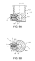
- the means 18 are formed by a rod 20 ( Figure 5B ) provided at a first longitudinal end with a head 22 intended to apply a force on the blade 14.
- the plug 4 has a longitudinal through bore 24 ( Figure 5A ) in which is mounted the rod 20.
- the rod 20 is slidable in the bore 24.
- An axial retaining means 26 is mounted on the second longitudinal end of the rod 20 preventing it from escaping from the bore. bore 24.
- the head 22 is located inside the housing 2.
- the axial force is generated by an elastic means 30 mounted in reaction between the head 22 and the cover 4.
- it is a helical spring.
- the sliding mounting of the rod 20 in the cover 4 reduces the risk of damage to the blade 14.
- this assembly allows easy control of the force applied to the blade 14. The force can be tared so that the seal is assured, while allowing the quartz to vibrate freely. It suffices to constrain more or less the spring via the length between the head 22 and the bottom of part 4.1 of the cap.
- the head 22 can come into direct contact with the blade 14 or via an element interposed between the head 22 and the blade 14.
- the quartz in the case of a quartz microbalance, the quartz must be maintained, however, do not interfere with the vibrations of the quartz which make it possible to detect the variations of mass.
- an annular interposition element 28 bearing only on the outer edge of the quartz, allowing its maintenance without impeding its setting vibration.
- the flexible member 28 is an O-ring similar to the O-ring 16, allowing the use of a reduced number of different components.
- the quartz is held between two flexible elements formed by joints, the quartz is free to vibrate, it achieves greater accuracy in the measurements.
- the head 22 has on its face intended to be oriented towards the blade 14 a projecting central portion 22.1 ( Figure 5B ) of diameter slightly greater than that of the seal 28 allowing simple mounting and immobilization of the seal 28 on the head 22.
- the force exerted by the spring 30 is adapted to maintain the quartz plated against the O-ring 16 while allowing the quartz to vibrate at its resonant frequency.
- the spring force is between 2N and 3N. It is also easy to change the load of the spring depending on the size of the quartz playing on the length of the 20.
- a cover 32 is provided for covering the retaining means and ensuring the seal at the bore of the stopper 4.
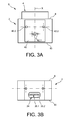
- the housing also includes a lateral passage 34 visible on the Figures 1, 2 , 3B and 4 for the mounting of the quartz blade 14, this passage 34 comprises a first portion of smaller section 35.1 corresponding to that of the quartz plate and metallizations, and a second portion of larger section 35.2.
- the blade 14 comprises a quartz plate 36 provided on its two faces with a metallization 38.1, 38.2 connected to pins 39.1, 39.2 intended to be connected to an external processing unit (not shown) and making it possible to measure the resonance variations of the quartz used to determine the change in mass.
- a transverse portion 40 connects the two pins 39.1, 39.2, whose shape cooperates with the shape of the portion of larger section 35.2 of the lateral passage 34, this transverse portion 40 closes the lateral passage 34
- the holding plate 42 ( figure 3A ) fixed on the support side of the side passage 34 and immobilizing the sensor.
- the holding plate 42 has two holes 42.1 for the pins 39.1, 39.2, two holes 42.2 for the passage of screws for fixing the plate on the support.
- the housing has corresponding holes for the fixing screws.
- the support S is for example made of Teflon®. It can be made of any other material. Teflon® has the advantage of being inert with respect to many chemical substances that can be used when using the microbalance, for example, inert with hydrofluoric acid.
- the support equipped with a quartz slide then forms a microbalance.
- the microbalance according to the present invention can be used in a gaseous medium, for example in air, in a liquid medium, or in a liquid medium coupled to electrochemical techniques. In the latter case, the microbalance is coupled to an electrochemical cell
- the support S forming a microbalance can therefore be used with an electrochemical cell filled with chemical substances serving as electrolyte.
- the support according to the present invention can be used with an electrochemical cell of the state of the art. Such a cell is represented on the figure 12 .
- Cell 100 of the state of the art comprises a container 102 of substantially cylindrical shape open at its upper end for the introduction of substances forming the electrochemical bath.
- the cell also comprises at a lower portion a neck 104 extending laterally for fixing the microbalance, more particularly the support S (not shown).
- the electrochemical solution fills the neck 104 and enters in contact with the blade 14.
- the neck 104 terminates in a flange 106 against which the support supports the plane, a seal is interposed between the collar 106 and the quartz support S.
- the support S is secured to the neck 104 by means of two clamps (not shown) connected by threaded rods, the flanges enclosing the neck collar and a collar of the support.
- This type of cell has several disadvantages.
- the cell is generally made of glass, so it is fragile, especially at the relatively long neck. In addition, tightening at the neck often causes breaks in the neck. On the other hand, fixing the support on the neck is laborious. And finally, the long neck forms a cavity in which gas bubbles can be trapped and distort the measurements.
- the cell comprises at the location of the outer face from which the collar exits, a flat surface forming a flat support face for the support.
- the fixation is effected either by tightening the collar flange but by tightening the cell body.
- the fixation is effected either by tightening the collar flange but by tightening the cell body.
- the cell has a side wall 48 and a bottom 49 forming a container for the electrochemical bath, the side wall 48 has a generally cylindrical shape with a constant outside diameter. According to the invention, the side wall 48 has a flat 50 at its lower part in which is formed a lateral orifice 52 for the introduction of the sensor and the contact with the bath. The face 10 of the support bears flat on the flat part 50. A seal (not shown) is interposed between the support and the cell
- Two clamps are provided 54.1, 54.2 enclosing the support and the body, threaded rods 55 connect the two flanges 54.1, 54.2.
- a flange 57 is provided on the support S cooperating with the flange 54.2 ensuring the centering of the support.
- the thickness e of the side wall 48 of the cell 44 is chosen as low as possible in order to minimize the size of the cavity that is formed by the lateral orifice 52. This thickness is chosen sufficiently thick to withstand the compressive force produced by the threaded rods by means of the flanges.
- the face 10 of the support S has a projecting edge 56 surrounding the access window to the blade, this edge 56 is itself surrounded by a flat surface recessed.
- the protrusion has outer dimensions slightly greater than the inner dimensions of the lateral orifice.
- the projection 56 is forcibly mounted in the lateral orifice 52 and the surrounding flat surface bears against the flat 50. This assembly ensures the maintenance of the support on the cell and the sealing of the connection. This arrangement advantageously avoids the use of clamps.
- FIG. 9A and 9B an exemplary embodiment of a cell can be seen in the case where small volumes are used.
- the cell body has a lower portion 44.2 of small inner diameter, the depth of the flat 50 being adapted to keep the distance between the bath and the sensor as small as possible.
- the cell according to the present invention has the advantage of allowing simple mounting of the support and therefore easy realization of a quartz microbalance.
- the electrochemical cell is advantageously made of Teflon®, making it suitable for use with a large number of substances. Moreover, she is not fragile.
- Teflon® makes the realization of the flat very easy, by machining or directly during molding.
- the cell of Figures 7A to 9B according to the present invention can be used with a quartz support of the state of the art.
- the support of the figure 2 has the advantage of allowing a quick and easy replacement of the quartz blade.
- the quartz blade requires precise positioning which is easily achieved by the present invention.
- a support S 'according to the present invention used as a sample holder.
- the support S 'according to the present invention is particularly suitable for such an application since it offers an overall seal, ie at the level of the front face at the level of the window and at the level of the rear face closed by the plug.
- the carrier according to the present invention can be fully immersed in a solution.
- the blade 14 is formed by a substrate, for example silicon on which is deposited a film forming the sample to be analyzed.
- This film is an electrically conductive or semiconductor material.
- the blade 14 is much less fragile than in the case of the quartz microbalance.
- the blade 14 then has the form of a tablet and has no pins.
- the blade 14 is then introduced directly into the passage 6 on the side 8 of the support S 'and comes to rest on the shoulder 12. Therefore, the support S' does not require lateral passage for the introduction of the sample, this which reduces the risk of liquid entering the sample holder.
- the support S ' has a passage for electrical son but they do not require disassembly, the seal is easily achievable.
- the support S ' has an electrical contact 58 intended to come into contact with the sample to measure the charge transfer between the sample and the liquid.
- the electrical contact 58 is provided on the shoulder 12. Consequently, the blade rests on the electrical contact 58, more particularly the face bearing the sample bears against the electrical contact 58.
- the electrical contact is for example made by means of a copper washer connected by a conductive wire to a processing unit.
- the electrical contact 58 is formed by a washer whose inner contour is cut so as to form tabs 60.
- the tabs 60 are slightly folded so as to form a truncated cone, thus the electrical contact between the sample and the tabs is improved, the tongues 60 thus configured forming a spring.
- the thickness of the tongues 60 is chosen as a function of the force transmitted by the spring 30.
- the number of tongues depends on the working surface, ie on the surface of the working window. By way of example only, for a sample of 1 cm 2 , 8 tongues of 80 ⁇ m in thickness are provided.
- a seal 16 is provided between the sample and the shoulder 12 to seal the sample holder vis-à-vis the solution.
- the seal 16 may be formed by an O-ring insert, or by a bead projecting from the shoulder 12. This latter embodiment simplifies assembly, the risk of forgetting the seal or a defective seal is removed.
- the electrical contact 58 is connected to wires 59 for transmitting the harvested electrical information to the sample-liquid interface.
- the sample holder is configured in the form of a rod, the support extending laterally by a hollow rod 62 in which runs the electric wire.
- the hollow rod is sealingly connected to the support S '. This rod can be dipped directly into a solution, so its manipulation is facilitated.
- the device for holding the blade 14 is similar to that described for the microbalance.
- the O-ring 28 can be omitted, the head 22 being able to press directly on the blade by a spherical surface allowing an equal distribution of the forces on the joint, more particularly on the substrate, since it is not the vibrations that the we want to measure in this case.
- the blade is much less fragile.
- This sample holder has the advantage, compared to the sample holders of the state of the art, of ensuring electrical contact directly with the sample to be analyzed, ie the film deposited on the substrate, which makes it possible to limit loss of information. On the contrary, in the sample holders of the state of the art, the electrical contact is made on the rear face of the substrate, there is then a loss of information through the substrate.
- the sample holder can also be used with an electrochemical cell of the state of the art or as previously described and represented on the Figures 7A, 7B , 8A, 8B , 9A and 9B .
- the support according to the present invention can be attached to a plate on which other elements would be fixed.
Landscapes
- Physics & Mathematics (AREA)
- General Physics & Mathematics (AREA)
- Sampling And Sample Adjustment (AREA)
- Investigating Or Analyzing Materials Using Thermal Means (AREA)
- Apparatus Associated With Microorganisms And Enzymes (AREA)
- Analysing Materials By The Use Of Radiation (AREA)
Applications Claiming Priority (1)
| Application Number | Priority Date | Filing Date | Title |
|---|---|---|---|
| FR0955269A FR2948761B1 (fr) | 2009-07-28 | 2009-07-28 | Support pour element mince, microbalance a quartz comportant un tel support et porte-echantillon comportant un tel support |
Publications (2)
| Publication Number | Publication Date |
|---|---|
| EP2280254A1 true EP2280254A1 (de) | 2011-02-02 |
| EP2280254B1 EP2280254B1 (de) | 2012-02-15 |
Family
ID=42109876
Family Applications (1)
| Application Number | Title | Priority Date | Filing Date |
|---|---|---|---|
| EP10170625A Not-in-force EP2280254B1 (de) | 2009-07-28 | 2010-07-23 | Halterung für ein dünnes Element, eine Quarzmikrowaage, die eine solche Halterung umfasst und ein Probenträger, der eine solche Halterung umfasst |
Country Status (4)
| Country | Link |
|---|---|
| US (1) | US8695403B2 (de) |
| EP (1) | EP2280254B1 (de) |
| AT (1) | ATE545849T1 (de) |
| FR (1) | FR2948761B1 (de) |
Families Citing this family (3)
| Publication number | Priority date | Publication date | Assignee | Title |
|---|---|---|---|---|
| US9426657B2 (en) | 2014-08-15 | 2016-08-23 | Facebook, Inc. | Bluetooth transmission security pattern |
| US9667352B2 (en) | 2015-01-09 | 2017-05-30 | Facebook, Inc. | Ultrasonic communications for wireless beacons |
| JP6879858B2 (ja) * | 2017-07-31 | 2021-06-02 | アズビル株式会社 | 熱式流量計 |
Citations (3)
| Publication number | Priority date | Publication date | Assignee | Title |
|---|---|---|---|---|
| JPS604819A (ja) * | 1983-06-23 | 1985-01-11 | Fuji Elelctrochem Co Ltd | 液面センサ− |
| GB2348286A (en) * | 1999-03-23 | 2000-09-27 | Atotech Deutschland Gmbh | Mounting for a quartz crystal |
| WO2001063224A1 (fr) * | 2000-02-23 | 2001-08-30 | Universite Pierre Et Marie Curie (Paris 6) | Microbalance a materiau piezoelectrique en milieu liquide |
Family Cites Families (4)
| Publication number | Priority date | Publication date | Assignee | Title |
|---|---|---|---|---|
| US4917499A (en) * | 1986-10-03 | 1990-04-17 | Hughes Aircraft Company | Apparatus for analyzing contamination |
| US6942782B2 (en) * | 2000-03-07 | 2005-09-13 | Nalco Company | Method and apparatus for measuring deposit forming capacity of fluids using an electrochemically controlled pH change in the fluid proximate to a piezoelectric microbalance |
| DE10011562C2 (de) * | 2000-03-09 | 2003-05-22 | Daimler Chrysler Ag | Gassensor |
| US7232545B2 (en) * | 2003-09-16 | 2007-06-19 | Steris Inc. | Sensor for determining concentration of fluid sterilant |
-
2009
- 2009-07-28 FR FR0955269A patent/FR2948761B1/fr not_active Expired - Fee Related
-
2010
- 2010-07-23 EP EP10170625A patent/EP2280254B1/de not_active Not-in-force
- 2010-07-23 US US12/842,969 patent/US8695403B2/en not_active Expired - Fee Related
- 2010-07-23 AT AT10170625T patent/ATE545849T1/de active
Patent Citations (3)
| Publication number | Priority date | Publication date | Assignee | Title |
|---|---|---|---|---|
| JPS604819A (ja) * | 1983-06-23 | 1985-01-11 | Fuji Elelctrochem Co Ltd | 液面センサ− |
| GB2348286A (en) * | 1999-03-23 | 2000-09-27 | Atotech Deutschland Gmbh | Mounting for a quartz crystal |
| WO2001063224A1 (fr) * | 2000-02-23 | 2001-08-30 | Universite Pierre Et Marie Curie (Paris 6) | Microbalance a materiau piezoelectrique en milieu liquide |
Also Published As
| Publication number | Publication date |
|---|---|
| FR2948761B1 (fr) | 2012-01-06 |
| ATE545849T1 (de) | 2012-03-15 |
| FR2948761A1 (fr) | 2011-02-04 |
| US8695403B2 (en) | 2014-04-15 |
| EP2280254B1 (de) | 2012-02-15 |
| US20110024291A1 (en) | 2011-02-03 |
Similar Documents
| Publication | Publication Date | Title |
|---|---|---|
| FR2591335A1 (fr) | Transducteur capacitif pour hautes pressions | |
| EP2280254B1 (de) | Halterung für ein dünnes Element, eine Quarzmikrowaage, die eine solche Halterung umfasst und ein Probenträger, der eine solche Halterung umfasst | |
| CH639762A5 (fr) | Transducteur de pression a element vibrant. | |
| FR2996011A1 (fr) | Procede de connexion d'une fibre optique et connecteur pour fibre optique | |
| EP1802911B1 (de) | Kryostat zum untersuchen von proben in einem vakuum | |
| EP3074749B1 (de) | Probenhalter und zugehörige permeationsvorrichtung | |
| FR2524654A1 (fr) | Dispositif de raccordement de fibres optiques et procede le mettant en oeuvre | |
| FR2769100A1 (fr) | Boitier pour dispositif photosemi-conducteur | |
| FR2571154A1 (fr) | Procede de fabrication d'un composant d'extremite pour fibre optique, et composant ainsi obtenu | |
| FR2948767A1 (fr) | Cellule electrochimique et ensemble de mesure comportant une telle cellule | |
| FR2748183A1 (fr) | Hydrophone et procede pour sa fabrication | |
| WO2000049440A1 (fr) | Connecteur optique perfectionne, destine en particulier a operer dans un environnement de haute pression | |
| CH709550A1 (fr) | Capteur de pression différentielle. | |
| EP1824779A1 (de) | Vorrichtung und verfahren zur hermetischen abdichtung eines hohlraums in einem elektronischen bauteil | |
| WO2020120598A1 (fr) | Capteur micro-onde du type à micro-ruban | |
| EP3166712A1 (de) | Basis eines moduls zur aufnahme eines in einer flüssigkeit gelösten gases und messvorrichtung | |
| FR3094068A1 (fr) | Réservoir pour gaz sous pression | |
| EP4147780A1 (de) | Mikrofluidische komponente, die zur messung der elektrischen impedanz durch ein biologisches objekt verwendet wird | |
| EP2605029B1 (de) | Probenhalter für ein Magnetometer | |
| FR3010788A1 (fr) | Cuve de mesure pour appareil de mesure spectrometrie | |
| WO2021123322A1 (fr) | Capteur de gaz | |
| FR3019650A1 (fr) | Dispositif de detection et/ou de dosage d'au moins un compose chimique et enceinte destinee a former un tel dispositif | |
| FR3016808A1 (fr) | Module de captage d'un gaz dissous dans un liquide et dispositif de mesure | |
| FR2963741A1 (fr) | Dispositif de maintien par capillarite d'un element comportant au moins une face plane | |
| EP0541438A1 (de) | Vorrichtung zum Messen der Temperatur einer Probe |
Legal Events
| Date | Code | Title | Description |
|---|---|---|---|
| PUAI | Public reference made under article 153(3) epc to a published international application that has entered the european phase |
Free format text: ORIGINAL CODE: 0009012 |
|
| AK | Designated contracting states |
Kind code of ref document: A1 Designated state(s): AL AT BE BG CH CY CZ DE DK EE ES FI FR GB GR HR HU IE IS IT LI LT LU LV MC MK MT NL NO PL PT RO SE SI SK SM TR |
|
| AX | Request for extension of the european patent |
Extension state: BA ME RS |
|
| 17P | Request for examination filed |
Effective date: 20110719 |
|
| GRAP | Despatch of communication of intention to grant a patent |
Free format text: ORIGINAL CODE: EPIDOSNIGR1 |
|
| GRAS | Grant fee paid |
Free format text: ORIGINAL CODE: EPIDOSNIGR3 |
|
| GRAA | (expected) grant |
Free format text: ORIGINAL CODE: 0009210 |
|
| AK | Designated contracting states |
Kind code of ref document: B1 Designated state(s): AL AT BE BG CH CY CZ DE DK EE ES FI FR GB GR HR HU IE IS IT LI LT LU LV MC MK MT NL NO PL PT RO SE SI SK SM TR |
|
| REG | Reference to a national code |
Ref country code: CH Ref legal event code: EP Ref country code: GB Ref legal event code: FG4D Free format text: NOT ENGLISH |
|
| REG | Reference to a national code |
Ref country code: IE Ref legal event code: FG4D Free format text: LANGUAGE OF EP DOCUMENT: FRENCH |
|
| REG | Reference to a national code |
Ref country code: AT Ref legal event code: REF Ref document number: 545849 Country of ref document: AT Kind code of ref document: T Effective date: 20120315 |
|
| REG | Reference to a national code |
Ref country code: DE Ref legal event code: R096 Ref document number: 602010000857 Country of ref document: DE Effective date: 20120412 |
|
| REG | Reference to a national code |
Ref country code: NL Ref legal event code: VDEP Effective date: 20120215 |
|
| LTIE | Lt: invalidation of european patent or patent extension |
Effective date: 20120215 |
|
| PG25 | Lapsed in a contracting state [announced via postgrant information from national office to epo] |
Ref country code: IS Free format text: LAPSE BECAUSE OF FAILURE TO SUBMIT A TRANSLATION OF THE DESCRIPTION OR TO PAY THE FEE WITHIN THE PRESCRIBED TIME-LIMIT Effective date: 20120615 Ref country code: LT Free format text: LAPSE BECAUSE OF FAILURE TO SUBMIT A TRANSLATION OF THE DESCRIPTION OR TO PAY THE FEE WITHIN THE PRESCRIBED TIME-LIMIT Effective date: 20120215 Ref country code: NL Free format text: LAPSE BECAUSE OF FAILURE TO SUBMIT A TRANSLATION OF THE DESCRIPTION OR TO PAY THE FEE WITHIN THE PRESCRIBED TIME-LIMIT Effective date: 20120215 Ref country code: HR Free format text: LAPSE BECAUSE OF FAILURE TO SUBMIT A TRANSLATION OF THE DESCRIPTION OR TO PAY THE FEE WITHIN THE PRESCRIBED TIME-LIMIT Effective date: 20120215 Ref country code: NO Free format text: LAPSE BECAUSE OF FAILURE TO SUBMIT A TRANSLATION OF THE DESCRIPTION OR TO PAY THE FEE WITHIN THE PRESCRIBED TIME-LIMIT Effective date: 20120515 |
|
| PG25 | Lapsed in a contracting state [announced via postgrant information from national office to epo] |
Ref country code: PT Free format text: LAPSE BECAUSE OF FAILURE TO SUBMIT A TRANSLATION OF THE DESCRIPTION OR TO PAY THE FEE WITHIN THE PRESCRIBED TIME-LIMIT Effective date: 20120615 Ref country code: LV Free format text: LAPSE BECAUSE OF FAILURE TO SUBMIT A TRANSLATION OF THE DESCRIPTION OR TO PAY THE FEE WITHIN THE PRESCRIBED TIME-LIMIT Effective date: 20120215 Ref country code: FI Free format text: LAPSE BECAUSE OF FAILURE TO SUBMIT A TRANSLATION OF THE DESCRIPTION OR TO PAY THE FEE WITHIN THE PRESCRIBED TIME-LIMIT Effective date: 20120215 Ref country code: PL Free format text: LAPSE BECAUSE OF FAILURE TO SUBMIT A TRANSLATION OF THE DESCRIPTION OR TO PAY THE FEE WITHIN THE PRESCRIBED TIME-LIMIT Effective date: 20120215 Ref country code: GR Free format text: LAPSE BECAUSE OF FAILURE TO SUBMIT A TRANSLATION OF THE DESCRIPTION OR TO PAY THE FEE WITHIN THE PRESCRIBED TIME-LIMIT Effective date: 20120516 |
|
| REG | Reference to a national code |
Ref country code: IE Ref legal event code: FD4D |
|
| REG | Reference to a national code |
Ref country code: AT Ref legal event code: MK05 Ref document number: 545849 Country of ref document: AT Kind code of ref document: T Effective date: 20120215 |
|
| PG25 | Lapsed in a contracting state [announced via postgrant information from national office to epo] |
Ref country code: CY Free format text: LAPSE BECAUSE OF FAILURE TO SUBMIT A TRANSLATION OF THE DESCRIPTION OR TO PAY THE FEE WITHIN THE PRESCRIBED TIME-LIMIT Effective date: 20120215 |
|
| PG25 | Lapsed in a contracting state [announced via postgrant information from national office to epo] |
Ref country code: SI Free format text: LAPSE BECAUSE OF FAILURE TO SUBMIT A TRANSLATION OF THE DESCRIPTION OR TO PAY THE FEE WITHIN THE PRESCRIBED TIME-LIMIT Effective date: 20120215 Ref country code: CZ Free format text: LAPSE BECAUSE OF FAILURE TO SUBMIT A TRANSLATION OF THE DESCRIPTION OR TO PAY THE FEE WITHIN THE PRESCRIBED TIME-LIMIT Effective date: 20120215 Ref country code: SE Free format text: LAPSE BECAUSE OF FAILURE TO SUBMIT A TRANSLATION OF THE DESCRIPTION OR TO PAY THE FEE WITHIN THE PRESCRIBED TIME-LIMIT Effective date: 20120215 Ref country code: DK Free format text: LAPSE BECAUSE OF FAILURE TO SUBMIT A TRANSLATION OF THE DESCRIPTION OR TO PAY THE FEE WITHIN THE PRESCRIBED TIME-LIMIT Effective date: 20120215 Ref country code: EE Free format text: LAPSE BECAUSE OF FAILURE TO SUBMIT A TRANSLATION OF THE DESCRIPTION OR TO PAY THE FEE WITHIN THE PRESCRIBED TIME-LIMIT Effective date: 20120215 Ref country code: RO Free format text: LAPSE BECAUSE OF FAILURE TO SUBMIT A TRANSLATION OF THE DESCRIPTION OR TO PAY THE FEE WITHIN THE PRESCRIBED TIME-LIMIT Effective date: 20120215 Ref country code: IE Free format text: LAPSE BECAUSE OF FAILURE TO SUBMIT A TRANSLATION OF THE DESCRIPTION OR TO PAY THE FEE WITHIN THE PRESCRIBED TIME-LIMIT Effective date: 20120215 |
|
| PG25 | Lapsed in a contracting state [announced via postgrant information from national office to epo] |
Ref country code: IT Free format text: LAPSE BECAUSE OF FAILURE TO SUBMIT A TRANSLATION OF THE DESCRIPTION OR TO PAY THE FEE WITHIN THE PRESCRIBED TIME-LIMIT Effective date: 20120215 Ref country code: SK Free format text: LAPSE BECAUSE OF FAILURE TO SUBMIT A TRANSLATION OF THE DESCRIPTION OR TO PAY THE FEE WITHIN THE PRESCRIBED TIME-LIMIT Effective date: 20120215 |
|
| PLBE | No opposition filed within time limit |
Free format text: ORIGINAL CODE: 0009261 |
|
| STAA | Information on the status of an ep patent application or granted ep patent |
Free format text: STATUS: NO OPPOSITION FILED WITHIN TIME LIMIT |
|
| 26N | No opposition filed |
Effective date: 20121116 |
|
| BERE | Be: lapsed |
Owner name: COMMISSARIAT A L'ENERGIE ATOMIQUE ET AUX ENERGIES Effective date: 20120731 |
|
| PG25 | Lapsed in a contracting state [announced via postgrant information from national office to epo] |
Ref country code: AT Free format text: LAPSE BECAUSE OF FAILURE TO SUBMIT A TRANSLATION OF THE DESCRIPTION OR TO PAY THE FEE WITHIN THE PRESCRIBED TIME-LIMIT Effective date: 20120215 |
|
| PG25 | Lapsed in a contracting state [announced via postgrant information from national office to epo] |
Ref country code: MK Free format text: LAPSE BECAUSE OF FAILURE TO SUBMIT A TRANSLATION OF THE DESCRIPTION OR TO PAY THE FEE WITHIN THE PRESCRIBED TIME-LIMIT Effective date: 20120215 Ref country code: MC Free format text: LAPSE BECAUSE OF NON-PAYMENT OF DUE FEES Effective date: 20120731 |
|
| REG | Reference to a national code |
Ref country code: DE Ref legal event code: R097 Ref document number: 602010000857 Country of ref document: DE Effective date: 20121116 |
|
| PG25 | Lapsed in a contracting state [announced via postgrant information from national office to epo] |
Ref country code: ES Free format text: LAPSE BECAUSE OF FAILURE TO SUBMIT A TRANSLATION OF THE DESCRIPTION OR TO PAY THE FEE WITHIN THE PRESCRIBED TIME-LIMIT Effective date: 20120526 |
|
| PG25 | Lapsed in a contracting state [announced via postgrant information from national office to epo] |
Ref country code: BE Free format text: LAPSE BECAUSE OF NON-PAYMENT OF DUE FEES Effective date: 20120731 |
|
| PG25 | Lapsed in a contracting state [announced via postgrant information from national office to epo] |
Ref country code: BG Free format text: LAPSE BECAUSE OF FAILURE TO SUBMIT A TRANSLATION OF THE DESCRIPTION OR TO PAY THE FEE WITHIN THE PRESCRIBED TIME-LIMIT Effective date: 20120515 Ref country code: MT Free format text: LAPSE BECAUSE OF FAILURE TO SUBMIT A TRANSLATION OF THE DESCRIPTION OR TO PAY THE FEE WITHIN THE PRESCRIBED TIME-LIMIT Effective date: 20120215 |
|
| PG25 | Lapsed in a contracting state [announced via postgrant information from national office to epo] |
Ref country code: AL Free format text: LAPSE BECAUSE OF FAILURE TO SUBMIT A TRANSLATION OF THE DESCRIPTION OR TO PAY THE FEE WITHIN THE PRESCRIBED TIME-LIMIT Effective date: 20120215 |
|
| PG25 | Lapsed in a contracting state [announced via postgrant information from national office to epo] |
Ref country code: TR Free format text: LAPSE BECAUSE OF FAILURE TO SUBMIT A TRANSLATION OF THE DESCRIPTION OR TO PAY THE FEE WITHIN THE PRESCRIBED TIME-LIMIT Effective date: 20120215 |
|
| PG25 | Lapsed in a contracting state [announced via postgrant information from national office to epo] |
Ref country code: LU Free format text: LAPSE BECAUSE OF NON-PAYMENT OF DUE FEES Effective date: 20120723 Ref country code: SM Free format text: LAPSE BECAUSE OF FAILURE TO SUBMIT A TRANSLATION OF THE DESCRIPTION OR TO PAY THE FEE WITHIN THE PRESCRIBED TIME-LIMIT Effective date: 20120215 |
|
| PG25 | Lapsed in a contracting state [announced via postgrant information from national office to epo] |
Ref country code: HU Free format text: LAPSE BECAUSE OF FAILURE TO SUBMIT A TRANSLATION OF THE DESCRIPTION OR TO PAY THE FEE WITHIN THE PRESCRIBED TIME-LIMIT Effective date: 20100723 |
|
| REG | Reference to a national code |
Ref country code: CH Ref legal event code: PL |
|
| PG25 | Lapsed in a contracting state [announced via postgrant information from national office to epo] |
Ref country code: CH Free format text: LAPSE BECAUSE OF NON-PAYMENT OF DUE FEES Effective date: 20140731 Ref country code: LI Free format text: LAPSE BECAUSE OF NON-PAYMENT OF DUE FEES Effective date: 20140731 |
|
| REG | Reference to a national code |
Ref country code: FR Ref legal event code: PLFP Year of fee payment: 7 |
|
| REG | Reference to a national code |
Ref country code: FR Ref legal event code: PLFP Year of fee payment: 8 |
|
| REG | Reference to a national code |
Ref country code: FR Ref legal event code: PLFP Year of fee payment: 9 |
|
| PGFP | Annual fee paid to national office [announced via postgrant information from national office to epo] |
Ref country code: DE Payment date: 20180710 Year of fee payment: 9 Ref country code: FR Payment date: 20180727 Year of fee payment: 9 |
|
| PGFP | Annual fee paid to national office [announced via postgrant information from national office to epo] |
Ref country code: GB Payment date: 20180718 Year of fee payment: 9 |
|
| REG | Reference to a national code |
Ref country code: DE Ref legal event code: R119 Ref document number: 602010000857 Country of ref document: DE |
|
| GBPC | Gb: european patent ceased through non-payment of renewal fee |
Effective date: 20190723 |
|
| PG25 | Lapsed in a contracting state [announced via postgrant information from national office to epo] |
Ref country code: GB Free format text: LAPSE BECAUSE OF NON-PAYMENT OF DUE FEES Effective date: 20190723 Ref country code: DE Free format text: LAPSE BECAUSE OF NON-PAYMENT OF DUE FEES Effective date: 20200201 |
|
| PG25 | Lapsed in a contracting state [announced via postgrant information from national office to epo] |
Ref country code: FR Free format text: LAPSE BECAUSE OF NON-PAYMENT OF DUE FEES Effective date: 20190731 |