EP2279956A2 - A thin-wall, multi-layer packaging container with a barrier layer producing using injection moulding and method for producing same - Google Patents
A thin-wall, multi-layer packaging container with a barrier layer producing using injection moulding and method for producing same Download PDFInfo
- Publication number
- EP2279956A2 EP2279956A2 EP10007770A EP10007770A EP2279956A2 EP 2279956 A2 EP2279956 A2 EP 2279956A2 EP 10007770 A EP10007770 A EP 10007770A EP 10007770 A EP10007770 A EP 10007770A EP 2279956 A2 EP2279956 A2 EP 2279956A2
- Authority
- EP
- European Patent Office
- Prior art keywords
- packaging container
- layer
- thin
- inner layer
- walled
- Prior art date
- Legal status (The legal status is an assumption and is not a legal conclusion. Google has not performed a legal analysis and makes no representation as to the accuracy of the status listed.)
- Withdrawn
Links
Images


Classifications
-
- B—PERFORMING OPERATIONS; TRANSPORTING
- B65—CONVEYING; PACKING; STORING; HANDLING THIN OR FILAMENTARY MATERIAL
- B65D—CONTAINERS FOR STORAGE OR TRANSPORT OF ARTICLES OR MATERIALS, e.g. BAGS, BARRELS, BOTTLES, BOXES, CANS, CARTONS, CRATES, DRUMS, JARS, TANKS, HOPPERS, FORWARDING CONTAINERS; ACCESSORIES, CLOSURES, OR FITTINGS THEREFOR; PACKAGING ELEMENTS; PACKAGES
- B65D1/00—Containers having bodies formed in one piece, e.g. by casting metallic material, by moulding plastics, by blowing vitreous material, by throwing ceramic material, by moulding pulped fibrous material, by deep-drawing operations performed on sheet material
- B65D1/22—Boxes or like containers with side walls of substantial depth for enclosing contents
- B65D1/26—Thin-walled containers, e.g. formed by deep-drawing operations
- B65D1/28—Thin-walled containers, e.g. formed by deep-drawing operations formed of laminated material
-
- B—PERFORMING OPERATIONS; TRANSPORTING
- B29—WORKING OF PLASTICS; WORKING OF SUBSTANCES IN A PLASTIC STATE IN GENERAL
- B29C—SHAPING OR JOINING OF PLASTICS; SHAPING OF MATERIAL IN A PLASTIC STATE, NOT OTHERWISE PROVIDED FOR; AFTER-TREATMENT OF THE SHAPED PRODUCTS, e.g. REPAIRING
- B29C45/00—Injection moulding, i.e. forcing the required volume of moulding material through a nozzle into a closed mould; Apparatus therefor
- B29C45/16—Making multilayered or multicoloured articles
- B29C2045/167—Making multilayered or multicoloured articles injecting the second layer through the first layer
-
- B—PERFORMING OPERATIONS; TRANSPORTING
- B29—WORKING OF PLASTICS; WORKING OF SUBSTANCES IN A PLASTIC STATE IN GENERAL
- B29C—SHAPING OR JOINING OF PLASTICS; SHAPING OF MATERIAL IN A PLASTIC STATE, NOT OTHERWISE PROVIDED FOR; AFTER-TREATMENT OF THE SHAPED PRODUCTS, e.g. REPAIRING
- B29C45/00—Injection moulding, i.e. forcing the required volume of moulding material through a nozzle into a closed mould; Apparatus therefor
- B29C45/16—Making multilayered or multicoloured articles
- B29C45/1642—Making multilayered or multicoloured articles having a "sandwich" structure
-
- B—PERFORMING OPERATIONS; TRANSPORTING
- B29—WORKING OF PLASTICS; WORKING OF SUBSTANCES IN A PLASTIC STATE IN GENERAL
- B29K—INDEXING SCHEME ASSOCIATED WITH SUBCLASSES B29B, B29C OR B29D, RELATING TO MOULDING MATERIALS OR TO MATERIALS FOR MOULDS, REINFORCEMENTS, FILLERS OR PREFORMED PARTS, e.g. INSERTS
- B29K2995/00—Properties of moulding materials, reinforcements, fillers, preformed parts or moulds
- B29K2995/0037—Other properties
- B29K2995/0065—Permeability to gases
- B29K2995/0067—Permeability to gases non-permeable
Definitions
- the present invention relates to a thin-walled injection-molded multilayer packaging container with a barrier layer according to the preamble of claim 1 and to a method for producing such a packaging container having the features of the preamble of claim 9.
- the barrier layer prevents unwanted influences, such as light, oxygen and / or water vapor coming into contact with the product.
- unwanted influences such as light, oxygen and / or water vapor coming into contact with the product.
- the quality of the bottled product as long as possible remains unchanged. For example, contact with water vapor or oxygen can spoil the contents faster.
- Multilayer packaging containers with a barrier layer and methods for their production are known in many forms.
- multilayer packaging containers are produced by multilayer injection molding, lamination, thermoforming, in-mold labeling (IML), injection stretch blow molding, etc.
- the barrier layer is e.g. applied after injection molding of a Anspritzlings by lamination or after a pretreatment by spraying.
- the barrier layer is either on the outside of the package, whereby it can be easily damaged, or that it comes into contact with the contents, which may negatively affect the contents.
- the multi-stage production of multi-layer packaging containers is correspondingly expensive.
- a multilayer, multi-component plastic molded part is described by multilayer spraying.
- a preform is first produced by injection molding of a thermoplastic component. Subsequently, the preform is subjected to a plasma gas flow, and then sprayed with a crosslinking elastomer. This is to achieve a good and lasting connection between the two types of plastic.
- a container made of a polyolefin composition contains a metallic catalyst.
- the catalyst promotes oxidation of the polyolefins with oxygen, thereby lowering the oxygen permeability of the container.
- the outside and inside are overlaminated with a resin.
- the DE 102005045621 A1 describes a packaging container with high gas-tightness and a method for its preparation.
- the packaging container is manufactured by injection molding.
- a film, which is inserted into the mold and has a high gas-tightness, is back-injected according to the in-mold labeling method.
- the packaging container produced by this method achieves a high gas tightness in the area of the embedded film.
- the barrier layer which is arranged between the outside and inside of a thick-walled preform, consists of a mixture of the plastic material of the outside and / or inside and of a barrier material.
- the preform is transferred in a second process step by blowing into the hollow body having the desired shape.
- the invention solves the problem of providing a thin-walled injection-molded multilayer packaging container and a method of producing the same, which are simpler and less expensive than the prior art.
- the invention provides an injection-molded multilayer packaging container having the features of claim 1 and a manufacturing method having the features of claim 9.
- the container wall consists of at least three layers.
- a self-contained inner layer is completely enclosed by the outer layer.
- the outer layer is located on both sides of the inner layer and consists in its two parts of the same thermoplastic.
- the inner layer lying between these subregions consists of a substance with a higher barrier property than the outer layer.
- the multilayer packaging container can be produced by the coinjection method.
- the barrier layer material is injected into the so-called hot core between the thermoplastic resin material of the outer layer. It thus usually occurs at no point through the outer layer.
- thermoplastic material in principle, any thermoplastic material can be used. However, preferably polypropylene (PP), polyethylene (PE), polystyrene (PS), polyethylene terephthalate (PET), polycarbonate (PC), polyvinyl chloride (PVC) or mixtures of said plastic materials are used.
- PP polypropylene
- PE polyethylene
- PS polystyrene
- PET polyethylene terephthalate
- PC polycarbonate
- PVC polyvinyl chloride
- the barrier layer is used - as mentioned above - to keep certain substances or other harmful influences that can penetrate through the outer layer of the contents or of the ambient atmosphere.
- the barrier layer ensures that light, in particular UV radiation, can not reach the product when the product is light-sensitive. It is also possible that the barrier layer prevents or at least reduces the penetration of water vapor in order to protect the filling material from drying out and weight loss, or from moisture absorption when it is a dry product. In many cases, it is particularly important to protect against the ingress of oxygen since the oxygen can react with the product. As a result, the contents are oxidized and may possibly discolor or, in the worst case, spoil faster. It is also possible to protect the contents of several of these or other different influences.
- barrier layer material ethylvinyl alcohol (EVOH), polyamide (PA), polyethylene terephthalate (PET), thermoplastic elastomers (TPE) or mixtures of the materials mentioned.
- EVOH ethylvinyl alcohol
- PA polyamide
- PET polyethylene terephthalate
- TPE thermoplastic elastomers
- the thinness of a packaging container according to the present invention is defined by the wall thickness / flow path ratio (WFV). Products that are thin-walled and have a WFV of less than 1: 100 are considered here.
- the present invention preferably prefers a WFV of less than 1: 150.
- the layer thickness of the inner layer is preferably between 0.02 and 0.3 mm.
- the inner layer makes up 5 to 30%, preferably 12 to 18%, of the packaging material thickness.
- the position of the inner layer with respect to the thickness of the container wall is basically freely selectable. It is especially asymmetrical.
- the inner layer on the outside of the container may be covered with a layer thickness of the outer layer of from 2 to 50% of the packaging material thickness or wall thickness, if the starting point of the injection mold lies inside the container.
- the inner layer on the inside of the container with a layer thickness of the outer layer of 2 to 50% of the packaging material thickness or Wall thickness to be covered when the gate of the injection mold on the outside of the container.
- the processing temperatures at the sprue point are between 150 and 300 ° C, depending on the material used.
- the mold which consists of at least one core and one die, is cooled to accelerate the hardening of the plastic.
- the invention prefers asymmetric cooling. 50 to 90% preferably about 80% of the cooling take place on the one and 10 to 50%, preferably about 20% of the cooling takes place on the other side of the packaging container.
- the core cooling is preferably stronger than the die cooling.
- One of the advantages of the invention is that the combination of a single-stage molding process by injection molding and the simultaneous insertion of a barrier layer creates a cost-effective product, which in contrast, for example to deep-drawing or aluminum packaging, has the advantage that u.a. a defined and optimized wall thickness, a high degree of reproducibility and high freedom of shaping can be achieved.
- the added benefit of an integrated barrier layer is achieved directly, without the wall thickness of the packaging container having to be reduced to the specified dimension in an independent and, moreover, less precise executable method step, such as stretch blow molding.
- an adhesive or release agent may be added to the material of the inner and / or preferably the outer layer as a component.
- a release agent is needed when there is a risk of possibly undesirable mixing between the outer and inner layers.
- An adhesive can be used to achieve better adhesion between the outer and inner layers, thus reducing the risk of delamination.
- the melt of the inner layer is injected into the plastic core of the outer layer forming in the injection mold.
- multi-chamber injection nozzles with so-called needle closures are available, such as in the WO99 / 22926 described.
- the inner layer is injected via a transverse layer controllable by a radially inner needle, and from the outer layer both partial layers or regions are injected via a cross section which can be controlled by a radially outer needle.
- injection molding without further deformation of the packaging container consists of a cast and the inner layer is embedded in the outer layer. The melts of the outer and inner layers are first joined together in the area of the needle closures.
- the two melts are fed through separate channels to close to or directly to the starting point of the packaging container.
- the processing temperature at the gate point is between 150 ° C and 300 ° C, depending on the material used.
- the needle guide system has 4 operating positions.
- the injection time is usually between 0.1 and 1 second. However, an injection time between 0.2 and 0.8 seconds is preferred.
- the injection mold is cooled in the cavity area by means of water cooling to temperatures well below the solidification temperatures of the material used for the outer layer, the core cooling being about 80% and the die cooling about 20% of the cooling capacity.
- Figures 1A to 1D show by way of example an injection-molded thin-walled multilayer packaging container 10.
- An inner layer 2 (FIG. Figures 1C to 1D ) is completely enveloped by the outer layer 1 A, B ( Fig. 1D ).
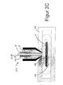
- FIGS. 2A to 2D By way of example, a coinjection sequence is illustrated in which only two materials are used. One skilled in the art can readily extend the illustrated embodiment to three or more materials.
- FIG. 2A the first operating position of the needle guide system 22 for producing a packaging container 10 is shown. Only the melt A of the outer layer 1A, B is injected into an injection mold 20. For the melt B of the inner layer 2 access to the mold 20 is initially denied.
- FIG. 2B the second operating position of the needle guide system 22 for the production of the packaging container 10 is shown. In this position, the melt A of the outer layer 1 A, B and the melt B of the inner layer both flow into the injection mold 20.
- melt of the inner layer 2 is guided into the plastic core 30 of the melt of the outer layer 1 A, B, after which it is displaced.
- Figure 2C is the third operating position of the needle guide system for the production shown. In this position, the melt of the inner layer 2 is again denied access to the injection mold 20. So that only the melt of the outer layer can continue to flow into the injection mold 20.
- FIG. 2D is the fourth operating position of the needle guide system shown. In this position, both the melt of the outer layer and the melt of the inner layer of access to the injection mold 20 is denied. In this operating position, the injection process is completed. The fact that the melt of the inner layer is guided through the melt of the outer layer, it can be seen that after complete filling of the injection mold 20, the inner layer 2 at any point of the outer layer 1 A, B of the packaging container 10 exits.
Abstract
Description
Die vorliegende Erfindung betrifft einen dünnwandigen spritzgegossenen mehrschichtigen Verpackungsbehälter mit einer Barriereschicht nach dem Oberbegriff von Anspruch 1 und ein Verfahren zum Herstellen eines solchen Verpackungsbehälters mit den Merkmalen des Oberbegriffs des Anspruchs 9.The present invention relates to a thin-walled injection-molded multilayer packaging container with a barrier layer according to the preamble of claim 1 and to a method for producing such a packaging container having the features of the preamble of claim 9.
Die Barriereschicht verhindert, dass unerwünschte Einflüsse, wie zum Beispiel Licht-, Sauerstoff- und/oder Wasserdampf, mit dem Füllgut in Kontakt kommen. Insbesondere beim Verpacken und Lagern von Lebensmitteln und Tiernahrung besteht die Anforderung, dass die Qualität des abgefüllten Produktes so lange wie möglich unverändert bleibt. So kann zum Beispiel der Kontakt mit Wasserdampf oder Sauerstoff das Füllgut schneller verderben lassen.The barrier layer prevents unwanted influences, such as light, oxygen and / or water vapor coming into contact with the product. In particular, in the packaging and storage of food and pet food, there is a requirement that the quality of the bottled product as long as possible remains unchanged. For example, contact with water vapor or oxygen can spoil the contents faster.
Es ist daher ein wichtiges Ziel in der Verpackungsindustrie die Barriereeigenschaften von Verpackungsbehältern zu verbessern und die Verpackungsbehälter auf einfache Weise kostengünstig herzustellen.It is therefore an important goal in the packaging industry to improve the barrier properties of packaging containers and to manufacture the packaging containers in a simple and cost-effective manner.
Mehrschichtige Verpackungsbehälter mit einer Barriereschicht und Verfahren zu deren Herstellung sind in vielfältiger Form bekannt. So werden zum Beispiel mehrschichtige Verpackungsbehälter durch mehrschichtiges Spritzgießen, Laminieren, Tiefziehen, In-Mold-Labeling (IML), Spritz-Reck-Blas-Verfahren, usw. hergestellt.Multilayer packaging containers with a barrier layer and methods for their production are known in many forms. For example, multilayer packaging containers are produced by multilayer injection molding, lamination, thermoforming, in-mold labeling (IML), injection stretch blow molding, etc.
Derzeit besteht bei mehrschichtigen Verpackungsbehältern das Problem, dass eine mehr oder minder lückenlose Barriereschicht nicht in einem einstufigen Produktionsverfahren erzielt werden kann. Vielmehr wird die Barriereschicht z.B. nach dem Spritzgießen eines Anspritzlings durch Auflaminieren oder nach einer Vorbehandlung durch Anspritzen aufgetragen. Dies hat jedoch den Nachteil, dass die Barriereschicht entweder auf der Außenseite der Verpackung liegt, wodurch sie einfach beschädigt werden kann, oder dass sie mit dem Füllgut in Berührung kommt, was unter Umständen das Füllgut negativ beeinflusst. Die mehrstufige Herstellung mehrschichtiger Verpackungsbehälter ist entsprechend kostenintensiv.Currently, in the case of multi-layered packaging containers, there is the problem that a more or less continuous barrier layer can not be achieved in a single-stage production process. Rather, the barrier layer is e.g. applied after injection molding of a Anspritzlings by lamination or after a pretreatment by spraying. However, this has the disadvantage that the barrier layer is either on the outside of the package, whereby it can be easily damaged, or that it comes into contact with the contents, which may negatively affect the contents. The multi-stage production of multi-layer packaging containers is correspondingly expensive.
In der
Eine andere Möglichkeit wird in
Die
In der
Eine andere Möglichkeit beschreibt die
Von dem oben genannten Stand der Technik ausgehend, löst die Erfindung das Problem, einen dünnwandigen spritzgegossenen mehrschichtigen Verpackungsbehälter und ein Verfahren zu dessen Herstellung zur Verfügung zu stellen, die gegenüber dem Stand der Technik vereinfacht und kostengünstiger sind.Starting from the above-mentioned prior art, the invention solves the problem of providing a thin-walled injection-molded multilayer packaging container and a method of producing the same, which are simpler and less expensive than the prior art.
Hierzu sieht die Erfindung einen spritzgegossenen mehrschichtigen Verpackungsbehälter mit den Merkmalen des Anspruchs 1 und ein Herstellungsverfahren mit den Merkmalen des Anspruchs 9 vor. Demgemäß besteht die Behälter-Wandung aus mindestens drei Schichten. Dabei wird eine in sich geschlossene Innenschicht von der Außenschicht vollständig umschlossen. Die Außenschicht befindet sich dabei auf beiden Seiten der Innenschicht und besteht in ihren beiden Teilbereichen aus demselben thermoplastischen Kunststoff. Die zwischen diesen Teilbereichen liegende Innenschicht besteht aus einem Stoff mit einer höheren Barriereeigenschaft als die Außenschicht.For this purpose, the invention provides an injection-molded multilayer packaging container having the features of claim 1 and a manufacturing method having the features of claim 9. Accordingly, the container wall consists of at least three layers. In this case, a self-contained inner layer is completely enclosed by the outer layer. The outer layer is located on both sides of the inner layer and consists in its two parts of the same thermoplastic. The inner layer lying between these subregions consists of a substance with a higher barrier property than the outer layer.
Der mehrschichtige Verpackungsbehälter kann im Koinjektionsverfahren hergestellt werden. Das Barriereschichtmaterial wird in die so genannte heiße Seele zwischen das thermoplastische Kunststoffmaterial der Außenschicht eingespritzt. Es tritt somit in der Regel an keiner Stelle durch die Außenschicht hindurch.The multilayer packaging container can be produced by the coinjection method. The barrier layer material is injected into the so-called hot core between the thermoplastic resin material of the outer layer. It thus usually occurs at no point through the outer layer.
Als Kunststoffmaterial ist prinzipiell jedes thermoplastische Material verwendbar. Jedoch werden bevorzugt Polypropylen (PP), Polyethylen (PE), Polystyrol (PS), Polyethylenterephthalat (PET), Polycarbonat (PC), Polyvinylchlorid (PVC) oder Mischungen der genannten Kunststoffmaterialien verwendet.As a plastic material, in principle, any thermoplastic material can be used. However, preferably polypropylene (PP), polyethylene (PE), polystyrene (PS), polyethylene terephthalate (PET), polycarbonate (PC), polyvinyl chloride (PVC) or mixtures of said plastic materials are used.
Die Barriereschicht dient - wie eingangs erwähnt - dazu, bestimmte Stoffe oder andere schädliche Einflüsse, die durch die Außenschicht dringen können, von dem Füllgut oder von der Umgebungsatmosphäre fernzuhalten. So sorgt die Barriereschicht zum Beispiel dafür, dass Licht, insbesondere UV-Strahlung, nicht an das Füllgut gelangen kann, wenn das Füllgut lichtsensitiv ist. Es ist auch möglich, dass die Barriereschicht Wasserdampfdurchtritt verhindert oder zumindest reduziert, um das Füllgut vor Austrocknung und Gewichtsverlust, oder vor Feuchtigkeitsaufnahme, wenn es sich um ein trockenes Füllgut handelt, zu schützen. Besonders wichtig ist in vielen Fällen, der Schutz vor Sauerstoffzutritt, da der Sauerstoff mit dem Füllgut reagieren kann. Dadurch wird das Füllgut oxidiert und kann sich möglicherweise verfärben oder schlimmstenfalls schneller verderben. Es ist auch möglich das Füllgut vor mehreren dieser oder vor anderen verschiedenen Einflüssen zu schützen. Dazu können mehrere und/oder Multifunktions-Barriereschichten zwischen die Außenschicht eingebracht werden. Als Barriereschichtmaterial ist prinzipiell jedes Material verwendbar, welches das Füllgut oder die Umgebungsatmosphäre vor schädlichen Einflüssen schützt, und/oder jeder Stoff mit einer höheren Barriereeigenschaft als die der Außenschicht. Für die Erfindung werden bevorzugt Ethylvinylalkohol (EVOH), Polyamid (PA), Polyethylenterephthalat (PET), Thermoplastische Elastomere (TPE) oder Mischungen der genannten Materialien verwendet.The barrier layer is used - as mentioned above - to keep certain substances or other harmful influences that can penetrate through the outer layer of the contents or of the ambient atmosphere. For example, the barrier layer ensures that light, in particular UV radiation, can not reach the product when the product is light-sensitive. It is also possible that the barrier layer prevents or at least reduces the penetration of water vapor in order to protect the filling material from drying out and weight loss, or from moisture absorption when it is a dry product. In many cases, it is particularly important to protect against the ingress of oxygen since the oxygen can react with the product. As a result, the contents are oxidized and may possibly discolor or, in the worst case, spoil faster. It is also possible to protect the contents of several of these or other different influences. For this purpose, multiple and / or multi-functional barrier layers can be introduced between the outer layer. In principle, any material which protects the filling material or the surrounding atmosphere from harmful influences, and / or any substance with a higher barrier property than that of the outer layer, can be used as the barrier layer material. For the invention, preference is given to using ethylvinyl alcohol (EVOH), polyamide (PA), polyethylene terephthalate (PET), thermoplastic elastomers (TPE) or mixtures of the materials mentioned.
Die Dünnwandigkeit eines Verpackungsbehälters im Sinne der vorliegenden Erfindung wird über das Wandstärken/Fließweg-Verhältnis (WFV) definiert. Dabei gelten Produkte als dünnwandig, die ein WFV kleiner als 1:100 besitzen. Die vorliegende Erfindung bevorzugt dabei ein WFV von kleiner als 1:150.The thinness of a packaging container according to the present invention is defined by the wall thickness / flow path ratio (WFV). Products that are thin-walled and have a WFV of less than 1: 100 are considered here. The present invention preferably prefers a WFV of less than 1: 150.
Bei Verpackungsbehältern gemäß der vorliegenden Erfindung beträgt die Schichtstärke der Innenschicht bevorzugt zwischen 0,02 und 0,3 mm. Dabei macht die Innenschicht 5 bis 30%, bevorzugt 12 bis 18%, der Verpackungsmaterialstärke aus.In packaging containers according to the present invention, the layer thickness of the inner layer is preferably between 0.02 and 0.3 mm. The inner layer makes up 5 to 30%, preferably 12 to 18%, of the packaging material thickness.
Die Lage der Innenschicht im Bezug auf die Dicke der Behälterwand ist grundsätzlich frei wählbar. Sie ist insbesondere asymmetrisch.The position of the inner layer with respect to the thickness of the container wall is basically freely selectable. It is especially asymmetrical.
Insbesondere kann die Innenschicht an der Behälteraußenseite mit einer Schichtstärke der Außenschicht von 2 bis 50% der Verpackungsmaterialstärke oder Wandungsdicke bedeckt sein, wenn der Angusspunkt der Spritzgießform im Behälterinneren liegt. Umgekehrt kann die Innenschicht an der Behälterinnenseite mit einer Schichtstärke der Außenschicht von 2 bis 50% der Verpackungsmaterialstärke oder Wandungsdicke bedeckt sein, wenn der Angusspunkt der Spritzgussform an der Behälteraußenseite liegt.In particular, the inner layer on the outside of the container may be covered with a layer thickness of the outer layer of from 2 to 50% of the packaging material thickness or wall thickness, if the starting point of the injection mold lies inside the container. Conversely, the inner layer on the inside of the container with a layer thickness of the outer layer of 2 to 50% of the packaging material thickness or Wall thickness to be covered when the gate of the injection mold on the outside of the container.
Die Verarbeitungstemperaturen am Angusspunkt betragen je nach verwendetem Material zwischen 150 und 300°C.The processing temperatures at the sprue point are between 150 and 300 ° C, depending on the material used.
Wie üblich beim Kunststoffspritzguss wird die Form, die zumindest aus einem Kern und einer Matrize besteht, gekühlt, um die Erhärtung des Kunststoffes zu beschleunigen. Die Erfindung bevorzugt eine asymmetrische Kühlung. 50 bis 90% vorzugsweise etwa 80% der Kühlung finden auf der einen und 10 bis 50% vorzugsweise etwa 20% der Kühlungen finden auf der anderen Verpackungsbehälterseite statt. Die Kernkühlung ist vorzugsweise stärker als die Matrizenkühlung.As usual in plastic injection molding, the mold, which consists of at least one core and one die, is cooled to accelerate the hardening of the plastic. The invention prefers asymmetric cooling. 50 to 90% preferably about 80% of the cooling take place on the one and 10 to 50%, preferably about 20% of the cooling takes place on the other side of the packaging container. The core cooling is preferably stronger than the die cooling.
Einer der Vorteile der Erfindung ist es, dass durch die Verknüpfung eines einstufigen Formgebungsprozesses durch Spritzgießen und dem gleichzeitigen Einfügen einer Barriereschicht ein kostengünstiges Produkt entsteht, welches im Gegensatz, etwa zum Tiefziehverfahren oder zu Alumniumverpackungen, den Vorteil besitzt, dass u.a. eine definierte und optimierte Wandstärke, ein hohes Maß an Reproduzierbarkeit und hohe Formgebungsfreiheit erreicht werden. Gleichzeitig wird der Zusatznutzen einer integrierten Barriereschicht unmittelbar erreicht, ohne dass die Wandstärke des Verpackungsbehälters in einem unabhängigen und zudem weniger präzise ausführbaren Verfahrensschritt, wie dem Streckblasen, auf das Sollmaß reduziert werden muss.One of the advantages of the invention is that the combination of a single-stage molding process by injection molding and the simultaneous insertion of a barrier layer creates a cost-effective product, which in contrast, for example to deep-drawing or aluminum packaging, has the advantage that u.a. a defined and optimized wall thickness, a high degree of reproducibility and high freedom of shaping can be achieved. At the same time, the added benefit of an integrated barrier layer is achieved directly, without the wall thickness of the packaging container having to be reduced to the specified dimension in an independent and, moreover, less precise executable method step, such as stretch blow molding.
Je nach verwendetem Barrierematerial kann es hilfreich sein, wenn ein Haft- oder Trennmittel eingesetzt wird. Dieses kann dem Material der Innen- und/oder vorzugsweise der Außenschicht als Bestandteil beigemischt sein. Ein Trennmittel wird dann benötigt, wenn die Gefahr eines ggf. unerwünschten Vermischens zwischen der Außen- und Innenschicht besteht. Ein Haftmittel kann verwendet werden, um eine bessere Haftung zwischen Außen- und Innenschicht zu erreichen, damit wird das Delaminierungsrisiko vermindert.Depending on the barrier material used, it may be helpful to use an adhesive or release agent. This may be added to the material of the inner and / or preferably the outer layer as a component. A release agent is needed when there is a risk of possibly undesirable mixing between the outer and inner layers. An adhesive can be used to achieve better adhesion between the outer and inner layers, thus reducing the risk of delamination.
Beim Herstellen eines Verpackungsbehälters wird die Schmelze der Innenschicht in die sich in der Spritzgießform ausbildenden plastischen Seele der Außenschicht eingespritzt. Hierzu stehen Mehrkammer-Einspritzdüsen mit sogenannten Nadelverschlüssen zur Verfügung, wie u.a. in der
Die vorgenannten sowie die beanspruchten und in den Ausführungsbeispielen beschriebenen erfindungsgemäß zu verwendenden Bauteile unterliegen in ihrer Größe, Formgestaltung, Materialauswahl und technischen Konzeption keinen besonderen Ausnahmebedingungen, so dass die in dem Anwendungsgebiet bekannten Auswahlkriterien uneingeschränkt Anwendung finden können Weitere Einzelheiten, Merkmale und Vorteile des Gegenstandes der Erfindung ergeben sich aus den Unteransprüchen, sowie aus der nachfolgenden Beschreibung der zugehörigen Zeichnungen, in der - beispielhaft - ein Ausführungsbeispiel eines Verpackungsbehälters dargestellt ist. Auch einzelne Merkmale der Ansprüche oder der Ausführungsformen können mit anderen Merkmalen anderer Ansprüche und Ausführungsformen kombiniert werden.The above-mentioned and the claimed and described in the embodiments described components to be used in their size, shape design, material selection and technical design are not subject to any special conditions, so that the well-known in the field of application selection criteria can apply without restriction Further details, features and advantages of the subject matter of the invention will become apparent from the subclaims, as well as from the following description of the accompanying drawings, in which - by way of example - an embodiment of a packaging container is shown. Also, individual features of the claims or of the embodiments may be combined with other features of other claims and embodiments.
In der Zeichnung zeigen
-
Figur 1AFig. 1 B) ; -
Figur 1B -
Figur 1C von demselben Verpackungsbehälter eine Detailansicht des Angusspunktes nachFig. 1A ; -
Figur 1D von demselben Verpackungsbehälter eine weitere Vertikalschnittansicht (Schnitt entlang der Linie B-B gemäßFig. 1 B) stark vergrößert sowie -
Figuren 2A bis 2D
-
Figure 1A a packaging container in vertical section view (section AA according toFig. 1 B) ; -
FIG. 1B the same packaging container in plan view; -
Figure 1C from the same packaging container a detail view of the gate point afterFig. 1A ; -
FIG. 1D from the same packaging container a further vertical sectional view (section along the line BB according to FIGFig. 1 B) greatly enlarged as well -
FIGS. 2A to 2D a production sequence in section with Koinjektionsdüsen and injection mold as a schematic representation.
In den
In
- 1 A, B1 A, B
- Außenschichtouter layer
- 22
- Innenschichtinner layer
- 1010
- Verpackungsbehälterpackaging container
- 2020
- Spritzgießforminjection mold
- 2222
- NadelführungssystemNeedle guidance system
- 3030
- plastische Seeleplastic soul
- AA
- erste Schmelzefirst melt
- BB
- zweite Schmelzesecond melt
Claims (14)
dass die Innenschicht in die Außenschicht eingebettet ist,
dass die Innenschicht eine in sich geschlossene Schicht ist, die aus einem Stoff mit einer höheren Barriereeigenschaft als die Außenschicht besteht und
dass der Verpackungsbehälter aus einem einzigen Guss besteht, wodurch die endgültige Form und die Schichtbildung der Wand des Verpackungsbehälters in einem einzigen Spritzguss-Prozessschritt unmittelbar herstellbar sind.A thin-walled, multi-layer plastic packaging container produced by injection molding with a barrier layer, inter alia for food and pet food, consisting of an outer layer and an inner layer of different materials, characterized
that the inner layer is embedded in the outer layer,
that the inner layer is a self-contained layer, which consists of a substance with a higher barrier property than the outer layer and
that the packaging container consists of a single casting, whereby the final shape and the layer formation of the wall of the packaging container in a single injection molding process step are directly produced.
dadurch gekennzeichnet,
dass eine Schmelze für die Innenschicht in die sich in der Spritzgießform ausbildende plastische Seele der Schmelze der Außenschicht eingeführt wird, und
dass der Verpackungsbehälter aus einem einzigen Guss hergestellt wird, wodurch die endgültige Formgebung und die Schichtbildung des Verpackungsbehälters durch Spritzgießen in einem einzigen Produktionsschritt unmittelbar erfolgen.Method for producing a thin-walled, multilayer, multi-component packaging container made of plastic, by injection molding,
characterized,
that a melt for the inner layer is introduced into the forming in the injection mold plastic core of the melt of the outer layer, and
that the packaging container is produced from a single casting, whereby the final shaping and the layer formation of the packaging container by injection molding in a single production step take place directly.
Applications Claiming Priority (1)
| Application Number | Priority Date | Filing Date | Title |
|---|---|---|---|
| DE102009035058A DE102009035058A1 (en) | 2009-07-28 | 2009-07-28 | An injection molded thin-walled multilayer plastic packaging container having a barrier layer and method of making the same |
Publications (2)
| Publication Number | Publication Date |
|---|---|
| EP2279956A2 true EP2279956A2 (en) | 2011-02-02 |
| EP2279956A3 EP2279956A3 (en) | 2014-06-04 |
Family
ID=43016608
Family Applications (1)
| Application Number | Title | Priority Date | Filing Date |
|---|---|---|---|
| EP10007770.0A Withdrawn EP2279956A3 (en) | 2009-07-28 | 2010-07-27 | A thin-wall, multi-layer packaging container with a barrier layer producing using injection moulding and method for producing same |
Country Status (2)
| Country | Link |
|---|---|
| EP (1) | EP2279956A3 (en) |
| DE (1) | DE102009035058A1 (en) |
Cited By (2)
| Publication number | Priority date | Publication date | Assignee | Title |
|---|---|---|---|---|
| EP2554353A1 (en) * | 2011-08-05 | 2013-02-06 | Trisa Holding AG | Tooth brush and method for the manufacture of a tooth brush |
| EP2768652B1 (en) | 2011-10-21 | 2018-04-18 | Milacron LLC | Non-symmetric multiple layer injection molded containers, molds and methods |
Families Citing this family (2)
| Publication number | Priority date | Publication date | Assignee | Title |
|---|---|---|---|---|
| US20170008694A1 (en) | 2013-12-03 | 2017-01-12 | Biserkon Holdings Ltd. | Capsule and device for preparing beverages and method for producing the capsule |
| CA3016147A1 (en) | 2016-04-07 | 2017-10-12 | Nestec S.A. | Closed capsule with opening means and integral barrier layer |
Citations (6)
| Publication number | Priority date | Publication date | Assignee | Title |
|---|---|---|---|---|
| DE69130026T2 (en) | 1990-04-10 | 1999-03-18 | Toppan Printing Co Ltd | Containers made of polyolefin composition with limited oxygen permeability |
| WO1999022926A1 (en) | 1997-11-04 | 1999-05-14 | Otto Hofstetter Ag Werkzeug- Und Formenbau | Method for producing multi-layered preforms |
| DE10308742A1 (en) | 2003-02-28 | 2004-09-16 | Krauss-Maffei Kunststofftechnik Gmbh | Process for the production of multi-component molded plastic parts |
| DE102004054938A1 (en) | 2004-11-13 | 2006-05-18 | Grünwald, Heinrich, Dr. | Stretch blown or extrusion blown internal coated plastic container manufacture, involves pre-inflation with gas, followed by final inflation with ignited combustible gas containing substances to form barrier layer |
| DE102005018245A1 (en) | 2005-04-19 | 2006-10-26 | Mht Mold & Hotrunner Technology Ag | Multilayer preform, multilayer hollow body and process for their preparation |
| DE102005045621A1 (en) | 2005-09-23 | 2007-04-05 | Abro Weidenhammer Gmbh | Producing packaging containers by plasticating and injection molding a plastic material comprises introducing a gastight film into the mold before injecting the plastic material |
Family Cites Families (4)
| Publication number | Priority date | Publication date | Assignee | Title |
|---|---|---|---|---|
| JPH0985780A (en) * | 1995-09-22 | 1997-03-31 | Ube Ind Ltd | Method of deflected multi-layer molding |
| JPH1045169A (en) * | 1996-07-30 | 1998-02-17 | Polyplastics Co | Container for preserving food |
| ES2693703T3 (en) * | 2001-06-18 | 2018-12-13 | Becton, Dickinson And Company | Process to form multi-layer containers |
| JP2008307846A (en) * | 2007-06-18 | 2008-12-25 | Dainippon Printing Co Ltd | Coinjection-molded container and its manufacturing method |
-
2009
- 2009-07-28 DE DE102009035058A patent/DE102009035058A1/en not_active Withdrawn
-
2010
- 2010-07-27 EP EP10007770.0A patent/EP2279956A3/en not_active Withdrawn
Patent Citations (6)
| Publication number | Priority date | Publication date | Assignee | Title |
|---|---|---|---|---|
| DE69130026T2 (en) | 1990-04-10 | 1999-03-18 | Toppan Printing Co Ltd | Containers made of polyolefin composition with limited oxygen permeability |
| WO1999022926A1 (en) | 1997-11-04 | 1999-05-14 | Otto Hofstetter Ag Werkzeug- Und Formenbau | Method for producing multi-layered preforms |
| DE10308742A1 (en) | 2003-02-28 | 2004-09-16 | Krauss-Maffei Kunststofftechnik Gmbh | Process for the production of multi-component molded plastic parts |
| DE102004054938A1 (en) | 2004-11-13 | 2006-05-18 | Grünwald, Heinrich, Dr. | Stretch blown or extrusion blown internal coated plastic container manufacture, involves pre-inflation with gas, followed by final inflation with ignited combustible gas containing substances to form barrier layer |
| DE102005018245A1 (en) | 2005-04-19 | 2006-10-26 | Mht Mold & Hotrunner Technology Ag | Multilayer preform, multilayer hollow body and process for their preparation |
| DE102005045621A1 (en) | 2005-09-23 | 2007-04-05 | Abro Weidenhammer Gmbh | Producing packaging containers by plasticating and injection molding a plastic material comprises introducing a gastight film into the mold before injecting the plastic material |
Cited By (5)
| Publication number | Priority date | Publication date | Assignee | Title |
|---|---|---|---|---|
| EP2554353A1 (en) * | 2011-08-05 | 2013-02-06 | Trisa Holding AG | Tooth brush and method for the manufacture of a tooth brush |
| WO2013020237A1 (en) * | 2011-08-05 | 2013-02-14 | Trisa Holding Ag | Method for producing a toothbrush, and toothbrush |
| RU2611527C2 (en) * | 2011-08-05 | 2017-02-27 | Триза Хольдинг Аг | Method of toothbrush making and toothbrush |
| US11077592B2 (en) | 2011-08-05 | 2021-08-03 | Trisa Holding Ag | Method for producing a toothbrush, and toothbrush |
| EP2768652B1 (en) | 2011-10-21 | 2018-04-18 | Milacron LLC | Non-symmetric multiple layer injection molded containers, molds and methods |
Also Published As
| Publication number | Publication date |
|---|---|
| EP2279956A3 (en) | 2014-06-04 |
| DE102009035058A1 (en) | 2011-02-10 |
Similar Documents
| Publication | Publication Date | Title |
|---|---|---|
| DE60031828T2 (en) | Method for producing hollow bodies from plastic | |
| AU605654B2 (en) | Improved coextrusion blowmolding process | |
| DE69713689T3 (en) | Hot runner closure valve for avoiding one-sided molecular orientation and welding lines of solidified plastic, used for the production of moldings | |
| EP1894702A2 (en) | Method for manufacturing a fuel container and fuel container | |
| US20170043913A1 (en) | Container and method of forming the same | |
| DE3432959A1 (en) | METHOD AND DEVICE FOR PRODUCING A PLASTIC MOLDED BODY OBTAINED BY EXTRUSION AND HAVING A PREDICTED CROSS-SECTIONAL MOLD FROM A CELL-LIKE DOMESTICALLY DOMESTICALLY DOMESTICALLY DESTRUCTED, DOMESTICALLY-DEFECTED | |
| DE2742408A1 (en) | PLASTIC HOLLOW BODY AND METHOD FOR ITS MANUFACTURING | |
| EP2279956A2 (en) | A thin-wall, multi-layer packaging container with a barrier layer producing using injection moulding and method for producing same | |
| DE60203993T2 (en) | METHOD FOR PRODUCING A DIFFUSION-SEALED PLASTIC CONTAINER | |
| CH653601A5 (en) | PREFORMING MADE OF THERMOPLASTIC PLASTIC. | |
| WO2012147501A1 (en) | Preform injection molding device, injection molding method, and synthetic resin bottle body | |
| EP0907493B1 (en) | Plastic tube body and process for manufacturing the same | |
| DE102010036103B4 (en) | Multi-component injection molding process for the production of a sleeve-shaped preform and preform | |
| EP2334399B1 (en) | Method for manufacturing a filter end disc and a fluid filter, filter end disc | |
| DE102011100078A1 (en) | Method for manufacturing plastic container coated with plastic material for food product, involves providing film or film body in specific areas with reinforcement in regions, which are exposed to high mechanical load during molding process | |
| EP2934846A1 (en) | Method for producing a plastic molded part, and injection-molding machine | |
| DE102005037274A1 (en) | Method and device for the production of cylindrical shaped parts according to the method of in-mold labeling | |
| DE102004060009B4 (en) | Method for producing a laminated body | |
| DE2649526A1 (en) | PROCESS FOR MANUFACTURING A MULTI-LAYER CONTAINER, MAINLY COMPOSED OF THERMOPLASTIC MATERIAL, AND MOLD FOR EXECUTING THE PROCESS | |
| EP3693147A1 (en) | Container made of injection moulded plastic and method for producing the same | |
| EP2236263A2 (en) | Injection moulding tool and method for producing multi-part moulded parts | |
| EP0419829A2 (en) | Method and apparatus for making containers for foodstuffs and the like | |
| WO2006111488A1 (en) | Multi-layered pre-form, method for the production thereof, and multi-layered hollow body | |
| DE2262908A1 (en) | METHOD AND DEVICE FOR MANUFACTURING MULTI-LAYERED PLASTIC HOLLOW BODIES | |
| EP1504872A1 (en) | Method and inlay-foil for producing a plastic diffusion tight container with decorated surfaces and an inlay-foil |
Legal Events
| Date | Code | Title | Description |
|---|---|---|---|
| PUAI | Public reference made under article 153(3) epc to a published international application that has entered the european phase |
Free format text: ORIGINAL CODE: 0009012 |
|
| AK | Designated contracting states |
Kind code of ref document: A2 Designated state(s): AL AT BE BG CH CY CZ DE DK EE ES FI FR GB GR HR HU IE IS IT LI LT LU LV MC MK MT NL NO PL PT RO SE SI SK SM TR |
|
| AX | Request for extension of the european patent |
Extension state: BA ME RS |
|
| PUAL | Search report despatched |
Free format text: ORIGINAL CODE: 0009013 |
|
| AK | Designated contracting states |
Kind code of ref document: A3 Designated state(s): AL AT BE BG CH CY CZ DE DK EE ES FI FR GB GR HR HU IE IS IT LI LT LU LV MC MK MT NL NO PL PT RO SE SI SK SM TR |
|
| AX | Request for extension of the european patent |
Extension state: BA ME RS |
|
| RIC1 | Information provided on ipc code assigned before grant |
Ipc: B65D 1/28 20060101AFI20140430BHEP Ipc: B29C 45/16 20060101ALI20140430BHEP |
|
| STAA | Information on the status of an ep patent application or granted ep patent |
Free format text: STATUS: THE APPLICATION IS DEEMED TO BE WITHDRAWN |
|
| 18D | Application deemed to be withdrawn |
Effective date: 20141205 |