EP2279890A2 - Method and device for displaying the driving status of a hybrid vehicle - Google Patents
Method and device for displaying the driving status of a hybrid vehicle Download PDFInfo
- Publication number
- EP2279890A2 EP2279890A2 EP10004379A EP10004379A EP2279890A2 EP 2279890 A2 EP2279890 A2 EP 2279890A2 EP 10004379 A EP10004379 A EP 10004379A EP 10004379 A EP10004379 A EP 10004379A EP 2279890 A2 EP2279890 A2 EP 2279890A2
- Authority
- EP
- European Patent Office
- Prior art keywords
- braking
- hybrid vehicle
- pointer means
- control device
- driving
- Prior art date
- Legal status (The legal status is an assumption and is not a legal conclusion. Google has not performed a legal analysis and makes no representation as to the accuracy of the status listed.)
- Granted
Links
- 238000000034 method Methods 0.000 title claims abstract description 9
- 230000001133 acceleration Effects 0.000 claims description 22
- 238000002485 combustion reaction Methods 0.000 description 8
- 238000004146 energy storage Methods 0.000 description 7
- 230000006870 function Effects 0.000 description 6
- 230000000694 effects Effects 0.000 description 3
- 230000007704 transition Effects 0.000 description 3
- 230000001419 dependent effect Effects 0.000 description 2
- 238000001514 detection method Methods 0.000 description 1
- 230000002349 favourable effect Effects 0.000 description 1
- 230000010354 integration Effects 0.000 description 1
- 238000012986 modification Methods 0.000 description 1
- 230000004048 modification Effects 0.000 description 1
- 238000012544 monitoring process Methods 0.000 description 1
- 238000012545 processing Methods 0.000 description 1
- 238000012876 topography Methods 0.000 description 1
- 238000012549 training Methods 0.000 description 1
Images


Classifications
-
- B—PERFORMING OPERATIONS; TRANSPORTING
- B60—VEHICLES IN GENERAL
- B60K—ARRANGEMENT OR MOUNTING OF PROPULSION UNITS OR OF TRANSMISSIONS IN VEHICLES; ARRANGEMENT OR MOUNTING OF PLURAL DIVERSE PRIME-MOVERS IN VEHICLES; AUXILIARY DRIVES FOR VEHICLES; INSTRUMENTATION OR DASHBOARDS FOR VEHICLES; ARRANGEMENTS IN CONNECTION WITH COOLING, AIR INTAKE, GAS EXHAUST OR FUEL SUPPLY OF PROPULSION UNITS IN VEHICLES
- B60K35/00—Arrangement of adaptations of instruments
-
- B60K35/28—
-
- B60K35/60—
-
- B—PERFORMING OPERATIONS; TRANSPORTING
- B60—VEHICLES IN GENERAL
- B60L—PROPULSION OF ELECTRICALLY-PROPELLED VEHICLES; SUPPLYING ELECTRIC POWER FOR AUXILIARY EQUIPMENT OF ELECTRICALLY-PROPELLED VEHICLES; ELECTRODYNAMIC BRAKE SYSTEMS FOR VEHICLES IN GENERAL; MAGNETIC SUSPENSION OR LEVITATION FOR VEHICLES; MONITORING OPERATING VARIABLES OF ELECTRICALLY-PROPELLED VEHICLES; ELECTRIC SAFETY DEVICES FOR ELECTRICALLY-PROPELLED VEHICLES
- B60L50/00—Electric propulsion with power supplied within the vehicle
- B60L50/10—Electric propulsion with power supplied within the vehicle using propulsion power supplied by engine-driven generators, e.g. generators driven by combustion engines
- B60L50/16—Electric propulsion with power supplied within the vehicle using propulsion power supplied by engine-driven generators, e.g. generators driven by combustion engines with provision for separate direct mechanical propulsion
-
- B—PERFORMING OPERATIONS; TRANSPORTING
- B60—VEHICLES IN GENERAL
- B60R—VEHICLES, VEHICLE FITTINGS, OR VEHICLE PARTS, NOT OTHERWISE PROVIDED FOR
- B60R16/00—Electric or fluid circuits specially adapted for vehicles and not otherwise provided for; Arrangement of elements of electric or fluid circuits specially adapted for vehicles and not otherwise provided for
- B60R16/02—Electric or fluid circuits specially adapted for vehicles and not otherwise provided for; Arrangement of elements of electric or fluid circuits specially adapted for vehicles and not otherwise provided for electric constitutive elements
- B60R16/023—Electric or fluid circuits specially adapted for vehicles and not otherwise provided for; Arrangement of elements of electric or fluid circuits specially adapted for vehicles and not otherwise provided for electric constitutive elements for transmission of signals between vehicle parts or subsystems
- B60R16/0231—Circuits relating to the driving or the functioning of the vehicle
- B60R16/0236—Circuits relating to the driving or the functioning of the vehicle for economical driving
-
- G—PHYSICS
- G07—CHECKING-DEVICES
- G07C—TIME OR ATTENDANCE REGISTERS; REGISTERING OR INDICATING THE WORKING OF MACHINES; GENERATING RANDOM NUMBERS; VOTING OR LOTTERY APPARATUS; ARRANGEMENTS, SYSTEMS OR APPARATUS FOR CHECKING NOT PROVIDED FOR ELSEWHERE
- G07C5/00—Registering or indicating the working of vehicles
- G07C5/004—Indicating the operating range of the engine
-
- G—PHYSICS
- G07—CHECKING-DEVICES
- G07C—TIME OR ATTENDANCE REGISTERS; REGISTERING OR INDICATING THE WORKING OF MACHINES; GENERATING RANDOM NUMBERS; VOTING OR LOTTERY APPARATUS; ARRANGEMENTS, SYSTEMS OR APPARATUS FOR CHECKING NOT PROVIDED FOR ELSEWHERE
- G07C5/00—Registering or indicating the working of vehicles
- G07C5/08—Registering or indicating performance data other than driving, working, idle, or waiting time, with or without registering driving, working, idle or waiting time
-
- B60K2360/172—
-
- B60K2360/174—
-
- B60K2360/334—
-
- B—PERFORMING OPERATIONS; TRANSPORTING
- B60—VEHICLES IN GENERAL
- B60L—PROPULSION OF ELECTRICALLY-PROPELLED VEHICLES; SUPPLYING ELECTRIC POWER FOR AUXILIARY EQUIPMENT OF ELECTRICALLY-PROPELLED VEHICLES; ELECTRODYNAMIC BRAKE SYSTEMS FOR VEHICLES IN GENERAL; MAGNETIC SUSPENSION OR LEVITATION FOR VEHICLES; MONITORING OPERATING VARIABLES OF ELECTRICALLY-PROPELLED VEHICLES; ELECTRIC SAFETY DEVICES FOR ELECTRICALLY-PROPELLED VEHICLES
- B60L2250/00—Driver interactions
- B60L2250/16—Driver interactions by display
-
- B—PERFORMING OPERATIONS; TRANSPORTING
- B60—VEHICLES IN GENERAL
- B60W—CONJOINT CONTROL OF VEHICLE SUB-UNITS OF DIFFERENT TYPE OR DIFFERENT FUNCTION; CONTROL SYSTEMS SPECIALLY ADAPTED FOR HYBRID VEHICLES; ROAD VEHICLE DRIVE CONTROL SYSTEMS FOR PURPOSES NOT RELATED TO THE CONTROL OF A PARTICULAR SUB-UNIT
- B60W50/00—Details of control systems for road vehicle drive control not related to the control of a particular sub-unit, e.g. process diagnostic or vehicle driver interfaces
- B60W50/08—Interaction between the driver and the control system
- B60W50/14—Means for informing the driver, warning the driver or prompting a driver intervention
- B60W2050/146—Display means
-
- B—PERFORMING OPERATIONS; TRANSPORTING
- B60—VEHICLES IN GENERAL
- B60Y—INDEXING SCHEME RELATING TO ASPECTS CROSS-CUTTING VEHICLE TECHNOLOGY
- B60Y2200/00—Type of vehicle
- B60Y2200/90—Vehicles comprising electric prime movers
-
- G—PHYSICS
- G01—MEASURING; TESTING
- G01D—MEASURING NOT SPECIALLY ADAPTED FOR A SPECIFIC VARIABLE; ARRANGEMENTS FOR MEASURING TWO OR MORE VARIABLES NOT COVERED IN A SINGLE OTHER SUBCLASS; TARIFF METERING APPARATUS; MEASURING OR TESTING NOT OTHERWISE PROVIDED FOR
- G01D7/00—Indicating measured values
- G01D7/02—Indicating value of two or more variables simultaneously
- G01D7/08—Indicating value of two or more variables simultaneously using a common indicating element for two or more variables
-
- Y—GENERAL TAGGING OF NEW TECHNOLOGICAL DEVELOPMENTS; GENERAL TAGGING OF CROSS-SECTIONAL TECHNOLOGIES SPANNING OVER SEVERAL SECTIONS OF THE IPC; TECHNICAL SUBJECTS COVERED BY FORMER USPC CROSS-REFERENCE ART COLLECTIONS [XRACs] AND DIGESTS
- Y02—TECHNOLOGIES OR APPLICATIONS FOR MITIGATION OR ADAPTATION AGAINST CLIMATE CHANGE
- Y02T—CLIMATE CHANGE MITIGATION TECHNOLOGIES RELATED TO TRANSPORTATION
- Y02T10/00—Road transport of goods or passengers
- Y02T10/60—Other road transportation technologies with climate change mitigation effect
- Y02T10/7072—Electromobility specific charging systems or methods for batteries, ultracapacitors, supercapacitors or double-layer capacitors
-
- Y—GENERAL TAGGING OF NEW TECHNOLOGICAL DEVELOPMENTS; GENERAL TAGGING OF CROSS-SECTIONAL TECHNOLOGIES SPANNING OVER SEVERAL SECTIONS OF THE IPC; TECHNICAL SUBJECTS COVERED BY FORMER USPC CROSS-REFERENCE ART COLLECTIONS [XRACs] AND DIGESTS
- Y02—TECHNOLOGIES OR APPLICATIONS FOR MITIGATION OR ADAPTATION AGAINST CLIMATE CHANGE
- Y02T—CLIMATE CHANGE MITIGATION TECHNOLOGIES RELATED TO TRANSPORTATION
- Y02T10/00—Road transport of goods or passengers
- Y02T10/80—Technologies aiming to reduce greenhouse gasses emissions common to all road transportation technologies
- Y02T10/84—Data processing systems or methods, management, administration
Definitions
- the present invention relates to a device and a method for displaying driving conditions of a hybrid vehicle having a display surface and an associated pointer means, and a control device for controlling the pointer means.
- the known indicating instrument has at least one changeable range marking for displaying a power limit value.
- the already known device it is known to indicate the driving conditions of a hybrid vehicle. In practice, however, it has been found that such a display device can not always be completely detected in the short amount of time available to a driver.
- Object of the present invention is therefore to provide a display device with improved readability and information provision.
- the device for displaying vehicle states of a hybrid vehicle having a display surface and an associated pointer means and a control device for controlling the pointer means additionally at least a braking and an acceleration range, wherein the information content of the display surface is fixed immutable.
- Driving conditions of a hybrid vehicle include three states. These are the braking, accelerating and stopping states.
- Under a hybrid vehicle is under the
- the present invention means any kind of hybrid vehicles, in particular those with serial and / or parallel hybrid drives.
- pointer means is preferably to be understood as a mechanical pointer arranged on an axis of rotation.
- pointer means such as arrows shown on an LCD screen or other symbols for displaying a specific location on the display surface
- the control device also used is preferably designed as an electronic data processing system which is capable of generating at least one defined output signal by executing certain predetermined programs and rules as a result of input signals.
- the control device is connected to the pointer means so that the position of the pointer means can be specified by the output signals of the control device.
- the device has at least one braking and one acceleration region, which is preferably formed on the display surface and the information content output on the display surface is fixed immutable.
- Information content is understood to mean the nature and scope of the information presented. In this case, changes in the display area, for example, within the context of a switch between daytime running lights and night driving lights, can occur without altering their information content.
- the driver is relieved of unnecessary additional information and can detect in a very short time, whether it is a braking or acceleration state and also read off the pointer means, whether it is a good or bad braking or acceleration process and thus a more energetically sensible or less sensible driving condition.
- the always unchanging display area relieves the driver of any interpretation activities.
- At least one further stop area is provided into which the pointing means points when the hybrid vehicle is parked without function.
- additional information can be provided by the device. For known ads, it is not or It is difficult to detect whether the vehicle is parked without function or is ready for operation at standstill.
- At least the braking or acceleration region is designed to display a plurality of different driving states.
- both areas are divided again and allow the representation of different driving conditions such.
- At least the braking or the acceleration region has a good side and a bad side.
- the method according to the invention is characterized in that the current braking or acceleration state is determined by means of the control device and then displayed on a fixed display surface with the pointer means.
- the control device is used to evaluate various information, such as the memory contents of the electric energy storage, the dynamics of the accelerator pedal movements and the absolute position of the accelerator pedal and output a corresponding signal by means of the pointer means.
- the control device serves to a plurality of different input signals, which represent parameters and information, combine to form a single output signal to the driver. The driver is thus relieved of the interpretation tasks in a particularly efficient manner.
- other information such as the engine temperature, topography information or the like can also be taken into account by the control device.
- a stop state is displayed when the vehicle is parked without function.
- a driver recognizes on the basis of the simple display immediately whether the vehicle is in an operational state or in a completely non-functional state, such as when parking and parking a Vehicle is present.
- the driver can thus read the operating state of the vehicle similarly easy, as is the case with analog tachometers. This is of particular importance, since in the vehicles according to the invention in the state of acoustic or mechanical feedback, for example, by vibration or engine noise, are not given.
- a specific driving state is determined from a plurality of previously known driving states by means of the control device and this driving state is displayed as a function of a vehicle condition between a good side and a bad side of the braking or acceleration region ,
- a driving state is understood to be any information concerning the position or movement of the vehicle. These are in particular speed, vehicle inclination.
- the representation of the driving state by the pointing device preferably takes place on a scaled display area.
- the values assigned to the scaling can thus be integrated, for example, over the travel time and / or over the route. In the result This leads to a bonus penalty determination that can be output to a driver, for example, in another display window of the device.
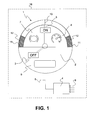
- FIG. 1 an inventive device 1 for displaying driving conditions of a hybrid vehicle 16 is shown schematically.
- the device 1 has for this purpose a circular display surface 2 with an associated pointer means 3.
- the pointing means 3 is connected by means of a line 5 to a control device 4.
- the control device 4 has inputs 6 for various signals such as vehicle weight, state of charge of the electrical storage, driving speed, engine temperature and the like.
- the display surface 2 is divided into a brake area 7 and an acceleration area 8.
- the display surface 2 has a stop area 9 in which the pointer means 3 shown in dashed lines shows when the vehicle is turned off completely without function.
- the brake area 7 and the acceleration area 8 share a middle side 10 lying in the middle.
- the pointer means 3 will predominantly in the area of Gutseite 10, d. H. move in the upper middle area of the display surface 2.
- the indicator means 3 moves according to the driving state either in the braking area 7 or in the acceleration area 8 further outwards in the direction of the bad sides 11th
- Both the brake area 7 and the acceleration area 8 are again subdivided.
- the two cross-hatched areas shown in each case 12 are covered by the pointer means 3, when the use of the service brake in addition to the braking function of Electric motor or the use of the internal combustion engine in addition to the electric motor takes place.
- a driver of in Fig. 1 illustrated embodiment immediately that the vehicle is in the on state, since the pointer means 3 is located in the upper half, and thus outside the stop area.
- Fig. 2 Now, another embodiment of a display 1 according to the invention is shown, in which the boundary regions 12 are additionally divided in itself.
- the boundary regions 12 have additional transition regions 13, which are swept over, for example, when the application pressure is applied to the service brake in the case of the braking region 7, as long as the service brake is present but still has no appreciable braking effect.
- the transition region 13 can be swept by the pointer means 3 when the engine is already started, but still does not provide any additional thrust.
- the scaling 14 consists of numbers without units, with the numerical values of the scaling increasing towards the good page 10.
- the values of the scaling can be integrated, for example, in the control device, via the travel path and / or the travel time, and the result can be output in a display field 15 as a value.
- the driver thus receives a quantitative feedback regarding the quality of his driving style. If the driver achieves a particularly high numerical value in the embodiments shown, this corresponds to a particularly energy-saving driving style.
Abstract
Description
Die vorliegende Erfindung betrifft eine Vorrichtung sowie ein Verfahren zur Anzeige von Fahrzuständen eines Hybridfahrzeuges mit einer Anzeigefläche und einem zugehörigen Zeigermittel, sowie einer Steuerungseinrichtung zur Ansteuerung des Zeigermittels.The present invention relates to a device and a method for displaying driving conditions of a hybrid vehicle having a display surface and an associated pointer means, and a control device for controlling the pointer means.
Aus der
Aufgabe der vorliegenden Erfindung ist es daher eine Anzeigevorrichtung mit einer verbesserten Ablesbarkeit und Informationsbereitstellung zu schaffen.Object of the present invention is therefore to provide a display device with improved readability and information provision.
Diese Aufgaben werden mit einer Vorrichtung gemäß den Merkmalen des Patentanspruchs 1 sowie des Verfahrensanspruchs 5 gelöst. Weitere vorteilhafte Ausgestaltungen der Erfindung sind in den abhängig formulierten Patentansprüchen angegeben. Es wird darauf hingewiesen, dass die in den abhängig formulierten Patentansprüchen einzelnen aufgeführten Merkmale in beliebiger technologisch sinnvoller Weise miteinander kombiniert werden können und weitere Ausgestaltungen der Erfindung definieren. Darüber hinaus werden die in den Patentansprüchen angegebenen Merkmale in der Beschreibung näher präzisiert und erläutert, wobei weitere bevorzugte Ausführungsbeispiele der Erfindung dargestellt werden.These objects are achieved with a device according to the features of
Zur Lösung der vorgenannten Aufgabe weist die Vorrichtung zur Anzeige von Fahrzeugzuständen eines Hybridfahrzeuges mit einer Anzeigefläche und einem zugehörigen Zeigermittel sowie einer Steuerungseinrichtung zur Ansteuerung des Zeigermittels zusätzlich wenigstens einen Brems- und einen Beschleunigungsbereich auf, wobei der Informationsinhalt der Anzeigefläche unveränderlich festgelegt ist. Unter Fahrzuständen eines Hybridfahrzeuges sind unter anderem drei Zustände zu verstehen. Es handelt sich dabei um den Brems-, den Beschleunigungs- und den Stoppzustand. Unter einem Hybridfahrzeug wird im Rahmen der vorliegenden Erfindung jegliche Art von Hybridfahrzeugen verstanden, insbesondere solche mit seriellen und/oder parallelen Hybridantrieben. Weiterhin ist unter dem Begriff Zeigermittel vorzugsweise ein auf einer Drehachse angeordneter mechanischer Zeiger zu verstehen. Darüber hinaus können aber auch andere Zeigermittel, wie beispielsweise auf einem LCD-Bildschirm dargestellte Pfeile oder sonstige Symbole zur Anzeige eines bestimmten Ortes auf der Anzeigefläche dienen und damit als Zeigermittel Verwendung finden. Die ebenfalls verwendete Steuerungseinrichtung ist vorzugsweise als elektronische Datenverarbeitungsanlage ausgebildet, die dazu geeignet ist unter Ausführung bestimmter vorgegebener Programme und Regeln in Folge von Eingangssignalen wenigstens ein definiertes Ausgangssignal zu erzeugen. Die Steuerungseinrichtung ist dabei so mit den Zeigermitteln verbunden, dass die Stellung der Zeigermittel durch die Ausgangsignale der Steuerungseinrichtung vorgegeben werden kann.To achieve the above object, the device for displaying vehicle states of a hybrid vehicle having a display surface and an associated pointer means and a control device for controlling the pointer means additionally at least a braking and an acceleration range, wherein the information content of the display surface is fixed immutable. Driving conditions of a hybrid vehicle include three states. These are the braking, accelerating and stopping states. Under a hybrid vehicle is under the The present invention means any kind of hybrid vehicles, in particular those with serial and / or parallel hybrid drives. Furthermore, the term pointer means is preferably to be understood as a mechanical pointer arranged on an axis of rotation. In addition, however, other pointer means, such as arrows shown on an LCD screen or other symbols for displaying a specific location on the display surface can be used and thus find use as a pointer means. The control device also used is preferably designed as an electronic data processing system which is capable of generating at least one defined output signal by executing certain predetermined programs and rules as a result of input signals. The control device is connected to the pointer means so that the position of the pointer means can be specified by the output signals of the control device.
Bei einer besonders einfachen und bevorzugten Ausführungsform der Erfindung ist nun vorgesehen, dass die Vorrichtung wenigstens einen Brems- und einen Beschleunigungsbereich aufweist, der vorzugsweise auf der Anzeigefläche ausgebildet ist und der auf der Anzeigefläche ausgegebene Informationsinhalt unveränderlich festgelegt ist. Unter Informationsinhalt wird die Art und der Umfang der dargestellten Informationen verstanden. Hierbei können beispielsweise im Rahmen einer Umschaltung zwischen Tagfahrlicht und Nachtfahrlicht durchaus Veränderungen der Anzeigefläche auftreten, ohne deren Informationsinhalt zu verändern. Durch die Verwendung einer unveränderlichen Anzeigefläche in Kombination mit einem einfachen Zeigermittel ist es nun möglich die von der Steuerungseinrichtung ermittelten Fahrzustände in besonders einfacher und somit für einen Fahrer schnell erfassbaren Weise darzustellen. Der Fahrer wird von unnötigen Zusatzinformationen entlastet und kann in sehr kurzer Zeit erfassen, ob es sich um einen Brems- oder Beschleunigungszustand handelt und darüber hinaus anhand der Zeigermittel ablesen, ob es sich um einen guten oder schlechten Brems- oder Beschleunigungsvorgang und damit einen energetisch sinnvolleren oder wenig sinnvolleren Fahrzustand handelt. Die stets unveränderliche Anzeigefläche entlastet den Fahrer dabei von jeglichen Interpretationstätigkeiten.In a particularly simple and preferred embodiment of the invention, it is now provided that the device has at least one braking and one acceleration region, which is preferably formed on the display surface and the information content output on the display surface is fixed immutable. Information content is understood to mean the nature and scope of the information presented. In this case, changes in the display area, for example, within the context of a switch between daytime running lights and night driving lights, can occur without altering their information content. By using a fixed display area in combination with a simple pointer means, it is now possible to represent the driving conditions determined by the control device in a particularly simple manner and thus quickly detectable by a driver. The driver is relieved of unnecessary additional information and can detect in a very short time, whether it is a braking or acceleration state and also read off the pointer means, whether it is a good or bad braking or acceleration process and thus a more energetically sensible or less sensible driving condition. The always unchanging display area relieves the driver of any interpretation activities.
Bei einer besonders bevorzugten Weiterbildung der Erfindung ist vorgesehen, dass zusätzlich wenigstens ein weiterer Stoppbereich vorgesehen ist, in den das Zeigermittel zeigt, wenn das Hybridfahrzeug funktionslos abgestellt ist. Hierdurch kann eine zusätzliche Information von der Vorrichtung bereitgestellt werden. Bei bekannten Anzeigen ist es nämlich nicht oder nur schwer möglich zu erkennen, ob das Fahrzeug funktionslos abgestellt ist oder sich funktionsbereit im Stillstand befindet.In a particularly preferred embodiment of the invention, it is provided that in addition at least one further stop area is provided into which the pointing means points when the hybrid vehicle is parked without function. As a result, additional information can be provided by the device. For known ads, it is not or It is difficult to detect whether the vehicle is parked without function or is ready for operation at standstill.
Weiterhin besonders vorteilhaft ist es, wenn wenigstens der Brems- oder der Beschleunigungsbereich zur Anzeige mehrerer unterschiedlicher Fahrzustände ausgebildet ist. Hierbei sind beide Bereiche in sich nochmals unterteilt und ermöglichen die Darstellung von unterschiedlichen Fahrzuständen wie z. B. starkes oder weniger starkes Bremsen, starkes oder weniger starkes Beschleunigen, rein elektrisches Bremsen, rein elektrisches Antreiben, kombiniertes Antreiben mit Verbrennungsmotor und Elektromotor oder kombiniertes Bremsen mit Betriebsbremse und Elektromotor.It is furthermore particularly advantageous if at least the braking or acceleration region is designed to display a plurality of different driving states. Here, both areas are divided again and allow the representation of different driving conditions such. B. strong or less strong braking, strong or less strong acceleration, pure electric braking, purely electric driving, combined driving with internal combustion engine and electric motor or combined braking with service brake and electric motor.
Bei einer ganz besonders bevorzugten Ausführungsform der vorliegenden Erfindung ist weiterhin vorgesehen, dass wenigstens der Brems- oder der Beschleunigungsbereich eine Gutseite und eine Schlechtseite aufweist. Hierdurch wird dem Fahrer eine besonders einfache Erkennung von energetisch günstigen Fahrzuständen ermöglicht, indem das Zeigermittel möglichst im Bereich der Gutseite des jeweiligen Bereichs gehalten werden soll.In a particularly preferred embodiment of the present invention, it is further provided that at least the braking or the acceleration region has a good side and a bad side. As a result, the driver a particularly simple detection of energetically favorable driving conditions is made possible by the pointer means should be kept as close as possible to the good side of each area.
Das erfindungsgemäße Verfahren auf das sich die Erfindung ferner richtet, zeichnet sich dadurch aus, dass mittels der Steuerungseinrichtung der aktuelle Brems- oder Beschleunigungszustand ermittelt und danach mit dem Zeigermittel auf einer unveränderlichen Anzeigefläche angezeigt wird. Die Steuerungseinrichtung wird dazu genutzt, um verschiedene Informationen, wie beispielsweise den Speicherinhalt des elektrischen Energiespeichers, die Dynamik der Gaspedalbewegungen und die absolute Stellung des Gaspedals auszuwerten und ein entsprechendes Signal mittels des Zeigermittels auszugeben. Grundsätzlich dient dabei die Steuerungseinrichtung dazu eine Mehrzahl unterschiedlichster Eingangssignale, welche Parameter und Informationen repräsentieren, zusammenzufügen zu einem einzigen Ausgangssignal an den Fahrer. Der Fahrer wird hierdurch in besonders effizienter Weise von den Interpretationsaufgaben entlastet. Neben den genannten beispielhaften Signalen bzw. Informationen können aber auch weitere Informationen, wie etwa die Motortemperatur, Topografieinformation oder ähnliches von der Steuerungseinrichtung mitberücksichtigt werden.The method according to the invention, to which the invention is further directed, is characterized in that the current braking or acceleration state is determined by means of the control device and then displayed on a fixed display surface with the pointer means. The control device is used to evaluate various information, such as the memory contents of the electric energy storage, the dynamics of the accelerator pedal movements and the absolute position of the accelerator pedal and output a corresponding signal by means of the pointer means. Basically, the control device serves to a plurality of different input signals, which represent parameters and information, combine to form a single output signal to the driver. The driver is thus relieved of the interpretation tasks in a particularly efficient manner. In addition to the exemplary signals or information mentioned, however, other information such as the engine temperature, topography information or the like can also be taken into account by the control device.
Besonders vorteilhaft ist es dabei, wenn ein Stoppzustand angezeigt wird, wenn das Fahrzeug funktionslos abgestellt ist. Ein Fahrer erkennt dann anhand der einfachen Anzeige sofort, ob sich das Fahrzeug in einem betriebsbereiten Zustand befindet oder in einem vollständig funktionslosen Zustand, wie er beispielsweise beim Abstellen und Parken eines Fahrzeuges vorliegt. Der Fahrer kann so den Betriebszustand des Fahrzeuges ähnlich einfach ablesen, wie es bei analogen Drehzahlmessern der Fall ist. Dies ist von besonderer Bedeutung, da bei den erfindungsgemäßen Fahrzeugen im Stand akustische oder mechanische Rückmeldungen, beispielsweise durch Vibrationen oder Motorgeräusche, nicht gegeben sind.It is particularly advantageous if a stop state is displayed when the vehicle is parked without function. A driver then recognizes on the basis of the simple display immediately whether the vehicle is in an operational state or in a completely non-functional state, such as when parking and parking a Vehicle is present. The driver can thus read the operating state of the vehicle similarly easy, as is the case with analog tachometers. This is of particular importance, since in the vehicles according to the invention in the state of acoustic or mechanical feedback, for example, by vibration or engine noise, are not given.
Schließlich ist es bei einem weiteren besonders bevorzugten und vorteilhaften Ausführungsbeispiel der vorliegenden Erfindung vorgesehen, dass mittels der Steuerungseinrichtung ein bestimmter Fahrzustand aus einer Mehrzahl vorbekannter Fahrzustände ermittelt und dieser Fahrzustand in Abhängigkeit von einem Fahrzeugzustand zwischen einer Gutseite und einer Schlechtseite des Brems- oder Beschleunigungsbereichs angezeigt wird. Unter einem Fahrzustand ist dabei jegliche die Lage oder Bewegung des Fahrzeuges betreffen Information zu verstehen. Dies sind insbesondere Geschwindigkeit, Fahrzeugneigung.Finally, in another particularly preferred and advantageous exemplary embodiment of the present invention, it is provided that a specific driving state is determined from a plurality of previously known driving states by means of the control device and this driving state is displayed as a function of a vehicle condition between a good side and a bad side of the braking or acceleration region , A driving state is understood to be any information concerning the position or movement of the vehicle. These are in particular speed, vehicle inclination.
Unter dem Fahrzeugzustand wiederum ist eine Vielzahl von Parameter, wie Fahrzeuggewicht, Motortemperatur, Füllstand der Energiespeicher, Temperatur der Energiespeicher etc. zu verstehen. Hierdurch wird es möglich noch genauer zwischen energetisch sinnvollen und energetisch weniger sinnvollen Fahrweisen zu differenzieren. So kann beispielsweise im Falle einer Zuschaltung eines Verbrennungsmotors zwischen den Fällen unterschieden werden, bei denen eine Zuschaltung aufgrund des leeren elektrischen Energiespeichers unbedingt erforderlich ist und solchen, bei denen die Zuschaltung des Verbrennungsmotors aufgrund eines übermäßigen Leistungsabrufes erfolgt. Während die Zuschaltung bei leerem elektrischen Energiespeicher gerechtfertigt ist, deutet die Zuschaltung des Verbrennungsmotors durch übermäßigen Leistungsabruf auf eine unökonomische Fahrweise hin. Berücksichtigt man nun weitere Größen, wie beispielsweise die Fahrbahnsteigung oder die Fahrzeugneigung und das Fahrzeuggewicht, kann ermittelt werden, ob der zusätzliche Leistungsabruf gerechtfertigt ist oder nicht. Dies kann dann mit einer entsprechenden Stellung des Zeigermittels auf der Anzeigefläche ausgegeben werden. Neben der besonders einfachen Ablesbarkeit stellt sich darüber hinaus ein Trainingseffekt für den Fahrer ein, so dass dessen Fahrweise verbrauchsgünstiger wird.Under the vehicle state in turn is a variety of parameters, such as vehicle weight, engine temperature, level of energy storage, temperature of the energy storage, etc. to understand. This makes it possible to differentiate even more precisely between energetically sensible and energetically less sensible modes of operation. Thus, for example, in the case of a connection of an internal combustion engine, a distinction can be made between the cases in which a connection due to the empty electrical energy storage is absolutely necessary and those in which the connection of the internal combustion engine takes place due to an excessive Leistungsabrufes. While the connection is justified when the electric energy storage is empty, the connection of the internal combustion engine by excessive power demand indicates an uneconomical driving style. Taking into account other variables, such as the road gradient or the vehicle inclination and the vehicle weight, it can be determined whether the additional power demand is justified or not. This can then be output with a corresponding position of the pointer means on the display surface. In addition to the particularly easy readability beyond a training effect for the driver is, so that his driving is more economical.
Vorzugsweise erfolgt dabei die Darstellung des Fahrzustandes durch das Zeigermittel auf einer skalierten Anzeigefläche. Die der Skalierung zugewiesenen Werte können so beispielsweise über die Fahrtdauer und/oder über die Fahrtstrecke integriert werden. Im Ergebnis führt dies zu einer Bonus-Malus-Ermittlung, die einem Fahrer beispielsweise in einem weiteren Anzeigefenster der Vorrichtung ausgegeben werden kann.In this case, the representation of the driving state by the pointing device preferably takes place on a scaled display area. The values assigned to the scaling can thus be integrated, for example, over the travel time and / or over the route. In the result This leads to a bonus penalty determination that can be output to a driver, for example, in another display window of the device.
Nachfolgend wird die Erfindung sowie das technische Umfeld nun anhand der Figuren näher erläutert. Es ist darauf hinzuweisen, dass die Figuren besonders bevorzugte Ausführungsvarianten der Erfindung zeigen, auf die sie jedoch nicht beschränkt ist. In der Zeichnung zeigen schematisch:
- Fig. 1
- eine erste Ausführungsform einer erfindungsgemäßen Vorrichtung;
- Fig. 2
- eine zweite Ausführungsform einer erfindungsgemäßen Vorrichtung und
- Fig. 3
- eine dritte Ausführungsform einer erfindungsgemäßen Vorrichtung.
- Fig. 1
- a first embodiment of a device according to the invention;
- Fig. 2
- a second embodiment of a device according to the invention and
- Fig. 3
- A third embodiment of a device according to the invention.
In
Bei der hier gezeigten Ausführungsform teilen sich der Bremsbereich 7 und der Beschleunigungsbereich 8 eine in der Mitte liegende Gutseite 10. An der gegenüberliegenden Seite des Bremsbereiches 7 bzw. des Beschleunigungsbereiches 8 finden sich jeweils zugehörige Schlechtseiten 11. Fährt ein Fahrer nun energetisch besonders sinnvoll, so wird sich das Zeigermittel 3 überwiegend im Bereich der Gutseite 10, d. h. im oberen mittleren Bereich der Anzeigefläche 2 bewegen. Sofern eine energetisch weniger sinnvolle Fahrweise gewählt wird, bewegt sich das Zeigermittel 3 entsprechend dem Fahrzustand entweder im Bremsbereich 7 oder im Beschleunigungsbereich 8 weiter nach außen in Richtung der Schlechtseiten 11.In the embodiment shown here, the
Sowohl der Bremsbereich 7 als auch der Beschleunigungsbereich 8 sind in sich nochmals unterteilt. Die beiden jeweils schraffiert dargestellten Grenzbereiche 12 werden vom Zeigermittel 3 überstrichen, wenn der Einsatz der Betriebsbremse zusätzlich zur Bremsfunktion des Elektromotors oder der Einsatz des Verbrennungsmotors zusätzlich zum Elektromotor erfolgt.Both the
Darüber hinaus kann ein Fahrer der in
In
Schließlich ist in
Im Übrigen wird darauf hingewiesen, dass die vorliegende Erfindung nicht auf die dargestellten Ausführungsbeispiele beschränkt ist. Es sind vielmehr zahlreiche Abwandlungen der Erfindung im Rahmen der Patentansprüche möglich, ohne den Grundgedanken der Erfindung zu verlassen.Incidentally, it should be noted that the present invention is not limited to the illustrated embodiments. Rather, numerous modifications of the invention within the scope of the claims are possible without departing from the spirit of the invention.
- 1)1)
- Vorrichtungcontraption
- 2)2)
- Anzeigeflächedisplay area
- 3)3)
- Zeigermittelpointer means
- 4)4)
- Steuerungseinrichtungcontrol device
- 5)5)
- Leitungmanagement
- 6)6)
- Eingangentrance
- 7)7)
- Bremsbereichbraking range
- 8)8th)
- Beschleunigungsbereichacceleration range
- 9)9)
- Stoppbereichstop area
- 10)10)
- Gutseitegood side
- 11)11)
- Schlechtseitebad side
- 12)12)
- Grenzbereichborder area
- 13)13)
- ÜbergangsbereichTransition area
- 14)14)
- Skalierungscaling
- 15)15)
- Anzeigefelddisplay
- 16)16)
- Hybridfahrzeughybrid vehicle
Claims (7)
dadurch gekennzeichnet, dass
diese wenigstens einen Brems- und einen Beschleunigungsbereich (7, 8) aufweist und der Informationsinhalt der Anzeigefläche (2) unveränderlich festgelegt ist.Device (1) for displaying driving conditions of a hybrid vehicle (16) with a display surface (2) and an associated pointer means (3), and a control device (4) for actuating the pointer means (3),
characterized in that
this has at least one braking and an acceleration region (7, 8) and the information content of the display surface (2) is fixed immutable.
dadurch gekennzeichnet, dass
zusätzlich wenigstens ein weiterer Stoppbereich (9) vorgesehen ist, in den das Zeigermittel (3) zeigt, wenn das Hybridfahrzeug (16) funktionslos abgestellt ist.Device according to the preceding claim,
characterized in that
In addition, at least one further stop area (9) is provided, into which the pointing means (3) points when the hybrid vehicle (16) is parked without function.
dadurch gekennzeichnet, dass
wenigstens der Brems- oder der Beschleunigungsbereich (7, 8) zur Anzeige mehrere unterschiedlicher Fahrzustände ausgebildet ist.Device according to one of the preceding claims,
characterized in that
at least the braking or the acceleration range (7, 8) is designed to display a plurality of different driving conditions.
dadurch gekennzeichnet, dass
wenigstens der Brems- oder der Beschleunigungsbereich (7, 8) eine Gutseite (10) und eine Schlechtseite (11) aufweist.Device according to one of the preceding claims,
characterized in that
at least the braking or acceleration region (7, 8) has a good side (10) and a bad side (11).
dadurch gekennzeichnet, dass
mittels der Steuerungseinrichtung (4) der aktuelle Brems- oder Beschleunigungszustand ermittelt und
danach mit dem Zeigermittel (3) auf der unveränderlichen Anzeigefläche (2) angezeigt wird.Method for displaying driving states of a hybrid vehicle (16) with a display surface (2) and an associated pointer means (3), and a control device (4) for actuating the pointer means (3),
characterized in that
determined by the control device (4) of the current braking or acceleration state and
thereafter displayed on the fixed display surface (2) with the pointer means (3).
dadurch gekennzeichnet, dass
das ein Stoppzustand angezeigt wird, wenn das Hybridfahrzeug (16) funktionslos abgestellt ist.Method according to the preceding claim,
characterized in that
a stop state is displayed when the hybrid vehicle (16) is disabled.
dadurch gekennzeichnet, dass
mittels der Steuerungseinrichtung ein bestimmter Fahrzustand aus einer Mehrzahl vorbekannter Fahrzustände ermittelt wird und dieser Fahrzustand in Abhängigkeit von einem Fahrzeugzustand zwischen einer Gutseite und einer Schlechtseite des Brems- oder Beschleunigungsbereichs angezeigt wird.Method according to one of the preceding claims,
characterized in that
a specific driving state from a plurality of previously known driving states is determined by the control device and this driving state is displayed as a function of a vehicle state between a good side and a bad side of the braking or acceleration region.
Applications Claiming Priority (1)
| Application Number | Priority Date | Filing Date | Title |
|---|---|---|---|
| DE102009035139A DE102009035139A1 (en) | 2009-07-29 | 2009-07-29 | Method and device for displaying driving conditions of a hybrid vehicle |
Publications (3)
| Publication Number | Publication Date |
|---|---|
| EP2279890A2 true EP2279890A2 (en) | 2011-02-02 |
| EP2279890A3 EP2279890A3 (en) | 2018-04-25 |
| EP2279890B1 EP2279890B1 (en) | 2019-10-02 |
Family
ID=43038123
Family Applications (1)
| Application Number | Title | Priority Date | Filing Date |
|---|---|---|---|
| EP10004379.3A Active EP2279890B1 (en) | 2009-07-29 | 2010-04-24 | Method and device for displaying the driving status of a hybrid vehicle |
Country Status (5)
| Country | Link |
|---|---|
| EP (1) | EP2279890B1 (en) |
| CN (1) | CN101987576B (en) |
| BR (1) | BRPI1002535B8 (en) |
| DE (1) | DE102009035139A1 (en) |
| RU (1) | RU2503927C2 (en) |
Cited By (1)
| Publication number | Priority date | Publication date | Assignee | Title |
|---|---|---|---|---|
| EP3406475A1 (en) * | 2017-05-18 | 2018-11-28 | Mitsubishi Jidosha Kogyo Kabushiki Kaisha | Display device for hybrid vehicle |
Families Citing this family (8)
| Publication number | Priority date | Publication date | Assignee | Title |
|---|---|---|---|---|
| DE102011112643B4 (en) * | 2011-09-07 | 2020-11-05 | Volkswagen Aktiengesellschaft | Display device for a hybrid vehicle and method for display and hybrid vehicle |
| DE102011112707B4 (en) * | 2011-09-07 | 2020-11-05 | Volkswagen Aktiengesellschaft | Display device for a hybrid vehicle and method for display and hybrid vehicle |
| DE102012009736A1 (en) | 2012-05-16 | 2013-11-21 | Audi Ag | Device for displaying information in a hybrid vehicle |
| JP6630698B2 (en) * | 2017-03-24 | 2020-01-15 | 矢崎総業株式会社 | Display device for vehicles |
| WO2019205012A1 (en) * | 2018-04-25 | 2019-10-31 | 深圳市元征软件开发有限公司 | Digital dashboard display method and digital dashboard display device |
| CN109677265B (en) * | 2018-12-25 | 2022-03-29 | 大陆汽车车身电子系统(芜湖)有限公司 | Digital instrument and display method thereof |
| CN113631412B (en) * | 2019-03-25 | 2024-01-19 | 三菱自动车工业株式会社 | Display device |
| JP7173289B2 (en) * | 2019-03-28 | 2022-11-16 | 三菱自動車工業株式会社 | Display device |
Citations (1)
| Publication number | Priority date | Publication date | Assignee | Title |
|---|---|---|---|---|
| DE19533829C1 (en) | 1995-09-13 | 1996-09-19 | Daimler Benz Ag | Tractive power monitor for vehicles with electric or hybrid drive |
Family Cites Families (9)
| Publication number | Priority date | Publication date | Assignee | Title |
|---|---|---|---|---|
| US4166382A (en) * | 1978-03-27 | 1979-09-04 | Petersen Paul S | Auto economy gauge |
| JP3385724B2 (en) * | 1994-05-27 | 2003-03-10 | 株式会社エクォス・リサーチ | Display device for hybrid vehicle |
| US5929595A (en) * | 1997-11-21 | 1999-07-27 | Lockheed Martin Corporation | Hybrid electric vehicle with traction motor drive allocated between battery and auxiliary source depending upon battery charge state |
| US6480106B1 (en) * | 2000-12-11 | 2002-11-12 | Ford Global Technologies, Inc. | Rate of consumption gauge with variable rate of consumption limits |
| DE10131262A1 (en) * | 2001-06-29 | 2003-01-16 | Siemens Ag | Gauge |
| JP4725530B2 (en) * | 2007-02-20 | 2011-07-13 | トヨタ自動車株式会社 | Vehicle display device |
| US7671567B2 (en) * | 2007-06-15 | 2010-03-02 | Tesla Motors, Inc. | Multi-mode charging system for an electric vehicle |
| JP5141131B2 (en) * | 2007-08-08 | 2013-02-13 | トヨタ自動車株式会社 | Vehicle driving support apparatus and method |
| KR101356197B1 (en) * | 2007-12-12 | 2014-01-27 | 기아자동차주식회사 | System for Guiding Fuel Economy Driving |
-
2009
- 2009-07-29 DE DE102009035139A patent/DE102009035139A1/en not_active Ceased
-
2010
- 2010-04-24 EP EP10004379.3A patent/EP2279890B1/en active Active
- 2010-07-01 BR BRPI1002535A patent/BRPI1002535B8/en active IP Right Grant
- 2010-07-28 RU RU2010131825/11A patent/RU2503927C2/en active
- 2010-07-29 CN CN201010248828.0A patent/CN101987576B/en active Active
Patent Citations (1)
| Publication number | Priority date | Publication date | Assignee | Title |
|---|---|---|---|---|
| DE19533829C1 (en) | 1995-09-13 | 1996-09-19 | Daimler Benz Ag | Tractive power monitor for vehicles with electric or hybrid drive |
Cited By (2)
| Publication number | Priority date | Publication date | Assignee | Title |
|---|---|---|---|---|
| EP3406475A1 (en) * | 2017-05-18 | 2018-11-28 | Mitsubishi Jidosha Kogyo Kabushiki Kaisha | Display device for hybrid vehicle |
| US10639994B2 (en) | 2017-05-18 | 2020-05-05 | Mitsubishi Jidosha Kogyo Kabushiki Kaisha | Display device for hybrid vehicle |
Also Published As
| Publication number | Publication date |
|---|---|
| RU2010131825A (en) | 2012-02-10 |
| EP2279890A3 (en) | 2018-04-25 |
| DE102009035139A1 (en) | 2011-02-03 |
| CN101987576B (en) | 2014-06-11 |
| BRPI1002535B1 (en) | 2020-11-10 |
| BRPI1002535A2 (en) | 2012-03-13 |
| CN101987576A (en) | 2011-03-23 |
| EP2279890B1 (en) | 2019-10-02 |
| RU2503927C2 (en) | 2014-01-10 |
| BRPI1002535B8 (en) | 2022-03-22 |
Similar Documents
| Publication | Publication Date | Title |
|---|---|---|
| EP2279890B1 (en) | Method and device for displaying the driving status of a hybrid vehicle | |
| DE102015225617A1 (en) | Method for monitoring a drive-by-wire system of a motor vehicle | |
| EP2539198B1 (en) | Indicating device for a vehicle and method for generating an indication of an operation modus on a vehicle indicating device | |
| DE102011108446B4 (en) | Method and device for recuperation for a vehicle | |
| DE102013222048A1 (en) | Method and device for activating or deactivating an automatic driving function | |
| DE19843395A1 (en) | Method for speed and / or distance control in motor vehicles | |
| DE102013010630A1 (en) | Device and method for selectively operating a motor vehicle in a user-controlled or an automatic driving mode | |
| WO2018192800A1 (en) | Method for assistance of a driving manoeuver, and assistance system for a driving manoeuver | |
| EP2441595B1 (en) | Driver assistance system for a motor vehicle and method for operating same | |
| WO2006037360A1 (en) | Driver information system for information on the possibility of carrying out overtaking manoeuvres | |
| DE19931161A1 (en) | Distance-sensitive, speed-controlled motor-vehicle road travel method, involves evaluation of predictive data about road conditions | |
| DE102011112707B4 (en) | Display device for a hybrid vehicle and method for display and hybrid vehicle | |
| DE102008040982A1 (en) | Driver information device for predictive warning of the driver of a vehicle at excessive speed | |
| DE102017206695A1 (en) | Driver assistance method for assisting a performance-intensive driving maneuver of an ego vehicle and driver assistance system for a performance-intensive driving maneuver of an ego vehicle | |
| DE102019108502A1 (en) | Method and control device for controlling an automatic emergency braking system | |
| DE102005017361B4 (en) | Control device for a driver assistance system | |
| DE102019126713A1 (en) | Method, system and computer program for operating an at least partially automated and / or remote-controlled vehicle | |
| EP2483577B1 (en) | Method for controlling and/or regulating an automated transmission | |
| DE102016102622A1 (en) | A method of reducing the amount of fuel consumed by an engine of a motor vehicle | |
| EP1214563B1 (en) | Representing the system state of a speed and distance control system | |
| DE102010030257A1 (en) | Driver assistance method for vehicle, involves detecting and evaluating state information of vehicle and environment properties of environment of vehicle | |
| DE10358968B4 (en) | Vehicle speed control device for a motor vehicle, which is connected to a navigation system | |
| DE102013209787A1 (en) | Driver type method for determining parameter e.g. speed of vehicle e.g. motor vehicle, involves determining driver type forward-looking route parameter of vehicle lying route based on determined driving activity of driver | |
| DE102014226296A1 (en) | Cruise control system and method for operating state optimization of a vehicle | |
| DE102015000402A1 (en) | Motor vehicle and method for operating a cruise control system |
Legal Events
| Date | Code | Title | Description |
|---|---|---|---|
| PUAI | Public reference made under article 153(3) epc to a published international application that has entered the european phase |
Free format text: ORIGINAL CODE: 0009012 |
|
| AK | Designated contracting states |
Kind code of ref document: A2 Designated state(s): AT BE BG CH CY CZ DE DK EE ES FI FR GB GR HR HU IE IS IT LI LT LU LV MC MK MT NL NO PL PT RO SE SI SK SM TR |
|
| AX | Request for extension of the european patent |
Extension state: AL BA ME RS |
|
| RAP1 | Party data changed (applicant data changed or rights of an application transferred) |
Owner name: MAN TRUCK & BUS AG |
|
| PUAL | Search report despatched |
Free format text: ORIGINAL CODE: 0009013 |
|
| AK | Designated contracting states |
Kind code of ref document: A3 Designated state(s): AT BE BG CH CY CZ DE DK EE ES FI FR GB GR HR HU IE IS IT LI LT LU LV MC MK MT NL NO PL PT RO SE SI SK SM TR |
|
| AX | Request for extension of the european patent |
Extension state: AL BA ME RS |
|
| RIC1 | Information provided on ipc code assigned before grant |
Ipc: B60R 16/023 20060101ALI20180319BHEP Ipc: G01D 7/08 20060101ALI20180319BHEP Ipc: G06T 19/00 20110101ALI20180319BHEP Ipc: B60Q 9/00 20060101ALI20180319BHEP Ipc: G06K 9/00 20060101ALI20180319BHEP Ipc: B60R 1/00 20060101ALI20180319BHEP Ipc: B60K 35/00 20060101AFI20180319BHEP Ipc: B60K 37/02 20060101ALI20180319BHEP Ipc: G07C 5/00 20060101ALI20180319BHEP |
|
| STAA | Information on the status of an ep patent application or granted ep patent |
Free format text: STATUS: REQUEST FOR EXAMINATION WAS MADE |
|
| 17P | Request for examination filed |
Effective date: 20181022 |
|
| RIC1 | Information provided on ipc code assigned before grant |
Ipc: B60R 1/00 20060101ALI20190408BHEP Ipc: G01D 7/08 20060101ALI20190408BHEP Ipc: B60K 35/00 20060101AFI20190408BHEP Ipc: B60Q 9/00 20060101ALI20190408BHEP Ipc: G06K 9/00 20060101ALI20190408BHEP Ipc: G06T 19/00 20110101ALI20190408BHEP Ipc: G07C 5/00 20060101ALI20190408BHEP Ipc: B60K 37/02 20060101ALI20190408BHEP Ipc: B60R 16/023 20060101ALI20190408BHEP |
|
| GRAP | Despatch of communication of intention to grant a patent |
Free format text: ORIGINAL CODE: EPIDOSNIGR1 |
|
| STAA | Information on the status of an ep patent application or granted ep patent |
Free format text: STATUS: GRANT OF PATENT IS INTENDED |
|
| INTG | Intention to grant announced |
Effective date: 20190521 |
|
| RAP1 | Party data changed (applicant data changed or rights of an application transferred) |
Owner name: MAN TRUCK & BUS SE |
|
| GRAS | Grant fee paid |
Free format text: ORIGINAL CODE: EPIDOSNIGR3 |
|
| GRAA | (expected) grant |
Free format text: ORIGINAL CODE: 0009210 |
|
| STAA | Information on the status of an ep patent application or granted ep patent |
Free format text: STATUS: THE PATENT HAS BEEN GRANTED |
|
| AK | Designated contracting states |
Kind code of ref document: B1 Designated state(s): AT BE BG CH CY CZ DE DK EE ES FI FR GB GR HR HU IE IS IT LI LT LU LV MC MK MT NL NO PL PT RO SE SI SK SM TR |
|
| REG | Reference to a national code |
Ref country code: GB Ref legal event code: FG4D Free format text: NOT ENGLISH |
|
| RIN1 | Information on inventor provided before grant (corrected) |
Inventor name: DOERNER, KARLHEINZ Inventor name: KRUECKL, WOLFGANG Inventor name: MICHEL, BRITTA Inventor name: DRIMML, PETER Inventor name: MOHRA, HOLGER Inventor name: KERSCHL, STEFAN |
|
| REG | Reference to a national code |
Ref country code: CH Ref legal event code: EP Ref country code: AT Ref legal event code: REF Ref document number: 1185807 Country of ref document: AT Kind code of ref document: T Effective date: 20191015 |
|
| RIN2 | Information on inventor provided after grant (corrected) |
Inventor name: DRIMML, PETER Inventor name: DOERNER, KARLHEINZ Inventor name: KRUECKL, WOLFGANG Inventor name: MOHRA, HOLGER Inventor name: MICHEL, BRITTA Inventor name: KERSCHL, STEFAN |
|
| REG | Reference to a national code |
Ref country code: DE Ref legal event code: R096 Ref document number: 502010016280 Country of ref document: DE |
|
| REG | Reference to a national code |
Ref country code: IE Ref legal event code: FG4D Free format text: LANGUAGE OF EP DOCUMENT: GERMAN |
|
| REG | Reference to a national code |
Ref country code: SE Ref legal event code: TRGR |
|
| REG | Reference to a national code |
Ref country code: NL Ref legal event code: FP |
|
| REG | Reference to a national code |
Ref country code: LT Ref legal event code: MG4D |
|
| PG25 | Lapsed in a contracting state [announced via postgrant information from national office to epo] |
Ref country code: FI Free format text: LAPSE BECAUSE OF FAILURE TO SUBMIT A TRANSLATION OF THE DESCRIPTION OR TO PAY THE FEE WITHIN THE PRESCRIBED TIME-LIMIT Effective date: 20191002 Ref country code: BG Free format text: LAPSE BECAUSE OF FAILURE TO SUBMIT A TRANSLATION OF THE DESCRIPTION OR TO PAY THE FEE WITHIN THE PRESCRIBED TIME-LIMIT Effective date: 20200102 Ref country code: PT Free format text: LAPSE BECAUSE OF FAILURE TO SUBMIT A TRANSLATION OF THE DESCRIPTION OR TO PAY THE FEE WITHIN THE PRESCRIBED TIME-LIMIT Effective date: 20200203 Ref country code: ES Free format text: LAPSE BECAUSE OF FAILURE TO SUBMIT A TRANSLATION OF THE DESCRIPTION OR TO PAY THE FEE WITHIN THE PRESCRIBED TIME-LIMIT Effective date: 20191002 Ref country code: LV Free format text: LAPSE BECAUSE OF FAILURE TO SUBMIT A TRANSLATION OF THE DESCRIPTION OR TO PAY THE FEE WITHIN THE PRESCRIBED TIME-LIMIT Effective date: 20191002 Ref country code: LT Free format text: LAPSE BECAUSE OF FAILURE TO SUBMIT A TRANSLATION OF THE DESCRIPTION OR TO PAY THE FEE WITHIN THE PRESCRIBED TIME-LIMIT Effective date: 20191002 Ref country code: NO Free format text: LAPSE BECAUSE OF FAILURE TO SUBMIT A TRANSLATION OF THE DESCRIPTION OR TO PAY THE FEE WITHIN THE PRESCRIBED TIME-LIMIT Effective date: 20200102 Ref country code: PL Free format text: LAPSE BECAUSE OF FAILURE TO SUBMIT A TRANSLATION OF THE DESCRIPTION OR TO PAY THE FEE WITHIN THE PRESCRIBED TIME-LIMIT Effective date: 20191002 Ref country code: GR Free format text: LAPSE BECAUSE OF FAILURE TO SUBMIT A TRANSLATION OF THE DESCRIPTION OR TO PAY THE FEE WITHIN THE PRESCRIBED TIME-LIMIT Effective date: 20200103 |
|
| PG25 | Lapsed in a contracting state [announced via postgrant information from national office to epo] |
Ref country code: CZ Free format text: LAPSE BECAUSE OF FAILURE TO SUBMIT A TRANSLATION OF THE DESCRIPTION OR TO PAY THE FEE WITHIN THE PRESCRIBED TIME-LIMIT Effective date: 20191002 Ref country code: HR Free format text: LAPSE BECAUSE OF FAILURE TO SUBMIT A TRANSLATION OF THE DESCRIPTION OR TO PAY THE FEE WITHIN THE PRESCRIBED TIME-LIMIT Effective date: 20191002 Ref country code: IS Free format text: LAPSE BECAUSE OF FAILURE TO SUBMIT A TRANSLATION OF THE DESCRIPTION OR TO PAY THE FEE WITHIN THE PRESCRIBED TIME-LIMIT Effective date: 20200224 |
|
| REG | Reference to a national code |
Ref country code: DE Ref legal event code: R097 Ref document number: 502010016280 Country of ref document: DE |
|
| PG2D | Information on lapse in contracting state deleted |
Ref country code: IS |
|
| PG25 | Lapsed in a contracting state [announced via postgrant information from national office to epo] |
Ref country code: RO Free format text: LAPSE BECAUSE OF FAILURE TO SUBMIT A TRANSLATION OF THE DESCRIPTION OR TO PAY THE FEE WITHIN THE PRESCRIBED TIME-LIMIT Effective date: 20191002 Ref country code: EE Free format text: LAPSE BECAUSE OF FAILURE TO SUBMIT A TRANSLATION OF THE DESCRIPTION OR TO PAY THE FEE WITHIN THE PRESCRIBED TIME-LIMIT Effective date: 20191002 Ref country code: DK Free format text: LAPSE BECAUSE OF FAILURE TO SUBMIT A TRANSLATION OF THE DESCRIPTION OR TO PAY THE FEE WITHIN THE PRESCRIBED TIME-LIMIT Effective date: 20191002 Ref country code: IS Free format text: LAPSE BECAUSE OF FAILURE TO SUBMIT A TRANSLATION OF THE DESCRIPTION OR TO PAY THE FEE WITHIN THE PRESCRIBED TIME-LIMIT Effective date: 20200202 |
|
| PLBE | No opposition filed within time limit |
Free format text: ORIGINAL CODE: 0009261 |
|
| STAA | Information on the status of an ep patent application or granted ep patent |
Free format text: STATUS: NO OPPOSITION FILED WITHIN TIME LIMIT |
|
| PG25 | Lapsed in a contracting state [announced via postgrant information from national office to epo] |
Ref country code: SM Free format text: LAPSE BECAUSE OF FAILURE TO SUBMIT A TRANSLATION OF THE DESCRIPTION OR TO PAY THE FEE WITHIN THE PRESCRIBED TIME-LIMIT Effective date: 20191002 Ref country code: SK Free format text: LAPSE BECAUSE OF FAILURE TO SUBMIT A TRANSLATION OF THE DESCRIPTION OR TO PAY THE FEE WITHIN THE PRESCRIBED TIME-LIMIT Effective date: 20191002 |
|
| 26N | No opposition filed |
Effective date: 20200703 |
|
| PG25 | Lapsed in a contracting state [announced via postgrant information from national office to epo] |
Ref country code: SI Free format text: LAPSE BECAUSE OF FAILURE TO SUBMIT A TRANSLATION OF THE DESCRIPTION OR TO PAY THE FEE WITHIN THE PRESCRIBED TIME-LIMIT Effective date: 20191002 Ref country code: MC Free format text: LAPSE BECAUSE OF FAILURE TO SUBMIT A TRANSLATION OF THE DESCRIPTION OR TO PAY THE FEE WITHIN THE PRESCRIBED TIME-LIMIT Effective date: 20191002 |
|
| REG | Reference to a national code |
Ref country code: CH Ref legal event code: PL |
|
| PG25 | Lapsed in a contracting state [announced via postgrant information from national office to epo] |
Ref country code: LI Free format text: LAPSE BECAUSE OF NON-PAYMENT OF DUE FEES Effective date: 20200430 Ref country code: LU Free format text: LAPSE BECAUSE OF NON-PAYMENT OF DUE FEES Effective date: 20200424 Ref country code: CH Free format text: LAPSE BECAUSE OF NON-PAYMENT OF DUE FEES Effective date: 20200430 |
|
| REG | Reference to a national code |
Ref country code: BE Ref legal event code: MM Effective date: 20200430 |
|
| PG25 | Lapsed in a contracting state [announced via postgrant information from national office to epo] |
Ref country code: BE Free format text: LAPSE BECAUSE OF NON-PAYMENT OF DUE FEES Effective date: 20200430 |
|
| GBPC | Gb: european patent ceased through non-payment of renewal fee |
Effective date: 20200424 |
|
| PG25 | Lapsed in a contracting state [announced via postgrant information from national office to epo] |
Ref country code: IE Free format text: LAPSE BECAUSE OF NON-PAYMENT OF DUE FEES Effective date: 20200424 Ref country code: GB Free format text: LAPSE BECAUSE OF NON-PAYMENT OF DUE FEES Effective date: 20200424 |
|
| REG | Reference to a national code |
Ref country code: AT Ref legal event code: MM01 Ref document number: 1185807 Country of ref document: AT Kind code of ref document: T Effective date: 20200424 |
|
| PG25 | Lapsed in a contracting state [announced via postgrant information from national office to epo] |
Ref country code: AT Free format text: LAPSE BECAUSE OF NON-PAYMENT OF DUE FEES Effective date: 20200424 |
|
| PG25 | Lapsed in a contracting state [announced via postgrant information from national office to epo] |
Ref country code: TR Free format text: LAPSE BECAUSE OF FAILURE TO SUBMIT A TRANSLATION OF THE DESCRIPTION OR TO PAY THE FEE WITHIN THE PRESCRIBED TIME-LIMIT Effective date: 20191002 Ref country code: MT Free format text: LAPSE BECAUSE OF FAILURE TO SUBMIT A TRANSLATION OF THE DESCRIPTION OR TO PAY THE FEE WITHIN THE PRESCRIBED TIME-LIMIT Effective date: 20191002 Ref country code: CY Free format text: LAPSE BECAUSE OF FAILURE TO SUBMIT A TRANSLATION OF THE DESCRIPTION OR TO PAY THE FEE WITHIN THE PRESCRIBED TIME-LIMIT Effective date: 20191002 |
|
| PG25 | Lapsed in a contracting state [announced via postgrant information from national office to epo] |
Ref country code: MK Free format text: LAPSE BECAUSE OF FAILURE TO SUBMIT A TRANSLATION OF THE DESCRIPTION OR TO PAY THE FEE WITHIN THE PRESCRIBED TIME-LIMIT Effective date: 20191002 |
|
| PGFP | Annual fee paid to national office [announced via postgrant information from national office to epo] |
Ref country code: SE Payment date: 20230317 Year of fee payment: 14 |
|
| PGFP | Annual fee paid to national office [announced via postgrant information from national office to epo] |
Ref country code: NL Payment date: 20230424 Year of fee payment: 14 |
|
| PGFP | Annual fee paid to national office [announced via postgrant information from national office to epo] |
Ref country code: IT Payment date: 20230421 Year of fee payment: 14 Ref country code: FR Payment date: 20230421 Year of fee payment: 14 Ref country code: DE Payment date: 20230427 Year of fee payment: 14 |