EP2278897B1 - Système de charge pour article chaussant - Google Patents
Système de charge pour article chaussant Download PDFInfo
- Publication number
- EP2278897B1 EP2278897B1 EP09739666.7A EP09739666A EP2278897B1 EP 2278897 B1 EP2278897 B1 EP 2278897B1 EP 09739666 A EP09739666 A EP 09739666A EP 2278897 B1 EP2278897 B1 EP 2278897B1
- Authority
- EP
- European Patent Office
- Prior art keywords
- footwear
- article
- inductive loop
- housing
- external
- Prior art date
- Legal status (The legal status is an assumption and is not a legal conclusion. Google has not performed a legal analysis and makes no representation as to the accuracy of the status listed.)
- Active
Links
- 230000001939 inductive effect Effects 0.000 claims description 105
- 238000012546 transfer Methods 0.000 claims description 14
- 238000000034 method Methods 0.000 claims description 10
- 230000008878 coupling Effects 0.000 claims description 5
- 238000010168 coupling process Methods 0.000 claims description 5
- 238000005859 coupling reaction Methods 0.000 claims description 5
- 238000004891 communication Methods 0.000 claims description 4
- 230000000284 resting effect Effects 0.000 claims 1
- 210000003423 ankle Anatomy 0.000 description 49
- 210000002683 foot Anatomy 0.000 description 23
- 230000007246 mechanism Effects 0.000 description 16
- 230000000994 depressogenic effect Effects 0.000 description 15
- 238000003780 insertion Methods 0.000 description 8
- 230000037431 insertion Effects 0.000 description 8
- 230000027455 binding Effects 0.000 description 6
- 238000009739 binding Methods 0.000 description 6
- 239000004020 conductor Substances 0.000 description 6
- 238000005286 illumination Methods 0.000 description 6
- 210000004744 fore-foot Anatomy 0.000 description 5
- 239000000463 material Substances 0.000 description 5
- 238000013461 design Methods 0.000 description 4
- 230000005611 electricity Effects 0.000 description 3
- 238000012545 processing Methods 0.000 description 3
- 238000005476 soldering Methods 0.000 description 3
- 230000004913 activation Effects 0.000 description 2
- 238000010438 heat treatment Methods 0.000 description 2
- 230000001965 increasing effect Effects 0.000 description 2
- 230000006698 induction Effects 0.000 description 2
- 230000001788 irregular Effects 0.000 description 2
- NDVLTYZPCACLMA-UHFFFAOYSA-N silver oxide Chemical compound [O-2].[Ag+].[Ag+] NDVLTYZPCACLMA-UHFFFAOYSA-N 0.000 description 2
- XLYOFNOQVPJJNP-UHFFFAOYSA-N water Substances O XLYOFNOQVPJJNP-UHFFFAOYSA-N 0.000 description 2
- JIAARYAFYJHUJI-UHFFFAOYSA-L zinc dichloride Chemical compound [Cl-].[Cl-].[Zn+2] JIAARYAFYJHUJI-UHFFFAOYSA-L 0.000 description 2
- BPKGOZPBGXJDEP-UHFFFAOYSA-N [C].[Zn] Chemical compound [C].[Zn] BPKGOZPBGXJDEP-UHFFFAOYSA-N 0.000 description 1
- SOZVEOGRIFZGRO-UHFFFAOYSA-N [Li].ClS(Cl)=O Chemical compound [Li].ClS(Cl)=O SOZVEOGRIFZGRO-UHFFFAOYSA-N 0.000 description 1
- OSOVKCSKTAIGGF-UHFFFAOYSA-N [Ni].OOO Chemical compound [Ni].OOO OSOVKCSKTAIGGF-UHFFFAOYSA-N 0.000 description 1
- MQKATURVIVFOQI-UHFFFAOYSA-N [S-][S-].[Li+].[Li+] Chemical compound [S-][S-].[Li+].[Li+] MQKATURVIVFOQI-UHFFFAOYSA-N 0.000 description 1
- 239000000853 adhesive Substances 0.000 description 1
- 230000001070 adhesive effect Effects 0.000 description 1
- -1 alkaline Chemical compound 0.000 description 1
- 230000000386 athletic effect Effects 0.000 description 1
- 239000003086 colorant Substances 0.000 description 1
- 238000001816 cooling Methods 0.000 description 1
- 230000001351 cycling effect Effects 0.000 description 1
- 230000001419 dependent effect Effects 0.000 description 1
- 239000004744 fabric Substances 0.000 description 1
- 239000006260 foam Substances 0.000 description 1
- 239000010985 leather Substances 0.000 description 1
- 239000011159 matrix material Substances 0.000 description 1
- QSHDDOUJBYECFT-UHFFFAOYSA-N mercury Chemical compound [Hg] QSHDDOUJBYECFT-UHFFFAOYSA-N 0.000 description 1
- 229910052753 mercury Inorganic materials 0.000 description 1
- 229910052751 metal Inorganic materials 0.000 description 1
- 239000002184 metal Substances 0.000 description 1
- 229910052987 metal hydride Inorganic materials 0.000 description 1
- 238000012986 modification Methods 0.000 description 1
- 230000004048 modification Effects 0.000 description 1
- 229910000483 nickel oxide hydroxide Inorganic materials 0.000 description 1
- 230000002093 peripheral effect Effects 0.000 description 1
- 239000005060 rubber Substances 0.000 description 1
- 229910001923 silver oxide Inorganic materials 0.000 description 1
- 229920002994 synthetic fiber Polymers 0.000 description 1
- 230000000007 visual effect Effects 0.000 description 1
- 229960001939 zinc chloride Drugs 0.000 description 1
- 235000005074 zinc chloride Nutrition 0.000 description 1
- 239000011592 zinc chloride Substances 0.000 description 1
Images


Classifications
-
- A—HUMAN NECESSITIES
- A43—FOOTWEAR
- A43B—CHARACTERISTIC FEATURES OF FOOTWEAR; PARTS OF FOOTWEAR
- A43B3/00—Footwear characterised by the shape or the use
- A43B3/34—Footwear characterised by the shape or the use with electrical or electronic arrangements
-
- A—HUMAN NECESSITIES
- A43—FOOTWEAR
- A43B—CHARACTERISTIC FEATURES OF FOOTWEAR; PARTS OF FOOTWEAR
- A43B1/00—Footwear characterised by the material
- A43B1/0027—Footwear characterised by the material made at least partially from a material having special colours
- A43B1/0036—Footwear characterised by the material made at least partially from a material having special colours with fluorescent or phosphorescent parts
-
- A—HUMAN NECESSITIES
- A43—FOOTWEAR
- A43B—CHARACTERISTIC FEATURES OF FOOTWEAR; PARTS OF FOOTWEAR
- A43B1/00—Footwear characterised by the material
- A43B1/0054—Footwear characterised by the material provided with magnets, magnetic parts or magnetic substances
-
- A—HUMAN NECESSITIES
- A43—FOOTWEAR
- A43B—CHARACTERISTIC FEATURES OF FOOTWEAR; PARTS OF FOOTWEAR
- A43B11/00—Footwear with arrangements to facilitate putting-on or removing, e.g. with straps
-
- A—HUMAN NECESSITIES
- A43—FOOTWEAR
- A43B—CHARACTERISTIC FEATURES OF FOOTWEAR; PARTS OF FOOTWEAR
- A43B23/00—Uppers; Boot legs; Stiffeners; Other single parts of footwear
- A43B23/24—Ornamental buckles; Other ornaments for shoes without fastening function
-
- A—HUMAN NECESSITIES
- A43—FOOTWEAR
- A43B—CHARACTERISTIC FEATURES OF FOOTWEAR; PARTS OF FOOTWEAR
- A43B3/00—Footwear characterised by the shape or the use
- A43B3/0036—Footwear characterised by the shape or the use characterised by a special shape or design
- A43B3/0078—Footwear characterised by the shape or the use characterised by a special shape or design provided with logos, letters, signatures or the like decoration
-
- A—HUMAN NECESSITIES
- A43—FOOTWEAR
- A43B—CHARACTERISTIC FEATURES OF FOOTWEAR; PARTS OF FOOTWEAR
- A43B3/00—Footwear characterised by the shape or the use
- A43B3/34—Footwear characterised by the shape or the use with electrical or electronic arrangements
- A43B3/35—Footwear characterised by the shape or the use with electrical or electronic arrangements with electric heating arrangements
-
- H—ELECTRICITY
- H02—GENERATION; CONVERSION OR DISTRIBUTION OF ELECTRIC POWER
- H02J—CIRCUIT ARRANGEMENTS OR SYSTEMS FOR SUPPLYING OR DISTRIBUTING ELECTRIC POWER; SYSTEMS FOR STORING ELECTRIC ENERGY
- H02J50/00—Circuit arrangements or systems for wireless supply or distribution of electric power
- H02J50/10—Circuit arrangements or systems for wireless supply or distribution of electric power using inductive coupling
-
- H—ELECTRICITY
- H02—GENERATION; CONVERSION OR DISTRIBUTION OF ELECTRIC POWER
- H02J—CIRCUIT ARRANGEMENTS OR SYSTEMS FOR SUPPLYING OR DISTRIBUTING ELECTRIC POWER; SYSTEMS FOR STORING ELECTRIC ENERGY
- H02J50/00—Circuit arrangements or systems for wireless supply or distribution of electric power
- H02J50/40—Circuit arrangements or systems for wireless supply or distribution of electric power using two or more transmitting or receiving devices
-
- H—ELECTRICITY
- H02—GENERATION; CONVERSION OR DISTRIBUTION OF ELECTRIC POWER
- H02J—CIRCUIT ARRANGEMENTS OR SYSTEMS FOR SUPPLYING OR DISTRIBUTING ELECTRIC POWER; SYSTEMS FOR STORING ELECTRIC ENERGY
- H02J50/00—Circuit arrangements or systems for wireless supply or distribution of electric power
- H02J50/90—Circuit arrangements or systems for wireless supply or distribution of electric power involving detection or optimisation of position, e.g. alignment
-
- H—ELECTRICITY
- H02—GENERATION; CONVERSION OR DISTRIBUTION OF ELECTRIC POWER
- H02J—CIRCUIT ARRANGEMENTS OR SYSTEMS FOR SUPPLYING OR DISTRIBUTING ELECTRIC POWER; SYSTEMS FOR STORING ELECTRIC ENERGY
- H02J7/00—Circuit arrangements for charging or depolarising batteries or for supplying loads from batteries
- H02J7/0029—Circuit arrangements for charging or depolarising batteries or for supplying loads from batteries with safety or protection devices or circuits
- H02J7/00302—Overcharge protection
-
- H—ELECTRICITY
- H02—GENERATION; CONVERSION OR DISTRIBUTION OF ELECTRIC POWER
- H02J—CIRCUIT ARRANGEMENTS OR SYSTEMS FOR SUPPLYING OR DISTRIBUTING ELECTRIC POWER; SYSTEMS FOR STORING ELECTRIC ENERGY
- H02J7/00—Circuit arrangements for charging or depolarising batteries or for supplying loads from batteries
- H02J7/02—Circuit arrangements for charging or depolarising batteries or for supplying loads from batteries for charging batteries from ac mains by converters
Definitions
- the present invention relates generally to footwear, and in particular the present invention relates to a charging system for an article of footwear.
- WO 2008/101203 A1 discloses a charging system by means of which a rechargeable power source provided in a clothing item can be recharged.
- the system comprises a flat mat or panel having an external inductive loop.
- a clothing item comprising an internal inductive loop can be positioned on this mat or panel for carrying out the charging procedure.
- the invention relates to a charging system for an article of footwear according to claim 1, to a footwear housing for an article of footwear according to claim 7 and to a method of charging an article of footwear according to claim 12.
- Preferred embodiments are specified in the dependent claims.
- the invention provides a charging system for an article of footwear according to claim 1.
- This system comprises a rechargeable power source disposed inside the article of footwear, the rechargeable power source being configured to power a lighting system; a footwear housing configured to receive the article of footwear, the footwear housing being associated with an external power source; an internal inductive loop disposed inside the article of footwear, the internal inductive loop configured to transfer power to the rechargeable power source; an external inductive loop disposed inside the footwear housing, the external inductive loop configured to receive power from the external power source; and where the internal inductive loop and the external inductive loop are inductively coupled when the footwear is disposed inside the footwear housing.
- the footwear housing includes a first panel portion and a second panel portion that provide access to the interior portion.
- the external inductive loop is configured to generate an alternating magnetic field.
- the alternating magnetic field generated by the external inductive loop creates an alternating current in the internal inductive loop.
- the current generated in the internal inductive loop is used to charge the rechargeable power source in the article of footwear.
- the rechargeable power source is charged whenever the article of footwear is disposed inside the footwear housing in a manner that aligns the internal inductive loop with the external inductive loop.
- the footwear housing can be used to recharge a pair of footwear simultaneously using a pair of external inductive loops that may be coupled with corresponding internal inductive loops in the pair of footwear.
- the rechargeable power source can be used to power an automatic fastening system.
- the invention further provides a footwear housing for an article of footwear according to claim 7.
- This housing comprises an interior portion that is configured to receive the article of footwear; a charging ECU associated with the interior portion and configured to receive power from an external power source; an external inductive loop in communication with the charging ECU; and wherein the external inductive loop is associated with an internal inductive loop of the article of footwear.
- the footwear housing includes a first panel portion and a second panel portion that provide access to the interior portion.
- the interior portion includes a locating feature configured to facilitate alignment of the article of footwear on a floor portion of the interior portion.
- the locating feature facilitates alignment of the external inductive loop with the internal inductive loop of the article of footwear in a manner that facilitates inductive coupling of the article of footwear with the footwear housing.
- the external inductive loop is disposed below the floor portion.
- the charging ECU is disposed below the floor portion.
- the external inductive loop is spaced apart from a lower surface of the article of footwear.
- first panel portion and the second panel portion can be closed.
- the footwear housing can be used to transport the article of footwear.
- the invention further provides a method of charging an article of footwear according to claim 12.
- This method comprises the steps of: connecting a footwear housing to an external power source, the footwear housing comprising a charging station with an external inductive loop; associating the article of footwear including an internal inductive loop with the footwear housing, the internal inductive loop being configured to transfer power to a rechargeable power source within the article of footwear; aligning the article of footwear within the footwear housing in a manner that inductively couples the internal inductive loop with the external inductive loop; and thereby charging the rechargeable power source.
- the footwear housing includes a first panel portion and a second panel portion that provide access to the interior portion.
- the rechargeable power source is configured to provide power to a lighting system of the article of footwear.
- the step of aligning the article of footwear within the footwear housing includes a step of using at least one locating feature disposed within the footwear housing.
- the step of associating the footwear housing with an external power source comprises a step of plugging in a cord to a wall socket.
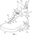
- FIG. 1 is a preferred embodiment of article of footwear 100, also referred to simply as article 100, in the form of an athletic shoe.
- article 100 in the form of an athletic shoe.
- the following detailed description discusses a preferred embodiment, however, it should be kept in mind that the present invention could also take the form of any other kind of footwear, including, for example, skates, boots, ski boots, snowboarding boots, cycling shoes, formal shoes, slippers or any other kind of footwear.
- Article 100 preferably includes upper 102.
- Upper 102 includes entry hole 105 that allows a foot to enter upper 102.
- upper 102 also includes an interior cavity that is configured to receive the foot.
- entry hole 105 preferably provides access to the interior cavity.
- upper 102 may be associated with sole 104. In one embodiment, upper 102 is attached to sole 104. In some cases, upper 102 is connected to sole 104 by stitching or an adhesive. In other cases, upper 102 could be integrally formed with sole 104.
- sole 104 comprises a midsole.
- sole 104 could also include an insole that is configured to contact a foot.
- sole 104 could include an outsole that is configured to contact a ground surface.
- sole 104 may comprise a midsole as well as an outsole and an insole.
- sole 104 may be provided with provisions for increasing traction depending on the intended application of article of footwear 100.
- sole 104 may include a variety of tread patterns.
- sole 104 may include one or more cleats.
- sole 104 could include both a tread pattern as well as a plurality of cleats. It should be understood that these provisions are optional.
- sole 104 could have a generally smooth lower ground contacting surface.
- Upper 102 may have any design. In some embodiments, upper 102 may have the appearance of a low top sneaker. In other embodiments, upper 102 may have the appearance of a high top sneaker. In this exemplary embodiment, upper 102 may include a high ankle portion 132. In particular, upper 102 may include first extended portion 181 and second extended portion 182. In this embodiment, first extended portion 181 and second extended portion 182 have generally triangular shapes. In other embodiments, first extended portion 181 and second extended portion 182 could have another shape. Examples of other shapes include, but are not limited to, rounded shapes, rectangular shapes, polygonal shapes, regular shapes as well as irregular shapes. Using this configuration for ankle portion 132 may help provide upper 102 with additional support for an ankle.
- Article 100 may include provisions for tightening upper 102 around a foot.
- article 100 may be associated with laces, straps and/or fasteners for tightening upper 102 once a foot has been inserted into upper 102.
- article 100 may include laces, straps and/or fasteners that can be manually adjusted by a user.
- article 100 may include provisions for automatically adjusting laces, straps and/or other fasteners associated with upper 102. By using automatically adjusting laces, straps and/or other fasteners, upper 102 may be tightened around a foot with a minimal amount of effort from a user. Examples of automatic lacing systems are disclosed in the automatic lacing system case.
- upper 102 may include individual tightening systems associated with different portions of upper 102.
- upper 102 may include automatic lacing system 122 that is associated with arch portion 130 of upper 102.
- upper 102 may include automatic ankle cinching system 124 that is associated with ankle portion 132 of upper 102.
- automatic lacing system 122 and automatic ankle cinching system 124 may be configured to automatically tighten and/or loosen upper 102 around an arch of a foot and an ankle of a foot. In other cases, however, manual lacing systems and/or manual ankle cinching systems can be used.
- Automatic lacing system 122 preferably includes a plurality of straps.
- the term strap as used throughout this detailed description and in the claims refers to any device that can be used for tightening a portion of an article of footwear to a foot.
- a strap could have any shape.
- a strap could have a rectangular or ribbon-like shape.
- the term strap is not intended to be restricted to tightening devices with ribbon-like shapes.
- a strap could have a lace-like shape.
- automatic lacing system 122 could be associated with other types of fasteners. Examples of other fasteners that could be used with automatic lacing system 122 include, but are not limited to laces, cords and strings.
- a strap could be made of any material. Examples of materials that could be used include, but are not limited to, leather, natural fabric, synthetic fabric, metal, rubber, as well as other materials. In some embodiments, a strap could be any type of woven strap as well. In particular, a strap could be woven from any material known in the art for producing woven straps.
- automatic lacing system 122 can include any number of straps. In some embodiments, only a single strap may be provided. In other embodiments, multiple straps may be provided. In this embodiment, automatic lacing system 122 includes four straps, including first strap 111, second strap 112, third strap 113 and fourth strap 114. For clarity, first strap 111, second strap 112, third strap 113 and fourth strap 114 may be referred to collectively as strap set 115.
- strap set 115 is disposed beneath lacing gap 107 of upper 102.
- strap set 115 may be configured to adjust the size of lacing gap 107. As the size of lacing gap 107 is adjusted, the sidewall portions of upper 102 may move closer together or further apart. With this arrangement, as strap set 115 is adjusted, upper 102 can be opened and/or closed around the arch of a foot.
- strap set 115 may be arranged in any direction on upper 102.
- strap set 115 could extend in a generally longitudinal direction.
- strap set 115 may be arranged in a lateral direction with respect to upper 102.
- the term "lateral direction" as used in this detailed description and in the claims refers to a direction extending from a medial side of upper 102 to a lateral side of upper 102. In other words, the lateral direction preferably extends along the width of upper 102.
- strap set 115 may include any type of spacing between adjacent straps. In some embodiments, the spacing between adjacent straps could vary. In other embodiments, one or more straps may cross over, or intersect with, one another. In a preferred embodiment, the straps of strap set 115 may be substantially evenly spaced. In particular, the width between adjacent portions of two straps remains substantially constant. In other words, the straps may be approximately parallel at adjacent portions.
- automatic lacing system 122 is configured to tighten and/or loosen upper 102 at arch portion 130 in the current embodiment, in other embodiments, automatic lacing system 122 could be associated with another portion of upper 102.
- automatic lacing system 122 could be configured to tighten upper 102 at a side portion of upper 102.
- automatic lacing system 122 could be associated with a toe portion of upper 102.
- automatic lacing system 122 could be associated with a heel portion of upper 102.
- automatic lacing system 122 may include provisions for automatically moving strap set 115.
- automatic lacing system 122 may include a strap moving mechanism.
- the term "strap moving mechanism" as used throughout this detailed description and in the claims refers to any mechanism capable of providing motion to one or more straps without requiring work to be performed by the user. In other words, a strap moving mechanism allows straps to be automatically tightened and/or automatically loosened. Examples of strap moving mechanisms are disclosed in the automatic lacing system case.
- a strap moving mechanism can comprise a motor configured to drive one or more straps of a strap set. For purposes of clarity, no strap moving mechanism is illustrated in this embodiment. However, in some cases, one or more components of a strap moving mechanism can be included with article 100.
- Automatic ankle cinching system 124 may include at least one ankle strap. In some embodiments, automatic ankle cinching system 124 may include multiple ankle straps. In this exemplary embodiment, automatic ankle cinching system 124 includes ankle strap 150.
- Ankle strap 150 could be any type of strap, including any type of strap previously discussed with respect to the straps of automatic lacing system 122. In some embodiments, ankle strap 150 could be a similar type of strap to the straps of strap set 115. In other embodiments, ankle strap 150 could be a different type of strap from the straps of strap set 115.
- automatic ankle cinching system 124 also includes provisions for receiving a portion of ankle strap 150.
- automatic ankle cinching system 124 includes housing 160 that is configured to receive a portion of ankle strap 150.
- Housing 160 could be located anywhere on ankle portion 132 of upper 102. In some cases, housing 160 could be disposed on a side of ankle portion 132. In other cases, housing 160 could be disposed on at the front of ankle portion 132. In one embodiment, housing 160 may be disposed on a rear portion of ankle portion 132.
- automatic ankle cinching system 124 may include provisions for automatically moving ankle strap 150 between a tightened and loosened position.
- automatic ankle cinching system may include a strap moving mechanism.
- the term "strap moving mechanism" as used throughout this detailed description and in the claims refers to any mechanism capable of providing motion to one or more straps without requiring work to be performed by the user. In other words, a strap moving mechanism allows straps to be automatically tightened and/or automatically loosened. Examples of strap moving mechanisms are disclosed in the automatic lacing system case.
- a strap moving mechanism for an ankle strap can comprise a spring coil that is configured to automatically tighten the ankle strap, as discussed in the automatic lacing system case.
- no strap moving mechanism for automatic ankle cinching system 124 is illustrated in this embodiment. However, in some cases, one or more components of a strap moving mechanism for an ankle cinching system can be included with article 100.
- An article of footwear may include provisions for illuminating one or more portions of an article.
- portions of an article may be illuminated for decorative purposes.
- portions of an article may be illuminated for purposes of increased safety by facilitating greater visibility of an article during nighttime or low light conditions.
- portions of an article can be illuminated to signal the activation of one or more automated systems, such as an automatic lacing system.
- article 100 may include lighting system 200.
- Lighting system 200 may comprise a plurality of lighting devices.
- the term "lighting device” as used throughout this detailed description and in the claims refers to any device configured for illumination.
- different types of lighting devices can be used including, but not limited to, incandescent bulbs, light emitting diodes (LEDs), florescent lights, high intensity discharge lamps, as well as other types of devices.
- each lighting device may be associated with an illuminated state, also referred to as an "on" state of the device, and a non-illuminated state, also referred to as an "off' state of the device.
- the number of lighting devices comprising lighting system 200 can vary.
- lighting system 200 may comprise a single lighting device.
- lighting system 200 can comprise two or more lighting devices.
- lighting system 200 comprises three lighting devices, including first lighting device 202, second lighting device 204 and third lighting device 206.
- first lighting device 202 and second lighting device 204 are disposed on a lateral portion of article 100, in other embodiments article 100 could include additional lighting devices disposed on a medial portion of article 100.
- first lighting device 202 can be disposed on any portion of article 100.
- first lighting device 202 may be disposed on heel portion 210 of sole 104.
- first lighting device 202 may be disposed on a peripheral edge of heel portion 210. With this arrangement, first lighting device 202 may illuminate a portion of sole 104. In other cases, first lighting device 202 may be disposed on another portion of article 100.
- First lighting device 202 can comprise one or more distinct lighting portions.
- first lighting device 202 includes first light emitting portion 222 and second light emitting portion 224.
- first light emitting portion 222 and second light emitting portion 224 can have curved shapes.
- first light emitting portion 222 and second light emitting portion 224 can be approximately tear drop shaped.
- first light emitting portion 222 and second light emitting portion 224 can have any other type of shape, including, but not limited to, circular shapes, elliptical shapes, rectangular shapes, regular polygonal shapes as well as irregular shapes.
- First lighting 202 device can be any type of lighting device.
- first lighting device 202 can be a LED type lighting device.
- first lighting device 202 can be another type of lighting device, such as an electroluminescent panel (ELP).
- ELP electroluminescent panel
- first lighting device 202 can provide illumination to sole 104 without excessive power consumption or heating.
- second lighting device 204 may be disposed on any portion of article 100. In some cases, second lighting device 204 may be disposed on a lateral portion of upper 102. In particular, second lighting device 204 may be disposed above heel portion 210 of sole 104. In other cases, second lighting device 204 may be disposed on another portion of article 100.
- Second lighting device 204 may be any type of lighting device.
- second lighting device 204 may comprise a plurality of bulbs 230.
- plurality of bulbs 230 may comprise distinct LED bulbs.
- second lighting device 204 comprises three distinct rows of LED bulbs.
- each distinct row of plurality of bulbs 230 may be associated with three distinct colors.
- plurality of bulbs 230 can comprise a single color.
- third lighting device 206 may be disposed on any portion of article 100.
- third lighting device 206 may be disposed on ankle strap 150.
- third lighting device 206 may be disposed over lacing gap 107 when ankle strap 150 is in a closed or tightened position. With this arrangement, third lighting device 206 may be oriented in a direction towards a forefoot of article 100. Furthermore, this arrangement increases the visibility of third lighting device 206 since a user can simply look down at the front of an article to see third lighting device 206.
- Third lighting device 206 may be any type of lighting device. In some cases, third lighting device 206 may be a LED type device. In other cases, third lighting device 206 can comprise any other type of lighting device. In one embodiment, third lighting device 206 may include an indicia of some kind. Examples of indicia that could be used include graphics, text, numbers or other types of indicia. In this exemplary embodiment, third lighting device 206 comprises logo 250. This arrangement allows a manufacturer to decorate article 100 using a logo or some other type of indicia. In an alternative embodiment, for example, third lighting device 206 may include the numbers of players on a sports team.
- Article 100 may include provisions for operating one or more lighting devices.
- lighting system 200 can include components for powering one or more lighting devices.
- lighting system 200 can include components for controlling the illumination of one or more lighting devices.
- lighting system 200 can include components for powering and controlling one or more lighting devices.
- FIG. 2 illustrates a schematic view of an embodiment of lighting system 200.
- FIG. 3 illustrates an isometric view of article 100 including lighting system 200.
- article 100 is shown in phantom in FIG. 3 to illustrate the locations of various components of lighting system 200.
- lighting system 200 may include lighting electrical control unit 240, hereby referred to as lighting ECU 240.
- lighting ECU 240 may be any type of ECU.
- an ECU could be a central processing unit (CPU) of some kind.
- CPU central processing unit
- an ECU could be a simple circuit of some kind for receiving electrical inputs and providing an electrical output according to the inputs.
- lighting ECU 240 may be a printed circuit board.
- Lighting ECU 240 may include a number of ports that facilitate the input and output of information and power.
- the term "port" means any interface or shared boundary between two conductors. In some cases, ports can facilitate the insertion and removal of conductors. Examples of these types of ports include mechanical connectors. In other cases, ports are interfaces that generally do not provide easy insertion or removal. Examples of these types of ports include soldering or electron traces on circuit boards.
- lighting ECU 240 can include provisions for transferring information and/or power with one or more lighting devices.
- lighting ECU 240 can include first lighting device port 241, second lighting device port 242 and third lighting port 243 that are configured to transfer information and/or power to first lighting device 202, second lighting device 204 and third lighting device 206, respectively.
- lighting ECU 240 can control the operation of first lighting device 202, second lighting device 204 and third lighting device 206.
- lighting ECU 240 can turn each lighting device on or off, as well as provide power for operating each lighting device.
- Lighting ECU 240 can also include provisions for switching one or more lighting devices between an illuminated state and a non-illuminated state. In other words, lighting ECU 240 can include provisions for turning each lighting device on or off. In some embodiments, lighting ECU 240 can include provisions for manually operating one or more lighting devices. In other embodiments, lighting ECU 240 can include provisions for automatically operating one or more lighting devices. In still other embodiments, lighting ECU 240 can simultaneously include both manual and automatic provisions for operating one or more lighting devices.
- lighting ECU 240 can include manual switch port 260 that is configured to transfer and/or receive information from manual switch 262. Also, lighting ECU 240 can include pressure switch port 264 that is configured to transfer and/or receive information from pressure switch 266. Using manual switch 262 and/or pressure switch 266 allows for direct control of lighting system 200. Although the current embodiment includes two switches, in other embodiments, only a single switch may be used. In still other embodiments, no switches may be used. In still other embodiments, more than two switches may be used.
- one or more devices may be connected to lighting ECU 240 via removable connectors.
- a circuit connecting third lighting device 206 with third lighting device port 243 can include first plug 284 and first connector 283.
- first plug 284 may be a 2 pin plug.
- first connector 283 may be a 2 pin connector.
- a circuit connecting pressure switch 266 and lighting ECU 240 may include second plug 281 and second connector 282.
- second plug 281 can be a 2 pin plug.
- second connector 282 can be a 2 pin connector.
- any devices attached to lighting ECU 240 can comprise one or more removable connectors. In other embodiments, none of the circuits may include removable connectors.
- a lighting system can include provisions for communicating with the automatic fastening system.
- an automatic fastening system can comprise an automatic lacing system.
- an automatic fastening system can comprise an automatic ankle cinching system.
- an automatic fastening system can include both an automatic lacing system and an automatic ankle cinching system.
- lighting ECU 240 can include fastening system port 290 that is configured to transfer and/or receive information automatic fastening system 291.
- lighting ECU 240 can communicate with an automatic fastening system.
- a lighting system can be configured to turn on one or more lighting devices once an automatic fastening system has tightened an article to the foot of a user.
- a lighting system can be configured to turn off one or more lighting devices once an automatic fastening system has been loosened.
- automatic fastening system 291 is optional and may not be included in some embodiments.
- An article with a lighting system can also include provisions for powering the lighting system.
- lighting system 200 may be associated with an electrical power source of some kind.
- lighting system 200 could be associated with an external battery.
- lighting system 200 could include an internal battery.
- lighting system 200 may be configured to receive power from internal battery 286.
- Battery 286 could be any type of battery.
- battery 286 could be a disposable battery. Examples of different types of disposable batteries include, but are not limited to, zinc-carbon, zinc-chloride, alkaline, silver-oxide, lithium disulfide, lithium-thionyl chloride, mercury, zinc-air, thermal, water-activated, nickel oxyhydroxide, and paper batteries.
- battery 286 could be a rechargeable battery of some kind. Examples of rechargeable batteries include, but are not limited to nickelcadmium, nickel-metal hydride and rechargeable alkaline batteries.
- a lighting system can include provisions for charging the battery.
- lighting system 200 may include charging electrical control unit 294, hereby referred to as charging ECU 294.
- charging ECU 294 may be any type of ECU.
- an ECU could be a central processing unit (CPU) of some kind.
- CPU central processing unit
- an ECU could be a simple circuit of some kind for receiving electrical inputs and providing an electrical output according to the inputs.
- charging ECU 294 may be a printed circuit board.
- Charging ECU 294 may include a number of ports that facilitate the input and output of information and power.
- the term "port" means any interface or shared boundary between two conductors. In some cases, ports can facilitate the insertion and removal of conductors. Examples of these types of ports include mechanical connectors. In other cases, ports are interfaces that generally do not provide easy insertion or removal. Examples of these types of ports include soldering or electron traces on circuit boards.
- charging ECU 294 can include battery port 296 that is configured to transfer power to and from battery 286. Additionally, charging ECU 294 can include charging port 298 that is configured to transfer power to and from a charging device. Any known charging device in the art could be used. Examples of different types of charging devices include, but are not limited to, simple chargers, trickle chargers, timer-based chargers, intelligent chargers, fast chargers, pulse chargers, USB-type chargers, inductive chargers, as well as other types of charging devices.
- an article of footwear can be associated with an inductive charging system. Since articles of footwear are typically worn in various conditions, including wet conditions, this inductive charging arrangement can help protect the charging circuit from exposure to the elements. In particular, because inductive charging systems do not require exposed electrodes, this arrangement can help prevent short circuiting and/or rusting that might otherwise occur with exposure to water.
- charging port 298 can be connected to internal charging coil 299.
- internal charging coil 299 may be part of a pair of inductive charging coils.
- the two coils can be coupled to transfer power, via induction, to battery 286. Details of one embodiment of an induction charging system are discussed later in the detailed description.
- charging ECU 294 can also be connected to lighting ECU 240 using first ECU port 295 and second ECU port 297.
- first ECU port 295 and second ECU port 297 can be used to transfer power and/or information between charging ECU 294 and lighting ECU 240.
- the current embodiment includes two different ECUs for a lighting system and for a charging system, other embodiments may only include a single ECU.
- charging ECU 294 and lighting ECU 240 can be combined into a single ECU that controls a charging system and a lighting system of an article of footwear.
- charging ECU 294 and lighting ECU 240 are disposed in sole 104. In other embodiments, however, charging ECU 294 and lighting ECU 240 could be disposed in another portion of article 100. For example, in another exemplary embodiment, charging ECU 294 and/or lighting ECU 240 could be disposed in housing 160, which is disposed in ankle portion 132 of upper 102.
- the locations of various components comprising a lighting system can vary. In some cases, some components can be disposed in an upper of an article. In other cases, some components can be disposed in a sole of an article. In an exemplary embodiment, some of the components of a lighting system are disposed on an upper and some of the components are disposed on a sole.
- FIG. 3 illustrates an exemplary embodiment of article 100, including some of the components of lighting system 200.
- each of the components of lighting system 200 is shown schematically.
- article 100 is shown in phantom in order to reveal the internal structure of article 100.
- the locations of the components shown in this embodiment are only intended to be exemplary. In other embodiments, the locations of one or more components can be changed. Also, the orientations of each component can vary from one embodiment to another.
- first lighting device 202 can be disposed on sole 104.
- second lighting device 204 and third lighting device 206 can be disposed on upper 102.
- third lighting device 206 can be disposed on ankle strap 150 of upper 102.
- manual switch 262 can be disposed on upper 102.
- manual switch 262 may be disposed on an ankle region of upper 102.
- the locations of one or more of these components can vary.
- manual switch 262 can be disposed on any other portion of upper 102 or of sole 104.
- manual switch 262 could be disposed on the heel of upper 102.
- an article can include provisions for protecting one or more components of a lighting system from direct exposure to the elements. Additionally, an article can include provisions for reducing direct contact between the components of a lighting system and a foot.
- one or more components of lighting system 200 can be disposed within sole 104.
- lighting ECU 240, charging ECU 294, battery 286, and internal charging coil 298 are disposed within sole 104.
- sole 104 may be a hollow sole with a large internal cavity configured to receive a plurality of components.
- sole 104 can be configured with one or more cavities or recesses that correspond to each individual component.
- a plurality of components of lighting system 200 could be embedded in a matrix material disposed within a larger cavity of sole 104.
- an internal cavity of sole 104 could be filled with foam that surrounds each of the various components.
- the current embodiment illustrates various components of lighting system 200 arranged in a substantially similar plane of sole 104. In other embodiments, however, one or more components could be stacked in a substantially vertical direction within sole 104. For example, in another exemplary embodiment lighting ECU 240 can be stacked over charging ECU 294 in a substantially vertical direction to provide a more compact arrangement within sole 104.
- pressure switch 266 can vary. In some cases, pressure switch 266 can be disposed on a portion of upper 102. In other cases, pressure switch 266 can be disposed in a portion of sole 104. In an exemplary embodiment, pressure switch 266 can be disposed on a top surface of sole 104. In particular, button 267 can be configured to extend outwards from top surface 105 of sole 104. In some cases, pressure switch 266 can be disposed within a forefoot portion of sole 104. In other cases, pressure switch 266 can be disposed in an arch portion or a heel portion of sole 104. With this arrangement, button 267 can be depressed as a foot is inserted into article 100.
- article 100 is shown in the current embodiment without an insole.
- article 100 can include an insole disposed between upper 102 and sole 104.
- the insole can rest on top surface 105 of sole 104.
- the insole may rest over the pressure switch. In these embodiments, as a foot is inserted into upper 102, the insole may be pushed downwards, which may cause the pressure switch to depress.
- Lighting system 200 can include provisions for protecting wires used to connect components disposed on upper 102 with components disposed on sole 104.
- third lighting device 206 can be connected to lighting ECU 240 via first wire 301.
- first wire 301 may further comprise first end portion 311 that extends through a portion of ankle strap 150.
- first end portion 311 may be threaded through a portion of ankle strap 150.
- first wire 301 may comprise second end portion 312 that extends through a portion of upper 102.
- second end portion 312 may be threaded through a portion of upper 102.
- second end portion 312 can be disposed between an inner and outer lining of upper 102.
- first wire 301 may comprise intermediate portion 313, which extends between first end portion 311 and second end portion 312.
- intermediate portion 313 may be disposed in a portion of housing 160.
- first wire 301 may be configured to move with ankle strap 150.
- first wire 301 may comprise a substantially flexible material that can be stretched and/or contracted as third lighting device 206 moves with ankle strap 150.
- first wire 301 may be configured with some slack to allow for motion of third lighting device 206.
- the remaining components of lighting system 200 can also be connected via one or more wires.
- one or more components may be connected to lighting ECU by connecting wires to the various ports of ECU 240 that have been previously discussed, and which are illustrated in FIG. 2 .
- second lighting component 204 can be connected to lighting ECU 240 via second wire 302.
- second wire 302 can be embedded in a lining of upper 102.
- manual switch 266 can be connected to lighting ECU 240 via third wire 303.
- third wire 303 can be embedded in a lining of upper 102. This arrangement helps provide protection for second wire 302 and third wire 303.
- the components of lighting system 200 are shown with a particular size in this embodiment. In other embodiments, however, the size of each component can vary.
- the size of battery 286 may vary.
- battery 286 could have a length in the range of 10 mm to 50 mm.
- battery 286 could have a width in the range of 10 mm to 50 mm.
- battery 286 has a width of about 30 mm.
- battery 286 preferably has a length of about 40 mm.
- the sizes of other components of lighting system 200 can vary from one embodiment to another.
- the current embodiment includes an inductive charging system
- other embodiments could include a plug-in type charging system.
- a USB-based charger may be used.
- article 100 can include a charging port that is electrically connected with a battery via an electrical circuit of some kind.
- the charging port may be configured to connect to an external battery charger of some kind.
- a charging system could be configured with both a physical charging port and an inductive loop that allows the system to operate in a plug-in type charging mode or an inductive-type charging mode.
- FIGS. 4 through 8 are intended to illustrate embodiments of article 100, including lighting system 200.
- lighting system 200 may be operated using a manual switch and/or a pressure switch.
- article 100 can be operated using a pressure switch in some embodiments.
- foot 402 may be disposed outside of article 100.
- pressure switch 266 may be in an "off' position.
- button 267 is fully extended above a top surface of sole 104. With pressure switch 266 in this off position, lighting system 200 may be deactivated.
- first lighting device 202, second lighting device 204 and third lighting device 206 may be in a non-illuminate state.
- buttons 267 may be depressed under the pressure of forefoot 404.
- pressure switch 266 may be disposed in an "on" position that is associated with the activation of lighting system 200.
- first lighting device 202, second lighting device 204 and third lighting device 206 may be in an illuminated state.
- a lighting system can be in communication with an automatic fastening system.
- one or more lighting devices may be controlled according to the operating conditions of an automatic fastening system.
- one or more lighting devices may be configured in a non-illuminated state when an automatic fastening system is disposed in a loosened position.
- one or more lighting devices may be configured in an illuminated state when an automatic fastening system is disposed in a tightened position.
- automatic lacing system 122 and automatic ankle cinching system 124 when pressure switch 266 is not depressed, automatic lacing system 122 and automatic ankle cinching system 124 may be in a loosened position, as seen in FIG. 4 .
- lighting system 200 may be disposed in a non-illuminated state when pressure switch 266 is not depressed.
- automatic lacing system 122 and automatic ankle cinching system 124 may move from a loosened position to a tightened position, as seen in FIGS. 4 and 5 .
- lighting system 200 is operated in an illuminated position when pressure switch 266 is depressed. In other words, this arrangement couples the operation of lighting system 200 with automatic lacing system 122 and automatic ankle cinching system 124.
- lighting system 200 can be used to indicate when one or more automatic fastening systems have been activated.
- a user can be made aware that automatic lacing system 122 and automatic ankle cinching system 124 have been activated by observing the illumination from first lighting device 202, second lighting device 204 and/or third lighting device 206.
- This arrangement can be useful in situations where the tightening of one or more automatic fastening systems is not easily observed by a user.
- the coupling of a lighting system and an automatic fastening system can be achieved in various ways.
- the lighting system may send control signals to the automatic fastening system so that the two systems operate in a cooperative manner.
- each system may be independently in communication with a switch, such as a pressure switch. In such cases, as the pressure switch is depressed, each system receives information from the pressure switch independently.
- a lighting system may not be coupled with an automatic fastening system.
- a lighting system and a fastening system may operated independently of one another.
- the coupling of a lighting system with an automatic fastening system could be reversed from the current embodiment.
- a lighting system could be configured to operate in an illuminated state when an automatic fastening system is in a loosened position and the lighting system could be configured to operate in a non-illuminated state when the automatic fastening system is in a tightened position.
- an article can be provided with a lighting system but not an automatic fastening system.
- the automatic fastening system may be optional.
- the lighting system may be optional.
- the current embodiment includes only pressure switch 266 and does not include a manual switch.
- article 100 can include both a pressure switch and a manual switch.
- a manual switch can be used to override signals transmitted using a pressure switch.
- a manual switch could be used to deactivate an illumination system even when a foot is inserted and a pressure switch is fully depressed.
- a manual switch could be used to activate an illumination system even when a foot is not inserted and a pressure switch is not depressed.
- article 100 can be operated using manual switch 262.
- foot 602 can be disposed within article 100.
- manual switch 262 may be disposed in an "off' position.
- lighting system 200 is deactivated so that first lighting device 202, second lighting device 204 and third lighting device 206 are not illuminated.
- user 704 may engage manual switch 262 so that manual switch 262 is disposed in an "on" position.
- lighting system 200 may be activated.
- first lighting device 202, second lighting device 204 and third lighting device 206 may be illuminated. With this arrangement, a user can have control over when lighting system 200 is activated or deactivated.
- a manual switch may be a button that can be depressed.
- any type of user controlled device can be used.
- the term "user controlled device” refers to any device that is configured to receive input directly from a user. Examples of other user controlled devices that may be used include but are not limited to, levers, switches, dials, consoles or other user controlled devices.
- manual switch 262 can be used to control lighting system 200 independently of the automatic fastening systems. In other embodiments, however, one or more automatic fastening systems could be simultaneously controlled using manual switch 262.
- automatic lacing system 122 and automatic ankle cinching system 124 can be configured to tighten and/or loosen strap set 115 and ankle strap 150, respectively, when manual switch 266 is depressed. With this arrangement, a user can control both a lighting system and an automatic fastening system using a manual switch.
- a lighting system could be configured to receive information from a heat sensor. In this case, as a foot is inserted into an upper, the heat sensor may transmit information to the lighting system to illuminate one or more lighting devices.
- a pair of footwear can be associated with a housing for storing the articles of footwear.
- the housing can include provisions for charging.
- the housing can provide components of the inductive charging system that allow power to be transferred from an external power source to the articles of footwear.
- FIGS. 8 through 12 illustrate footwear housing 800 for a pair of footwear.
- footwear housing 800 is illustrated with a particular design.
- footwear housing 800 is illustrated as a footwear bag which resembles a traditional duffle-type bag.
- footwear housing 800 has a size that is configured to fit a single pair of footwear.
- footwear housing 800 could have any other design.
- footwear housing 800 could have another shape and/or size in other embodiments. Examples of other designs for a footwear housing include, but are not limited to, any type of bags and/or back packs.
- the footwear housing could including any provisions for carrying the housing, including any type of strap or handle.
- footwear housing 800 includes base portion 801. Furthermore, footwear housing 800 may include first panel 802 and second panel 804. In some cases, first panel 802 and second panel 804 may be movable panels that are configured to open in order to provide access to the interior of footwear housing 800. In one embodiment, first panel 802 and second panel 804 may be adjusted using handle 808. In some embodiments, handle 808 can include provisions for temporarily locking first panel 802 and second panel 804 in a closed position.
- footwear housing 800 can include provisions for indicating the status of a charging system associated with footwear housing 800.
- footwear housing 800 can include a visual indicator, such as a light, for indicating the charging status.
- footwear housing 800 can include a sound-based indicator, such as a speaker configured to produce a sound to indicate the charging status.
- footwear housing 800 can include charging indicator light 899.
- charging indicator light 899 may be an LED light that is lit to indicate the charging status of an article of footwear.
- footwear housing 800 may include interior portion 900 that is configured to receive one or more articles of footwear.
- footwear housing 800 also includes floor portion 902 that provides a floor for interior portion 900.
- floor portion 902 may be rounded.
- floor portion 902 may be substantially flat. With this arrangement, articles placed within footwear housing 800 may rest upon floor portion 902 in a stable manner.
- Footwear housing 800 can include one or more components of a charging system.
- footwear housing 800 can include charging station 906.
- charging station 906 may include provisions for transferring power to one or more articles of footwear.
- charging station 906 can include charging station ECU 908.
- charging station ECU may be any type of ECU.
- an ECU could be a central processing unit (CPU) of some kind.
- CPU central processing unit
- an ECU could be a simple circuit of some kind for receiving electrical inputs and providing an electrical output according to the inputs.
- charging station ECU 908 may be a printed circuit board.
- Charging station ECU 908 may include a number of ports that facilitate the input and output of information and power.
- the term "port" means any interface or shared boundary between two conductors. In some cases, ports can facilitate the insertion and removal of conductors. Examples of these types of ports include mechanical connectors. In other cases, ports are interfaces that generally do not provide easy insertion or removal. Examples of these types of ports include soldering or electron traces on circuit boards.
- charging station ECU 908 can include first port 910 that is configured to transfer power to first external inductive loop 912. Likewise, in some cases, charging station ECU 908 can include second port 911 that is configured to transfer power to second external inductive loop 914. In some cases, each external inductive loop may be associated with an internal inductive loop of a corresponding article of footwear.
- Charging station 906 can also include provisions for receiving power from an external power source of some kind.
- charging station ECU 908 can include third port 913 that is configured to receive power from an external power source.
- third port 913 can be associated with power cord 916 that can be plugged into a wall socket.
- first panel 802 and second panel 804 of footwear housing 800 have been opened to reveal interior portion 900.
- components of charging station 906 may be disposed below floor portion 902. With this arrangement, the components of charging station 906 can be protected from the elements and from various types of contact with one or more articles of footwear. In other embodiments, however, one or more portions of charging station 906 may be exposed within interior portion 900.
- footwear pair 1000 is inserted into footwear housing 800, as seen in FIGS. 10 and 11 .
- Footwear pair 1000 may comprise first article 1002 and second article 1004.
- floor portion 902 can include one or more locating features to facilitate alignment of footwear pair 1000 with charging station 906.
- it may be necessary to ensure proper alignment of internal inductive loops disposed within each article with external inductive loops disposed in footwear housing 800.
- floor portion 902 includes first recessed portion 1010 and second recessed portion 1012 that correspond with first article 1002 and second article 1004, respectively.
- first recessed portion 1010 and second recessed portion 1012 may be shaped to fit the bottom surfaces of first article 1002 and second article 1004, respectively. This arrangement can help ensure proper alignment between footwear pair 1000 and charging station 906, which can facilitate efficient charging.
- floor portion 902 can be configured with recesses that engage protrusions located on bottom surfaces of first article 1002 and second article 1004. In other cases, floor portion 902 can be configured with protrusions that engage recesses located on bottom surfaces of first article 1002 and second article 1004. In still other embodiments, other types of locating features that are known in the art can be used.
- FIGS. 12 and 13 illustrate additional embodiments of provisions for ensuring proper alignment between a pair of footwear and a charging station.
- footwear housing 800 can include adjustable bindings 1300.
- adjustable bindings 1300 may include first adjustable binding 1302 and second adjustable binding 1304.
- first adjustable binding 1302 includes toe member 1310 and heel member 1312.
- Heel member 1312 may be fixed in place with respect to floor portion 902.
- toe member 1310 may be configured to slide in a longitudinal direction with respect to floor portion 902.
- heel portion 1320 of first article 1322 may confront heel member 1312.
- toe member 1310 may be adjusted to confront toe portion 1323.
- toe member 1310 and heel member 1312 may help maintain first article 1322 in a predetermined location with respect to floor portion 902.
- first article 1322 may be positioned in a manner that orients internal inductive loop 1340 of first article 1322 with external inductive loop 1342 of a charging system.
- second adjustable binding 1304 may be used to locate and fix second article 1324.
- article 1360 may include first locating recess 1361 and second locating recess 1362.
- floor portion 902 may include first locating protrusion 1371 and second locating protrusion 1372.
- First locating recess 1361 may be configured to receive first locating protrusion 1371
- second locating recess 1362 may be configured to receive second locating protrusion 1372.
- article 1362 can be located and oriented in a manner that ensures proper alignment between internal inductive loop 1381 of article 1360 and external inductive loop 1382 of a charging system.
- floor portion 902 may include additional locating protrusions configured to insert into recesses in a second article of footwear to facilitate charging of a pair of footwear.
- the current embodiment includes an external inductive loop disposed in a floor portion of a footwear housing
- other embodiments can include external inductive loops disposed in other portions of the footwear housing.
- one or more external inductive loops can be disposed on interior side walls of the footwear housing.
- an internal inductive loop could be disposed in any other portion of an article of footwear. Examples of other portions that could house an internal inductive loop include, but are not limited to, a tongue, an upper sidewall, a forefoot portion of an upper, a heel portion of an upper, as well as any other portion of an article of footwear.
- the location of an internal inductive loop in an article of footwear can be selected according to the location of an external inductive loop in a footwear housing so that the internal inductive loop can be disposed adjacent to the external inductive loop when the article is inserted into the footwear housing.
- FIG. 14 illustrates a top down view of footwear housing 800 with footwear pair 1000 inserted.
- first internal inductive loop 1202 of first article 1002 may be aligned with first external inductive loop 912.
- second internal inductive loop 1204 of second article 1004 may be aligned with second external inductive loop 914.
- electricity received at an external power source can be transferred to charging station ECU 908 via power cord 916.
- the electricity can then be transferred to first external inductive loop 912.
- an external power source with an alternating current power can be inductively transferred between first external inductive loop 912 and first internal inductive loop 1202.
- an alternating magnetic field can be created at first external inductive loop 912, which induces a current in first internal inductive loop 1202.
- a rechargeable power source such as a battery, disposed within first article 1002, which can provide power for a lighting system and/or an automatic fastening system.
- electricity received at charging station ECU 908 can be transferred to second external inductive loop 914.
- an external power source with an alternating current
- power can be inductively transferred between second external inductive loop 914 and second internal inductive loop 1204.
- an alternating magnetic field can be created at second external inductive loop 914, which induces a current in second internal inductive loop 1204.
- a rechargeable power source such as a battery, disposed within second article 1004, which can provide power for a lighting system and/or an automatic fastening system.
- the charging system discussed in this detailed description and in the claims can be used independently of a lighting system.
- the charging system discussed in this detailed description is used to charge a battery of some kind, that battery can be further coupled to one or more different electrical systems.
- the charging system discussed in this detailed description and in the claims may be used to power any type of electrical system associated with an article of footwear.
- the charging system discussed in this embodiment could be used to charge a battery to power an accelerometer for tracking distance and motion.
- the charging system discussed here could be used to power a heating and/or cooling system for an article.
- the charging system could be used to power two or more electrical systems simultaneously.
Landscapes
- Engineering & Computer Science (AREA)
- Power Engineering (AREA)
- Computer Networks & Wireless Communication (AREA)
- Microelectronics & Electronic Packaging (AREA)
- Footwear And Its Accessory, Manufacturing Method And Apparatuses (AREA)
- Charge And Discharge Circuits For Batteries Or The Like (AREA)
- Secondary Cells (AREA)
Claims (15)
- Système de charge pour article chaussant, comprenant :une source d'énergie rechargeable (286) disposée à l'intérieur de l'article chaussant (100), la source d'énergie rechargeable (286) étant configurée pour alimenter un système d'éclairage ;un boîtier d'article chaussant (800) ayant un premier panneau mobile (802) et un second panneau mobile configurés pour s'ouvrir afin de permettre l'accès à l'intérieur du boîtier d'article chaussant (800) configuré pour recevoir l'article chaussant (100), le boîtier d'article chaussant (800) ayant en outre une partie intérieure (900) munie d'une partie de sol (902), le boîtier d'article chaussant (800) étant associé à une source d'énergie externe ;une boucle inductive interne (299) disposée à l'intérieur de l'article chaussant (100), la boucle inductive interne (299) étant configurée pour transférer de l'énergie vers la source d'énergie rechargeable (286) ;une boucle inductive externe (912, 914) disposée à l'intérieur du boîtier d'article chaussant (800), la boucle inductive externe (912, 914) étant configurée pour recevoir de l'énergie de la part de la source d'énergie externe ; etdans lequel la boucle inductive interne (299) et la boucle inductive externe (912, 914) sont reliées par induction lorsque l'article chaussant (100) est disposé à l'intérieur du boîtier d'article chaussant (800) posé sur la partie des sol (902).
- Système de charge selon la revendication 1, dans lequel la boucle inductive externe (912, 914) est configurée pour générer un champ magnétique alternatif, et dans lequel, en particulier, le champ magnétique alternatif généré par la boucle inductive externe (912, 914) crée un courant alternatif dans la boucle inductive interne (299).
- Système de charge selon la revendication 2, dans lequel le courant généré dans la boucle inductive interne (299) est utilisé pour charger la source d'énergie rechargeable (286) dans l'article chaussant (100).
- Système de charge selon la revendication 3, dans lequel la source d'énergie rechargeable (286) est chargée lorsque l'article chaussant (100) est disposé à l'intérieur du boîtier d'article chaussant (800) d'une manière qui aligne la boucle inductive interne (299) avec la boucle inductive externe (912, 914).
- Système de charge selon la revendication 4, dans lequel le boîtier d'article chaussant (800) peut être utilisé pour recharger une paire d'articles chaussants (100) simultanément à l'aide d'une paire de boucles inductives externes (912, 914) qui peuvent être reliées à des boucles inductives internes correspondantes (299) dans la paire d'articles chaussants (100).
- Système de charge selon la revendication 5, dans lequel la source d'énergie rechargeable (286) peut être utilisée pour alimenter un système de fixation automatique (291).
- Boîtier d'article chaussant (800) destiné à un article chaussant, comprenant :un premier panneau mobile (802) et un second panneau mobile (804) configurés pour s'ouvrir afin de permettre l'accès à l'intérieur du boîtier d'article chaussant (800) ;une partie intérieure (900) qui est configurée pour recevoir l'article chaussant (100), la partie intérieure (900) ayant une partie de sol (902) destinée aux articles chaussants reçus dans le boîtier d'article chaussant qui sont posés dessus ;une station de charge ECU (908) associée à la partie intérieure (900) et configurée pour recevoir de l'énergie de la part d'une source d'énergie externe ;une boucle inductive externe (912, 914) en communication avec la station de charge ECU (908) ; etdans lequel la boucle inductive externe (912, 914) est associée à une boucle inductive interne (299) de l'article chaussant (100).
- Boîtier d'article chaussant selon la revendication 7, dans lequel la partie intérieure (900) comprend une pièce de positionnement (1010, 1012 ; 1302, 1304) configurée pour faciliter l'alignement de l'article chaussant (100) sur la partie de sol (902) de la partie intérieure (900), et dans lequel, en particulier, la pièce de positionnement facilite l'alignement de la boucle inductive externe (912, 914) avec la boucle inductive interne (299) de l'article chaussant (100) d'une manière qui facilite le couplage inductif de l'article chaussant (100) avec le boîtier d'article chaussant (800).
- Boîtier d'article chaussant selon la revendication 8, dans lequel la pièce de positionnement (1010, 1012 ; 1302, 1304) facilite l'alignement de la boucle inductive externe (912, 914) avec la boucle inductive interne (299) de l'article chaussant (100) d'une manière qui facilite le couplage inductif de l'article chaussant (100) avec le boîtier d'article chaussant (800), et dans lequel la boucle inductive externe (912, 914) est disposée sous la partie de sol (902), et dans lequel, en particulier, la station de charge ECU (908) est disposée sous la partie de sol (902) et/ou la boucle inductive externe (912, 914) est espacée d'une surface inférieure de l'article chaussant (100).
- Système de charge selon la revendication 9, dans lequel la boucle inductive externe (912, 914) est espacée d'une surface inférieure de l'article chaussant (100), et dans lequel le boîtier d'article chaussant (800) comprend la première partie de panneau (802) et une seconde partie de panneau (804) qui permettent l'accès à la partie intérieure (900).
- Système de charge selon la revendication 10, dans lequel la première partie de panneau (802) et la seconde partie de panneau (804) peuvent être fermées, et dans lequel, en particulier, le boîtier d'article chaussant (800) peut être utilisé pour transporter l'article chaussant (100).
- Procédé de charge d'un article chaussant, à l'aide du système de charge selon la revendication 1, comprenant les étapes de :raccordement d'un boîtier d'article chaussant (800) selon la revendication 7 à une source d'énergie externe, le boîtier d'article chaussant (800) comprenant une station de charge (306) avec une boucle inductive externe (912, 914), le boîtier d'article chaussant (800) ayant un premier panneau mobile (802) et un second panneau mobile (804) configurés pour s'ouvrir afin de permettre l'accès à l'intérieur du boîtier d'article chaussant (800) ;association de l'article chaussant (100) comprenant une boucle inductive interne (299) au boîtier d'article chaussant (800), la boucle inductive interne (299) étant configurée pour transférer de l'énergie vers une source d'énergie rechargeable (286) dans l'article chaussant (100) ;alignement de l'article chaussant (100) dans le boîtier d'article chaussant (800) d'une manière qui couple par induction la boucle inductive interne (299) avec la boucle inductive externe (912, 914) ; etde chargement de la source d'énergie rechargeable (286).
- Procédé selon la revendication 12, dans lequel la source d'énergie rechargeable (286) est configurée pour fournir de l'énergie à un système d'éclairage de l'article chaussant (100).
- Procédé selon l'une des revendications 12 ou 13, dans lequel l'étape d'alignement de l'article chaussant (100) avec le boîtier d'article chaussant (800) comprend une étape d'utilisation d'au moins une pièce de positionnement (1010, 2012 ; 1302, 1304) disposée dans le boîtier d'article chaussant (800).
- Procédé selon l'une quelconque des revendications 12 à 14, dans lequel l'étape d'association du boîtier d'article chaussant (800) avec une source d'énergie externe comprend une étape de branchement d'un câble (916) sur une prise murale.
Applications Claiming Priority (3)
| Application Number | Priority Date | Filing Date | Title |
|---|---|---|---|
| US12/114,022 US8046937B2 (en) | 2008-05-02 | 2008-05-02 | Automatic lacing system |
| US12/369,410 US8058837B2 (en) | 2008-05-02 | 2009-02-11 | Charging system for an article of footwear |
| PCT/US2009/042081 WO2009134864A2 (fr) | 2008-05-02 | 2009-04-29 | Système de charge pour article chaussant |
Publications (3)
| Publication Number | Publication Date |
|---|---|
| EP2278897A2 EP2278897A2 (fr) | 2011-02-02 |
| EP2278897A4 EP2278897A4 (fr) | 2014-03-19 |
| EP2278897B1 true EP2278897B1 (fr) | 2018-05-23 |
Family
ID=41255748
Family Applications (1)
| Application Number | Title | Priority Date | Filing Date |
|---|---|---|---|
| EP09739666.7A Active EP2278897B1 (fr) | 2008-05-02 | 2009-04-29 | Système de charge pour article chaussant |
Country Status (5)
| Country | Link |
|---|---|
| US (1) | US8058837B2 (fr) |
| EP (1) | EP2278897B1 (fr) |
| JP (1) | JP5421359B2 (fr) |
| CN (1) | CN102316758B (fr) |
| WO (1) | WO2009134864A2 (fr) |
Cited By (5)
| Publication number | Priority date | Publication date | Assignee | Title |
|---|---|---|---|---|
| US10477911B2 (en) | 2008-05-02 | 2019-11-19 | Nike, Inc. | Article of footwear and charging system |
| US10918164B2 (en) | 2008-05-02 | 2021-02-16 | Nike, Inc. | Lacing system with guide elements |
| US11206891B2 (en) | 2008-05-02 | 2021-12-28 | Nike, Inc. | Article of footwear and a method of assembly of the article of footwear |
| US11533967B2 (en) | 2008-05-02 | 2022-12-27 | Nike, Inc. | Automatic lacing system |
| US11723436B2 (en) | 2008-05-02 | 2023-08-15 | Nike, Inc. | Article of footwear and charging system |
Families Citing this family (59)
| Publication number | Priority date | Publication date | Assignee | Title |
|---|---|---|---|---|
| CN101193568B (zh) | 2004-10-29 | 2011-11-30 | 博技术有限公司 | 基于卷轴的闭合系统及使用该系统的鞋类物品 |
| JP2011030294A (ja) * | 2009-07-22 | 2011-02-10 | Sony Corp | 二次電池装置 |
| KR20110118963A (ko) * | 2010-04-26 | 2011-11-02 | 한국생산기술연구원 | 비접촉 충전 발열 장치 |
| JP2012044827A (ja) * | 2010-08-23 | 2012-03-01 | Midori Anzen Co Ltd | 非接触充電装置 |
| US8935860B2 (en) * | 2011-10-28 | 2015-01-20 | George Torres | Self-tightening shoe |
| KR101315540B1 (ko) * | 2012-01-20 | 2013-10-08 | 김병엽 | 무선충전이 가능한 난방용 실내화 및 난방용 실내화의 무선충전 장치 |
| ITVR20120084A1 (it) * | 2012-05-04 | 2013-11-05 | Vibram Spa | Suola per calzature dotata di dispositivo luminoso e metodo per attivare/disattivare detto dispositivo luminoso. |
| US9220315B2 (en) * | 2012-08-29 | 2015-12-29 | Nike, Inc. | Article of footwear with an indicator for a heating system |
| US8728530B1 (en) | 2012-10-30 | 2014-05-20 | The Clorox Company | Anionic micelles with cationic polymeric counterions compositions thereof |
| US8883706B2 (en) | 2012-10-30 | 2014-11-11 | The Clorox Company | Anionic micelles with cationic polymeric counterions systems thereof |
| US8728454B1 (en) | 2012-10-30 | 2014-05-20 | The Clorox Company | Cationic micelles with anionic polymeric counterions compositions thereof |
| US8765114B2 (en) | 2012-10-30 | 2014-07-01 | The Clorox Company | Anionic micelles with cationic polymeric counterions methods thereof |
| US8883705B2 (en) | 2012-10-30 | 2014-11-11 | The Clorox Company | Cationic micelles with anionic polymeric counterions systems thereof |
| US9118188B2 (en) * | 2012-12-17 | 2015-08-25 | Intel Corporation | Wireless charging system |
| WO2014138297A1 (fr) * | 2013-03-05 | 2014-09-12 | Boa Technology Inc. | Systèmes, procédés et dispositifs de fermeture automatique de dispositifs médicaux |
| US10251451B2 (en) | 2013-03-05 | 2019-04-09 | Boa Technology Inc. | Closure devices including incremental release mechanisms and methods therefor |
| US20140327320A1 (en) * | 2013-05-01 | 2014-11-06 | Witricity Corporation | Wireless energy transfer |
| EP3653073B1 (fr) | 2013-07-10 | 2023-01-11 | Boa Technology Inc. | Dispositifs de fermeture comprenant des mécanismes de relâchement incrémentiels |
| US20150237949A1 (en) * | 2014-02-25 | 2015-08-27 | Efthimios Poulos | Safety boots with multi level safety features |
| US10478723B2 (en) | 2014-06-30 | 2019-11-19 | Microsoft Technology Licensing, Llc | Track based play systems |
| US10537821B2 (en) | 2014-06-30 | 2020-01-21 | Microsoft Technology Licensing, Llc | Interactive play sets |
| US10518188B2 (en) | 2014-06-30 | 2019-12-31 | Microsoft Technology Licensing, Llc | Controlling physical toys using a physics engine |
| US20160058127A1 (en) | 2014-08-28 | 2016-03-03 | Boa Technology Inc. | Devices and methods for enhancing the fit of boots and other footwear |
| US9919226B2 (en) | 2014-10-08 | 2018-03-20 | Microsoft Technology Licensing, Llc | Storage and charging device for game pieces |
| US10369477B2 (en) | 2014-10-08 | 2019-08-06 | Microsoft Technology Licensing, Llc | Management of resources within a virtual world |
| US9696757B2 (en) | 2014-10-08 | 2017-07-04 | Microsoft Corporation | Transfer of attributes between generations of characters |
| JP2016131752A (ja) * | 2015-01-20 | 2016-07-25 | 株式会社エクスプロア | 表示部を有する靴 |
| US9894954B2 (en) | 2015-05-28 | 2018-02-20 | Nike, Inc. | Sole plate for an article of footwear |
| US10292451B2 (en) | 2015-05-28 | 2019-05-21 | Nike, Inc. | Sole plate for an article of footwear |
| US10070681B2 (en) | 2015-05-28 | 2018-09-11 | Nike, Inc. | Control device for an article of footwear |
| US10743620B2 (en) | 2015-05-28 | 2020-08-18 | Nike, Inc. | Automated tensioning system for an article of footwear |
| US10010129B2 (en) | 2015-05-28 | 2018-07-03 | Nike, Inc. | Lockout feature for a control device |
| US10231505B2 (en) * | 2015-05-28 | 2019-03-19 | Nike, Inc. | Article of footwear and a charging system for an article of footwear |
| US10944282B2 (en) | 2015-05-28 | 2021-03-09 | Nike, Inc. | Transportation apparatus with NFC charger |
| JP2017012573A (ja) * | 2015-07-03 | 2017-01-19 | 哲美 原川 | 歩行情報取得機能付履物及び安全管理システム |
| US11185130B2 (en) | 2015-10-07 | 2021-11-30 | Puma SE | Article of footwear having an automatic lacing system |
| WO2018095501A1 (fr) | 2016-11-22 | 2018-05-31 | Puma SE | Procédé pour lacer une chaussure, en particulier une chaussure de sport, et chaussure, en particulier chaussure de sport |
| US11103030B2 (en) | 2015-10-07 | 2021-08-31 | Puma SE | Article of footwear having an automatic lacing system |
| US11033079B2 (en) | 2015-10-07 | 2021-06-15 | Puma SE | Article of footwear having an automatic lacing system |
| US10139090B2 (en) | 2015-11-02 | 2018-11-27 | Joseph Goodrich | Rechargeable illuminating shoes |
| WO2017092775A1 (fr) | 2015-12-02 | 2017-06-08 | Puma SE | Procédé pour le laçage d'une chaussure, en particulier d'une chaussure de sport |
| JP6701321B2 (ja) * | 2016-02-19 | 2020-05-27 | Cyberdyne株式会社 | 装着式歩容検知装置、歩行能力改善システム及び装着式歩容検知システム |
| US10674793B2 (en) | 2016-03-15 | 2020-06-09 | Nike, Inc. | Actuator for an automated footwear platform |
| KR20230106736A (ko) | 2016-08-02 | 2023-07-13 | 보아 테크놀러지, 인크. | 신발끈 결속 시스템의 인장 부재 가이드 |
| RU2715263C1 (ru) | 2016-11-22 | 2020-02-26 | Пума Се | Способ надевания или снятия предмета одежды на его носчика или с его носчика или способ закрывания, надевания, открывания или снятия носимого человеком предмета багажа |
| US11122851B2 (en) | 2017-01-03 | 2021-09-21 | The Winger Group, LLC | Shoes with shape shifting orthotic soles |
| US11357279B2 (en) | 2017-05-09 | 2022-06-14 | Boa Technology Inc. | Closure components for a helmet layer and methods for installing same |
| EP3629884A1 (fr) | 2017-05-31 | 2020-04-08 | Nike Innovate C.V. | Chaise de sport avec intégration de jeu |
| US10651673B2 (en) * | 2017-10-19 | 2020-05-12 | Hollowick Inc. | Flameless candle, magnetic resonance charging system, and associated methods |
| TWI632874B (zh) * | 2017-11-24 | 2018-08-21 | 沅聖科技股份有限公司 | 智慧鞋墊模組 |
| US10178890B1 (en) | 2018-05-31 | 2019-01-15 | Nike, Inc. | Intelligent electronic footwear and control logic for executing automated footwear features |
| USD899053S1 (en) | 2019-01-30 | 2020-10-20 | Puma SE | Shoe |
| USD889805S1 (en) | 2019-01-30 | 2020-07-14 | Puma SE | Shoe |
| USD906657S1 (en) | 2019-01-30 | 2021-01-05 | Puma SE | Shoe tensioning device |
| US11464286B2 (en) * | 2019-03-20 | 2022-10-11 | Dennis George Jacob | Internet connected adjustable structural support and cushioning system for footwear |
| US11484089B2 (en) | 2019-10-21 | 2022-11-01 | Puma SE | Article of footwear having an automatic lacing system with integrated sound damping |
| JP1696584S (fr) * | 2020-10-15 | 2021-10-04 | ||
| US11700904B2 (en) | 2021-11-12 | 2023-07-18 | Orpyx Medical Technologies Inc. | Wireless charging assemblies for sensorized insoles, methods for charging sensorized insoles, and footwear systems including sensorized insoles |
| CA3175982A1 (fr) | 2021-12-16 | 2023-06-16 | Orpyx Medical Technologies Inc. | Assemblages de recharge sans fil pour des semelles interieures a capteurs, methodes de recharge de ces semelles et systemes de chaussures comprenant ces semelles |
Family Cites Families (143)
| Publication number | Priority date | Publication date | Assignee | Title |
|---|---|---|---|---|
| US1184396A (en) * | 1914-05-20 | 1916-05-23 | John E Trimble | Electrically-illuminated shoe. |
| US3008038A (en) | 1959-07-29 | 1961-11-07 | Milton L Dickens | Shoe with electric bulb providing illumination |
| US3070907A (en) * | 1962-04-11 | 1963-01-01 | Rocco Joseph | Illuminated dancing shoe |
| US3946505A (en) * | 1974-07-31 | 1976-03-30 | Dana Alfred Iii | Shoe with detachable illuminated heel |
| US3893247A (en) * | 1974-07-31 | 1975-07-08 | Iii Alfred Dana | Illuminated soles and heels |
| US4020572A (en) * | 1976-02-17 | 1977-05-03 | Chiaramonte Jr Gasper | Illuminated footwear |
| US4112601A (en) * | 1977-03-23 | 1978-09-12 | Chiaramonte Jr Gasper | Dynamically illuminated footwear |
| US4130951A (en) | 1977-09-09 | 1978-12-26 | Aaron Powell | Illuminated dancing shoes |
| US4158922B1 (en) * | 1978-03-27 | 1995-03-14 | Gear L A Inc | Flashing discoshoes |
| US4253253A (en) * | 1979-05-29 | 1981-03-03 | Mccormick Arnold J | Ornamental shoe heel device |
| US4426796A (en) * | 1980-01-04 | 1984-01-24 | Spademan Richard George | Sport shoe with a dynamic fitting system |
| IT1193578B (it) * | 1981-01-28 | 1988-07-08 | Nordica Spa | Dispositivo di chiusura particolarmente per scarponi da sci |
| FR2540359B1 (fr) | 1983-02-09 | 1987-07-10 | Salomon Sa | Chaussure de ski alpin a fermeture automatique |
| EP0121026A1 (fr) | 1983-03-30 | 1984-10-10 | Dana III, Alfred | Chaussure de sécurité à semelle molle |
| IT1180988B (it) | 1984-06-01 | 1987-09-23 | Caber Italia | Dispositivo di serraggio e regolazione particolarmente per scarponi da sci |
| JPS6270802U (fr) * | 1985-10-24 | 1987-05-06 | ||
| IT1186356B (it) * | 1985-11-04 | 1987-11-26 | Nordica Spa | Scarpone da sci con dispositivo di chiusura e con dispositivo di bloccaggio del piede ad azionamento elettrico |
| IT1186221B (it) * | 1985-12-02 | 1987-11-18 | Nordica Spa | Scarpone da sci con gruppo di azionamento dei dispositivi di chiusura e di regolazione |
| CH674124A5 (fr) * | 1987-12-22 | 1990-05-15 | Raichle Sportschuh Ag | |
| CA1253832A (fr) * | 1988-03-07 | 1989-05-09 | Nicholas A. Rodgers | Articles chaussants |
| US4999936A (en) * | 1988-04-24 | 1991-03-19 | Calamia Thomas J | Illuminated sign |
| US4895110A (en) * | 1988-06-22 | 1990-01-23 | Advance Designs And Concepts | Illuminated pet collar |
| FR2643794A1 (fr) | 1988-11-10 | 1990-09-07 | Darfeuille Jean | Chaussons ou chaussures possedant un dispositif specifique d'eclairage de nuit |
| US5500635A (en) * | 1990-02-20 | 1996-03-19 | Mott; Jonathan C. | Products incorporating piezoelectric material |
| EP0443363A1 (fr) | 1990-02-21 | 1991-08-28 | Raichle Sportschuh AG | Chaussure de sport, en particulier chaussure de ski |
| US5033212A (en) * | 1990-10-09 | 1991-07-23 | Evanyk Walter R | System for increasing the visibility of an object |
| IL99575A0 (en) | 1991-09-26 | 1992-08-18 | Yossef Shkalim | Lighted shoe |
| US5157813A (en) | 1991-10-31 | 1992-10-27 | William Carroll | Shoelace tensioning device |
| EP0579775B1 (fr) | 1991-12-11 | 1995-08-23 | L.A.Gear, Inc. | Chassure de sport comprenant un module emboitable |
| US5188447A (en) * | 1992-01-21 | 1993-02-23 | Marpole International Inc. | Illuminating system |
| US5205055A (en) * | 1992-02-03 | 1993-04-27 | Harrell Aaron D | Pneumatic shoe lacing apparatus |
| US5245516A (en) | 1992-04-03 | 1993-09-14 | Haas Joan O De | Portable illumination device |
| US5704706A (en) * | 1992-06-26 | 1998-01-06 | L.A. Gear, Inc. | Plug-in light module |
| US5839210A (en) | 1992-07-20 | 1998-11-24 | Bernier; Rejeanne M. | Shoe tightening apparatus |
| US5303485A (en) * | 1993-02-05 | 1994-04-19 | L.A. Gear, Inc. | Footwear with flashing lights |
| US5329432A (en) * | 1993-03-29 | 1994-07-12 | Bland Todd A | Luminaire-provided footwear |
| US5373651A (en) * | 1993-05-03 | 1994-12-20 | Wood; Thomas L. | Smart shoes |
| US5303131A (en) * | 1993-08-23 | 1994-04-12 | Andy Wu | Shoe warning light device |
| US5894686A (en) * | 1993-11-04 | 1999-04-20 | Lumitex, Inc. | Light distribution/information display systems |
| US5570945A (en) | 1993-11-22 | 1996-11-05 | Chien; Tseng-Lu | Soft light-strip |
| US5644858A (en) * | 1993-12-02 | 1997-07-08 | L.A. Gear, Inc. | Inertially responsive footwear lights |
| US5396720A (en) * | 1993-12-07 | 1995-03-14 | Hwang; Wen I. | Fixing structure for lightening circuit of 2-stage switch on lightening shoe |
| US5381615A (en) * | 1993-12-29 | 1995-01-17 | Angel-Etts Of California, Inc. | Footwear incorporating a multiple-switch lighting circuit |
| US5469342A (en) | 1994-01-25 | 1995-11-21 | Chien; Tseng L. | Light-strip apparatus |
| US5483759A (en) * | 1994-02-01 | 1996-01-16 | Genesco Inc. | Footwear or other products |
| US5408764A (en) * | 1994-02-01 | 1995-04-25 | East Asia Services Ltd. | Motion activated illuminating footwear and light module therefor |
| US5461188A (en) | 1994-03-07 | 1995-10-24 | Drago; Marcello S. | Synthesized music, sound and light system |
| US5457900A (en) | 1994-03-31 | 1995-10-17 | Roy; Avery J. | Footwear display device |
| US5479325A (en) | 1994-04-12 | 1995-12-26 | Chien; Tseng-Lu | Headgear with an EL light strip |
| US5865523A (en) * | 1994-04-12 | 1999-02-02 | Chien; Tseng-Lu | Shoe with an EL light strip |
| US5611621A (en) * | 1994-04-12 | 1997-03-18 | Chien; Tseng-Lu | Shoe with an EL light strip |
| US5860727A (en) * | 1994-04-12 | 1999-01-19 | Chien; Tseng-Lu | Shoe with an electro-luminescent lighting element |
| US5406724A (en) * | 1994-08-15 | 1995-04-18 | Lin; Wen-Tsung | Simplified illuminating means for safety illuminated shoe |
| US5572817A (en) | 1994-09-15 | 1996-11-12 | Chien; Tseng L. | Multi-color electro-luminescent light strip and method of making same |
| US5794366A (en) * | 1994-09-15 | 1998-08-18 | Chien; Tseng-Lu | Multiple segment electro-luminescent lighting arrangement |
| US5490338A (en) * | 1994-10-31 | 1996-02-13 | Hwang; Wen I. | Fixing structure for lightening circuit on lightening shoe |
| US5746499A (en) * | 1995-04-28 | 1998-05-05 | L.A. Gear, Inc. | Footwear with pulsed lights |
| JP3033166U (ja) * | 1995-06-06 | 1997-01-21 | 伊藤精機発條株式会社 | 分解、組み立てのできる靴収納通箱 |
| US5651197A (en) | 1995-07-24 | 1997-07-29 | James; Laurence H. | Article of footwear |
| US5599088A (en) * | 1995-08-21 | 1997-02-04 | Chien; Tseng L. | Flashing footwear light module |
| US5647104A (en) * | 1995-12-01 | 1997-07-15 | Laurence H. James | Cable fastener |
| US5791021A (en) * | 1995-12-01 | 1998-08-11 | James; Laurence H. | Cable fastener |
| US5649755A (en) * | 1996-02-20 | 1997-07-22 | Rapisarda; Carmen C. | Elongated, decorative, flexible, light-transmitting assembly |
| US5879069A (en) * | 1996-03-05 | 1999-03-09 | Chien; Tseng Lu | EL light strip device for footwear |
| US5813148A (en) | 1996-04-08 | 1998-09-29 | Guerra; Rafael J. | Footwear with optical fiber illuminating display areas and control module |
| US5771611A (en) * | 1996-06-20 | 1998-06-30 | Shuang-Bang Industrial Corporation | Transparent, lighted sole construction |
| US5866987A (en) * | 1996-06-24 | 1999-02-02 | East Asia Services Ltd. | Motion activated illluminating footwear and light module therefor with fading and means for deactivating in bright light |
| US5806960A (en) | 1996-11-08 | 1998-09-15 | Chien; Tseng Lu | Universal safety light with EL element |
| US6012822A (en) * | 1996-11-26 | 2000-01-11 | Robinson; William J. | Motion activated apparel flasher |
| US5812063A (en) | 1997-04-01 | 1998-09-22 | Weng; Ming-Bi | Lighting circuit assembly for shoes |
| US5955957A (en) | 1997-06-17 | 1999-09-21 | Calabrese; Stephen | Footwear with electroluminescent wire |
| US5909088A (en) * | 1997-06-27 | 1999-06-01 | East Asia Services Ltd. | Motion activated illuminating footwear and light module therefor with sequential oscillating lights |
| US7107706B1 (en) * | 1997-08-14 | 2006-09-19 | Promdx Technology, Inc. | Ergonomic systems and methods providing intelligent adaptive surfaces and temperature control |
| US20060156517A1 (en) * | 1997-08-22 | 2006-07-20 | Hammerslag Gary R | Reel based closure system |
| US6289558B1 (en) | 1997-08-22 | 2001-09-18 | Boa Technology, Inc. | Footwear lacing system |
| US5934599A (en) * | 1997-08-22 | 1999-08-10 | Hammerslag; Gary R. | Footwear lacing system |
| US5894201A (en) * | 1997-11-04 | 1999-04-13 | Cheerine Development (Hong Kong) Ltd | Light flashing system |
| US5969479A (en) | 1997-11-04 | 1999-10-19 | Cheerine Development (Hong Kong) Ltd. | Light flashing system |
| US5930921A (en) * | 1998-02-18 | 1999-08-03 | Brown Group, Inc. | Illuminated shoe |
| US6896128B1 (en) * | 1998-03-26 | 2005-05-24 | Gregory G. Johnson | Automated tightening shoe |
| US6032387A (en) * | 1998-03-26 | 2000-03-07 | Johnson; Gregory G. | Automated tightening and loosening shoe |
| JP2000014402A (ja) * | 1998-07-02 | 2000-01-18 | Matsushita Electric Ind Co Ltd | 靴 |
| US6112437A (en) | 1999-04-07 | 2000-09-05 | Lovitt; Bert | Article with animated display |
| US6320169B1 (en) * | 1999-09-07 | 2001-11-20 | Thermal Solutions, Inc. | Method and apparatus for magnetic induction heating using radio frequency identification of object to be heated |
| US6280045B1 (en) * | 2000-01-06 | 2001-08-28 | E. S. Originals, Inc. | Lighted footwear module with random time delay |
| US6837590B2 (en) * | 2000-09-27 | 2005-01-04 | Jezign, Llc | Illuminated cap and shoe set |
| JP2002119498A (ja) * | 2000-10-17 | 2002-04-23 | Suzuki Sogyo Co Ltd | 健康管理機能付運動具 |
| US6457261B1 (en) | 2001-01-22 | 2002-10-01 | Ll International Shoe Company, Inc. | Shock absorbing midsole for an athletic shoe |
| JP2002238611A (ja) * | 2001-02-15 | 2002-08-27 | Seiko Epson Corp | 着脱装置付履物 |
| WO2003020064A1 (fr) | 2001-08-01 | 2003-03-13 | Innovision Research & Technology Plc | Article d'habillement |
| US6925734B1 (en) * | 2001-09-18 | 2005-08-09 | Reebok International Ltd. | Shoe with an arch support |
| US20030070324A1 (en) * | 2001-10-17 | 2003-04-17 | Nelson Webb T. | System and method for producing an electronic display on moving footwear |
| US6619812B2 (en) | 2002-01-18 | 2003-09-16 | Carmen Rapisarda | Illuminated shoe or clothing with force responsive pulse rate |
| TW521593U (en) * | 2002-02-08 | 2003-02-21 | Kuen-Jung Liou | Shoes capable of being tightened electrically |
| CN2534836Y (zh) * | 2002-03-11 | 2003-02-12 | 马再男 | 用电磁耦合连接电源的电热服装、鞋 |
| US20040046502A1 (en) * | 2002-06-14 | 2004-03-11 | Tseng-Lu Chien | Environment proof treatment for electro-luminescent (EL) element(s) |
| US20050018450A1 (en) * | 2002-06-14 | 2005-01-27 | Tseng-Lu Chien | Fiber optic light kits for footwear |
| US6789913B2 (en) | 2002-06-18 | 2004-09-14 | Meng Pi Wei | Multifunctional shoe flashing device |
| JP3092657U (ja) * | 2002-09-09 | 2003-03-20 | 株式会社フジ・ノベルテック | 履物の殺菌・脱臭装置 |
| US20040103563A1 (en) * | 2002-11-29 | 2004-06-03 | Linge Julie E. | Illuminated footwear |
| US7329019B2 (en) | 2002-12-17 | 2008-02-12 | James Cheung | Clothing or footwear illumination system having electro-luminescent and LED light sources |
| US6843578B1 (en) * | 2002-12-17 | 2005-01-18 | James Cheung | Electro-luminescent footwear or clothing system |
| ITFI20030007A1 (it) * | 2003-01-10 | 2004-07-11 | C & C Design S R L | Calzatura con illuminazione |
| US20060007668A1 (en) * | 2004-07-06 | 2006-01-12 | Tseng-Lu Chien | LED button light kits for footwear |
| US20060007670A1 (en) * | 2004-07-06 | 2006-01-12 | Tseng-Lu Chien | Head light kits for footwear |
| US6953919B2 (en) * | 2003-01-30 | 2005-10-11 | Thermal Solutions, Inc. | RFID-controlled smart range and method of cooking and heating |
| US6764193B1 (en) * | 2003-02-04 | 2004-07-20 | Meng Pi Wei | Full-color shoe light device |
| US7188439B2 (en) * | 2003-03-10 | 2007-03-13 | Adidas International Marketing B.V. | Intelligent footwear systems |
| US7225565B2 (en) * | 2003-03-10 | 2007-06-05 | Adidas International Marketing B.V. | Intelligent footwear systems |
| US7631382B2 (en) * | 2003-03-10 | 2009-12-15 | Adidas International Marketing B.V. | Intelligent footwear systems |
| JP2005029168A (ja) * | 2003-07-07 | 2005-02-03 | Fukuoka Marumoto Kk | 靴収納ケース |
| US7147337B1 (en) | 2004-02-06 | 2006-12-12 | Carmen Rapisarda | Module for lighted garments, shoes or accessories |
| US20050198867A1 (en) | 2004-03-12 | 2005-09-15 | Frederick Labbe | Self tying shoe |
| US7269915B2 (en) * | 2004-04-23 | 2007-09-18 | Drew Flechsig | Shoe with built in micro-fan |
| US7255468B2 (en) * | 2004-05-20 | 2007-08-14 | Jonathan Capriola | Illuminated shoes and illuminated fashion accessories |
| CN2715463Y (zh) | 2004-06-24 | 2005-08-03 | 魏梦笔 | 多色变化的鞋灯装置 |
| US7178929B2 (en) * | 2004-11-12 | 2007-02-20 | Bbc International, Ltd. | Light and sound producing system |
| US7114822B2 (en) | 2004-11-12 | 2006-10-03 | Bbc International, Ltd. | Article of footwear with remote sound activating unit |
| US20060101674A1 (en) * | 2004-11-18 | 2006-05-18 | Nike International Ltd. | Article of footwear with powered elements and shaped power source |
| US7181870B2 (en) * | 2005-03-03 | 2007-02-27 | Bbc International, Ltd. | Footwear with black light LED |
| US20060198121A1 (en) | 2005-03-07 | 2006-09-07 | David Thorpe | Shoe with animated electro-luminescent display |
| CN2810253Y (zh) * | 2005-03-11 | 2006-08-30 | 陈强战 | 电磁感应式电热鞋 |
| US20060221596A1 (en) | 2005-04-01 | 2006-10-05 | Shu-Chen Chang | Emitting light device of shoes |
| JP2006288783A (ja) * | 2005-04-12 | 2006-10-26 | Toshiro Ikuta | 歩行先前方照射灯を備えた障害物認知履物 |
| US20060262517A1 (en) | 2005-05-20 | 2006-11-23 | Doerer Daniel M | Shoe with improved light pattern |
| US20070028486A1 (en) * | 2005-08-05 | 2007-02-08 | Montanya Phelps & Phelps, Inc. | Footwear with an electroluminescent lamp |
| US7207688B2 (en) * | 2005-08-18 | 2007-04-24 | Wong Wai Yuen | Interactive shoe light device |
| US7405674B2 (en) * | 2005-12-23 | 2008-07-29 | Shen Ko Tseng | Circuit for controlling a plurality of light-emitting devices disposed on an object in a sequence |
| US20070201221A1 (en) * | 2006-02-24 | 2007-08-30 | Cherdak Eric B | Lighted shoes |
| CN1810172A (zh) * | 2006-03-03 | 2006-08-02 | 重庆大学 | 采用非接触感应电源的电暖鞋 |
| TWM300050U (en) | 2006-03-08 | 2006-11-01 | Hsiao-Chieh Chung | Indoor shoe with illumination effect |
| US20070236915A1 (en) | 2006-04-06 | 2007-10-11 | Deen Chen | Led flickering shoes |
| TWM299404U (en) * | 2006-04-17 | 2006-10-11 | Jason Auto Technology Co Ltd | Luminescent embodied panel for charger |
| US7503131B2 (en) * | 2006-05-15 | 2009-03-17 | Adam Ian Nadel | Ski boot tightening system |
| US20070267398A1 (en) * | 2006-05-16 | 2007-11-22 | Mccoy Anne | Induction Heating of Footwear and Apparel |
| CN2914720Y (zh) * | 2006-07-10 | 2007-06-27 | 秦书雄 | 可无触点充电的发光鞋 |
| US8087188B2 (en) * | 2006-10-15 | 2012-01-03 | Frederick Labbe | Weight-activated tying shoe |
| WO2008101203A1 (fr) | 2007-02-16 | 2008-08-21 | Thermal Solutions, Inc. | Article vestimentaire chauffé par induction |
| US8032472B2 (en) * | 2007-04-04 | 2011-10-04 | Tuen Solutions Limited Liability Company | Intelligent agent for distributed services for mobile devices |
| US7752774B2 (en) * | 2007-06-05 | 2010-07-13 | Tim James Ussher | Powered shoe tightening with lace cord guiding system |
| US7794101B2 (en) * | 2008-02-01 | 2010-09-14 | Matthias Joseph Galica | Microprocessor enabled article of illuminated footwear with wireless charging |
| US8077030B2 (en) * | 2008-08-08 | 2011-12-13 | Global Trek Xploration Corp. | Tracking system with separated tracking device |
| US20100115799A1 (en) * | 2008-11-13 | 2010-05-13 | Brady Welter | Shoe Apparatus |
-
2009
- 2009-02-11 US US12/369,410 patent/US8058837B2/en active Active
- 2009-04-29 WO PCT/US2009/042081 patent/WO2009134864A2/fr active Application Filing
- 2009-04-29 EP EP09739666.7A patent/EP2278897B1/fr active Active
- 2009-04-29 JP JP2011507605A patent/JP5421359B2/ja active Active
- 2009-04-29 CN CN200980125209.8A patent/CN102316758B/zh active Active
Non-Patent Citations (1)
| Title |
|---|
| None * |
Cited By (7)
| Publication number | Priority date | Publication date | Assignee | Title |
|---|---|---|---|---|
| US10477911B2 (en) | 2008-05-02 | 2019-11-19 | Nike, Inc. | Article of footwear and charging system |
| US10918164B2 (en) | 2008-05-02 | 2021-02-16 | Nike, Inc. | Lacing system with guide elements |
| US11172726B2 (en) | 2008-05-02 | 2021-11-16 | Nike, Inc. | Article of footwear and charging system |
| US11206891B2 (en) | 2008-05-02 | 2021-12-28 | Nike, Inc. | Article of footwear and a method of assembly of the article of footwear |
| US11533967B2 (en) | 2008-05-02 | 2022-12-27 | Nike, Inc. | Automatic lacing system |
| US11723436B2 (en) | 2008-05-02 | 2023-08-15 | Nike, Inc. | Article of footwear and charging system |
| US11882905B2 (en) | 2008-05-02 | 2024-01-30 | Nike, Inc. | Automatic lacing system |
Also Published As
| Publication number | Publication date |
|---|---|
| JP5421359B2 (ja) | 2014-02-19 |
| US20090273311A1 (en) | 2009-11-05 |
| WO2009134864A3 (fr) | 2012-04-12 |
| EP2278897A4 (fr) | 2014-03-19 |
| EP2278897A2 (fr) | 2011-02-02 |
| WO2009134864A2 (fr) | 2009-11-05 |
| JP2011528240A (ja) | 2011-11-17 |
| CN102316758B (zh) | 2014-03-26 |
| US8058837B2 (en) | 2011-11-15 |
| CN102316758A (zh) | 2012-01-11 |
Similar Documents
| Publication | Publication Date | Title |
|---|---|---|
| EP2278897B1 (fr) | Système de charge pour article chaussant | |
| US8528235B2 (en) | Article of footwear with lighting system | |
| US12048349B2 (en) | Lighting assembly for articles of footwear | |
| US11172726B2 (en) | Article of footwear and charging system | |
| US11533967B2 (en) | Automatic lacing system | |
| US11844393B2 (en) | Article of footwear and a charging system for an article of footwear | |
| US11723436B2 (en) | Article of footwear and charging system |
Legal Events
| Date | Code | Title | Description |
|---|---|---|---|
| PUAI | Public reference made under article 153(3) epc to a published international application that has entered the european phase |
Free format text: ORIGINAL CODE: 0009012 |
|
| 17P | Request for examination filed |
Effective date: 20101202 |
|
| AK | Designated contracting states |
Kind code of ref document: A2 Designated state(s): AT BE BG CH CY CZ DE DK EE ES FI FR GB GR HR HU IE IS IT LI LT LU LV MC MK MT NL NO PL PT RO SE SI SK TR |
|
| AX | Request for extension of the european patent |
Extension state: AL BA RS |
|
| DAX | Request for extension of the european patent (deleted) | ||
| R17D | Deferred search report published (corrected) |
Effective date: 20120412 |
|
| RIC1 | Information provided on ipc code assigned before grant |
Ipc: H02J 7/00 20060101AFI20120515BHEP |
|
| A4 | Supplementary search report drawn up and despatched |
Effective date: 20140218 |
|
| RIC1 | Information provided on ipc code assigned before grant |
Ipc: A43C 11/00 20060101AFI20140212BHEP Ipc: A43B 1/00 20060101ALI20140212BHEP Ipc: A43B 7/04 20060101ALI20140212BHEP Ipc: A43B 23/24 20060101ALI20140212BHEP Ipc: A43B 3/00 20060101ALI20140212BHEP Ipc: A43C 11/16 20060101ALI20140212BHEP Ipc: H02J 7/02 20060101ALI20140212BHEP |
|
| RAP1 | Party data changed (applicant data changed or rights of an application transferred) |
Owner name: NIKE INNOVATE C.V. |
|
| REG | Reference to a national code |
Ref country code: DE Ref legal event code: R079 Ref document number: 602009052432 Country of ref document: DE Free format text: PREVIOUS MAIN CLASS: A43C0011000000 Ipc: A43B0011000000 |
|
| RIC1 | Information provided on ipc code assigned before grant |
Ipc: A43B 7/04 20060101ALI20171005BHEP Ipc: A43B 1/00 20060101ALI20171005BHEP Ipc: A43B 3/00 20060101ALI20171005BHEP Ipc: A43B 23/24 20060101ALI20171005BHEP Ipc: A43B 11/00 20060101AFI20171005BHEP Ipc: H02J 7/02 20160101ALI20171005BHEP |
|
| GRAP | Despatch of communication of intention to grant a patent |
Free format text: ORIGINAL CODE: EPIDOSNIGR1 |
|
| STAA | Information on the status of an ep patent application or granted ep patent |
Free format text: STATUS: GRANT OF PATENT IS INTENDED |
|
| INTG | Intention to grant announced |
Effective date: 20171110 |
|
| GRAS | Grant fee paid |
Free format text: ORIGINAL CODE: EPIDOSNIGR3 |
|
| GRAA | (expected) grant |
Free format text: ORIGINAL CODE: 0009210 |
|
| STAA | Information on the status of an ep patent application or granted ep patent |
Free format text: STATUS: THE PATENT HAS BEEN GRANTED |
|
| RIN1 | Information on inventor provided before grant (corrected) |
Inventor name: HATFIELD, TINKER L. Inventor name: BEERS, TIFFANY A. Inventor name: FRITON, MICHAEL R. |
|
| AK | Designated contracting states |
Kind code of ref document: B1 Designated state(s): AT BE BG CH CY CZ DE DK EE ES FI FR GB GR HR HU IE IS IT LI LT LU LV MC MK MT NL NO PL PT RO SE SI SK TR |
|
| REG | Reference to a national code |
Ref country code: GB Ref legal event code: FG4D |
|
| REG | Reference to a national code |
Ref country code: CH Ref legal event code: EP |
|
| REG | Reference to a national code |
Ref country code: IE Ref legal event code: FG4D |
|
| REG | Reference to a national code |
Ref country code: AT Ref legal event code: REF Ref document number: 1000783 Country of ref document: AT Kind code of ref document: T Effective date: 20180615 |
|
| REG | Reference to a national code |
Ref country code: DE Ref legal event code: R096 Ref document number: 602009052432 Country of ref document: DE |
|
| REG | Reference to a national code |
Ref country code: NL Ref legal event code: MP Effective date: 20180523 |
|
| REG | Reference to a national code |
Ref country code: LT Ref legal event code: MG4D |
|
| PG25 | Lapsed in a contracting state [announced via postgrant information from national office to epo] |
Ref country code: ES Free format text: LAPSE BECAUSE OF FAILURE TO SUBMIT A TRANSLATION OF THE DESCRIPTION OR TO PAY THE FEE WITHIN THE PRESCRIBED TIME-LIMIT Effective date: 20180523 Ref country code: SE Free format text: LAPSE BECAUSE OF FAILURE TO SUBMIT A TRANSLATION OF THE DESCRIPTION OR TO PAY THE FEE WITHIN THE PRESCRIBED TIME-LIMIT Effective date: 20180523 Ref country code: LT Free format text: LAPSE BECAUSE OF FAILURE TO SUBMIT A TRANSLATION OF THE DESCRIPTION OR TO PAY THE FEE WITHIN THE PRESCRIBED TIME-LIMIT Effective date: 20180523 Ref country code: NO Free format text: LAPSE BECAUSE OF FAILURE TO SUBMIT A TRANSLATION OF THE DESCRIPTION OR TO PAY THE FEE WITHIN THE PRESCRIBED TIME-LIMIT Effective date: 20180823 Ref country code: FI Free format text: LAPSE BECAUSE OF FAILURE TO SUBMIT A TRANSLATION OF THE DESCRIPTION OR TO PAY THE FEE WITHIN THE PRESCRIBED TIME-LIMIT Effective date: 20180523 Ref country code: BG Free format text: LAPSE BECAUSE OF FAILURE TO SUBMIT A TRANSLATION OF THE DESCRIPTION OR TO PAY THE FEE WITHIN THE PRESCRIBED TIME-LIMIT Effective date: 20180823 |
|
| PG25 | Lapsed in a contracting state [announced via postgrant information from national office to epo] |
Ref country code: LV Free format text: LAPSE BECAUSE OF FAILURE TO SUBMIT A TRANSLATION OF THE DESCRIPTION OR TO PAY THE FEE WITHIN THE PRESCRIBED TIME-LIMIT Effective date: 20180523 Ref country code: NL Free format text: LAPSE BECAUSE OF FAILURE TO SUBMIT A TRANSLATION OF THE DESCRIPTION OR TO PAY THE FEE WITHIN THE PRESCRIBED TIME-LIMIT Effective date: 20180523 Ref country code: GR Free format text: LAPSE BECAUSE OF FAILURE TO SUBMIT A TRANSLATION OF THE DESCRIPTION OR TO PAY THE FEE WITHIN THE PRESCRIBED TIME-LIMIT Effective date: 20180824 Ref country code: HR Free format text: LAPSE BECAUSE OF FAILURE TO SUBMIT A TRANSLATION OF THE DESCRIPTION OR TO PAY THE FEE WITHIN THE PRESCRIBED TIME-LIMIT Effective date: 20180523 |
|
| REG | Reference to a national code |
Ref country code: AT Ref legal event code: MK05 Ref document number: 1000783 Country of ref document: AT Kind code of ref document: T Effective date: 20180523 |
|
| PG25 | Lapsed in a contracting state [announced via postgrant information from national office to epo] |
Ref country code: CZ Free format text: LAPSE BECAUSE OF FAILURE TO SUBMIT A TRANSLATION OF THE DESCRIPTION OR TO PAY THE FEE WITHIN THE PRESCRIBED TIME-LIMIT Effective date: 20180523 Ref country code: SK Free format text: LAPSE BECAUSE OF FAILURE TO SUBMIT A TRANSLATION OF THE DESCRIPTION OR TO PAY THE FEE WITHIN THE PRESCRIBED TIME-LIMIT Effective date: 20180523 Ref country code: PL Free format text: LAPSE BECAUSE OF FAILURE TO SUBMIT A TRANSLATION OF THE DESCRIPTION OR TO PAY THE FEE WITHIN THE PRESCRIBED TIME-LIMIT Effective date: 20180523 Ref country code: DK Free format text: LAPSE BECAUSE OF FAILURE TO SUBMIT A TRANSLATION OF THE DESCRIPTION OR TO PAY THE FEE WITHIN THE PRESCRIBED TIME-LIMIT Effective date: 20180523 Ref country code: AT Free format text: LAPSE BECAUSE OF FAILURE TO SUBMIT A TRANSLATION OF THE DESCRIPTION OR TO PAY THE FEE WITHIN THE PRESCRIBED TIME-LIMIT Effective date: 20180523 Ref country code: EE Free format text: LAPSE BECAUSE OF FAILURE TO SUBMIT A TRANSLATION OF THE DESCRIPTION OR TO PAY THE FEE WITHIN THE PRESCRIBED TIME-LIMIT Effective date: 20180523 Ref country code: RO Free format text: LAPSE BECAUSE OF FAILURE TO SUBMIT A TRANSLATION OF THE DESCRIPTION OR TO PAY THE FEE WITHIN THE PRESCRIBED TIME-LIMIT Effective date: 20180523 |
|
| REG | Reference to a national code |
Ref country code: DE Ref legal event code: R097 Ref document number: 602009052432 Country of ref document: DE |
|
| PG25 | Lapsed in a contracting state [announced via postgrant information from national office to epo] |
Ref country code: IT Free format text: LAPSE BECAUSE OF FAILURE TO SUBMIT A TRANSLATION OF THE DESCRIPTION OR TO PAY THE FEE WITHIN THE PRESCRIBED TIME-LIMIT Effective date: 20180523 |
|
| PLBE | No opposition filed within time limit |
Free format text: ORIGINAL CODE: 0009261 |
|
| STAA | Information on the status of an ep patent application or granted ep patent |
Free format text: STATUS: NO OPPOSITION FILED WITHIN TIME LIMIT |
|
| 26N | No opposition filed |
Effective date: 20190226 |
|
| PG25 | Lapsed in a contracting state [announced via postgrant information from national office to epo] |
Ref country code: SI Free format text: LAPSE BECAUSE OF FAILURE TO SUBMIT A TRANSLATION OF THE DESCRIPTION OR TO PAY THE FEE WITHIN THE PRESCRIBED TIME-LIMIT Effective date: 20180523 |
|
| REG | Reference to a national code |
Ref country code: CH Ref legal event code: PL |
|
| REG | Reference to a national code |
Ref country code: BE Ref legal event code: MM Effective date: 20190430 |
|
| PG25 | Lapsed in a contracting state [announced via postgrant information from national office to epo] |
Ref country code: LU Free format text: LAPSE BECAUSE OF NON-PAYMENT OF DUE FEES Effective date: 20190429 Ref country code: MC Free format text: LAPSE BECAUSE OF FAILURE TO SUBMIT A TRANSLATION OF THE DESCRIPTION OR TO PAY THE FEE WITHIN THE PRESCRIBED TIME-LIMIT Effective date: 20180523 |
|
| PG25 | Lapsed in a contracting state [announced via postgrant information from national office to epo] |
Ref country code: CH Free format text: LAPSE BECAUSE OF NON-PAYMENT OF DUE FEES Effective date: 20190430 Ref country code: LI Free format text: LAPSE BECAUSE OF NON-PAYMENT OF DUE FEES Effective date: 20190430 |
|
| PG25 | Lapsed in a contracting state [announced via postgrant information from national office to epo] |
Ref country code: BE Free format text: LAPSE BECAUSE OF NON-PAYMENT OF DUE FEES Effective date: 20190430 |
|
| PG25 | Lapsed in a contracting state [announced via postgrant information from national office to epo] |
Ref country code: TR Free format text: LAPSE BECAUSE OF FAILURE TO SUBMIT A TRANSLATION OF THE DESCRIPTION OR TO PAY THE FEE WITHIN THE PRESCRIBED TIME-LIMIT Effective date: 20180523 |
|
| PG25 | Lapsed in a contracting state [announced via postgrant information from national office to epo] |
Ref country code: IE Free format text: LAPSE BECAUSE OF NON-PAYMENT OF DUE FEES Effective date: 20190429 |
|
| PG25 | Lapsed in a contracting state [announced via postgrant information from national office to epo] |
Ref country code: PT Free format text: LAPSE BECAUSE OF FAILURE TO SUBMIT A TRANSLATION OF THE DESCRIPTION OR TO PAY THE FEE WITHIN THE PRESCRIBED TIME-LIMIT Effective date: 20180924 |
|
| PG25 | Lapsed in a contracting state [announced via postgrant information from national office to epo] |
Ref country code: CY Free format text: LAPSE BECAUSE OF FAILURE TO SUBMIT A TRANSLATION OF THE DESCRIPTION OR TO PAY THE FEE WITHIN THE PRESCRIBED TIME-LIMIT Effective date: 20180523 |
|
| PG25 | Lapsed in a contracting state [announced via postgrant information from national office to epo] |
Ref country code: IS Free format text: LAPSE BECAUSE OF FAILURE TO SUBMIT A TRANSLATION OF THE DESCRIPTION OR TO PAY THE FEE WITHIN THE PRESCRIBED TIME-LIMIT Effective date: 20180923 |
|
| PG25 | Lapsed in a contracting state [announced via postgrant information from national office to epo] |
Ref country code: HU Free format text: LAPSE BECAUSE OF FAILURE TO SUBMIT A TRANSLATION OF THE DESCRIPTION OR TO PAY THE FEE WITHIN THE PRESCRIBED TIME-LIMIT; INVALID AB INITIO Effective date: 20090429 Ref country code: MT Free format text: LAPSE BECAUSE OF FAILURE TO SUBMIT A TRANSLATION OF THE DESCRIPTION OR TO PAY THE FEE WITHIN THE PRESCRIBED TIME-LIMIT Effective date: 20180523 |
|
| PG25 | Lapsed in a contracting state [announced via postgrant information from national office to epo] |
Ref country code: MK Free format text: LAPSE BECAUSE OF FAILURE TO SUBMIT A TRANSLATION OF THE DESCRIPTION OR TO PAY THE FEE WITHIN THE PRESCRIBED TIME-LIMIT Effective date: 20180523 |
|
| P01 | Opt-out of the competence of the unified patent court (upc) registered |
Effective date: 20230514 |
|
| PGFP | Annual fee paid to national office [announced via postgrant information from national office to epo] |
Ref country code: GB Payment date: 20240307 Year of fee payment: 16 |
|
| PGFP | Annual fee paid to national office [announced via postgrant information from national office to epo] |
Ref country code: FR Payment date: 20240308 Year of fee payment: 16 |
|
| PGFP | Annual fee paid to national office [announced via postgrant information from national office to epo] |
Ref country code: DE Payment date: 20240306 Year of fee payment: 16 |