EP2278155A1 - Pelton turbine with a waste water system - Google Patents
Pelton turbine with a waste water system Download PDFInfo
- Publication number
- EP2278155A1 EP2278155A1 EP10013516A EP10013516A EP2278155A1 EP 2278155 A1 EP2278155 A1 EP 2278155A1 EP 10013516 A EP10013516 A EP 10013516A EP 10013516 A EP10013516 A EP 10013516A EP 2278155 A1 EP2278155 A1 EP 2278155A1
- Authority
- EP
- European Patent Office
- Prior art keywords
- cups
- impeller
- housing ring
- symmetry
- plane
- Prior art date
- Legal status (The legal status is an assumption and is not a legal conclusion. Google has not performed a legal analysis and makes no representation as to the accuracy of the status listed.)
- Granted
Links
Images


Classifications
-
- F—MECHANICAL ENGINEERING; LIGHTING; HEATING; WEAPONS; BLASTING
- F03—MACHINES OR ENGINES FOR LIQUIDS; WIND, SPRING, OR WEIGHT MOTORS; PRODUCING MECHANICAL POWER OR A REACTIVE PROPULSIVE THRUST, NOT OTHERWISE PROVIDED FOR
- F03B—MACHINES OR ENGINES FOR LIQUIDS
- F03B1/00—Engines of impulse type, i.e. turbines with jets of high-velocity liquid impinging on blades or like rotors, e.g. Pelton wheels; Parts or details peculiar thereto
- F03B1/04—Nozzles; Nozzle-carrying members
-
- F—MECHANICAL ENGINEERING; LIGHTING; HEATING; WEAPONS; BLASTING
- F03—MACHINES OR ENGINES FOR LIQUIDS; WIND, SPRING, OR WEIGHT MOTORS; PRODUCING MECHANICAL POWER OR A REACTIVE PROPULSIVE THRUST, NOT OTHERWISE PROVIDED FOR
- F03B—MACHINES OR ENGINES FOR LIQUIDS
- F03B11/00—Parts or details not provided for in, or of interest apart from, the preceding groups, e.g. wear-protection couplings, between turbine and generator
- F03B11/02—Casings
-
- F—MECHANICAL ENGINEERING; LIGHTING; HEATING; WEAPONS; BLASTING
- F05—INDEXING SCHEMES RELATING TO ENGINES OR PUMPS IN VARIOUS SUBCLASSES OF CLASSES F01-F04
- F05B—INDEXING SCHEME RELATING TO WIND, SPRING, WEIGHT, INERTIA OR LIKE MOTORS, TO MACHINES OR ENGINES FOR LIQUIDS COVERED BY SUBCLASSES F03B, F03D AND F03G
- F05B2240/00—Components
- F05B2240/20—Rotors
- F05B2240/24—Rotors for turbines
- F05B2240/241—Rotors for turbines of impulse type
- F05B2240/2411—Pelton type
-
- Y—GENERAL TAGGING OF NEW TECHNOLOGICAL DEVELOPMENTS; GENERAL TAGGING OF CROSS-SECTIONAL TECHNOLOGIES SPANNING OVER SEVERAL SECTIONS OF THE IPC; TECHNICAL SUBJECTS COVERED BY FORMER USPC CROSS-REFERENCE ART COLLECTIONS [XRACs] AND DIGESTS
- Y02—TECHNOLOGIES OR APPLICATIONS FOR MITIGATION OR ADAPTATION AGAINST CLIMATE CHANGE
- Y02E—REDUCTION OF GREENHOUSE GAS [GHG] EMISSIONS, RELATED TO ENERGY GENERATION, TRANSMISSION OR DISTRIBUTION
- Y02E10/00—Energy generation through renewable energy sources
- Y02E10/20—Hydro energy
Definitions
- the invention relates to a Pelton turbine with a water removal system for outputs of more than 100 kW, within a housing, an impeller with double cups of a width "b" and a cup length "1" is fitted, in which nozzles arranged in a plane of symmetry of the rotating cup are, tangentially on a free jet diameter "D1" each at a tangent point (29) inject a free jet and wherein emerging from the cups splashing falls through housing walls in an underwater channel.
- the patent US 4,950,130 shows a Pelton turbine, in which the ventilation losses of the impeller, ie essentially the cups are used to suck in air from outside the housing and to promote a space above a closed sump. Due to the increased pressure above the sump, the water from the sump can be pumped through a pipeline in basins whose water level is higher in geodesy. To achieve this effect, the space above the sump is separated from a ventilation space by a boundary wall.
- the boundary wall is arranged in the circumferential direction before the inlet for fresh air and is there as close as possible to the contour of the cup and impeller brought to lose as little air from the room back into the ventilation space.
- the patent AT 366476 shows that the housing of a Pelton turbine can be made in one piece, when the impeller is lowered along its plane of symmetry through a lid opening and is fixed on a shaft inserted transversely through the bearing shaft.
- the corresponding lid is constructed as a box, which covers the part of the wheel circumference, the cup with a cylindrical guide plate and side walls against splashing water from the rest of the housing space.
- the patent CH 100772 shows a vertical arrangement of a Pelton turbine, in the upper and lower baffles, which start at the level of the cup roots deflect laterally from the double cups exiting splashing water streams in areas that have a larger diameter than compared to the impeller diameter.
- a further baffle in the form of a rotating shield is mounted at a greater distance below the impeller, which helps to trap the lower spray water stream.
- the large foaming not only has the consequence that the free slope must be chosen correspondingly large, but also that this foam must be degraded over long calming distances, if the water is still used.
- the latter is the case with Pelton backpressure turbines when they run in stand-by mode in the "hydraulic short circuit" with a pump on the same shaft strand to deliver a demanded load to a generator in a few seconds if necessary.
- Such requirements occur for example in pumped storage plants with Pelton turbines in counter-pressure operation.
- High load control fluctuations occur there with strong water flow and pressure fluctuations, which can affect the impeller with surge and foaming.
- Pelton backpressure turbines In order to be able to safely operate Pelton backpressure turbines with heavily fluctuating subsea levels, they must be blown free by compressed air on a kote, which enables safe foam-free operation. In the turbine chamber then acts a pressure that corresponds to the respective Unterwasserkote the associated underwater basin.
- the air introduced into the underwater via the impeller is differentiated into a dissolved fraction, which results from the pressure difference before and after the nozzle due to relaxation, and into an undissolved fraction, which is entrained by the sprayed water.
- the length of the breather section in the underwater channel depends on the depth of entry under the impeller and the uniform flow distribution downstream of the impeller. So that the level in the underwater canal does not change, the missing air portion must be replaced by compressors.
- the object of the invention is to improve the drainage of the turbine even at lower nozzle numbers, especially at two to four nozzles so that the free slope can be reduced by a substantial amount, so that fall height is obtained by a deeper installation of the impeller center.
- this is achieved essentially by the fact that within the housing 1 on the one hand to the cups 3 attaching over the entire circumference of the impeller 4 as a guide that performs splashing and deflects, an inner, up to the roots 17 of the cup 3 led housing ring 12 and on the other hand as a further guide means, the spray water leads and deflects a saddle roof-shaped outer housing ring 13 is provided, the tip of the saddle roof-shaped housing ring 13 is located in the plane of symmetry 5 and inner and outer housing ring 12, 13 annular spaces 16 for guiding the out of the cups form leaking spray water.
- the invention is based on the finding that the "air requirement" of the turbine is heavily dependent on the path length and the possibility of propagation of the spray water particles until they reach the surface of the underwater channel. That is, in narrowly guided or tightly bundled spray the attack surface for air enrichment is reduced accordingly. However, this must not lead so far that during normal operation splash water is dammed back to the impeller.
- the finding is based on the fact that the impeller and the impeller area should be as free as possible of stray splashes and water mist in order to keep the ventilation losses low.
- the invention has the advantage that the installation height "F" for the impeller can be set to less than 1.5 times the free jet diameter. At an initial drop height of 200m and a free-jet diameter impeller of one meter, this corresponds to an improvement of about 0.5 m in drop height, i. 0.25%.
- the invention also improves a good discharge of the spray water with little air requirement and at the same time prevents disturbances of the circulating ventilation air, since no protruding nozzles can interfere.
- An outer casing ring provided inside the casing, which in the symmetry plane is at a distance "S1" of 5% to 20% of a cup length "1" is arranged to the cups, provides significant benefits, as it protects the exiting directly from the cups splashing water from reflected stray spraying.
- Another advantage is that in a thicker design of this outer housing ring in the symmetry plane, the free jets in breakthroughs guided tangentially to the free jet diameter "D1" are also protected from stray spray water. If this thickening in the plane of symmetry is carried out as a tip of a roof-shaped projecting projection to the impeller, at the same time a lateral boundary for the spray water corresponding to the discharge direction can be created.
- the nozzles protrude inwards beyond the roof-shaped projection, they themselves can not participate in the generation of stray spraying water with their nozzle body, while the outer housing ring ensures that the spray water moving past it on the outside does not splash with the spray water on its inside can mix.
- a brake grid can be provided, which is arranged on a passage surface with an average diameter corresponding to the free jet diameter "D1" and a ring width corresponding to at least one cup length "1" parallel to the impeller in order to decelerate spray water as foam-free as possible.
- a grid generally develops a foam-suppressing effect and can also be installed in existing plants.
- a grating may be disposed across the housing over its entire cross section to reduce foaming.
- the brake grid has at least two layers of bars arranged in a plane parallel to the plane of symmetry at a distance from the wheel, which are arranged at the same distance from one another per layer. In this case, in one position, the diameter of the bars is 60% to 70% of the center distance of two adjacent bars.
- the next following layer of equally aligned beams can be offset by half the center distance to the preceding layer.
- the bars themselves have a round cross section and are preferably designed as tubes. These can be filled, for example, for damping with sand or split, if they should be excited by the intermittent impingement with spray water to vibrate. For example, to achieve a good mechanical stability of a brake grid can connect three layers of pipes in sandwich construction with short offset by 80 to 90 ° spacers.
- this should be offset in the annular space of a perpendicular to the free jet radial arranged in the direction of rotation by an angle ⁇ of 25 to 40 °.
- Different exit angles arise, for example, with greatly varying drop height.
- a similarly good effect of the brake grille for different fall heights can be achieved with the same arrangement.
- a horizontally mounted impeller axis can be attached to both sides of the impeller, a brake grid, which is followed by a chute to the underwater channel, which is particularly effective in combination with an outer housing ring when the brake grille connect to the ring.
- the shaft can be sheathed in the chute through fenders so as not to be exposed to the spray water.
- a double-sided annular space with outer and inner housing ring are complemented by baffles between the inner and outer housing ring that there is no rotating flow in circumferential direction, but the spray is directed specifically into a collecting channel.
- two to three staggered guide plates of different lengths are arranged per nozzle arrangement, the distance "S2" of the first guide plate to the cups being between 10% and 30% of the cup width "b" is and an exit angle ⁇ of 35 to 45 ° to a perpendicular to the Laufragachse.
- the baffles end on both sides of the impeller curved in the direction of rotation of the cup as identically directed guides in a circumferential collection channel, of which at least the collection channel on the shaft side is spirally designed to spray all this page thanks to its residual kinetic energy through a point "P" above the To guide the wheel axis and thus to save height, since after the point "P" a slight downward gradient to the underwater channel is sufficient.
- the impeller is more than half in a trough, which is connected via a highest, lying above the water level point with the underwater channel and which is scooped empty at a start of the system, for example with a jet pump.
- This is an acceptable mode of operation in which the benefits outweigh a more than three-nozzle arrangement for horizontal shaft assembly.
- the spray water which leaves the one cup half up, deflected by baffles and each tangentially away in an upper collecting channel.
- the spray water from the lower half of the cup which flows downwards, is conveyed per nozzle over baffles and tangentially away in an upwardly angled collecting channel upwards.
- the upper and lower collection channels open via an overflow in a spiral inlet for the common underwater channel, wherein the outlet of the upper spray water takes place on a higher Kote.
- the fact that the upper spray has only a short frictional path, it can promote higher.
- the lower spray is also promoted on the shortest possible way up.
- the fall height gain depends on the residual velocity, which in turn depends on the net head and the cup utilization.
- the remaining energy at the cup outlet is between 2 and 4% of the total energy.
- the spray water can be conveyed by 0.6 to 1.2% of the drop height to a point "P" above the wheel center and flow with a slight gradient into the underwater channel.
- a gain in total energy of 0.8 to 1.4% is to be expected for this example.
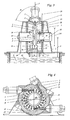
- FIG. 1 a Pelton turbine is mounted horizontally with its impeller axis (30) and is sprayed through the nozzles (2) and (2a) at their double cups (3) of the cup width "b" at a free jet diameter "D1" each with a free jet (6) ,
- the impeller (4) is covered by a housing (1) which is open towards the bottom to an underwater channel (8).
- the impeller center (9) is located at an installation height "F” above the water level (10) of the underwater channel (8).
- the free jet of a nozzle strikes the edges of a plane of symmetry (5) on the cutting of the passing double cup (3) and is deflected counter to the direction of rotation, whereby he fan-shaped and intermittently when leaving the cup as spray (7) to the housing (1 ) and hits the baffles (32).
- the spray water (7) of the nozzle (2) is best discharged into the underwater channel (8).
- the spray of the nozzle (2a) partially meets a baffle (32) roof-shaped over the next nozzle (2) is mounted in the direction of rotation to protect the free jet (6) from the stray splashing water shares (7a). It should be noted that the main direction of the spray water (7) also shifts according to a fall height change.
- the residual energy of the spray water is still so great that it is distributed in the entire housing (1, 1a, 1b) with foaming.
- the installation height "F” must correspond to twice the free-jet diameter "D1” so that the impeller (4) is not additionally braked by back-splashed spray water (7) and foam.
- the two supply lines (36), which arise as a branch from a common pressure line, could be supplemented by a further supply line (36) so as to form an arrangement according to FIG. 2 get.
- FIGS. 3 and 4 is an embodiment of a Pelton turbine with three out of five possible nozzles (2) and with a horizontally disposed impeller shaft (30) which is mounted in bearings (38) shown.
- Within the housing (1) there is an outer housing ring (11), which completely surrounds the impeller (4).
- An inner housing ring (12) sets on both sides of the impeller in each case in the region of the roots (17) of the cup and forms a radially conical with the outer housing ring (11) opening annulus (16).
- In the plane of symmetry (5) of the impeller emerging from the nozzle free jet (6) is divided at the cutting of the double cup and delivered after its deflection and impulse delivery to the cup in an annulus (16) at different exit angles.
- the arrangement shown with three nozzles (2) has the advantage that the nozzles are accessible from the outside.
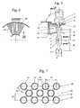
- the outer housing ring (11) forms an inwardly projecting roof-shaped projection (13) whose tip (15) in the plane of symmetry (5) and at a small distance "S1" from 5 to 20% of a cup length "1" the cups (3) is arranged to drain with the impeller circulating and auszentrifugieres splashing as early as possible in the annular space (16).
- In the plane of symmetry (5) are in each case openings (14) for the free jet (6) in the outer housing ring (11). Due to the small distance of the tip (15) to the cups 3, the free jet (6) remains unmolested on its way to the cups of water spray.
- the nozzles (2) are sealed to the outer housing ring (11), so that as little air is drawn in with the free jet.
- the free jet is in the opening (14) relatively narrow, but enclosed without contact, so that in the inwardly projecting roof shape caused by the interruption as small as possible attack surfaces for circulating spray water particles.
- the roof shape of the outer housing ring (11) forms with the plane of symmetry (5) an angle ⁇ of 75 °.
- each of the inner housing ring (12) with the plane of symmetry (5) forms an angle ⁇ of 75 °.
- the opening annular space (16) by a cylindrical connector in the outer housing ring (11) and by a cylindrical Housing for a bearing (38) continued.
- a brake grid (18) is installed, which is composed over the circumference of several segments.
- the grating part (18) of a segment consists of three layers of staggered tubes.
- the spray water After exiting the brake grid, the spray water is trapped by the housing (1) and falls under gravity through a perforated plate (39) in the underwater channel (8). There are therefore no more splash water blaster, which shoot like projectiles in the underwater channel and draw air to foam.
- the cylindrical housing for the bearing (38) is continued on the other wheel side and with an opening (40) for ventilation.
- the bearing (38) is covered by a non-contact labyrinth seal (37) to the impeller against splashing water, especially for protection during transient operating conditions.
- the segments of the brake grid (18) form a circular ring, with a passage surface (28), wherein a first position of the tubes in a plane (19) parallel to the symmetry plane (5) of the impeller.
- the plane (19) is slightly more than one cup width "b" away from the symmetry plane.
- FIGS. 16 and 17 is a supplement to FIG. 5 represented in which additional baffles 33 are mounted according to the number of free jets 6 in the annular space 16 in order to channel spray water, which emerges in the direction of rotation of the cup 3. This prevents the brake grille 18 generate a backwater due to unfavorable Anspritzwinkel.
- the baffles 33 have radially extending cutting edges 34 at a distance S3 to the cups from one tenth to one twentieth of the cup width b. They are at an angle ⁇ of 25 to 35 ° from the axial direction to the cups 3 out. Based on a perpendicular to the free jet 6 arranged radial 31, the cutting edges 343 are offset in the direction of rotation of the impeller by an angle ⁇ of 25-40 °.
- the baffles reach close to the brake grille or are bent down through the brake grille. Structurally, it is a cost-saving advantage to set the dividing walls between individual sectors of the brake grid in the circumferential direction so that they are designed as a bent continuation of the baffle.
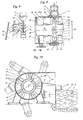
- FIGS. 8, 9 and 10 is a Pelton turbine in horizontal shaft arrangement with five nozzles (2) provided on the periphery.
- a conically opening annular space (16) continues cylindrically with a connecting piece (16b) in the outer housing ring (11) and continues in the inner housing ring (12) with a curvature towards the outer housing ring.
- baffles (32) are mounted, which are each assigned as a triad in the direction of rotation behind a nozzle (2).
- the baffles are in the direction of rotation in each case before the tangent point (29) of the associated nozzle to the free jet diameter "D1".
- the leading edge of the first guide plate (32) in the direction of rotation has a shortest distance "S2" to the cups, while the subsequent baffles (32) are further offset with their entry edges to the outside and the exit edges at a same distance to the impeller in a collecting channel ( 35).
- the exit angle ⁇ from the baffles to a perpendicular to the impeller axis is 45 °.
- the outer wall of the collecting channel (35) increases frontally in the circumferential direction of the cup in the form of a helix (42), which over a highest point "P", which is higher than the wheel center (9), an overflow into the underwater channel (8). Has. This residual energy obtained by the guided deflection is needed to overcome the highest point "P".
- the baffles (32) have a slight curvature opposite to the curvature of the cup halves.
- the distance "S2" of the leading edge of the leading baffle to the cups corresponds to 20 to 30% of the cup width "b". Since the kinetic energy of the spray water is exploited by a tight flow guidance, results in a compact design in which the nozzles are accessible from the outside, and results in a free slope "F", which accounts for only a fraction of the free jet diameter "D1".
- the annulus (16) is also in one Connection piece (16 b) to each nozzle with three baffles (32) provided as in FIG. 9 are staggered with respect to their entry edges to the cups.
- the exit direction has an additional radial component towards the outside.
- the emerging from the three baffles flow is guided in each case to a separate tangentially outgoing collecting channel (35a, 35b), wherein the lower collecting channel has an additional deflecting bend (43).
- the upper and lower collecting ducts (35a, 35b) lie above one another and lead tangentially upwards at an angle and via an overflow with the highest point P1, P2 into a spirally widening inlet (44) of the underwater duct 8. If this spiral inlet (44) is made sufficiently wide and deep, the distribution lines (36) to the nozzles (2) can cross the spiral without hindering the flow of water.
- FIG. 11 is at the transition from the spiral in the underwater channel (8) above the water level (10) a dashed line (18) indicated by dashed lines, which is to break the flow at the outlet of the foremost collecting ducts (35a, 35b).
- the free slope "F” is negative, since the wheel center (9) below the water level (10) of the underwater channel (8).
- Correspondingly large is the gain in height of fall, which corresponds to the sum of the negative distance "-F" and the usual free slope of two times the free jet diameter "D1".
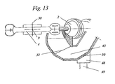
- the impeller (4) is located after a shutdown in a water-filled trough, which must be pumped empty at the next start, for example, with a jet pump. It may be helpful to continue running the pump throughout the startup process and to provide dedicated drain lines that collect backflowing flow portions in the suction area of the pump. This means that there must be an empty collecting container (48) below the Pelton turbine, into which the water flows can, wherein the container may also be the general swamp of the power plant.
- FIG. 13 is a section of the Umlenkbogens shown, which is interrupted by obliquely opening transverse slots (50), wherein the slots lead refluxing water via discharge lines (49) to the collection container. At the same time, the slots have the advantage that in normal operation during the deflection air is drawn through them, which reduces the friction for the longer path of the water on the underside of the impeller.
- FIGS. 14 and 15 is a six-nozzle system with vertical impeller axis (30) shown in vertical section and in horizontal section, wherein on the left side of the vertical section of the path of the spray water (7) is indicated.
- An annular or nozzle number "n" corresponding n-angular housing (1) is based on a concrete enclosure of the underwater channel (8).
- the nozzles (2) protrude far in the conventional design into the housing.
- An inner housing ring (12) sets in the upper part of the cup feet and is continued after a first bend of 45 ° in a conical ring part, which merges into a horizontal ring part, at which with a further bend of 20 ° down a conical ring part to connects to the outer wall of the housing (1).
- a three-layer brake grid (18) and below a perforated plate (39) are mounted at a distance of about two-thirds of the free jet diameter "D1" to the wheel center extend over the entire housing cross section.
- the brake grille brakes the pointed water and absorbs its kinetic energy, which otherwise leads to the air entering the underwater. With the slowing down of the flow and by the backwater on the slightly further distance perforated plate also air is still separated from the spray. Part of this air passes laterally in equalizing lines (47), which connect the uppermost space of the housing to the shaft with the underwater channel.
- the free slope "F" is about 1.2 times the free jet diameter "D1".
- FIG. 6 can consist of a circular ring with grid segments, also a working platform is provided, the full access to the impeller (4) granted when the longitudinally divided protective tube (46) is removed.
- the impeller (4) can be detached from the shaft, deposited on the column (45) and extended laterally through an opening in the housing, and mounted in reverse order.
- the nozzles (2) are accessible via this platform for maintenance purposes.
- the beams or tubes in the brake grid (18) may also extend in a direction other than radially to the rotor axis (30).
- the tubes (25) extend tangent in segments. The relative position of the tubes to each other corresponds to the in FIG. 7 ,
Abstract
Description
Die Erfindung betrifft eine Peltonturbine mit einem Wasserabfuhrsystem für Leistungen von mehr als 100 kW, wobei innerhalb eines Gehäuses ein Laufrad mit Doppelbechern einer Breite "b" und einer Becherlänge "1" bestückt ist, in welche Düsen, die in einer Symmetrieebene der umlaufenden Becher angeordnet sind, tangential auf einem Freistrahldurchmesser "D1" jeweils an einem Tangentenpunkt (29) einen Freistrahl einspritzen und wobei aus den Bechern austretendes Spritzwasser eingeschlossen durch Gehäusewände in einen Unterwasserkanal fällt.The invention relates to a Pelton turbine with a water removal system for outputs of more than 100 kW, within a housing, an impeller with double cups of a width "b" and a cup length "1" is fitted, in which nozzles arranged in a plane of symmetry of the rotating cup are, tangentially on a free jet diameter "D1" each at a tangent point (29) inject a free jet and wherein emerging from the cups splashing falls through housing walls in an underwater channel.
Bei einer Peltonturbine wird das gesamte Nutzgefälle in der Düse in Geschwindigkeitsenergie umgesetzt. Die Schaufeln der Doppelbecher sind so geformt, dass der Freistrahl von einer Mittelschneide in gleiche Teile geschnitten und im Becher um nahezu 180° umgelenkt wird. Durch die Umlenkung wird fast die gesamte kinetische Energie des Wasserstrahles in Impulskraft am Radumfang umgesetzt. Die verbleibende Restenergie von etwa 2 bis 4 % ist noch als Geschwindigkeitsenergie vorhanden, um die Becher gut und schnell zu entleeren und geht größtenteils in etwa Achsrichtung aufgefächert beiderseits des Laufrades in das Turbinengehäuse bzw. auf die freie Oberfläche des Unterwasserkanals.In a Pelton turbine, the entire useful gradient in the nozzle is converted into speed energy. The blades of the double cups are shaped so that the free jet is cut by a central cutting edge into equal parts and deflected in the cup by almost 180 °. As a result of the deflection, almost the entire kinetic energy of the water jet is converted into momentum at the circumference of the wheel. The remaining residual energy of about 2 to 4% is still available as a velocity energy to empty the cups well and quickly and mostly fanned in about axial direction on both sides of the impeller in the turbine housing or on the free surface of the underwater channel.
Die eine Peltonturbine der eingangs angegebenen Art beschreibende Patentschrift
Die Patentschrift
In
In
Die Patentschrift
Die Patentschrift
Bei Turbinen mit vertikaler Laufradachse (1-6 düsig) wird das nach oben austretende Wasser an der Decke zur Gehäuseaußenwand umgelenkt und nach oben abgeführt. Das aus der unteren Becherhälfte austretendeOn turbines with a vertical impeller axis (1-6 nozzles), the water that escapes upwards is deflected on the ceiling to the outer wall of the housing and removed upwards. The emerging from the lower cup half
Wasser trifft meist schräg die Außenwand bzw. direkt auf den freien Wasserspiegel auf. Das noch mit relativ hoher Geschwindigkeit aus den zwei Becherhälften austretende Wasser reisst noch sehr viel Luft, zwischen 30 und 70 % der Wassermenge, mit und verwirbelt im starken Masse die Oberfläche des Unterwasserkanals. Um das Laufrad sicher vor den Auswirkungen der Schaumbildung zu schützen liegt es mit seinem Laufradmittelpunkt um den Freihang "F" d.h. etwa dem Zweifachen vom Freistrahldurchmesser "D1" höher als der Pegel des Unterwasserkanals, was einen Fallhöhen- bzw. Energieverlust bedeutet (siehe
Bei Turbinen mit horizontaler Laufradachse (1-3 düsig) wird das Wasser seitlich , in Achsrichtung, an das Gehäuse gespritzt und über geeignete Umlenkungen nach unten abgeführt. Die Anzahl der Düsen ist wegen der schlechten Wasserabführung oben liegender Düsen aus dem Gehäuse auf (1) bis 2, maximal 3 begrenzt. Der Freihang "F" ist ähnlich wie bei der vertikalen Turbine dimensioniert. Bei höherer Düsenzahl ist die Entwässerung problematisch und nur noch mit Einbussen am Wirkungsgrad bzw. Leistung, vor allem im Vollastbereich möglich, weil das Austrittswasser nach oben abgelenkt wird, ohne dass es aus dem Bereich des Laufrades entfernt ist (siehe
Die grosse Schaumbildung hat nicht nur zur Folge, dass der Freihang entsprechend gross gewählt werden muss, sondern auch dass dieser Schaum über lange Beruhigungsstrecken abgebaut werden muss, wenn das Wasser weiter verwendet wird.
Letzteres ist bei Pelton- Gegendruckturbinen der Fall, wenn sie im Stand by Betrieb im "hydraulischen Kurzschluss" mit einer Pumpe am gleichen Wellenstrang laufen, um bei Bedarf in wenigen Sekunden eine verlangte Last an einen Generator abzugeben. Solche Anforderungen treten beispielsweise bei Pumpspeicheranlagen mit Peltonturbinen im Gegendruckbetrieb auf. Hohe Lastregelschwankungen treten dort mit starken Wasserstrom- und Druckschwankungen auf, welche das Laufrad mit Schwall-und Schaumbildung beeinträchtigen können. Um Pelton- Gegendruckturbinen bei stark schwankendem Unterwasserpegel sicher betreiben zu können, müssen diese durch Druckluft auf einer Kote frei geblasen werden, die einen sicheren schaumfreien Betrieb ermöglicht. In der Turbinenkammer wirkt dann ein Druck, der der jeweiligen Unterwasserkote des zugehörigen Unterwasserbeckens entspricht. Die über das Laufrad in das Unterwasser eingetragene Luft wird unterschieden in einen gelösten Anteil, der sich durch Entspannung aus dem Druckunterschied vor und nach der Düse ergibt, und in einen ungelösten Anteil, der vom Spritzwasser mitgerissen wird. Die Länge der Ausperlstrecke im Unterwasserkanal ist abhängig von der Eintragtiefe unter dem Laufrad sowie der gleichmäßigen Strömungsverteilung nach dem Laufrad. Damit sich das Niveau im Unterwasserkanal nicht verändert, muss der fehlende Luftanteil über Kompressoren ersetzt werden.The large foaming not only has the consequence that the free slope must be chosen correspondingly large, but also that this foam must be degraded over long calming distances, if the water is still used.
The latter is the case with Pelton backpressure turbines when they run in stand-by mode in the "hydraulic short circuit" with a pump on the same shaft strand to deliver a demanded load to a generator in a few seconds if necessary. Such requirements occur for example in pumped storage plants with Pelton turbines in counter-pressure operation. High load control fluctuations occur there with strong water flow and pressure fluctuations, which can affect the impeller with surge and foaming. In order to be able to safely operate Pelton backpressure turbines with heavily fluctuating subsea levels, they must be blown free by compressed air on a kote, which enables safe foam-free operation. In the turbine chamber then acts a pressure that corresponds to the respective Unterwasserkote the associated underwater basin. The air introduced into the underwater via the impeller is differentiated into a dissolved fraction, which results from the pressure difference before and after the nozzle due to relaxation, and into an undissolved fraction, which is entrained by the sprayed water. The length of the breather section in the underwater channel depends on the depth of entry under the impeller and the uniform flow distribution downstream of the impeller. So that the level in the underwater canal does not change, the missing air portion must be replaced by compressors.
Jede Verlängerung eines Unterwasserkanals, der fast immer in einer Kaverne liegt, verteuert die Baukosten, wenn sie nur dem Ausgasen von Luft dient. Ein weiterer Punkt ist der, dass die Garantiegrenze für die entsprechend den IEC 60041- Richtlinien garantierten Leistungswerte bei dem Turbinenhersteller mit der Höhe vom Laufradmittelpunkt aufhört, während ein bestimmter Freihang, der ausserhalb dieser Garantiegrenze definiert ist, dem Betreiber vorgegeben wird, der bauseitig dafür zu sorgen hat, dass die Wasserabfuhr funktioniert. Aus diesem Grund hat sich einAny extension of an underwater canal, which is almost always in a cavern, increases the cost of construction, if it only serves the outgassing of air. Another point is that the guarantee limit for the guaranteed performance according to the IEC 60041 directives ceases at the turbine manufacturer's height from the center of the impeller, while a specific free-fall, defined outside this guarantee limit, is given to the operator, on-site has ensured that the drainage works. Because of this, a
Standard für den Freihang "F" eingebürgert, der bei dem Zweifachen des Freistrahldurchmessers "D1" liegt und der beim Betrieb der Anlagen wegen Schaumbildung auch voll ausgenutzt wird.Standard for the free slope "F" naturalized, which lies at twice the free jet diameter "D1" and which is also fully utilized during the operation of the plants because of foam formation.
Aufgabe der Erfindung ist es, die Entwässerung der Turbine auch bei geringeren Düsenzahlen, insbesondere bei zwei bis vier Düsen so zu verbessern, dass der Freihang um einen wesentlichen Betrag verkleinert werden kann, dass also Fallhöhe durch einen tiefer liegenden Einbau des Laufradmittelpunktes gewonnen wird.The object of the invention is to improve the drainage of the turbine even at lower nozzle numbers, especially at two to four nozzles so that the free slope can be reduced by a substantial amount, so that fall height is obtained by a deeper installation of the impeller center.
Gemäß der Erfindung wird dies im Wesentlichen dadurch erreicht, dass innerhalb des Gehäuses 1 einerseits an den Bechern 3 ansetzend über den vollständigen Umfang des Laufrades 4 als Führungsmittel, das Spritzwasser führt und umlenkt, ein innerer, bis an die Wurzeln 17 der Becher 3 herangeführter Gehäusering 12 und andererseits als weiteres Führungsmittel, das Spritzwasser führt und umlenkt, ein satteldachförmiger äußerer Gehäusering 13 vorgesehen ist, wobei die Spitze des satteldachförmigen Gehäuserings 13 in der Symmetrieebene 5 gelegen ist und innerer und äußerer Gehäusering 12, 13 Ringräume 16 zur Führung des aus den Bechern austretenden Spritzwassers bilden.According to the invention this is achieved essentially by the fact that within the
Der Erfindung liegt die Erkenntnis zu Grunde, dass der "Luftbedarf" der Turbine stark von der Weglänge und der Ausbreitungsmöglichkeit der Spritzwasserpartikel bis zum Austreffen auf die Oberfläche des Unterwasserkanals abhängig ist. Das heißt, bei eng geführtem beziehungsweise eng gebündeltem Spritzwasser wird die Angriffsfläche zur Luftanreicherung entsprechend reduziert. Dies darf aber nicht soweit führen, dass bei Normalbetrieb Spritzwasser zum Laufrad zurückgestaut wird.The invention is based on the finding that the "air requirement" of the turbine is heavily dependent on the path length and the possibility of propagation of the spray water particles until they reach the surface of the underwater channel. That is, in narrowly guided or tightly bundled spray the attack surface for air enrichment is reduced accordingly. However, this must not lead so far that during normal operation splash water is dammed back to the impeller.
Des weiteren liegt die Erkenntnis zu Grunde, dass das Laufrad und der Laufradbereich möglichst frei von vagabundierenden Spritzern und Wassernebel sein sollte, um die Ventilationsverluste niedrig zu halten.Furthermore, the finding is based on the fact that the impeller and the impeller area should be as free as possible of stray splashes and water mist in order to keep the ventilation losses low.
Die Erfindung hat den Vorteil, dass die Installationshöhe "F" für das Laufrad auf weniger als das 1,5- fache des Freistrahldurchmessers festgelegt werden kann. Bei einer ursprünglichen Fallhöhe von 200m und einem Laufrad mit Freistrahldurchmesser von einem Meter entspricht dies einer Verbesserung um etwa 0,5 m der Fallhöhe d.h. 0,25%. Dadurch dass mit dem Verlassen der Becher eine gezielte Abfuhr des Spritzwassers erfolgt, die von anderen vagabundierenden Spritzwasserteilen abgeschirmt ist, können letztere sich weder an einer Vergrösserung der Schaumbildung noch an einem Bremsen am Laufrad beteiligen, wobei die Schaumbildung auch durch Bremsgitter, die parallel zum Laufrad angeordnet sind wesentlich reduziert wird. Wenn man bedenkt, dass die Turbinenhersteller im Augenblick für eine Wirkungsgradverbesserung von 0,1% eine Entwicklungszeit von einem Jahr annehmen, dann sind die hier aufgezeigten Vorteile offensichtlich.The invention has the advantage that the installation height "F" for the impeller can be set to less than 1.5 times the free jet diameter. At an initial drop height of 200m and a free-jet diameter impeller of one meter, this corresponds to an improvement of about 0.5 m in drop height, i. 0.25%. The fact that with the leaving of the cups targeted removal of the spray water is shielded from other stray splash water parts, the latter can participate neither in an increase in the foam formation on a brake on the impeller, the foaming also by brakes, parallel to the impeller arranged are substantially reduced. Considering that turbine manufacturers are currently developing for one year at 0.1% efficiency improvement, the benefits shown here are obvious.
Durch die Erfindung ist es möglich vertikale und horizontale Peltonturbinen mit hoher Energiedichte entsprechend der Anzahl der Düsen, das heisst mit einem Laufrad gleicher Grösse ohne Leistungs-Einbussen wegen Spritzwassers bis zu 6-düsig auszuführen.By the invention it is possible vertical and horizontal Pelton turbines with high energy density corresponding to the number of nozzles, that is run with an impeller of the same size without power losses due to splashing up to 6 nozzle.
Die Erfindung verbessert ebenfalls ein gutes Abführen des Spritzwassers bei wenig Luftbedarf und verhindert gleichzeitig Störungen der mitumlaufenden Ventilationsluft, da keine hineinragenden Düsen sich störend auswirken können.The invention also improves a good discharge of the spray water with little air requirement and at the same time prevents disturbances of the circulating ventilation air, since no protruding nozzles can interfere.
Die abhängigen Ansprüche 2 bis 9 stellen vorteilhafte Weiterbildungen des Gegenstandes der Erfindung dar.The dependent claims 2 to 9 represent advantageous developments of the subject invention.
Ein innerhalb des Gehäuses vorgesehener äußerer Gehäusering, der in der Symmetrie-Ebene in einem Abstand "S1" von 5% bis 20% einer Becherlänge "1" zu den Bechern angeordnet ist, erbringt wesentliche Vorteile, da er das direkt aus den Bechern austretende Spritzwasser vor reflektiertem vagabundierenden Spritzwasser schützt. Ein weiterer Vorteil liegt darin, dass bei einer dickeren Gestaltung dieses äusseren Gehäuseringes im Bereich der Symmetrie-Ebene die Freistrahlen in tangential zu dem Freistrahldurchmesser "D1" geführten Durchbrüchen ebenfalls vor vagabundierendem Spritzwasser geschützt sind. Wenn diese Verdickung in der Symmetrie-Ebene als Spitze eines dachförmig zum Laufrad vorstehenden Vorsprungs ausgeführt ist, kann gleichzeitig eine der Austrittsrichtung entsprechende seitliche Begrenzung für das Spritzwasser geschaffen werden. Solange die Düsen über den dachförmigen Vorsprung nach innen hineinragen, können sie selbst mit ihrem Düsenkörper nicht an der Erzeugung von vagabundierendem Spritzwasser beteiligt sein, während der äussere Gehäusering dafür sorgt, dass sich das aussen an ihm vorbei bewegende Spritzwasser nicht mit dem Spritzwasser auf seiner Innenseite vermischen kann. Je geringer die Durchbrüche im äusseren Gehäusering von dem Durchmesser eines Freistrahls abweichen, desto kleiner ist auf der Innenseite die von der Dachform abweichende Angriffsfläche für das Dispergieren von Spritzwasser. Wenn die Düsenkörper vollständig gegen den äusseren Gehäusering abgedichtet sind, kann keine Luft eingesogen werden, was beim Betrieb mit Luft-Überdruck im Gehäuse eine Rolle spielen kann. Solche Systeme existieren bei den oben erwähnten Anlagen zum Abfangen von Spitzenlasten, bei denen Turbine und Pumpe im hydraulischen Kurzschluss gefahren werden. Dort bilden Turbinengehäuse und Unterwasserkanal eine geschlossene Atmosphäre mit Überdruck, in welche von Kompressoren Luft eingeblasen wird, um die vom Spritzwasser mitgenommenen Luftanteile zu ersetzen. Wenn hier das Schäumen, d.h. der Lufteintrag vermindert wird, kann die Kompressorleistung kleiner dimensioniert werden.An outer casing ring provided inside the casing, which in the symmetry plane is at a distance "S1" of 5% to 20% of a cup length "1" is arranged to the cups, provides significant benefits, as it protects the exiting directly from the cups splashing water from reflected stray spraying. Another advantage is that in a thicker design of this outer housing ring in the symmetry plane, the free jets in breakthroughs guided tangentially to the free jet diameter "D1" are also protected from stray spray water. If this thickening in the plane of symmetry is carried out as a tip of a roof-shaped projecting projection to the impeller, at the same time a lateral boundary for the spray water corresponding to the discharge direction can be created. As long as the nozzles protrude inwards beyond the roof-shaped projection, they themselves can not participate in the generation of stray spraying water with their nozzle body, while the outer housing ring ensures that the spray water moving past it on the outside does not splash with the spray water on its inside can mix. The smaller the apertures in the outer housing ring deviate from the diameter of a free jet, the smaller is the attack surface on the inside deviating from the roof shape for the dispersion of sprayed water. If the nozzle bodies are completely sealed against the outer housing ring, no air can be sucked in, which can play a role in the operation with air pressure in the housing. Such systems exist in the above-mentioned systems for intercepting peak loads, in which the turbine and pump are driven in hydraulic short circuit. There turbine casing and underwater channel form a closed atmosphere with overpressure, in which air is injected by compressors to replace the entrained air splashing air. If here the foaming, ie the air intake is reduced, the compressor power can be made smaller.
Ein beiderseits vom Laufrad umlaufender innerer Gehäusering, der bis an die Wurzeln der Becher herangeführt ist, verbessert zusätzlich die Führung des aus den Bechern austretenden Spritzwassers. Es entsteht ein ringförmiger sich senkrecht von der Symmetrie-Ebene weg konisch öffnender Kanal, wobei die halben Öffnungswinkel α und β zwischen 55° und 80° gewählt sind, um die Ablaufrichtung des Spritzwassers aus den Bechern zu berücksichtigen. Ein Optimum für die Winkel α und β liegt zwischen 65° und 75°. Wenn das Spitzwasser in einem schleifend einfangenden Ringraum kanalisiert ist, kann dieser durch ein zylindrisches Anschlussstück fortgesetzt werden und sich später sogar verjüngen. Bautechnisch ist es sinnvoll, das zylindrische Anschlussstück auf einen Abstand von dem 1,4- bis dem 2-fachen der Becherbreite "b" von der Symmetrie-Ebene weg fortzusetzen.An encircling on both sides of the impeller inner casing ring, which is brought up to the roots of the cup, additionally improves the leadership of emerging from the cups spray water. The result is an annular channel which opens conically away perpendicularly from the plane of symmetry, the half opening angles α and β being selected between 55 ° and 80 °, in order to take into account the direction of flow of the spray water from the cups. An optimum for the angles α and β is between 65 ° and 75 °. When the pointed water is channeled in a drag-trapping annulus, it can be continued through a cylindrical fitting and later even tapered. Structurally, it makes sense to continue the cylindrical connector to a distance of 1.4 to 2 times the cup width "b" away from the plane of symmetry away.
Im zylindrischen Anschlussstück selbst oder daran anschliessend kann ein Bremsgitter vorgesehen sein, das auf einer Durchtrittsfläche mit einem mittleren Durchmesser entsprechend dem Freistrahldurchmesser "D1" und einer Ringbreite entsprechend mindestens einer Becherlänge "1" parallel zum Laufrad angeordnet ist, um Spritzwasser möglichst schaumfrei abzubremsen.In the cylindrical connection piece itself or adjoining thereto, a brake grid can be provided, which is arranged on a passage surface with an average diameter corresponding to the free jet diameter "D1" and a ring width corresponding to at least one cup length "1" parallel to the impeller in order to decelerate spray water as foam-free as possible.
Ein Gitter entwickelt generell eine Schaum unterdrückende Wirkung und kann auch in bestehende Anlagen eingebaut werden. Zum Beispiel kann bei vertikaler Laufradachse unterhalb des Laufrades quer durch das Gehäuse über dessen ganzen Querschnitt ein Gitter angeordnet sein, um die Schaumbildung zu verringern.A grid generally develops a foam-suppressing effect and can also be installed in existing plants. For example, with a vertical impeller axis below the impeller, a grating may be disposed across the housing over its entire cross section to reduce foaming.
Das Bremsgitter weist mindestens zwei Lagen von in einer Ebene parallel zu der Symmetrie-Ebene in einem Abstand zum Laufrad angeordneten Balken auf, die pro Lage in gleichem Abstand zueinander angeordnet sind. Dabei beträgt in einer Lage der Durchmesser der Balken 60% bis 70% des Mittenabstandes zweier benachbarter Balken. Die nächstfolgende Lage von gleich ausgerichteten Balken kann um einen halben Mittenabstand zu der davor liegenden Lage versetzt sein. Die Balken selbst haben einen runden Querschnitt und sind vorzugsweise als Rohre ausgeführt. Diese können beispielsweise zur Dämpfung mit Sand oder Split gefüllt werden, wenn sie durch die intermittierende Beaufschlagung mit Spritzwasser zu Schwingungen angeregt werden sollten. Um beispielsweise eine gute mechanische Stabilität eines Bremsgitters zu erreichen kann man drei Lagen von Rohren in Sandwichbauweise mit kurzen um 80 bis 90° versetzten Abstandshaltern verbinden.The brake grid has at least two layers of bars arranged in a plane parallel to the plane of symmetry at a distance from the wheel, which are arranged at the same distance from one another per layer. In this case, in one position, the diameter of the bars is 60% to 70% of the center distance of two adjacent bars. The next following layer of equally aligned beams can be offset by half the center distance to the preceding layer. The bars themselves have a round cross section and are preferably designed as tubes. These can be filled, for example, for damping with sand or split, if they should be excited by the intermittent impingement with spray water to vibrate. For example, to achieve a good mechanical stability of a brake grid can connect three layers of pipes in sandwich construction with short offset by 80 to 90 ° spacers.
Es hat sich als vorteilhaft erwiesen eine Anordnung zu wählen, bei der Sektoren von 3-lagigen Gittern wie Tortenstücke zu einem Kreisring zusammengesetzt sind. Die Lage der Balken oder Rohre ist dabei annähernd radial angeordnet. Die runde Form der Balken hat zunächst den Vorteil, dass ihre Wirkung wenig richtungsabhängig ist, wenn die Spritzwasserplatscher mit grosser Geschwindigkeit auftreffen. Eine weitere Wirkung besteht darin dass diese Spritzwasserplatscher in sich verformt werden, wenn sie auf der runden Oberfläche auftreffen. Bei einem versetzten Auftreffen auf der gekrümmten Oberfläche setzt eine Längung und Abbremsung der Spritzwasserplatscher ein, die an der darauf folgenden Lage fortgesetzt wird.It has proved to be advantageous to choose an arrangement in which sectors of 3-ply meshes such as pie pieces are assembled into a circular ring. The position of the beams or tubes is arranged approximately radially. The round shape of the beams initially has the advantage that their effect is little dependent on the direction when the splash splatter strike at great speed. Another effect is that these spray splashers are deformed when they hit the round surface. In a staggered impact on the curved surface begins an elongation and deceleration of the splash splatter, which is continued at the subsequent location.
Um die Wirkung unterschiedlicher Austrittswinkel des Wassers aus den Bechern zu den Bremsgittern herabzumindern und um eine kurze Verweilzeit im Ringraum zu den Bremsgittern sicher zu stellen, haben Modellversuche gezeigt, dass Leitbleche mit einem Anstellwinkel ϕ von 25 bis 35° in einem Abstand S3 von 1/10 bis 1 / 20 der Becherbreite b an die Becher herangeführt eine weitere Verbesserung der Wasserabfuhr durch das Bremsgitter ergeben. In Bezug auf die dem Becher zugewandte Schneide des Leitblechs sollte diese im Ringraum von einer senkrecht zum Freistrahl angeordneten Radialen in Umlaufrichtung um einen Winkel λ von 25 bis 40° versetzt sein. Unterschiedliche Austrittswinkel entstehen beispielsweise bei stark variierender Fallhöhe. Anders ausgedrückt: mit derartigen Leitblechen kann mit der gleichen Anordnung eine ähnlich gute Wirkung der Bremsgitter für verschiedene Fallhöhen erreicht werden.In order to reduce the effect of different outlet angles of the water from the cups to the brake grilles and to ensure a short residence time in the annular space to the brake grilles, model tests have shown that baffles with an angle of incidence φ of 25 to 35 ° at a distance S3 of 1 / 10 to 1/20 of the cup width b brought to the cup a further improvement of water removal by give the brake grid. With respect to the cup facing the baffle this should be offset in the annular space of a perpendicular to the free jet radial arranged in the direction of rotation by an angle λ of 25 to 40 °. Different exit angles arise, for example, with greatly varying drop height. In other words: with such baffles, a similarly good effect of the brake grille for different fall heights can be achieved with the same arrangement.
Bei einer horizontal angebrachten Laufradachse lässt sich beiderseitig vom Laufrad ein Bremsgitter anbringen, an welches ein Fallschacht zum Unterwasserkanal anschliesst, was in Kombination mit einem äusseren Gehäusering besonders wirkungsvoll ist, wenn die Bremsgitter an den Ring anschliessen. Bei einem fliegend gelagerten Laufrad kann die Welle in dem Fallschacht durch Schutzbleche ummantelt werden um dort nicht auch noch dem Spritzwasser ausgesetzt zu sein.With a horizontally mounted impeller axis can be attached to both sides of the impeller, a brake grid, which is followed by a chute to the underwater channel, which is particularly effective in combination with an outer housing ring when the brake grille connect to the ring. In a cantilevered impeller, the shaft can be sheathed in the chute through fenders so as not to be exposed to the spray water.
Ferner kann bei einer horizontal angeordneten Laufradachse, speziell im Hinblick auf eine Anlage mit mehr als drei gleichmässig am Umfang verteilten Düsen, ein beidseitig angebrachter Ringraum mit äusserem und inneren Gehäusering so durch Leitbleche zwischen innerem und äusserem Gehäusering ergänzt werden, dass dort keine rotierende Strömung in umlaufender Richtung entsteht, sondern das Spritzwasser gezielt in einen Sammelkanal umgelenkt wird. Dadurch dass die profilierten Leitbleche in umlaufender Richtung vor dem Strahleintritt einer nachfolgenden Düse angebracht sind, wird eine Kreuzung mit Spritzwasser der nachfolgenden Kammer vermieden. Um unabhängig vom Betriebszustand Wasserspritzer in vor- und rücklaufender Richtung ableiten zu können sind je Düsenanordnung zwei bis drei in umlaufender Richtung hintereinander gestaffelte Leitbleche unterschiedlicher Länge angebracht, wobei der Abstand "S2" des ersten Leitbleches zu den Bechern zwischen 10% bis 30% der Becherbreite "b" beträgt und ein Austrittswinkel γ von 35 bis 45° zu einer Senkrechten zur Laufragachse besteht. Die Leitbleche enden beiderseits des Laufrades in Umlaufrichtung der Becher gekrümmt als gleich gerichtete Führungen in einem umlaufenden Sammelkanal, von denen mindestens der Sammelkanal auf der Wellenseite spiralförmig ausgeführt ist, um alles Spritzwasser dieser Seite dank seiner restlichen kinetischen Energie über einen Punkt "P" oberhalb der Laufradachse zu führen und so Fallhöhe einzusparen, da nach dem Punkt "P" ein geringes Gefälle zum Unterwasserkanal ausreichend ist. Wenn beide Seiten mit einem derartigen Sammelkanal versehen sind, liegt das Laufrad mehr als hälftig in einem Trog, der über einen höchsten, über dem Wasserspiegel liegenden Punkt mit dem Unterwasserkanal verbunden ist und der bei einem Start der Anlage beispielsweise mit einer Strahlpumpe leer geschöpft wird. Bei Anlagen im Dauerbetrieb, die vielleicht nur wenige Unterbrüche pro Jahr haben. ist dies eine vertretbare Betriebsart, bei der die Vorteile von einer mehr als dreidüsigen Anordnung für eine horizontale Wellenanordnung überwiegen.Furthermore, in a horizontally arranged impeller axis, especially with regard to a system with more than three evenly distributed nozzles, a double-sided annular space with outer and inner housing ring are complemented by baffles between the inner and outer housing ring that there is no rotating flow in circumferential direction, but the spray is directed specifically into a collecting channel. The fact that the profiled baffles are mounted in the circumferential direction before the jet inlet of a subsequent nozzle, a crossing with water spray of the subsequent chamber is avoided. In order to be able to dissipate water splashes in the forward and backward direction independently of the operating state, two to three staggered guide plates of different lengths are arranged per nozzle arrangement, the distance "S2" of the first guide plate to the cups being between 10% and 30% of the cup width "b" is and an exit angle γ of 35 to 45 ° to a perpendicular to the Laufragachse. The baffles end on both sides of the impeller curved in the direction of rotation of the cup as identically directed guides in a circumferential collection channel, of which at least the collection channel on the shaft side is spirally designed to spray all this page thanks to its residual kinetic energy through a point "P" above the To guide the wheel axis and thus to save height, since after the point "P" a slight downward gradient to the underwater channel is sufficient. If both sides are provided with such a collection channel, the impeller is more than half in a trough, which is connected via a highest, lying above the water level point with the underwater channel and which is scooped empty at a start of the system, for example with a jet pump. For facilities in continuous operation, which may have only a few interruptions per year. this is an acceptable mode of operation in which the benefits outweigh a more than three-nozzle arrangement for horizontal shaft assembly.
Bei einer weiteren Lösung für vertikal angeordneten Peltonturbinen wird das Spritzwasser, welches die eine Becherhälfte nach oben verlässt, über Leitbleche umgelenkt und jeweils tangential weg in einen oberen Sammelkanal abgeführt. Das Spritzwasser aus der unteren Becherhälfte, das nach unten abströmt, wird pro Düse über Leitbleche und tangential weg in einen nach oben abgewinkelten Sammelkanal nach oben gefördert. Die oberen und unteren Sammelkanäle münden über einen Überlauf in einen spiralförmigen Zulauf für den gemeinsamen Unterwasserkanal, wobei der Austritt des oberen Spritzwassers auf einer höheren Kote erfolgt. Dadurch, dass das obere Spritzwasser einen nur kurzen reibungsbehafteten Weg hat, kann es höher fördern. Das untere Spritzwasser wird ebenfalls auf möglichst kurzem Weg nach oben gefördert.In another solution for vertically arranged Pelton turbines, the spray water, which leaves the one cup half up, deflected by baffles and each tangentially away in an upper collecting channel. The spray water from the lower half of the cup, which flows downwards, is conveyed per nozzle over baffles and tangentially away in an upwardly angled collecting channel upwards. The upper and lower collection channels open via an overflow in a spiral inlet for the common underwater channel, wherein the outlet of the upper spray water takes place on a higher Kote. The fact that the upper spray has only a short frictional path, it can promote higher. The lower spray is also promoted on the shortest possible way up.
Der Fallhöhengewinn ist hierbei von der Restgeschwindigkeit und diese wiederum von der Nettofallhöhe und von der Becherauslastung abhängig. Die verbleibende Energie am Becheraustritt beträgt zwischen 2 und 4% der Gesamtenergie. Bei einem Ausnützungsfaktor von 0,3 für diese Restenergie kann das Spritzwasser um 0,6 bis 1,2% der Fallhöhe auf einen Punkt "P" über dem Laufradmittelpunkt gefördert werden und mit geringem Gefälle in den Unterwasserkanal fliessen. Da als Fallhöhengewinn ebenso der Freihang dazu gerechnet wird ist für dieses Beispiel mit einem Gewinn an Gesamtenergie von 0,8 bis 1,4% zu rechnen.The fall height gain depends on the residual velocity, which in turn depends on the net head and the cup utilization. The remaining energy at the cup outlet is between 2 and 4% of the total energy. With a utilization factor of 0.3 for this residual energy, the spray water can be conveyed by 0.6 to 1.2% of the drop height to a point "P" above the wheel center and flow with a slight gradient into the underwater channel. As the free fall is also counted as fall height gain, a gain in total energy of 0.8 to 1.4% is to be expected for this example.
Nachfolgend wird die Erfindung anhand von Ausführungsbeispielen beschrieben. Es zeigen
- Fig. 1:
- aus dem Stand der Technik schematisch eine Peltonturbine mit horizontaler Wellenanordnung und mit zwei Düsen,
- Fig. 2:
- aus dem Stand der Technik schematisch eine Peltonturbine mit horizontaler Wellenanordnung und mit drei Düsen,
- Fig. 3:
- schematisch eine erfindungsgemässe Anordnung für eine Peltonturbine mit horizontaler Welle und mit drei Düsen in einer Seitenansicht,
- Fig. 4:
- schematisch die
Anordnung von Figur 3 in einer Frontalansicht, - Fig. 5:
- schematisch einen vergrösserten Ausschnitt aus
Figur 3 mit einem Sektor von einem Bremsgitter, - Fig. 6:
- schematisch eine Ansicht auf den Sektor des Bremsgitters in
Figur 5 - Fig. 7:
- schematisch einen vergrösserten Schnitt durch ein Bremsgit- ter nach
Figur 6 , welches aus drei Lagen von Rohren in Sandwichbauweise besteht, - Fig. 8:
- schematisch einen Ausschnitt einer Peltonturbine mit hori- zontaler Wellenanordnung und mit einem mit Leitblechen be- stückten Ringraum für Spritzwasser,
- Fig. 9:
- schematisch einen Ausschnitt von Leitblechen in
Figur 8 - Fig. 10:
- schematisch einen
Schnitt von Figur 8 mit Blick auf die Leit- bleche, - Fig. 11:
- schematisch einen vertikalen Schnitt von einer Peltonturbine in vertikaler Anordnung mit fünf Düsen und mit einem nega- tiven Freihang F,
- Fig. 12:
- schematisch einen horizontalen Schnitt durch die
Turbine von Figur 11 , - Fig. 13:
- schematisch einen vergrösserten Ausschnitt eines Umlenkbo- gens mit
Schlitzen aus Figur 12 , - Fig. 14:
- schematisch einen vertikalen und
- Fig. 15:
- einen horizontalen Schnitt von einer Peltonturbine in vertika- ler Anordnung mit sechs Düsen und mit nur einem Bremsgit- ter,
- Fig. 16:
- schematisch eine Anordnung gemäß
Fig. 5 , bei der ein Leit- blech mit einer radial verlaufenden Schneide dargestellt ist, und - Fig. 17:
- schematisch eine Seitenansicht von
Fig. 16 .
- Fig. 1:
- from the prior art schematically a Pelton turbine with horizontal shaft arrangement and with two nozzles,
- Fig. 2:
- from the prior art schematically a Pelton turbine with horizontal shaft arrangement and with three nozzles,
- 3:
- 1 schematically shows an arrangement according to the invention for a Pelton turbine with horizontal shaft and with three nozzles in a side view,
- 4:
- schematically the arrangement of
FIG. 3 in a frontal view, - Fig. 5:
- schematically an enlarged section of
FIG. 3 with a sector of a brake grid, - Fig. 6:
- schematically a view of the sector of the brake grid in
FIG. 5 . - Fig. 7:
- schematically an enlarged section through a brake grille after
FIG. 6 , which consists of three layers of tubes in sandwich construction, - Fig. 8:
- 2 shows schematically a section of a Pelton turbine with a horizontal wave arrangement and with an annular space for spray water, equipped with baffles, FIG.
- Fig. 9:
- schematically a section of baffles in
FIG. 8 with its arrangement to the impeller, - Fig. 10:
- schematically a section of
FIG. 8 with a view of the baffles, - Fig. 11:
- 1 is a vertical section of a Pelton turbine in a vertical arrangement with five nozzles and with a negative free slope F,
- Fig. 12:
- schematically a horizontal section through the turbine of
FIG. 11 . - Fig. 13:
- schematically an enlarged section of a deflection with slots from
FIG. 12 . - Fig. 14:
- schematically a vertical and
- Fig. 15:
- a horizontal section of a Pelton turbine in a vertical arrangement with six nozzles and with only one brake grille,
- Fig. 16:
- schematically an arrangement according to
Fig. 5 , in which a guide plate is shown with a radially extending cutting edge, and - Fig. 17:
- schematically a side view of
Fig. 16 ,
In den nachfolgenden Beispielen sind funktional gleiche Teile mit gleichen Hinweiszeichen versehen.In the following examples, functionally identical parts are provided with the same reference symbols.
In
Der Freistrahl einer Düse trifft auf die Schneiden einer Symmetrie-Ebene (5) auf die Schneiden der vorbeilaufenden Doppelbecher (3) und wird entgegen der Umlaufrichtung umgelenkt, wobei er beim Verlassen der Becher als Spritzwasser (7) fächerförmig und intermittierend an das Gehäuse (1) und an die Ablenkbleche (32) auftrifft. Dabei wird das Spritzwasser (7) der Düse (2) am besten in den Unterwasserkanal (8) abgeleitet. Das Spritzwasser der Düse (2a) trifft teilweise aus ein Leitblech (32) das dachförmig über die nächste Düse (2) in Drehrichtung angebracht ist um den Freistrahl (6) vor den vagabundierenden Spritzwasseranteilen (7a) zu schützen. Zu bemerken dazu ist, dass sich die Hauptrichtung des Spritzwassers (7) entsprechend einer Fallhöhenänderung ebenfalls verschiebt.The free jet of a nozzle strikes the edges of a plane of symmetry (5) on the cutting of the passing double cup (3) and is deflected counter to the direction of rotation, whereby he fan-shaped and intermittently when leaving the cup as spray (7) to the housing (1 ) and hits the baffles (32). The spray water (7) of the nozzle (2) is best discharged into the underwater channel (8). The spray of the nozzle (2a) partially meets a baffle (32) roof-shaped over the next nozzle (2) is mounted in the direction of rotation to protect the free jet (6) from the stray splashing water shares (7a). It should be noted that the main direction of the spray water (7) also shifts according to a fall height change.
Die Restenergie des Spritzwassers ist dabei noch so gross, dass es sich im ganzen Gehäuse (1, 1a, 1b) unter Schaumbildung verteilt. Erfahrungsgemäss muss die Installationshöhe "F" dem Zweifachen des Freistrahldurchmessers "D1" entsprechen, damit das Laufrad (4) nicht durch rückgestautes Spritzwasser (7) und Schaum zusätzlich gebremst wird. Die beiden Zuleitungen (36), welche als Verzweigung aus einer gemeinsamen Druckleitung entstehen, könnte man um eine weitere Zuleitung (36) ergänzen um so zu einer Anordnung gemäss
In den
Der äussere Gehäusering (11) bildet einen nach innen vorstehenden dachförmigen Vorsprung (13), dessen Spitze (15) in der Symmetrie-Ebene (5) liegt und in einem geringen Abstand "S1" von 5 bis 20% einer Becherlänge "1" zu den Bechern (3) angeordnet ist, um mit dem Laufrad umlaufendes und auszentrifugiertes Spritzwasser möglichst frühzeitig in den Ringraum (16) abzuleiten. In der Symmetrie-Ebene (5) liegen jeweils Durchbrüche (14) für den Freistrahl (6) im äusseren Gehäusering (11). Durch den geringen Abstand der Spitze (15) zu den Bechern 3 bleibt der Freistrahl (6) auf seinem Weg zu den Bechern von Spritzwasser unbehelligt. Die Düsen (2) sind zum äusseren Gehäusering (11) abgedichtet, damit möglichst wenig Luft mit dem Freistrahl eingezogen wird. Der Freistrahl ist im Durchbruch (14) relativ eng, aber berührungsfrei umschlossen, damit in der nach innen vorstehenden Dachform durch den Unterbruch möglichst geringe Angriffsflächen für umlaufende Spritzwasserpartikel entstehen.The outer housing ring (11) forms an inwardly projecting roof-shaped projection (13) whose tip (15) in the plane of symmetry (5) and at a small distance "S1" from 5 to 20% of a cup length "1" the cups (3) is arranged to drain with the impeller circulating and auszentrifugiertes splashing as early as possible in the annular space (16). In the plane of symmetry (5) are in each case openings (14) for the free jet (6) in the outer housing ring (11). Due to the small distance of the tip (15) to the
Die Kanalisierung des aus den Bechern (3) austretenden Spritzwassers (7) verhindert gleichzeitig, dass vagabundierendes Spritzwasser in Laufradnähe eingemischt wird. Die Dachform des äusseren Gehäuserings (11) bildet mit der Symmetrie-Ebene (5) einen Winkel α von 75°. Ebenso bildet jeweils der innere Gehäusering (12) mit der Symmetrie-Ebene (5) einen Winkel β von 75°. Der sich öffnende Ringraum (16) wird durch ein zylindrisches Anschlussstück im äusseren Gehäusering (11) und durch ein zylindrisches Gehäuse für ein Lager (38) fortgesetzt. In diesem zylindrischen Teil des Ringraums (16) ist ein Bremsgitter (18) eingebaut, welches über den Umfang aus mehreren Segmenten zusammengesetzt ist. Das Gitterteil (18) eines Segments besteht aus drei Lagen von versetzt hintereinander liegenden Rohren.The channeling of the spray (7) emerging from the cups (3) at the same time prevents stray spray water being mixed in near the impeller. The roof shape of the outer housing ring (11) forms with the plane of symmetry (5) an angle α of 75 °. Likewise, each of the inner housing ring (12) with the plane of symmetry (5) forms an angle β of 75 °. The opening annular space (16) by a cylindrical connector in the outer housing ring (11) and by a cylindrical Housing for a bearing (38) continued. In this cylindrical part of the annular space (16) a brake grid (18) is installed, which is composed over the circumference of several segments. The grating part (18) of a segment consists of three layers of staggered tubes.
Das im Ringraum (16) kanalisierte Spritzwasser, welches intermittierend auf dem Bremsgitter auftrifft, hat immer noch eine recht grosse Geschwindigkeit und Restenergie, die im Bremsgitter (18) durch Verzerren, Verformen und Ineinanderlaufen von Spritzwasserströmen verringert werden. Nach dem Austritt aus dem Bremsgitter wird das Spritzwasser vom Gehäuse (1) abgefangen und fällt unter Schwerkraft durch ein Lochblech (39) in den Unterwasserkanal (8). Es gibt daher keine Spritzwasserplatscher mehr, die wie Projektile in den Unterwasserkanal schiessen und Luft zur Schaumbildung nach sich ziehen. Dies erlaubt es den Laufradmittelpunkt (9) in einer Höhe "F" über dem Wasserspiegel (10) anzubringen, die nur noch dem Freistrahldurchmesser "D1" entspricht.The sprayed water in the annular space (16), which impinges intermittently on the brake grid, still has a rather high speed and residual energy, which are reduced in the brake grid (18) by distorting, deforming and merging of spray water streams. After exiting the brake grid, the spray water is trapped by the housing (1) and falls under gravity through a perforated plate (39) in the underwater channel (8). There are therefore no more splash water blaster, which shoot like projectiles in the underwater channel and draw air to foam. This allows the impeller center (9) to be mounted at a height "F" above the water level (10), which only corresponds to the free-jet diameter "D1".
Das zylindrische Gehäuse für das Lager (38) ist auf der anderen Laufradseite fortgesetzt und mit einer Öffnung (40) für Belüftung. Das Lager (38) ist durch eine berührungslose Labyrinthdichtung (37) zum Laufrad gegen Spritzwasser abgedeckt, insbesondere zum Schutz bei instationären Betriebszuständen. Die Segmente des Bremsgitters (18) bilden einen Kreisring, mit einer Durchtrittsfläche (28), wobei eine erste Lage der Rohre in einer Ebene (19) parallel zur Symmetrie-Ebene (5) des Laufrades liegt. Dabei ist die Ebene (19) um etwas mehr als eine Becherbreite "b" von der Symmetrie-Ebene entfernt.The cylindrical housing for the bearing (38) is continued on the other wheel side and with an opening (40) for ventilation. The bearing (38) is covered by a non-contact labyrinth seal (37) to the impeller against splashing water, especially for protection during transient operating conditions. The segments of the brake grid (18) form a circular ring, with a passage surface (28), wherein a first position of the tubes in a plane (19) parallel to the symmetry plane (5) of the impeller. The plane (19) is slightly more than one cup width "b" away from the symmetry plane.
In den
- Rohre (23) mit einem Durchmesser (24) von 100 mm
- Einen Mittenabstand (25) von 150 mm
- Einen Abstand der Lagen (20, 21) von 100 mm, und
- Eine Länge der Klötzchen (41) von etwa 25 mm.
- Tubes (23) with a diameter (24) of 100 mm
- A center distance (25) of 150 mm
- A distance of the layers (20, 21) of 100 mm, and
- A length of the blocks (41) of about 25 mm.
In den
In den
Im Beispiel der
In the example of
In
Das Laufrad (4) liegt nach einer Abschaltung in einem wassergefüllten Trog, der beim nächsten Start beispielsweise mit einer Strahlpumpe leer gepumpt werden muss. Es kann hilfreich sein, die Pumpe über den ganzen Startvorgang weiter laufen zu lassen und spezielle Ablaufleitungen vorzusehen, die rückstauende Strömungsteile im Ansaugbereich der Pumpe sammeln. Das heisst es muss ein leerer Sammelbehälter (48) unterhalb der Peltonturbine vorhanden sein, in welchen das Wasser abfliessen kann, wobei der Behälter auch der allgemeine Sumpf des Kraftwerkes sein kann. In
Im Beispiel von
Unterhalb des Laufrades (4) sind in einem Abstand von etwa zwei Drittel des Freistrahldurchmessers "D1" zum Laufradmittelpunkt ein dreilagiges Bremsgitter (18) und darunter ein Lochblech (39) angebracht, welche sich über den ganzen Gehäusequerschnitt erstrecken. Dabei wird die Konstruktion von Bremsgitter (18) und Lochblech (39) in der Mitte durch die Säule 45 und aussen - wie das Gehäuse - durch die Betonumrandung des Unterwasserkanals abgestützt.Below the impeller (4) a three-layer brake grid (18) and below a perforated plate (39) are mounted at a distance of about two-thirds of the free jet diameter "D1" to the wheel center extend over the entire housing cross section. The construction of brake grille (18) and perforated plate (39) in the middle by the column 45 and the outside - like the housing - supported by the concrete border of the underwater channel.
Das Bremsgitter bremst das Spitzwasser und nimmt seine kinetische Energie, die sonst zum Lufteintrag in das Unterwasser führt. Mit der Verlangsamung der Strömung und durch den Rückstau auf dem mit etwas weitern Abstand befindlichen Lochbleches wird ebenfalls noch Luft vom Spritzwasser abgetrennt. Ein Teil dieser Luft gelangt seitlich in Ausgleichsleitungen (47), welche den obersten Raum des Gehäuses zur Welle hin mit dem Unterwasserkanal verbinden. Der Freihang "F" beträgt etwa das 1,2-fache des Freistrahldurchmessers "D1".The brake grille brakes the pointed water and absorbs its kinetic energy, which otherwise leads to the air entering the underwater. With the slowing down of the flow and by the backwater on the slightly further distance perforated plate also air is still separated from the spray. Part of this air passes laterally in equalizing lines (47), which connect the uppermost space of the housing to the shaft with the underwater channel. The free slope "F" is about 1.2 times the free jet diameter "D1".
Mit einer derartigen Gitterkonstruktion, die wie in
Die Balken oder Rohre im Bremsgitter (18) können auch in einer anderen Richtung als radial zur Laufradachse (30) verlaufen. In
- 11
- Gehäusecasing
- 1a1a
- Gehäusewandhousing wall
- 1b1b
- Gehäusewandhousing wall
- 22
- Düsejet
- 2a2a
- weitere Düse(n)further nozzle (s)
- 33
- Doppelbecherdouble cup
- 44
- LaufradWheel
- 55
- Symmetrie-EbenePlane of symmetry
- 66
- Freistrahlfree jet
- 7a7a
- Spritzwassersplash
- 7b7b
- Spritzwassersplash
- 77
- Spritzwassersplash
- 88th
- UnterwasserkanalTailrace
- 99
- LaufradmittelpunktWheel center
- 1010
- Wasserspiegelwater level
- 1111
- Äusserer GehäuseringExternal housing ring
- 1212
- Innerer GehäuseringInner casing ring
- 1313
- dachförmiger Vorsprungroof-shaped projection
- 1414
- Durchbruchbreakthrough
- 1515
- Spitzetop
- 1616
- Ringraumannulus
- 16b16b
- Anschlussstückconnector
- 1717
- Wurzelroot
- 1818
- Bremsgittersuppressor grid
- 1919
- Ebenelevel
- 2020
- 1. Lage1st position
- 2121
- weitere Lagemore location
- 2222
- Balkenbar
- 2323
- Rohrpipe
- 2424
- RohrdurchmesserPipe diameter
- 2525
- Mittenabstandcenter distance
- 2626
- Zwischenraumgap
- 2727
- LagenabstandLocation distance
- 2828
- DurchtrittsflächePassage area
- 2929
- Tangentenpunkttangent point
- 3030
- Laufradachsewheel axle
- 3131
- Radialeradial
- 3232
- Leitblechbaffle
- 3333
- Leitblechbaffle
- 3434
- Schneidkantecutting edge
- 3535
- Sammelkanal, 35a oberer Sammelkanal, 35b unterer SammelkanalCollecting channel, 35a upper collecting channel, 35b lower collecting channel
- 3636
- Verteilleitungdistribution line
- 3737
- Labyrinthdichtung (berührungsfrei)Labyrinth seal (non-contact)
- 3838
- Turbinenlagerturbine bearings
- 3939
- Lochblechperforated sheet
- 4040
- Öffnungopening
- 4141
- Klötzchenblocks
- 4242
- Wendelspiral
- 4343
- Umlenkbogenreversing curve
- 4444
- ZulaufIntake
- 4545
- Säulepillar
- 4646
- Belüftungsrohrventilation tube
- 4747
- Ausgleichsleitungcompensation line
- 4848
- SammelbehälterClippings
- 4949
- Ablaufleitungdrain line
- 5050
- Querschlitztransverse slot
- bb
- Becherbreitebucket width
- 11
- BecherlängeBecher length
- D1D1
- FreistrahldurchmesserFree jet diameter
- FF
- Installationshöhe (Freihang)Installation height (free slope)
- P, P1, P2P, P1, P2
- PunktPoint
- S1S1
- Abstanddistance
- S2S2
- Abstanddistance
- S3S3
- Abstanddistance
- α, β, γα, β, γ
- Winkelangle
- λ, ϕλ, φ
- Winkelangle
Claims (9)
dadurch gekennzeichnet,
dass innerhalb des Gehäuses (1)
einerseits an den Bechern (3) ansetzend über den vollständigen Umfang des Laufrades (4) als Führungsmittel, das Spritzwasser führt und umlenkt, ein innerer, bis an die Wurzeln (17) der Becher (3) herangeführter Gehäusering (12) und
andererseits als weiteres Führungsmittel, das Spritzwasser führt und umlenkt, ein satteldachförmiger äußerer Gehäusering (13) vorgesehen ist,
wobei die Spitze des satteldachförmigen Gehäuserings (13) in der Symmetrieebene (5) gelegen ist und
innerer und äußerer Gehäusering (12, 13) Ringräume (16) zur Führung des aus den Bechern austretenden Spritzwassers bilden.Pelton turbine with a water removal system for outputs of more than 100 kW, wherein within a housing (1) an impeller (4) with double cups (3) of a width "b" and a cup length "1" is fitted, in which nozzles (2), which are arranged in a plane of symmetry (5) of the rotating cups, spray a free jet (6) tangentially on a free jet diameter "D1" at a tangent point (29) and spray water (7) emerging from the cups enclosed by housing walls (1a, 1b ) falls into an underwater canal (8),
characterized,
that inside the housing (1)
on the one hand to the cups (3) attaching over the entire circumference of the impeller (4) as a guide, the spray water leads and deflects, an inner, up to the roots (17) of the cup (3) zoom brought housing ring (12) and
on the other hand, as a further guide means, which leads and deflects spray water, a saddle-roof-shaped outer housing ring (13) is provided,
the tip of the saddle roof-shaped housing ring (13) is located in the plane of symmetry (5) and
inner and outer housing ring (12, 13) form annular spaces (16) for guiding the emerging from the cups spray water.
dadurch gekennzeichnet,
dass jeder Freistrahl (6) in Richtung des Tangentenpunktes (29) durch einen Durchbruch (14) des äußeren Gehäuserings (13) geführt ist, wobei der Freistrahl (6) im Durchbruch (14) berührungsfrei vom Durchbruch (14) umschlossen ist.Pelton turbine according to claim 1,
characterized,
that each free jet (6) in the direction of the tangent point (29) through an opening (14) of the outer housing ring (13) is guided, wherein the free jet (6) in the opening (14) without contact by the opening (14) is enclosed.
dadurch gekennzeichnet,
dass der innere Gehäusering (12) bei den Becherwurzeln (17) einen Winkel (β) zwischen 55° und 80° mit der Symmetrieebene (5) und die Dachflächen des sattelförmigen äußeren Gehäuserings (13) einen Winkel (α) zwischen 55° und 80° mit der Symmetrieebene bilden.Peltonturbine according to claim 1 or 2,
characterized,
that the inner housing ring (12) at the bucket roots (17) an angle (β) between 55 ° and 80 ° with the plane of symmetry (5) and the roof surfaces of the saddle-shaped outer housing ring (13) an angle (α) between 55 ° and 80 ° form with the plane of symmetry.
dadurch gekennzeichnet,
dass sich an die sich erweiternden Ringräume (16) ein zylindrisches Anschlussstück (16b) ansetzt.Peltonturbine according to claim 3,
characterized,
in that a cylindrical connecting piece (16b) attaches to the widening annular spaces (16).
dadurch gekennzeichnet,
dass sich an dem sich erweiternden Ringraum (16) ein sich verengender Kanal anschließt.Peltonturbine according to one of claims 1 or 3,
characterized,
that at the widening annular chamber (16) is followed by a narrowing channel.
dadurch gekennzeichnet,
dass die Laufradachse (30) vertikal angeordnet ist und dass in einem Raum unterhalb der Symmetrieebene (5) ein Bremsgitter (18) angebracht ist.Pelton turbine according to one of the preceding claims,
characterized,
in that the rotor axis (30) is arranged vertically and in that a brake grid (18) is mounted in a space below the plane of symmetry (5).
dadurch gekennzeichnet,
dass die Spitze (15) des satteldachförmigen äußeren Gehäuserings (13) in der Symmetrieebene (5) in einem Abstand von 5% bis 20% einer Becherlänge zu den Bechern (3) angeordnet ist.Peltonturbine according to one or more of the preceding claims,
characterized,
in that the tip (15) of the saddle-roof-shaped outer housing ring (13) is arranged in the plane of symmetry (5) at a distance of 5% to 20% of a cup length from the cups (3).
dadurch gekennzeichnet,
dass die Durchbrüche (14) im äußeren Gehäusering (13) nur einen geringfügig größeren Durchmesser als der Freistrahl (6) aufweisen.Peltonturbine according to one or more of the preceding claims,
characterized,
that the openings (14) in the outer housing ring (13) have only a slightly larger diameter than the free jet (6).
dadurch gekennzeichnet,
dass sich an die Ringräume (16) bzw. deren Anschlussstücke (16b) zum Unterwasserkanal (8) führende Räume anschließen.Peltonturbine according to one or more of the preceding claims,
characterized,
that adjoin the annular spaces (16) or their connecting pieces (16b) to the underwater channel (8) leading rooms.
Applications Claiming Priority (3)
| Application Number | Priority Date | Filing Date | Title |
|---|---|---|---|
| DE202004019537U DE202004019537U1 (en) | 2004-12-17 | 2004-12-17 | Pelton turbine with a water drainage system |
| EP08021176A EP2034176A3 (en) | 2004-12-17 | 2005-11-30 | Pelton turbine with a waste water system |
| EP05813550A EP1828596B1 (en) | 2004-12-17 | 2005-11-30 | Pelton turbine with a water drain system |
Related Parent Applications (2)
| Application Number | Title | Priority Date | Filing Date |
|---|---|---|---|
| EP05813550.0 Division | 2005-11-30 | ||
| EP08021176.6 Division | 2008-12-05 |
Publications (2)
| Publication Number | Publication Date |
|---|---|
| EP2278155A1 true EP2278155A1 (en) | 2011-01-26 |
| EP2278155B1 EP2278155B1 (en) | 2012-03-21 |
Family
ID=35735195
Family Applications (3)
| Application Number | Title | Priority Date | Filing Date |
|---|---|---|---|
| EP10013516A Not-in-force EP2278155B1 (en) | 2004-12-17 | 2005-11-30 | Pelton turbine with a waste water system |
| EP05813550A Not-in-force EP1828596B1 (en) | 2004-12-17 | 2005-11-30 | Pelton turbine with a water drain system |
| EP08021176A Withdrawn EP2034176A3 (en) | 2004-12-17 | 2005-11-30 | Pelton turbine with a waste water system |
Family Applications After (2)
| Application Number | Title | Priority Date | Filing Date |
|---|---|---|---|
| EP05813550A Not-in-force EP1828596B1 (en) | 2004-12-17 | 2005-11-30 | Pelton turbine with a water drain system |
| EP08021176A Withdrawn EP2034176A3 (en) | 2004-12-17 | 2005-11-30 | Pelton turbine with a waste water system |
Country Status (6)
| Country | Link |
|---|---|
| EP (3) | EP2278155B1 (en) |
| AT (2) | ATE550545T1 (en) |
| DE (2) | DE202004019537U1 (en) |
| ES (2) | ES2383156T3 (en) |
| NO (1) | NO337635B1 (en) |
| WO (1) | WO2006066691A1 (en) |
Families Citing this family (11)
| Publication number | Priority date | Publication date | Assignee | Title |
|---|---|---|---|---|
| DE202006010273U1 (en) * | 2006-07-03 | 2007-09-13 | Erlach Consult Jec | Nozzle for e.g. pelton turbine, has open jet discharged from nozzle body that is arranged in housing, and ball valve with cylindrical through-hole connected in flow direction in housing and nozzle body |
| NO325861B1 (en) | 2006-09-18 | 2008-08-04 | Ge Energy Norway As | Method and device for improving the efficiency of water turbines |
| DE102010024475A1 (en) * | 2010-06-21 | 2011-12-22 | Voith Patent Gmbh | Pelton turbine with a water drainage system |
| CN101915195A (en) * | 2010-08-20 | 2010-12-15 | 华南理工大学 | Low-head impulse water turbine set for hydroelectric generation |
| GB201020743D0 (en) * | 2010-12-07 | 2011-01-19 | Bayram Peter J | A " new" high efficiency, pelton type hydro-electric turbine |
| DE202011103108U1 (en) | 2011-07-12 | 2012-07-13 | Erlach & Erlach Gmbh | Pelton turbine with suction nozzle |
| DE102011089069A1 (en) | 2011-12-19 | 2013-06-20 | Voith Patent Gmbh | Pelton |
| CZ306294B6 (en) * | 2012-11-13 | 2016-11-16 | Fite A.S. | Pelton water wheel |
| DE102015222244A1 (en) * | 2015-11-11 | 2017-05-11 | Mahle International Gmbh | hydraulic drive |
| US10415469B2 (en) | 2017-08-25 | 2019-09-17 | Savannah River Nuclear Solutions, Llc | Hybrid compressed air/water energy storage system and method |
| AT525077B1 (en) | 2021-06-30 | 2022-12-15 | Andritz Hydro Gmbh | HOUSING FOR A PELTON TURBINE |
Citations (9)
| Publication number | Priority date | Publication date | Assignee | Title |
|---|---|---|---|---|
| US1448893A (en) | 1919-02-11 | 1923-03-20 | Wiki Edward | Pelton-wheel turbine |
| CH100772A (en) | 1922-06-20 | 1923-08-16 | Bell T & Co Maschf Ag | Vertical-axis bucket turbine. |
| US1579146A (en) * | 1925-02-11 | 1926-03-30 | Walter E Richardson | Water motor |
| FR2247920A5 (en) * | 1973-10-16 | 1975-05-09 | Le Metallichesky Z | Hydraulic turbine with vertical bucket wheel - has additional guide vane to prevent used water impinging on wheel |
| AT366476B (en) | 1980-07-10 | 1982-04-13 | Koessler Ges M B H Maschf | HOUSING WITH MINIMUM PARTIAL REMOVABLE SIDEWALL FOR ONE OR TWO-DOUBLE PELTON TURBINES |
| JPS5937274A (en) * | 1982-08-27 | 1984-02-29 | Hitachi Ltd | One-through water wheel |
| US4950130A (en) | 1988-10-06 | 1990-08-21 | Sulzer Brothers Limited | Pelton turbine |
| JPH04175468A (en) | 1990-11-08 | 1992-06-23 | Fuji Electric Co Ltd | Housing for horizontal shaft pelton wheel |
| JPH10176648A (en) | 1996-12-17 | 1998-06-30 | Fuji Electric Co Ltd | Pelton turbine device |
Family Cites Families (4)
| Publication number | Priority date | Publication date | Assignee | Title |
|---|---|---|---|---|
| US927657A (en) * | 1908-08-17 | 1909-07-13 | Duston Kemble | Steam-turbine. |
| US2156921A (en) * | 1936-07-15 | 1939-05-02 | Moody Lewis Ferry | Impulse turbine |
| DE1043229B (en) * | 1955-03-05 | 1958-11-06 | Electricite De France | Method and apparatus for improving the performance of Pelton water turbines |
| CH377294A (en) * | 1962-07-06 | 1964-04-30 | Charmilles Sa Ateliers | Pelton turbine |
-
2004
- 2004-12-17 DE DE202004019537U patent/DE202004019537U1/en not_active Expired - Lifetime
-
2005
- 2005-11-30 AT AT10013516T patent/ATE550545T1/en active
- 2005-11-30 ES ES10013516T patent/ES2383156T3/en active Active
- 2005-11-30 DE DE502005008208T patent/DE502005008208D1/de active Active
- 2005-11-30 EP EP10013516A patent/EP2278155B1/en not_active Not-in-force
- 2005-11-30 EP EP05813550A patent/EP1828596B1/en not_active Not-in-force
- 2005-11-30 WO PCT/EP2005/012783 patent/WO2006066691A1/en active Application Filing
- 2005-11-30 EP EP08021176A patent/EP2034176A3/en not_active Withdrawn
- 2005-11-30 ES ES05813550T patent/ES2330955T3/en active Active
- 2005-11-30 AT AT05813550T patent/ATE443807T1/en active
-
2007
- 2007-07-16 NO NO20073643A patent/NO337635B1/en not_active IP Right Cessation
Patent Citations (9)
| Publication number | Priority date | Publication date | Assignee | Title |
|---|---|---|---|---|
| US1448893A (en) | 1919-02-11 | 1923-03-20 | Wiki Edward | Pelton-wheel turbine |
| CH100772A (en) | 1922-06-20 | 1923-08-16 | Bell T & Co Maschf Ag | Vertical-axis bucket turbine. |
| US1579146A (en) * | 1925-02-11 | 1926-03-30 | Walter E Richardson | Water motor |
| FR2247920A5 (en) * | 1973-10-16 | 1975-05-09 | Le Metallichesky Z | Hydraulic turbine with vertical bucket wheel - has additional guide vane to prevent used water impinging on wheel |
| AT366476B (en) | 1980-07-10 | 1982-04-13 | Koessler Ges M B H Maschf | HOUSING WITH MINIMUM PARTIAL REMOVABLE SIDEWALL FOR ONE OR TWO-DOUBLE PELTON TURBINES |
| JPS5937274A (en) * | 1982-08-27 | 1984-02-29 | Hitachi Ltd | One-through water wheel |
| US4950130A (en) | 1988-10-06 | 1990-08-21 | Sulzer Brothers Limited | Pelton turbine |
| JPH04175468A (en) | 1990-11-08 | 1992-06-23 | Fuji Electric Co Ltd | Housing for horizontal shaft pelton wheel |
| JPH10176648A (en) | 1996-12-17 | 1998-06-30 | Fuji Electric Co Ltd | Pelton turbine device |
Non-Patent Citations (2)
| Title |
|---|
| PATENT ABSTRACTS OF JAPAN, vol. 16, no. 480 |
| PATENT ABSTRACTS OF JAPAN, vol. 1998, no. 11 |
Also Published As
| Publication number | Publication date |
|---|---|
| ATE550545T1 (en) | 2012-04-15 |
| ATE443807T1 (en) | 2009-10-15 |
| DE502005008208D1 (en) | 2009-11-05 |
| WO2006066691A1 (en) | 2006-06-29 |
| DE202004019537U1 (en) | 2006-04-27 |
| EP1828596A1 (en) | 2007-09-05 |
| ES2383156T3 (en) | 2012-06-18 |
| EP1828596B1 (en) | 2009-09-23 |
| EP2278155B1 (en) | 2012-03-21 |
| EP2034176A2 (en) | 2009-03-11 |
| NO337635B1 (en) | 2016-05-18 |
| EP2034176A3 (en) | 2011-01-26 |
| ES2330955T3 (en) | 2009-12-17 |
| NO20073643L (en) | 2007-08-10 |
Similar Documents
| Publication | Publication Date | Title |
|---|---|---|
| EP2278155B1 (en) | Pelton turbine with a waste water system | |
| DE602004012420T2 (en) | GAS / LIQUID SEPARATOR | |
| EP0690206B1 (en) | Diffusor for a turbomachine | |
| EP0591467B1 (en) | Process and installation for producing useable energy from parallel flows | |
| EP2582963B1 (en) | Pelton turbine having a water drain system | |
| DE19957141A1 (en) | Wind power installation with a vertical rotor and a head-on wind blast for producing energy has three-blade rotors fitted on a through-flow principle and a lateral inlet surface structure with diffusers on both sides on the rear part. | |
| EP2082808A2 (en) | Centrifugal separator | |
| EP0222991B1 (en) | Labyrinth shaft seal with a draining scoop for leaking oil | |
| EP0096916B1 (en) | High-velocity moisture separator | |
| DE1958063B2 (en) | Separator | |
| WO2008141349A2 (en) | Hydroelectric power station | |
| EP2035689B1 (en) | Pelton turbine with a supply system | |
| WO1986000117A1 (en) | Compressor unit with liquid ring | |
| EP3480451B1 (en) | Small hydroelectric power station | |
| DE10105424A1 (en) | Wind-powered energy plant has third vertical rotor at rear of spacing gap between 2 frontal vertical rotors | |
| EP2539047B1 (en) | Pipe and condensate boundary film collection and drainage device for installation in said pipe | |
| WO2013093727A2 (en) | Small hydroelectric power station | |
| DE2621173C3 (en) | Dust separator for cleaning dust-laden air with fluctuating air throughput for operation on the pressure or suction side | |
| DE2714308A1 (en) | Appts. for circulating and aerating un-clarified liq. esp. waste water - comprising an inverted conical rotor with air and water mixing passages | |
| WO1988005692A1 (en) | Device for the washing of smoke gas | |
| DE102009055932B4 (en) | Windkraftrad | |
| DE102009018560A1 (en) | Device for converting wave energy into an air flow and method for its production | |
| DE2622226C2 (en) | Cooling tower equipped with a sound-absorbing device | |
| DE1571769B2 (en) | SEPARATOR | |
| DE112022002511T5 (en) | Wind speed increase type vertical wind turbine |
Legal Events
| Date | Code | Title | Description |
|---|---|---|---|
| PUAI | Public reference made under article 153(3) epc to a published international application that has entered the european phase |
Free format text: ORIGINAL CODE: 0009012 |
|
| AC | Divisional application: reference to earlier application |
Ref document number: 1828596 Country of ref document: EP Kind code of ref document: P Ref document number: 2034176 Country of ref document: EP Kind code of ref document: P |
|
| AK | Designated contracting states |
Kind code of ref document: A1 Designated state(s): AT CH DE ES FR IT LI |
|
| 17P | Request for examination filed |
Effective date: 20110217 |
|
| RIC1 | Information provided on ipc code assigned before grant |
Ipc: F03B 1/00 20060101ALI20110608BHEP Ipc: F03B 11/02 20060101AFI20110608BHEP |
|
| GRAP | Despatch of communication of intention to grant a patent |
Free format text: ORIGINAL CODE: EPIDOSNIGR1 |
|
| GRAS | Grant fee paid |
Free format text: ORIGINAL CODE: EPIDOSNIGR3 |
|
| GRAA | (expected) grant |
Free format text: ORIGINAL CODE: 0009210 |
|
| AC | Divisional application: reference to earlier application |
Ref document number: 1828596 Country of ref document: EP Kind code of ref document: P Ref document number: 2034176 Country of ref document: EP Kind code of ref document: P |
|
| AK | Designated contracting states |
Kind code of ref document: B1 Designated state(s): AT CH DE ES FR IT LI |
|
| RAP1 | Party data changed (applicant data changed or rights of an application transferred) |
Owner name: ERLACH & ERLACH GMBH |
|
| REG | Reference to a national code |
Ref country code: CH Ref legal event code: EP |
|
| REG | Reference to a national code |
Ref country code: AT Ref legal event code: REF Ref document number: 550545 Country of ref document: AT Kind code of ref document: T Effective date: 20120415 |
|
| REG | Reference to a national code |
Ref country code: CH Ref legal event code: NV Representative=s name: DR. GRAF & PARTNER AG INTELLECTUAL PROPERTY |
|
| REG | Reference to a national code |
Ref country code: DE Ref legal event code: R096 Ref document number: 502005012563 Country of ref document: DE Effective date: 20120516 |
|
| REG | Reference to a national code |
Ref country code: ES Ref legal event code: FG2A Ref document number: 2383156 Country of ref document: ES Kind code of ref document: T3 Effective date: 20120618 |
|
| PLBE | No opposition filed within time limit |
Free format text: ORIGINAL CODE: 0009261 |
|
| STAA | Information on the status of an ep patent application or granted ep patent |
Free format text: STATUS: NO OPPOSITION FILED WITHIN TIME LIMIT |
|
| 26N | No opposition filed |
Effective date: 20130102 |
|
| REG | Reference to a national code |
Ref country code: DE Ref legal event code: R097 Ref document number: 502005012563 Country of ref document: DE Effective date: 20130102 |
|
| REG | Reference to a national code |
Ref country code: FR Ref legal event code: PLFP Year of fee payment: 11 |
|
| REG | Reference to a national code |
Ref country code: FR Ref legal event code: PLFP Year of fee payment: 12 |
|
| REG | Reference to a national code |
Ref country code: FR Ref legal event code: PLFP Year of fee payment: 13 |
|
| PGFP | Annual fee paid to national office [announced via postgrant information from national office to epo] |
Ref country code: AT Payment date: 20181121 Year of fee payment: 14 |
|
| PGFP | Annual fee paid to national office [announced via postgrant information from national office to epo] |
Ref country code: FR Payment date: 20181123 Year of fee payment: 14 Ref country code: CH Payment date: 20181120 Year of fee payment: 14 Ref country code: ES Payment date: 20181218 Year of fee payment: 14 Ref country code: IT Payment date: 20181126 Year of fee payment: 14 |
|
| PGFP | Annual fee paid to national office [announced via postgrant information from national office to epo] |
Ref country code: DE Payment date: 20190130 Year of fee payment: 14 |
|
| REG | Reference to a national code |
Ref country code: DE Ref legal event code: R119 Ref document number: 502005012563 Country of ref document: DE |
|
| REG | Reference to a national code |
Ref country code: CH Ref legal event code: PL |
|
| PG25 | Lapsed in a contracting state [announced via postgrant information from national office to epo] |
Ref country code: LI Free format text: LAPSE BECAUSE OF NON-PAYMENT OF DUE FEES Effective date: 20191130 Ref country code: CH Free format text: LAPSE BECAUSE OF NON-PAYMENT OF DUE FEES Effective date: 20191130 |
|
| REG | Reference to a national code |
Ref country code: AT Ref legal event code: MM01 Ref document number: 550545 Country of ref document: AT Kind code of ref document: T Effective date: 20191130 |
|
| PG25 | Lapsed in a contracting state [announced via postgrant information from national office to epo] |
Ref country code: DE Free format text: LAPSE BECAUSE OF NON-PAYMENT OF DUE FEES Effective date: 20200603 Ref country code: FR Free format text: LAPSE BECAUSE OF NON-PAYMENT OF DUE FEES Effective date: 20191130 Ref country code: IT Free format text: LAPSE BECAUSE OF NON-PAYMENT OF DUE FEES Effective date: 20191130 |
|
| PG25 | Lapsed in a contracting state [announced via postgrant information from national office to epo] |
Ref country code: AT Free format text: LAPSE BECAUSE OF NON-PAYMENT OF DUE FEES Effective date: 20191130 |
|
| REG | Reference to a national code |
Ref country code: ES Ref legal event code: FD2A Effective date: 20210528 |
|
| PG25 | Lapsed in a contracting state [announced via postgrant information from national office to epo] |
Ref country code: ES Free format text: LAPSE BECAUSE OF NON-PAYMENT OF DUE FEES Effective date: 20191201 |