EP2277779B1 - Crane device for wrapped quartz glass crucible and method of packing wrapped quartz glass crucible using the device - Google Patents
Crane device for wrapped quartz glass crucible and method of packing wrapped quartz glass crucible using the device Download PDFInfo
- Publication number
- EP2277779B1 EP2277779B1 EP10251308.2A EP10251308A EP2277779B1 EP 2277779 B1 EP2277779 B1 EP 2277779B1 EP 10251308 A EP10251308 A EP 10251308A EP 2277779 B1 EP2277779 B1 EP 2277779B1
- Authority
- EP
- European Patent Office
- Prior art keywords
- crucible
- quartz glass
- wrapped
- glass crucible
- arms
- Prior art date
- Legal status (The legal status is an assumption and is not a legal conclusion. Google has not performed a legal analysis and makes no representation as to the accuracy of the status listed.)
- Not-in-force
Links
Images



Classifications
-
- B—PERFORMING OPERATIONS; TRANSPORTING
- B65—CONVEYING; PACKING; STORING; HANDLING THIN OR FILAMENTARY MATERIAL
- B65B—MACHINES, APPARATUS OR DEVICES FOR, OR METHODS OF, PACKAGING ARTICLES OR MATERIALS; UNPACKING
- B65B5/00—Packaging individual articles in containers or receptacles, e.g. bags, sacks, boxes, cartons, cans, jars
- B65B5/04—Packaging single articles
-
- B—PERFORMING OPERATIONS; TRANSPORTING
- B65—CONVEYING; PACKING; STORING; HANDLING THIN OR FILAMENTARY MATERIAL
- B65B—MACHINES, APPARATUS OR DEVICES FOR, OR METHODS OF, PACKAGING ARTICLES OR MATERIALS; UNPACKING
- B65B35/00—Supplying, feeding, arranging or orientating articles to be packaged
- B65B35/10—Feeding, e.g. conveying, single articles
- B65B35/16—Feeding, e.g. conveying, single articles by grippers
-
- C—CHEMISTRY; METALLURGY
- C30—CRYSTAL GROWTH
- C30B—SINGLE-CRYSTAL GROWTH; UNIDIRECTIONAL SOLIDIFICATION OF EUTECTIC MATERIAL OR UNIDIRECTIONAL DEMIXING OF EUTECTOID MATERIAL; REFINING BY ZONE-MELTING OF MATERIAL; PRODUCTION OF A HOMOGENEOUS POLYCRYSTALLINE MATERIAL WITH DEFINED STRUCTURE; SINGLE CRYSTALS OR HOMOGENEOUS POLYCRYSTALLINE MATERIAL WITH DEFINED STRUCTURE; AFTER-TREATMENT OF SINGLE CRYSTALS OR A HOMOGENEOUS POLYCRYSTALLINE MATERIAL WITH DEFINED STRUCTURE; APPARATUS THEREFOR
- C30B35/00—Apparatus not otherwise provided for, specially adapted for the growth, production or after-treatment of single crystals or of a homogeneous polycrystalline material with defined structure
- C30B35/002—Crucibles or containers
-
- C—CHEMISTRY; METALLURGY
- C30—CRYSTAL GROWTH
- C30B—SINGLE-CRYSTAL GROWTH; UNIDIRECTIONAL SOLIDIFICATION OF EUTECTIC MATERIAL OR UNIDIRECTIONAL DEMIXING OF EUTECTOID MATERIAL; REFINING BY ZONE-MELTING OF MATERIAL; PRODUCTION OF A HOMOGENEOUS POLYCRYSTALLINE MATERIAL WITH DEFINED STRUCTURE; SINGLE CRYSTALS OR HOMOGENEOUS POLYCRYSTALLINE MATERIAL WITH DEFINED STRUCTURE; AFTER-TREATMENT OF SINGLE CRYSTALS OR A HOMOGENEOUS POLYCRYSTALLINE MATERIAL WITH DEFINED STRUCTURE; APPARATUS THEREFOR
- C30B35/00—Apparatus not otherwise provided for, specially adapted for the growth, production or after-treatment of single crystals or of a homogeneous polycrystalline material with defined structure
- C30B35/005—Transport systems
Definitions
- the present invention relates to a crane device for transferring a quartz glass crucible, especially a wrapped quartz glass crucible, for use, for example, in pulling up single crystal silicon and a method of packing a quartz glass crucible using the crane device.
- a quartz glass crucible (hereinafter, also referred to simply as a "crucible") is washed, subjected to an inspection step and then packed and shipped.
- crucible quartz glass crucible
- efforts have been made to minimize contamination of the crucible itself, which is directly used to manufacture the semiconductor material.
- the crucible is washed further by using ultrapure water or the like prior to use.
- the size of a crucible is becoming larger.
- JP 2001-010611 Laid-Open proposes an automatic washing and sealing device of a crucible, capable of washing and drying a crucible, followed by automatically sealing at least an opening portion of the clean crucible and inserting the crucible into a bag-shaped plastic sheet for wrapping. Since this device mechanically carries out processes of sealing an opening portion of the crucible and putting the sealed crucible into a bag, contamination in the inner peripheral portion of the crucible can be prevented from occurring over a period of time from unwrapping of the wrapped crucible to setting the crucible on a lifting-up device.
- the crucible which has been wrapped as described above is generally subjected to a packing process in which the crucible is accommodated in a container such as a corrugated cardboard box or a wooden box, and then shipped.
- a packing process it is necessary to handle a crucible that has been put into a bag such as a polyethylene bag, that is, a crucible which easily slips on the bag.
- the crucible has to be transferred into a container basically by manual operation in which two or more operators hold the crucible and deliver it into the container.
- An object of the present invention is to provide a crane device suitable for handling a wrapped crucible, which crane device is capable of realizing mechanical handling of the wrapped crucible by way of a machine without manual work, and a method of packing a wrapped crucible by using the crane device.
- a primary configuration of the present invention is as follows:
- a crane device suitable, especially, for a wrapped crucible which is generally difficult to handle can be provided. Therefore, a packing operation of a wrapped crucible, which conventionally necessitates manual work, can be mechanized by using the crane device, whereby not only the operational efficiency is enhanced but also a packing operation can be conducted under a clean environment, which significantly contributes to maintaining a high degree of cleanliness at the outer side of the wrap.
- a crane device 1 of the present invention is provided to be capable of: making reciprocal movements along a path 6 between a position above a lifting-up point 3 where a wrapped quartz glass crucible 2 is placed (for example, an endpoint of a transporting conveyor from a wrapping operation) and another position above a putting-down point 5 where a packing container 4 is placed (for example, an intermediate point of a transporting conveyor to a final packing operation); and ascending to/descending from the path 6 at each of the lifting-up point 3 and the putting-down point 5.
- rails 61 forming the path 6 extend between columns 60 disposed at each of the lifting-up point 3 and the putting-down point 5, and a frame 10 is mounted on the rails 61 so as to be able to make reciprocal movement along the rails 61 by a transfer mechanism 9.
- supporting plates three in the shown example
- supporting plates (three in the shown example) 12, 13, 14 layered by spacing apart from each other are suspendingly connected to the frame 10 by way of an elevation mechanism 11 such that the supporting plates can ascend/descend relative to the frame 10.
- Link mechanisms 15a-15d are disposed between the supporting plates 12, 13, and sliders 16a-16d are provided on the supporting plate 14.
- Four arms 17a-17d extending in the ascending/descending direction are attached to the supporting plate by way of the linkage mechanisms 15a-15d and the slider 16a-16d.
- the four arms 17a-17d are disposed at the apexes of the quadrangle corresponding to the four corners of a quadrangular-prism-shaped packing container 4, and that the two arms 17a and 17c paired on a diagonal line, as well as the two arms 17b and 17d paired on the other diagonal line, of the quadrangle are provided to be movable to advance to/separate from each other through the linkage mechanisms 15a-15d and the sliders 16a-16d.
- the linkage mechanisms 15a-15d driven by a motor M, transfer the aforementioned movements to the arms 17a-17d.
- each of the arms 17a-17d has a claw 18a-18d provided at the rear end thereof to extend in the advancing direction of the arm.
- cushion members 19a-19d are wound around an outer periphery of the arms 17a-17d.
- the crane device 1 structured as described above is used to lift up the wrapped crucible 2, transfer the raised wrapped crucible 2 to the quadrangular-prism-shaped packing container 4, and put down the crucible 2 in the packing container 4.
- lifting up the wrapped crucible 2 by the crane device 1 first the crane device 1 is moved to the lift-up point 3, and at this point, the supporting plates 12, 13, 14 are moved downward relative to the frame 10 through the elevation mechanism 11. At this time, the arms 17a-17d and the claws 18a-18d are caused to retreat to positions that do not interfere with the wrapped crucible 2 by operating the linkage mechanisms 15a-15d by the motor M.
- the linkage mechanisms 15a-15d are operated by using the motor M such that the arms 17a-17d advance toward an axial center of the wrapped crucible 2 as shown in FIG. 5 , and this advancing movement of the arms 17a-17d is stopped when the claws 18a-18d are brought into contact with the vicinity of an edge portion of the bottom surface of the wrapped crucible 2.
- the supporting plates 12, 13, 14 are elevated through the elevation mechanism 11 toward the frame 10, such that the wrapped crucible 2, held at the four corners thereof by the claws 18a-18d of the four arms 17a-17d, is lifted up. Thereafter, the crane device 1 is horizontally moved along the path 6 to the putting-down point 5 where the packing container 4 is placed. After the crane device 1 has reached the putting-down point 5, the supporting plates 12, 13, 14 are moved downward through the elevation mechanism 11 from the frame 10 to the packing container 4.
- the arms 17a-17d can be adroitly accommodated in largest gap spaces among those created between the wrapped crucible 2 and the packing container 4, as shown in FIG. 4 .
- the arms 17a-17d can each have a relatively large range of movement, as shown in arrow in FIG. 4 , by inserting the arms 17a-17d to these largest gap spaces, whereby the arms 17a-17d and the claws 18a-18d can advance/retreat with respect to the wrapped crucible 2, as shown in FIG. 5 .
- the bottom surface of the wrapped crucible 2 is supported by the claws 18a-18d in a state where the arms 17a-17d are not in contact with the wrap of the wrapped crucible 2. Further, since the arms 17a-17d are accommodated at the four corners of the packing container 4, lengths of the sides of the packing container 4 can be set closer to a diameter of an opening of the crucible to be accommodated, which contributes to space-efficient designing of the packing container 4.
- the wrapped crucible 2 is lowered in a state where it is supported as described above.
- the lowering operation of the wrapped crucible 2 is stopped.
- the linkage mechanisms 15a-15d are operated such that the arms 17a-17d and the claws 18a-18d retreat from the wrapped crucible 2, as shown in FIG. 4 .
- the supporting plates 12, 13, 14 are elevated to the frame 10 through the elevation mechanism 11.
- the packing container 4 having the wrapped crucible 2 accommodated therein is transferred by, for example, a transporting conveyor for the packing process.
- a lid for covering the opening of the container is attached to the container, followed by other operations such as roping the container up, in the packing process, and the container is shipped.
- the degree of contamination of each quartz glass crucible is evaluated by: after packing the wrapped quartz glass crucible, taking the quartz glass crucible out of the wrap in a clean room; attaching adhesive tape to the inner surface of the crucible; removing the attached adhesive tape; visually counting the number of contaminants attached to the adhesive portion of the tape; and calculating the average number of contaminants per unit surface area.
- the degree of contamination in the case where the wrapped quartz glass crucible is packed by the crane device according to the present invention is calculated as a relative value to the degree of contamination in the case where the wrapped quartz glass crucible is manually packed, which is expressed as index value 100.
- the smaller relative value represents the smaller degree of contamination.
- Table 1 Wrapped quartz glass crucible is packed by using the crane device of the invention Wrapped quartz glass crucible is manually packed Degree of contamination of surface of crucible 98 100
Landscapes
- Engineering & Computer Science (AREA)
- Chemical & Material Sciences (AREA)
- Mechanical Engineering (AREA)
- Crystallography & Structural Chemistry (AREA)
- Materials Engineering (AREA)
- Metallurgy (AREA)
- Organic Chemistry (AREA)
- Crystals, And After-Treatments Of Crystals (AREA)
- Load-Engaging Elements For Cranes (AREA)
- Packages (AREA)
- Container Filling Or Packaging Operations (AREA)
- Specific Conveyance Elements (AREA)
Description
- Field of the Invention
- The present invention relates to a crane device for transferring a quartz glass crucible, especially a wrapped quartz glass crucible, for use, for example, in pulling up single crystal silicon and a method of packing a quartz glass crucible using the crane device.
- Description of the Related Art
- In general, after being manufactured, a quartz glass crucible (hereinafter, also referred to simply as a "crucible") is washed, subjected to an inspection step and then packed and shipped. Recently, as the required purity of semiconductor materials increases, efforts have been made to minimize contamination of the crucible itself, which is directly used to manufacture the semiconductor material. For example, when a crucible is to be used to pull up single crystal silicon, the crucible is washed further by using ultrapure water or the like prior to use. On the other hand, to increase the manufacturing efficiency of single crystal silicon, the size of a crucible is becoming larger. However, it is difficult to handle such a large diameter crucible and thus such a crucible is susceptible to contamination, especially, contamination caused by entry of powders remaining in the outer peripheral portion of the crucible into the inner peripheral portion thereof during the step of inspection or packing after manufacture.
- In order to avoid such a problem of contamination as described above, it is effective to mechanically wrap, without involving manual work, a crucible in a clean state after being washed. However, it is not necessarily easy to wrap a large-size crucible. Contamination in the inner peripheral portion of the crucible must especially be avoided as best as possible, but substances attaching on the outer periphery of the crucible may enter the inner peripheral portion of the crucible if the crucible as a whole is simply packed in a bag. If this happens, the inner peripheral portion can no longer be kept in a clean state. Furthermore, there exists a possibility that the inner portion of a crucible is contaminated during a period from unwrapping the entire crucible to disposing the crucible on a lifting-up device.
- As a technique for solving the problems as described above,
JP 2001-010611 - The crucible which has been wrapped as described above is generally subjected to a packing process in which the crucible is accommodated in a container such as a corrugated cardboard box or a wooden box, and then shipped. During this packing process, it is necessary to handle a crucible that has been put into a bag such as a polyethylene bag, that is, a crucible which easily slips on the bag. Accordingly, the crucible has to be transferred into a container basically by manual operation in which two or more operators hold the crucible and deliver it into the container.
- This operation imposes relatively large load on workers especially when a large-size crucible is handled, and hence there has been a demand for improving the packing operation in this regard. Further, since the cleanliness on the outer side of the wrap has been generally improved as a result of automation achieved up to the wrapping process of the crucible, it is desirable to avoid any manual packing operation thereafter which may induce contamination and thus runs counter to the purpose of mechanical wrapping. That is, there has been a demand for improving the packing operation for this cleaness reason, as well. Crane devices for handling wrapped crucibles are known from
JP 2002-029886 - An object of the present invention is to provide a crane device suitable for handling a wrapped crucible, which crane device is capable of realizing mechanical handling of the wrapped crucible by way of a machine without manual work, and a method of packing a wrapped crucible by using the crane device.
- A primary configuration of the present invention is as follows:
- (1) A crane device provided to be capable of making reciprocal movements along a path between a position above a lifting-up point where a wrapped quartz glass crucible is placed and another position above a putting-down point where a packing container is placed and ascending to/descending from the path at each of the lifting-up point and the putting-down point, has: four arms extending in the ascend-descend direction and disposed at apexes of a quadrangle such that two arms paired on a diagonal line of the quadrangle are movable to advance by sliding along the diagonal line to separate from each other; and a claw provided at a rear end of each arm to extend in the advancing direction of the arm.
- (2) A method of packing a wrapped quartz glass crucible by lifting up a wrapped quartz glass crucible by a crane device, moving the crane device to a quadrangular-prism-shaped packing container, and lowering the quartz glass crucible inside the packing container, includes: preparing a crane device having: four arms extending in the lifting-up direction of the wrapped quartz glass crucible and disposed at apexes of a quadrangle corresponding to the four corners of the packing container such that two arms paired on a diagonal line of the quadrangle are movable to advance by sliding along the diagonal line to separate from each other; and a claw provided at a rear end of each arm to extend in the advancing direction of the arm; supporting the bottom of the wrapped quartz glass crucible by the claws, while the four arms are kept in a state not in contact with the wrap of the crucible; and lifting up and moving the wrapped quartz glass crucible, and then putting it down, thereby loading the quartz glass crucible into the packing container.
- According the present invention, a crane device suitable, especially, for a wrapped crucible which is generally difficult to handle can be provided. Therefore, a packing operation of a wrapped crucible, which conventionally necessitates manual work, can be mechanized by using the crane device, whereby not only the operational efficiency is enhanced but also a packing operation can be conducted under a clean environment, which significantly contributes to maintaining a high degree of cleanliness at the outer side of the wrap.
-
-
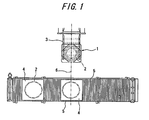
FIG. 1 is a plan view of a place where a crane device is provided. -
FIG. 2 is a side view of the place where the crane device is provided. -
FIG. 3 is a perspective view showing main parts of the crane device. -
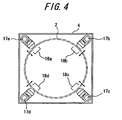
FIG. 4 is a plan view showing movement of arms and claws of the crane device in the packing container. -
Fig. 5 is a side view showing movement of the arm and claw of the crane device. - Hereinbelow, a crane device of the present invention will be described in detail with reference to the drawings.
First, as shown inFIGS. 1 and2 , acrane device 1 of the present invention is provided to be capable of: making reciprocal movements along apath 6 between a position above a lifting-uppoint 3 where a wrappedquartz glass crucible 2 is placed (for example, an endpoint of a transporting conveyor from a wrapping operation) and another position above a putting-down point 5 where apacking container 4 is placed (for example, an intermediate point of a transporting conveyor to a final packing operation); and ascending to/descending from thepath 6 at each of the lifting-uppoint 3 and the putting-down point 5. - As shown in
FIG. 2 , in thecrane device 1,rails 61 forming thepath 6 extend betweencolumns 60 disposed at each of the lifting-uppoint 3 and the putting-down point 5, and aframe 10 is mounted on therails 61 so as to be able to make reciprocal movement along therails 61 by a transfer mechanism 9. As shown inFIG. 3 , supporting plates (three in the shown example) 12, 13, 14 layered by spacing apart from each other are suspendingly connected to theframe 10 by way of anelevation mechanism 11 such that the supporting plates can ascend/descend relative to theframe 10.Link mechanisms 15a-15d are disposed between the supportingplates sliders 16a-16d are provided on the supportingplate 14. Fourarms 17a-17d extending in the ascending/descending direction are attached to the supporting plate by way of thelinkage mechanisms 15a-15d and theslider 16a-16d. - In the present embodiment, as shown in
FIG. 4 , it is important that the fourarms 17a-17d are disposed at the apexes of the quadrangle corresponding to the four corners of a quadrangular-prism-shaped packing container 4, and that the twoarms arms linkage mechanisms 15a-15d and thesliders 16a-16d. Thelinkage mechanisms 15a-15d, driven by a motor M, transfer the aforementioned movements to thearms 17a-17d. Further, each of thearms 17a-17d has aclaw 18a-18d provided at the rear end thereof to extend in the advancing direction of the arm. Yet further,cushion members 19a-19d are wound around an outer periphery of thearms 17a-17d. - As shown in
FIGS. 1 and2 , thecrane device 1 structured as described above is used to lift up thewrapped crucible 2, transfer the raisedwrapped crucible 2 to the quadrangular-prism-shaped packing container 4, and put down thecrucible 2 in thepacking container 4.
Regarding lifting up thewrapped crucible 2 by thecrane device 1, first thecrane device 1 is moved to the lift-uppoint 3, and at this point, the supportingplates frame 10 through theelevation mechanism 11. At this time, thearms 17a-17d and theclaws 18a-18d are caused to retreat to positions that do not interfere with thewrapped crucible 2 by operating thelinkage mechanisms 15a-15d by the motor M. When theclaws 18a-18d at the rear end portions of thearms 17a-17d are lowered and reached a surface of thewrapped crucible 2 at which surface the crucible is placed on a stage, the lowering operation is stopped. Then, thelinkage mechanisms 15a-15d are operated by using the motor M such that thearms 17a-17d advance toward an axial center of thewrapped crucible 2 as shown inFIG. 5 , and this advancing movement of thearms 17a-17d is stopped when theclaws 18a-18d are brought into contact with the vicinity of an edge portion of the bottom surface of thewrapped crucible 2. In the present embodiment, it is important to keep thearms 17a-17d in a state not in contact with the wrap of the crucible, as shown inFIG. 5 , in terms of suppressing contamination at the outer side of the wrap. - Next, the supporting
plates elevation mechanism 11 toward theframe 10, such that thewrapped crucible 2, held at the four corners thereof by theclaws 18a-18d of the fourarms 17a-17d, is lifted up. Thereafter, thecrane device 1 is horizontally moved along thepath 6 to the putting-down point 5 where thepacking container 4 is placed. After thecrane device 1 has reached the putting-down point 5, the supportingplates elevation mechanism 11 from theframe 10 to thepacking container 4. At this time, since thearms 17a-17d are disposed at the apexes of the quadrangle corresponding to the four corners of thepacking container 4, thearms 17a-17d can be adroitly accommodated in largest gap spaces among those created between thewrapped crucible 2 and thepacking container 4, as shown inFIG. 4 . Thearms 17a-17d can each have a relatively large range of movement, as shown in arrow inFIG. 4 , by inserting thearms 17a-17d to these largest gap spaces, whereby thearms 17a-17d and theclaws 18a-18d can advance/retreat with respect to thewrapped crucible 2, as shown inFIG. 5 . - Accordingly, it can be realized that the bottom surface of the
wrapped crucible 2 is supported by theclaws 18a-18d in a state where thearms 17a-17d are not in contact with the wrap of thewrapped crucible 2. Further, since thearms 17a-17d are accommodated at the four corners of thepacking container 4, lengths of the sides of thepacking container 4 can be set closer to a diameter of an opening of the crucible to be accommodated, which contributes to space-efficient designing of thepacking container 4. - The
wrapped crucible 2 is lowered in a state where it is supported as described above. Upon the bottom surface of thecrucible 2 reaching the bottom surface on the inner side of thepacking container 4, the lowering operation of thewrapped crucible 2 is stopped. Then, thelinkage mechanisms 15a-15d are operated such that thearms 17a-17d and theclaws 18a-18d retreat from thewrapped crucible 2, as shown inFIG. 4 . Thereafter, the supportingplates frame 10 through theelevation mechanism 11.
On the other hand, thepacking container 4 having the wrappedcrucible 2 accommodated therein is transferred by, for example, a transporting conveyor for the packing process. A lid for covering the opening of the container is attached to the container, followed by other operations such as roping the container up, in the packing process, and the container is shipped. - Next, examination is made as to the degree of contamination of a quartz glass crucible in a case where the wrapped quartz glass crucible is packed by using the crane device for a wrapped quartz glass crucible according to the present invention as shown in
FIG. 1 . Further, as a Comparative Example, similar examination is made as to a case where a wrapped quartz glass crucible of the same type is manually packed by two operators in the conventional manner. - The degree of contamination of each quartz glass crucible is evaluated by: after packing the wrapped quartz glass crucible, taking the quartz glass crucible out of the wrap in a clean room; attaching adhesive tape to the inner surface of the crucible; removing the attached adhesive tape; visually counting the number of contaminants attached to the adhesive portion of the tape; and calculating the average number of contaminants per unit surface area. For evaluation, the degree of contamination in the case where the wrapped quartz glass crucible is packed by the crane device according to the present invention is calculated as a relative value to the degree of contamination in the case where the wrapped quartz glass crucible is manually packed, which is expressed as index value 100. The smaller relative value represents the smaller degree of contamination. The examination results are shown in Table 1.
[Table 1] Wrapped quartz glass crucible is packed by
using the crane device of the inventionWrapped quartz glass crucible is
manually packedDegree of contamination of surface of crucible 98 100 - As can be clearly understood from the result in Table 1, the contamination of a quartz glass crucible is suppressed, as compared with the conventional manual packing, by using the crane device according to the present invention. Further, laborsaving in packing operation of a quartz glass crucible can be achieved because the quartz glass crucible can be mechanically packed.
Claims (2)
- A crane device (1) provided to be capable of making reciprocal movements along a path (6) between a position above a lifting-up point (3) where a wrapped quartz glass crucible (2) is placed and another position above a putting-down point (5) where a packing container (4) is placed and ascending to descending from the path (6) at each of the lifting-up point (3) and the putting-down point (5), comprising:four arms (17a-17d) extending in the ascend-descend direction and disposed at apexes of a quadrangle such that two arms (17a, 17c; 17b, 17d) paired on a diagonal line of the quadrangle are movable to advance by sliding along the diagonal line to separate from each other; anda claw (18a-18d) provided at a rear end of each arm (17a-17d) to extend in the advancing direction of the arm.
- A method of packing a wrapped quartz glass crucible (2) by lifting up the wrapped quartz glass crucible by a crane device (1), moving the crane device to a quadrangular-prism-shaped packing container (4), and lowering the quartz glass crucible (2) inside the packing container (4), comprising:preparing a crane device (1) having: four arms (17a-17d) extending in the lifting-up direction of the wrapped quartz glass crucible (2) and disposed at apexes of a quadrangle corresponding to the four corners of the packing container (4) such that two arms (17a, 17c; 17b, 17d) paired on a diagonal line of the quadrangle are movable to advance by sliding along the diagonal line to separate from each other; and a claw (18a-18d) provided at a rear end of each arm (17a-17d) to extend in the advancing direction of the arm;supporting the bottom of the wrapped quartz glass crucible (2) by the claws (18a-18d), while the four arms (17a-17d) are kept in a state not in contact with the wrap of the crucible; andlifting up and moving the wrapped quartz glass crucible (2) and then putting it down, thereby loading the quartz glass crucible (2) into the packing container (4).
Applications Claiming Priority (2)
| Application Number | Priority Date | Filing Date | Title |
|---|---|---|---|
| JP2009171485 | 2009-07-22 | ||
| JP2010147511A JP5738549B2 (en) | 2009-07-22 | 2010-06-29 | Crane apparatus for packaged quartz glass crucible and packing method for packaged quartz glass crucible using this apparatus |
Publications (3)
| Publication Number | Publication Date |
|---|---|
| EP2277779A2 EP2277779A2 (en) | 2011-01-26 |
| EP2277779A3 EP2277779A3 (en) | 2012-03-14 |
| EP2277779B1 true EP2277779B1 (en) | 2013-04-17 |
Family
ID=43242827
Family Applications (1)
| Application Number | Title | Priority Date | Filing Date |
|---|---|---|---|
| EP10251308.2A Not-in-force EP2277779B1 (en) | 2009-07-22 | 2010-07-22 | Crane device for wrapped quartz glass crucible and method of packing wrapped quartz glass crucible using the device |
Country Status (6)
| Country | Link |
|---|---|
| US (1) | US20110099952A1 (en) |
| EP (1) | EP2277779B1 (en) |
| JP (1) | JP5738549B2 (en) |
| KR (1) | KR101227038B1 (en) |
| CN (1) | CN101962085B (en) |
| TW (1) | TWI391297B (en) |
Families Citing this family (11)
| Publication number | Priority date | Publication date | Assignee | Title |
|---|---|---|---|---|
| KR20120088488A (en) | 2011-01-31 | 2012-08-08 | 한국전자통신연구원 | method for storing temporal motion vector and apparatus using the same |
| CN102310990A (en) * | 2011-03-09 | 2012-01-11 | 维苏威太阳能坩埚(苏州)有限公司 | Device for transporting crucibles |
| CN102424160A (en) * | 2011-08-18 | 2012-04-25 | 德清县建明坩埚厂 | Crucible packing car |
| CN102424161A (en) * | 2011-08-18 | 2012-04-25 | 德清县建明坩埚厂 | Crucible packing vehicle |
| CN102400208A (en) * | 2011-11-15 | 2012-04-04 | 宁夏日晶新能源装备股份有限公司 | Crucible withdrawing device of single crystal furnace |
| CN105253350B (en) * | 2015-09-30 | 2018-02-27 | 安钢集团华德重工装备有限公司 | A kind of special packing apparatus of steel band and application method |
| CN109573853B (en) * | 2019-01-17 | 2023-12-22 | 吉林大学 | A three-section arm type translational lifting and transporting device |
| CN113003210A (en) * | 2021-03-24 | 2021-06-22 | 河南高柏智能搬运机械有限公司 | Linkage type clasping clamp |
| CN115648260A (en) * | 2022-09-27 | 2023-01-31 | 浙江晶盛机电股份有限公司 | Single crystal furnace ingot manipulator device and using method |
| CN119111273A (en) * | 2024-09-24 | 2024-12-13 | 中国石油大学(北京) | Intelligent reconfigurable cabbage bundling robot |
| CN119528051B (en) * | 2024-11-27 | 2025-10-24 | 常州裕能石英科技有限公司 | A linear crucible lifting device |
Family Cites Families (36)
| Publication number | Priority date | Publication date | Assignee | Title |
|---|---|---|---|---|
| US3231303A (en) * | 1963-04-01 | 1966-01-25 | Robert G Letourneau | Rotatable grapple |
| US3202449A (en) * | 1963-04-29 | 1965-08-24 | Jerome H Lemelson | Article manipulation device |
| US3856342A (en) * | 1973-05-14 | 1974-12-24 | J Kelly | Pantographic cargo hoist |
| US4252496A (en) * | 1976-10-29 | 1981-02-24 | Williams John A | Hydraulic clamp for trays of canned beverages |
| JPS5761487A (en) * | 1980-09-30 | 1982-04-13 | Fujitsu Fanuc Ltd | Hand for industrial robot |
| EP0142420A3 (en) * | 1983-10-28 | 1986-12-17 | "ATECMI", S.A. dite: | Method of picking up a layer of containers and gripper to transfer a complete layer of containers |
| FR2576007B1 (en) * | 1985-01-17 | 1988-04-29 | Lebre Charles | TELESCOPIC GRIPPING APPARATUS FOR LIFTING DRUMS OR OTHER OBJECTS WITH A CIRCULAR SECTION |
| US5141274A (en) * | 1988-02-09 | 1992-08-25 | Galpin Research, Limited Partnership | Apparatus for grasping and handling cubes of stacked printed products |
| JPH0281891A (en) * | 1988-09-16 | 1990-03-22 | Chubu Electric Power Co Inc | Drum clamp device |
| JPH0796407B2 (en) * | 1988-10-12 | 1995-10-18 | 三友工業株式会社 | Multiple workpiece chucking device |
| DE4039167A1 (en) * | 1990-12-05 | 1992-06-11 | Mannesmann Ag | Gripper with several elements for moving objects - has direct drive for each element mounted star fashion in common base element |
| JP2595398Y2 (en) * | 1992-05-20 | 1999-05-31 | 光洋精工株式会社 | Bearing lifting jig |
| JP3278786B2 (en) * | 1992-12-26 | 2002-04-30 | 三菱マテリアルクォーツ株式会社 | Quartz crucible for pulling silicon single crystal and its manufacturing method |
| JPH0761583A (en) * | 1993-08-30 | 1995-03-07 | Iseki & Co Ltd | Cylindrical article lifting device |
| JP3158328B2 (en) * | 1993-12-20 | 2001-04-23 | 三菱マテリアル株式会社 | Method and apparatus for incorporating raw materials for single crystal pulling apparatus |
| JPH07187560A (en) * | 1993-12-27 | 1995-07-25 | Murata Mach Ltd | Article gripping device of overhead traveling vehicle |
| JP3435498B2 (en) * | 1993-12-29 | 2003-08-11 | 東芝セラミックス株式会社 | Method of mounting crucible assembly to lifting device and device therefor |
| JPH07276282A (en) * | 1994-02-21 | 1995-10-24 | Narasaki Sangyo Kk | Hand to transport masslike body to be easily damaged |
| GB9608251D0 (en) * | 1996-04-20 | 1996-06-26 | Elopak Systems | Improvements in or relating to gripping devices |
| JP3313296B2 (en) * | 1996-05-14 | 2002-08-12 | ティー・シー・エム株式会社 | Lifting and moving equipment |
| JPH107373A (en) * | 1996-06-25 | 1998-01-13 | Ishikawajima Harima Heavy Ind Co Ltd | Large container suspension device |
| KR200199421Y1 (en) * | 1996-08-14 | 2000-11-01 | 이구택 | Checking the moving direction of the crane's coil and preventing the collision |
| JP3594172B2 (en) * | 1998-05-19 | 2004-11-24 | 東芝セラミックス株式会社 | Mounting device and replacement device for crucible assembly or hot zone member, and drive control method for crucible assembly replacement device |
| JPH11349276A (en) * | 1998-06-10 | 1999-12-21 | Kokan Drum Co Ltd | Can lifting tool |
| JP2000016748A (en) * | 1998-07-03 | 2000-01-18 | Sumitomo Metal Mining Co Ltd | Hanging material for plate |
| JP4394190B2 (en) * | 1999-01-28 | 2010-01-06 | ジャパンスーパークォーツ株式会社 | Quartz crucible wrapping equipment |
| JP4424785B2 (en) * | 1999-06-28 | 2010-03-03 | ジャパンスーパークォーツ株式会社 | Quartz crucible cleaning and sealing device and high purity quartz crucible |
| JP4994527B2 (en) * | 2000-07-13 | 2012-08-08 | Sumco Techxiv株式会社 | Crucible handling device and crucible handling kit |
| JP2002060177A (en) | 2000-08-17 | 2002-02-26 | Babcock Hitachi Kk | Upper lid lift device |
| JP4048409B2 (en) * | 2001-10-22 | 2008-02-20 | 株式会社ダイフク | Transport equipment |
| JP4076416B2 (en) * | 2002-09-20 | 2008-04-16 | コバレントマテリアル株式会社 | Quartz crucible and its manufacturing method |
| US7537427B2 (en) * | 2002-12-04 | 2009-05-26 | Tygard Machine & Manufacturing Company | Clamping apparatus |
| JP2004238147A (en) * | 2003-02-06 | 2004-08-26 | Okura Yusoki Co Ltd | Holding device and transfer machine |
| US20070001472A1 (en) * | 2003-03-28 | 2007-01-04 | Hildebrand John J Jr | Gripping arm assembly for loading a filled inner container into an outer container |
| CN201010450Y (en) * | 2007-01-19 | 2008-01-23 | 太原英博科贸有限公司 | Clamp crane |
| JP4974770B2 (en) * | 2007-06-04 | 2012-07-11 | コバレントマテリアル株式会社 | How to replace the crucible |
-
2010
- 2010-06-29 JP JP2010147511A patent/JP5738549B2/en active Active
- 2010-07-21 KR KR1020100070675A patent/KR101227038B1/en not_active Expired - Fee Related
- 2010-07-21 US US12/804,456 patent/US20110099952A1/en not_active Abandoned
- 2010-07-22 EP EP10251308.2A patent/EP2277779B1/en not_active Not-in-force
- 2010-07-22 CN CN2010102354214A patent/CN101962085B/en active Active
- 2010-07-22 TW TW099124176A patent/TWI391297B/en not_active IP Right Cessation
Also Published As
| Publication number | Publication date |
|---|---|
| EP2277779A2 (en) | 2011-01-26 |
| KR101227038B1 (en) | 2013-01-28 |
| JP5738549B2 (en) | 2015-06-24 |
| KR20110009636A (en) | 2011-01-28 |
| TWI391297B (en) | 2013-04-01 |
| CN101962085A (en) | 2011-02-02 |
| EP2277779A3 (en) | 2012-03-14 |
| JP2011042503A (en) | 2011-03-03 |
| TW201103821A (en) | 2011-02-01 |
| CN101962085B (en) | 2012-09-19 |
| US20110099952A1 (en) | 2011-05-05 |
Similar Documents
| Publication | Publication Date | Title |
|---|---|---|
| EP2277779A2 (en) | Crane device for wrapped quartz glass crucible and method of packing wrapped quartz glass crucible using the device | |
| JP4003882B2 (en) | Substrate transfer system | |
| CA2938850C (en) | System and method for palletizing | |
| WO2012086164A1 (en) | Transportation robot, substrate transportation method therefor, and substrate transportation relay apparatus | |
| KR100906294B1 (en) | Automatic packaging device for cassette for semiconductor wafer storage and automatic packaging method using the same | |
| JP5605791B2 (en) | Nori extraction equipment | |
| KR102171038B1 (en) | Taping apparatus having lifting and rotating unit for packing box | |
| CN212371733U (en) | Automatic feeding machine for cutting metal parts | |
| CN111470102B (en) | Cigarette box forming equipment and forming method | |
| JP4394190B2 (en) | Quartz crucible wrapping equipment | |
| JP5937189B2 (en) | Crane apparatus for packaged quartz glass crucible and packing method for packaged quartz glass crucible using this apparatus | |
| CN217933723U (en) | SMIF wafer box wafer sensing device | |
| CN117476525B (en) | Wafer box equipment of uncapping | |
| CN117228110A (en) | Cigarette small box packaging paper unbinding feeding system and unbinding feeding method | |
| CN111674641A (en) | Facial mask production equipment for packing | |
| CN102270565B (en) | Substrate processing device | |
| KR102169607B1 (en) | Taping apparatus for packing box with tension arm | |
| CN209921686U (en) | Sanitary appliance packaging device | |
| CN201348993Y (en) | Wafer temporary storage device | |
| CN113097554B (en) | Automatic vacuum-pumping packaging equipment | |
| CN113859967A (en) | Feeding machine for battery baking | |
| CN221274286U (en) | Tray of duplex position automatic feeding machine | |
| TWI897140B (en) | Reticle Box Storage Device | |
| CN214690345U (en) | Packing box winding and packaging device | |
| CN219575587U (en) | Wafer box turning and rewinding machine |
Legal Events
| Date | Code | Title | Description |
|---|---|---|---|
| PUAI | Public reference made under article 153(3) epc to a published international application that has entered the european phase |
Free format text: ORIGINAL CODE: 0009012 |
|
| AK | Designated contracting states |
Kind code of ref document: A2 Designated state(s): AL AT BE BG CH CY CZ DE DK EE ES FI FR GB GR HR HU IE IS IT LI LT LU LV MC MK MT NL NO PL PT RO SE SI SK SM TR |
|
| AX | Request for extension of the european patent |
Extension state: BA ME RS |
|
| PUAL | Search report despatched |
Free format text: ORIGINAL CODE: 0009013 |
|
| AK | Designated contracting states |
Kind code of ref document: A3 Designated state(s): AL AT BE BG CH CY CZ DE DK EE ES FI FR GB GR HR HU IE IS IT LI LT LU LV MC MK MT NL NO PL PT RO SE SI SK SM TR |
|
| AX | Request for extension of the european patent |
Extension state: BA ME RS |
|
| RIC1 | Information provided on ipc code assigned before grant |
Ipc: B65B 5/04 20060101AFI20120203BHEP Ipc: C30B 15/30 20060101ALI20120203BHEP Ipc: B65B 35/16 20060101ALI20120203BHEP |
|
| 17P | Request for examination filed |
Effective date: 20120911 |
|
| GRAP | Despatch of communication of intention to grant a patent |
Free format text: ORIGINAL CODE: EPIDOSNIGR1 |
|
| RIC1 | Information provided on ipc code assigned before grant |
Ipc: C30B 35/00 20060101ALI20121005BHEP Ipc: B65B 5/04 20060101AFI20121005BHEP Ipc: B65B 35/16 20060101ALI20121005BHEP |
|
| GRAS | Grant fee paid |
Free format text: ORIGINAL CODE: EPIDOSNIGR3 |
|
| GRAA | (expected) grant |
Free format text: ORIGINAL CODE: 0009210 |
|
| AK | Designated contracting states |
Kind code of ref document: B1 Designated state(s): AL AT BE BG CH CY CZ DE DK EE ES FI FR GB GR HR HU IE IS IT LI LT LU LV MC MK MT NL NO PL PT RO SE SI SK SM TR |
|
| REG | Reference to a national code |
Ref country code: GB Ref legal event code: FG4D |
|
| REG | Reference to a national code |
Ref country code: CH Ref legal event code: EP |
|
| REG | Reference to a national code |
Ref country code: IE Ref legal event code: FG4D |
|
| REG | Reference to a national code |
Ref country code: AT Ref legal event code: REF Ref document number: 607126 Country of ref document: AT Kind code of ref document: T Effective date: 20130515 |
|
| REG | Reference to a national code |
Ref country code: DE Ref legal event code: R096 Ref document number: 602010006254 Country of ref document: DE Effective date: 20130613 |
|
| REG | Reference to a national code |
Ref country code: DE Ref legal event code: R082 Ref document number: 602010006254 Country of ref document: DE Representative=s name: GULDE & PARTNER PATENT- UND RECHTSANWALTSKANZL, DE |
|
| REG | Reference to a national code |
Ref country code: AT Ref legal event code: MK05 Ref document number: 607126 Country of ref document: AT Kind code of ref document: T Effective date: 20130417 |
|
| REG | Reference to a national code |
Ref country code: LT Ref legal event code: MG4D |
|
| REG | Reference to a national code |
Ref country code: NL Ref legal event code: VDEP Effective date: 20130417 |
|
| PG25 | Lapsed in a contracting state [announced via postgrant information from national office to epo] |
Ref country code: FI Free format text: LAPSE BECAUSE OF FAILURE TO SUBMIT A TRANSLATION OF THE DESCRIPTION OR TO PAY THE FEE WITHIN THE PRESCRIBED TIME-LIMIT Effective date: 20130417 Ref country code: BE Free format text: LAPSE BECAUSE OF FAILURE TO SUBMIT A TRANSLATION OF THE DESCRIPTION OR TO PAY THE FEE WITHIN THE PRESCRIBED TIME-LIMIT Effective date: 20130417 Ref country code: NO Free format text: LAPSE BECAUSE OF FAILURE TO SUBMIT A TRANSLATION OF THE DESCRIPTION OR TO PAY THE FEE WITHIN THE PRESCRIBED TIME-LIMIT Effective date: 20130717 Ref country code: IS Free format text: LAPSE BECAUSE OF FAILURE TO SUBMIT A TRANSLATION OF THE DESCRIPTION OR TO PAY THE FEE WITHIN THE PRESCRIBED TIME-LIMIT Effective date: 20130817 Ref country code: PT Free format text: LAPSE BECAUSE OF FAILURE TO SUBMIT A TRANSLATION OF THE DESCRIPTION OR TO PAY THE FEE WITHIN THE PRESCRIBED TIME-LIMIT Effective date: 20130819 Ref country code: GR Free format text: LAPSE BECAUSE OF FAILURE TO SUBMIT A TRANSLATION OF THE DESCRIPTION OR TO PAY THE FEE WITHIN THE PRESCRIBED TIME-LIMIT Effective date: 20130718 Ref country code: ES Free format text: LAPSE BECAUSE OF FAILURE TO SUBMIT A TRANSLATION OF THE DESCRIPTION OR TO PAY THE FEE WITHIN THE PRESCRIBED TIME-LIMIT Effective date: 20130728 Ref country code: SE Free format text: LAPSE BECAUSE OF FAILURE TO SUBMIT A TRANSLATION OF THE DESCRIPTION OR TO PAY THE FEE WITHIN THE PRESCRIBED TIME-LIMIT Effective date: 20130417 Ref country code: SI Free format text: LAPSE BECAUSE OF FAILURE TO SUBMIT A TRANSLATION OF THE DESCRIPTION OR TO PAY THE FEE WITHIN THE PRESCRIBED TIME-LIMIT Effective date: 20130417 Ref country code: LT Free format text: LAPSE BECAUSE OF FAILURE TO SUBMIT A TRANSLATION OF THE DESCRIPTION OR TO PAY THE FEE WITHIN THE PRESCRIBED TIME-LIMIT Effective date: 20130417 Ref country code: AT Free format text: LAPSE BECAUSE OF FAILURE TO SUBMIT A TRANSLATION OF THE DESCRIPTION OR TO PAY THE FEE WITHIN THE PRESCRIBED TIME-LIMIT Effective date: 20130417 |
|
| PG25 | Lapsed in a contracting state [announced via postgrant information from national office to epo] |
Ref country code: LV Free format text: LAPSE BECAUSE OF FAILURE TO SUBMIT A TRANSLATION OF THE DESCRIPTION OR TO PAY THE FEE WITHIN THE PRESCRIBED TIME-LIMIT Effective date: 20130417 Ref country code: HR Free format text: LAPSE BECAUSE OF FAILURE TO SUBMIT A TRANSLATION OF THE DESCRIPTION OR TO PAY THE FEE WITHIN THE PRESCRIBED TIME-LIMIT Effective date: 20130417 Ref country code: BG Free format text: LAPSE BECAUSE OF FAILURE TO SUBMIT A TRANSLATION OF THE DESCRIPTION OR TO PAY THE FEE WITHIN THE PRESCRIBED TIME-LIMIT Effective date: 20130717 Ref country code: PL Free format text: LAPSE BECAUSE OF FAILURE TO SUBMIT A TRANSLATION OF THE DESCRIPTION OR TO PAY THE FEE WITHIN THE PRESCRIBED TIME-LIMIT Effective date: 20130417 Ref country code: CY Free format text: LAPSE BECAUSE OF FAILURE TO SUBMIT A TRANSLATION OF THE DESCRIPTION OR TO PAY THE FEE WITHIN THE PRESCRIBED TIME-LIMIT Effective date: 20130417 |
|
| PG25 | Lapsed in a contracting state [announced via postgrant information from national office to epo] |
Ref country code: SK Free format text: LAPSE BECAUSE OF FAILURE TO SUBMIT A TRANSLATION OF THE DESCRIPTION OR TO PAY THE FEE WITHIN THE PRESCRIBED TIME-LIMIT Effective date: 20130417 Ref country code: DK Free format text: LAPSE BECAUSE OF FAILURE TO SUBMIT A TRANSLATION OF THE DESCRIPTION OR TO PAY THE FEE WITHIN THE PRESCRIBED TIME-LIMIT Effective date: 20130417 Ref country code: EE Free format text: LAPSE BECAUSE OF FAILURE TO SUBMIT A TRANSLATION OF THE DESCRIPTION OR TO PAY THE FEE WITHIN THE PRESCRIBED TIME-LIMIT Effective date: 20130417 Ref country code: CZ Free format text: LAPSE BECAUSE OF FAILURE TO SUBMIT A TRANSLATION OF THE DESCRIPTION OR TO PAY THE FEE WITHIN THE PRESCRIBED TIME-LIMIT Effective date: 20130417 |
|
| PLBE | No opposition filed within time limit |
Free format text: ORIGINAL CODE: 0009261 |
|
| STAA | Information on the status of an ep patent application or granted ep patent |
Free format text: STATUS: NO OPPOSITION FILED WITHIN TIME LIMIT |
|
| PG25 | Lapsed in a contracting state [announced via postgrant information from national office to epo] |
Ref country code: IT Free format text: LAPSE BECAUSE OF FAILURE TO SUBMIT A TRANSLATION OF THE DESCRIPTION OR TO PAY THE FEE WITHIN THE PRESCRIBED TIME-LIMIT Effective date: 20130417 Ref country code: NL Free format text: LAPSE BECAUSE OF FAILURE TO SUBMIT A TRANSLATION OF THE DESCRIPTION OR TO PAY THE FEE WITHIN THE PRESCRIBED TIME-LIMIT Effective date: 20130417 Ref country code: RO Free format text: LAPSE BECAUSE OF FAILURE TO SUBMIT A TRANSLATION OF THE DESCRIPTION OR TO PAY THE FEE WITHIN THE PRESCRIBED TIME-LIMIT Effective date: 20130417 Ref country code: MC Free format text: LAPSE BECAUSE OF FAILURE TO SUBMIT A TRANSLATION OF THE DESCRIPTION OR TO PAY THE FEE WITHIN THE PRESCRIBED TIME-LIMIT Effective date: 20130417 |
|
| 26N | No opposition filed |
Effective date: 20140120 |
|
| REG | Reference to a national code |
Ref country code: IE Ref legal event code: MM4A |
|
| REG | Reference to a national code |
Ref country code: DE Ref legal event code: R097 Ref document number: 602010006254 Country of ref document: DE Effective date: 20140120 |
|
| PG25 | Lapsed in a contracting state [announced via postgrant information from national office to epo] |
Ref country code: IE Free format text: LAPSE BECAUSE OF NON-PAYMENT OF DUE FEES Effective date: 20130722 |
|
| REG | Reference to a national code |
Ref country code: CH Ref legal event code: PL |
|
| PG25 | Lapsed in a contracting state [announced via postgrant information from national office to epo] |
Ref country code: CH Free format text: LAPSE BECAUSE OF NON-PAYMENT OF DUE FEES Effective date: 20140731 Ref country code: LI Free format text: LAPSE BECAUSE OF NON-PAYMENT OF DUE FEES Effective date: 20140731 |
|
| PG25 | Lapsed in a contracting state [announced via postgrant information from national office to epo] |
Ref country code: SM Free format text: LAPSE BECAUSE OF FAILURE TO SUBMIT A TRANSLATION OF THE DESCRIPTION OR TO PAY THE FEE WITHIN THE PRESCRIBED TIME-LIMIT Effective date: 20130417 |
|
| REG | Reference to a national code |
Ref country code: FR Ref legal event code: PLFP Year of fee payment: 6 |
|
| PG25 | Lapsed in a contracting state [announced via postgrant information from national office to epo] |
Ref country code: MT Free format text: LAPSE BECAUSE OF FAILURE TO SUBMIT A TRANSLATION OF THE DESCRIPTION OR TO PAY THE FEE WITHIN THE PRESCRIBED TIME-LIMIT Effective date: 20130417 Ref country code: TR Free format text: LAPSE BECAUSE OF FAILURE TO SUBMIT A TRANSLATION OF THE DESCRIPTION OR TO PAY THE FEE WITHIN THE PRESCRIBED TIME-LIMIT Effective date: 20130417 |
|
| PG25 | Lapsed in a contracting state [announced via postgrant information from national office to epo] |
Ref country code: LU Free format text: LAPSE BECAUSE OF NON-PAYMENT OF DUE FEES Effective date: 20130722 Ref country code: MK Free format text: LAPSE BECAUSE OF FAILURE TO SUBMIT A TRANSLATION OF THE DESCRIPTION OR TO PAY THE FEE WITHIN THE PRESCRIBED TIME-LIMIT Effective date: 20130417 Ref country code: HU Free format text: LAPSE BECAUSE OF FAILURE TO SUBMIT A TRANSLATION OF THE DESCRIPTION OR TO PAY THE FEE WITHIN THE PRESCRIBED TIME-LIMIT; INVALID AB INITIO Effective date: 20100722 |
|
| REG | Reference to a national code |
Ref country code: FR Ref legal event code: PLFP Year of fee payment: 7 |
|
| REG | Reference to a national code |
Ref country code: FR Ref legal event code: PLFP Year of fee payment: 8 |
|
| REG | Reference to a national code |
Ref country code: FR Ref legal event code: PLFP Year of fee payment: 9 |
|
| PG25 | Lapsed in a contracting state [announced via postgrant information from national office to epo] |
Ref country code: AL Free format text: LAPSE BECAUSE OF FAILURE TO SUBMIT A TRANSLATION OF THE DESCRIPTION OR TO PAY THE FEE WITHIN THE PRESCRIBED TIME-LIMIT Effective date: 20130417 |
|
| REG | Reference to a national code |
Ref country code: DE Ref legal event code: R082 Ref document number: 602010006254 Country of ref document: DE Representative=s name: KRAUS & LEDERER PARTGMBB, DE Ref country code: DE Ref legal event code: R081 Ref document number: 602010006254 Country of ref document: DE Owner name: SUMCO CORPORATION, JP Free format text: FORMER OWNER: JAPAN SUPER QUARTZ CORPORATION, AKITA-SHI, JP Ref country code: DE Ref legal event code: R082 Ref document number: 602010006254 Country of ref document: DE Representative=s name: KRAUS & WEISERT PATENTANWAELTE PARTGMBB, DE |
|
| PGFP | Annual fee paid to national office [announced via postgrant information from national office to epo] |
Ref country code: GB Payment date: 20220721 Year of fee payment: 13 |
|
| PGFP | Annual fee paid to national office [announced via postgrant information from national office to epo] |
Ref country code: FR Payment date: 20220720 Year of fee payment: 13 |
|
| GBPC | Gb: european patent ceased through non-payment of renewal fee |
Effective date: 20230722 |
|
| PG25 | Lapsed in a contracting state [announced via postgrant information from national office to epo] |
Ref country code: GB Free format text: LAPSE BECAUSE OF NON-PAYMENT OF DUE FEES Effective date: 20230722 |
|
| PG25 | Lapsed in a contracting state [announced via postgrant information from national office to epo] |
Ref country code: FR Free format text: LAPSE BECAUSE OF NON-PAYMENT OF DUE FEES Effective date: 20230731 |
|
| PGFP | Annual fee paid to national office [announced via postgrant information from national office to epo] |
Ref country code: DE Payment date: 20240719 Year of fee payment: 15 |
|
| REG | Reference to a national code |
Ref country code: DE Ref legal event code: R119 Ref document number: 602010006254 Country of ref document: DE |
|
| PG25 | Lapsed in a contracting state [announced via postgrant information from national office to epo] |
Ref country code: DE Free format text: LAPSE BECAUSE OF NON-PAYMENT OF DUE FEES Effective date: 20260203 |