EP2277685A1 - Verfahren zum Verbinden von Teilen aus einem vulkanisierten Gummiwerkstoff und/oder aus Metall mittels einer Klebefolie - Google Patents
Verfahren zum Verbinden von Teilen aus einem vulkanisierten Gummiwerkstoff und/oder aus Metall mittels einer Klebefolie Download PDFInfo
- Publication number
- EP2277685A1 EP2277685A1 EP20100168496 EP10168496A EP2277685A1 EP 2277685 A1 EP2277685 A1 EP 2277685A1 EP 20100168496 EP20100168496 EP 20100168496 EP 10168496 A EP10168496 A EP 10168496A EP 2277685 A1 EP2277685 A1 EP 2277685A1
- Authority
- EP
- European Patent Office
- Prior art keywords
- parts
- composite
- rubber
- metal
- adhesive film
- Prior art date
- Legal status (The legal status is an assumption and is not a legal conclusion. Google has not performed a legal analysis and makes no representation as to the accuracy of the status listed.)
- Withdrawn
Links
Images


Classifications
-
- B—PERFORMING OPERATIONS; TRANSPORTING
- B29—WORKING OF PLASTICS; WORKING OF SUBSTANCES IN A PLASTIC STATE IN GENERAL
- B29C—SHAPING OR JOINING OF PLASTICS; SHAPING OF MATERIAL IN A PLASTIC STATE, NOT OTHERWISE PROVIDED FOR; AFTER-TREATMENT OF THE SHAPED PRODUCTS, e.g. REPAIRING
- B29C65/00—Joining or sealing of preformed parts, e.g. welding of plastics materials; Apparatus therefor
- B29C65/02—Joining or sealing of preformed parts, e.g. welding of plastics materials; Apparatus therefor by heating, with or without pressure
- B29C65/18—Joining or sealing of preformed parts, e.g. welding of plastics materials; Apparatus therefor by heating, with or without pressure using heated tools
- B29C65/20—Joining or sealing of preformed parts, e.g. welding of plastics materials; Apparatus therefor by heating, with or without pressure using heated tools with direct contact, e.g. using "mirror"
-
- B—PERFORMING OPERATIONS; TRANSPORTING
- B29—WORKING OF PLASTICS; WORKING OF SUBSTANCES IN A PLASTIC STATE IN GENERAL
- B29C—SHAPING OR JOINING OF PLASTICS; SHAPING OF MATERIAL IN A PLASTIC STATE, NOT OTHERWISE PROVIDED FOR; AFTER-TREATMENT OF THE SHAPED PRODUCTS, e.g. REPAIRING
- B29C37/00—Component parts, details, accessories or auxiliary operations, not covered by group B29C33/00 or B29C35/00
- B29C37/02—Deburring or deflashing
- B29C37/04—Deburring or deflashing of welded articles, e.g. deburring or deflashing in combination with welding
-
- B—PERFORMING OPERATIONS; TRANSPORTING
- B29—WORKING OF PLASTICS; WORKING OF SUBSTANCES IN A PLASTIC STATE IN GENERAL
- B29C—SHAPING OR JOINING OF PLASTICS; SHAPING OF MATERIAL IN A PLASTIC STATE, NOT OTHERWISE PROVIDED FOR; AFTER-TREATMENT OF THE SHAPED PRODUCTS, e.g. REPAIRING
- B29C65/00—Joining or sealing of preformed parts, e.g. welding of plastics materials; Apparatus therefor
- B29C65/48—Joining or sealing of preformed parts, e.g. welding of plastics materials; Apparatus therefor using adhesives, i.e. using supplementary joining material; solvent bonding
- B29C65/4805—Joining or sealing of preformed parts, e.g. welding of plastics materials; Apparatus therefor using adhesives, i.e. using supplementary joining material; solvent bonding characterised by the type of adhesives
- B29C65/481—Non-reactive adhesives, e.g. physically hardening adhesives
- B29C65/4815—Hot melt adhesives, e.g. thermoplastic adhesives
-
- B—PERFORMING OPERATIONS; TRANSPORTING
- B29—WORKING OF PLASTICS; WORKING OF SUBSTANCES IN A PLASTIC STATE IN GENERAL
- B29C—SHAPING OR JOINING OF PLASTICS; SHAPING OF MATERIAL IN A PLASTIC STATE, NOT OTHERWISE PROVIDED FOR; AFTER-TREATMENT OF THE SHAPED PRODUCTS, e.g. REPAIRING
- B29C65/00—Joining or sealing of preformed parts, e.g. welding of plastics materials; Apparatus therefor
- B29C65/48—Joining or sealing of preformed parts, e.g. welding of plastics materials; Apparatus therefor using adhesives, i.e. using supplementary joining material; solvent bonding
- B29C65/50—Joining or sealing of preformed parts, e.g. welding of plastics materials; Apparatus therefor using adhesives, i.e. using supplementary joining material; solvent bonding using adhesive tape, e.g. thermoplastic tape; using threads or the like
- B29C65/5057—Joining or sealing of preformed parts, e.g. welding of plastics materials; Apparatus therefor using adhesives, i.e. using supplementary joining material; solvent bonding using adhesive tape, e.g. thermoplastic tape; using threads or the like positioned between the surfaces to be joined
-
- B—PERFORMING OPERATIONS; TRANSPORTING
- B29—WORKING OF PLASTICS; WORKING OF SUBSTANCES IN A PLASTIC STATE IN GENERAL
- B29C—SHAPING OR JOINING OF PLASTICS; SHAPING OF MATERIAL IN A PLASTIC STATE, NOT OTHERWISE PROVIDED FOR; AFTER-TREATMENT OF THE SHAPED PRODUCTS, e.g. REPAIRING
- B29C66/00—General aspects of processes or apparatus for joining preformed parts
- B29C66/01—General aspects dealing with the joint area or with the area to be joined
- B29C66/05—Particular design of joint configurations
- B29C66/10—Particular design of joint configurations particular design of the joint cross-sections
- B29C66/11—Joint cross-sections comprising a single joint-segment, i.e. one of the parts to be joined comprising a single joint-segment in the joint cross-section
- B29C66/112—Single lapped joints
- B29C66/1122—Single lap to lap joints, i.e. overlap joints
-
- B—PERFORMING OPERATIONS; TRANSPORTING
- B29—WORKING OF PLASTICS; WORKING OF SUBSTANCES IN A PLASTIC STATE IN GENERAL
- B29C—SHAPING OR JOINING OF PLASTICS; SHAPING OF MATERIAL IN A PLASTIC STATE, NOT OTHERWISE PROVIDED FOR; AFTER-TREATMENT OF THE SHAPED PRODUCTS, e.g. REPAIRING
- B29C66/00—General aspects of processes or apparatus for joining preformed parts
- B29C66/01—General aspects dealing with the joint area or with the area to be joined
- B29C66/05—Particular design of joint configurations
- B29C66/10—Particular design of joint configurations particular design of the joint cross-sections
- B29C66/11—Joint cross-sections comprising a single joint-segment, i.e. one of the parts to be joined comprising a single joint-segment in the joint cross-section
- B29C66/114—Single butt joints
- B29C66/1142—Single butt to butt joints
-
- B—PERFORMING OPERATIONS; TRANSPORTING
- B29—WORKING OF PLASTICS; WORKING OF SUBSTANCES IN A PLASTIC STATE IN GENERAL
- B29C—SHAPING OR JOINING OF PLASTICS; SHAPING OF MATERIAL IN A PLASTIC STATE, NOT OTHERWISE PROVIDED FOR; AFTER-TREATMENT OF THE SHAPED PRODUCTS, e.g. REPAIRING
- B29C66/00—General aspects of processes or apparatus for joining preformed parts
- B29C66/40—General aspects of joining substantially flat articles, e.g. plates, sheets or web-like materials; Making flat seams in tubular or hollow articles; Joining single elements to substantially flat surfaces
- B29C66/41—Joining substantially flat articles ; Making flat seams in tubular or hollow articles
- B29C66/43—Joining a relatively small portion of the surface of said articles
-
- B—PERFORMING OPERATIONS; TRANSPORTING
- B29—WORKING OF PLASTICS; WORKING OF SUBSTANCES IN A PLASTIC STATE IN GENERAL
- B29C—SHAPING OR JOINING OF PLASTICS; SHAPING OF MATERIAL IN A PLASTIC STATE, NOT OTHERWISE PROVIDED FOR; AFTER-TREATMENT OF THE SHAPED PRODUCTS, e.g. REPAIRING
- B29C66/00—General aspects of processes or apparatus for joining preformed parts
- B29C66/40—General aspects of joining substantially flat articles, e.g. plates, sheets or web-like materials; Making flat seams in tubular or hollow articles; Joining single elements to substantially flat surfaces
- B29C66/41—Joining substantially flat articles ; Making flat seams in tubular or hollow articles
- B29C66/45—Joining of substantially the whole surface of the articles
- B29C66/452—Joining of substantially the whole surface of the articles the article having a disc form, e.g. making CDs or DVDs
-
- B—PERFORMING OPERATIONS; TRANSPORTING
- B29—WORKING OF PLASTICS; WORKING OF SUBSTANCES IN A PLASTIC STATE IN GENERAL
- B29C—SHAPING OR JOINING OF PLASTICS; SHAPING OF MATERIAL IN A PLASTIC STATE, NOT OTHERWISE PROVIDED FOR; AFTER-TREATMENT OF THE SHAPED PRODUCTS, e.g. REPAIRING
- B29C66/00—General aspects of processes or apparatus for joining preformed parts
- B29C66/70—General aspects of processes or apparatus for joining preformed parts characterised by the composition, physical properties or the structure of the material of the parts to be joined; Joining with non-plastics material
- B29C66/71—General aspects of processes or apparatus for joining preformed parts characterised by the composition, physical properties or the structure of the material of the parts to be joined; Joining with non-plastics material characterised by the composition of the plastics material of the parts to be joined
-
- B—PERFORMING OPERATIONS; TRANSPORTING
- B29—WORKING OF PLASTICS; WORKING OF SUBSTANCES IN A PLASTIC STATE IN GENERAL
- B29C—SHAPING OR JOINING OF PLASTICS; SHAPING OF MATERIAL IN A PLASTIC STATE, NOT OTHERWISE PROVIDED FOR; AFTER-TREATMENT OF THE SHAPED PRODUCTS, e.g. REPAIRING
- B29C66/00—General aspects of processes or apparatus for joining preformed parts
- B29C66/70—General aspects of processes or apparatus for joining preformed parts characterised by the composition, physical properties or the structure of the material of the parts to be joined; Joining with non-plastics material
- B29C66/73—General aspects of processes or apparatus for joining preformed parts characterised by the composition, physical properties or the structure of the material of the parts to be joined; Joining with non-plastics material characterised by the intensive physical properties of the material of the parts to be joined, by the optical properties of the material of the parts to be joined, by the extensive physical properties of the parts to be joined, by the state of the material of the parts to be joined or by the material of the parts to be joined being a thermoplastic or a thermoset
- B29C66/737—General aspects of processes or apparatus for joining preformed parts characterised by the composition, physical properties or the structure of the material of the parts to be joined; Joining with non-plastics material characterised by the intensive physical properties of the material of the parts to be joined, by the optical properties of the material of the parts to be joined, by the extensive physical properties of the parts to be joined, by the state of the material of the parts to be joined or by the material of the parts to be joined being a thermoplastic or a thermoset characterised by the state of the material of the parts to be joined
- B29C66/7375—General aspects of processes or apparatus for joining preformed parts characterised by the composition, physical properties or the structure of the material of the parts to be joined; Joining with non-plastics material characterised by the intensive physical properties of the material of the parts to be joined, by the optical properties of the material of the parts to be joined, by the extensive physical properties of the parts to be joined, by the state of the material of the parts to be joined or by the material of the parts to be joined being a thermoplastic or a thermoset characterised by the state of the material of the parts to be joined uncured, partially cured or fully cured
- B29C66/73753—General aspects of processes or apparatus for joining preformed parts characterised by the composition, physical properties or the structure of the material of the parts to be joined; Joining with non-plastics material characterised by the intensive physical properties of the material of the parts to be joined, by the optical properties of the material of the parts to be joined, by the extensive physical properties of the parts to be joined, by the state of the material of the parts to be joined or by the material of the parts to be joined being a thermoplastic or a thermoset characterised by the state of the material of the parts to be joined uncured, partially cured or fully cured the to-be-joined area of at least one of the parts to be joined being partially cured, i.e. partially cross-linked, partially vulcanized
- B29C66/73754—General aspects of processes or apparatus for joining preformed parts characterised by the composition, physical properties or the structure of the material of the parts to be joined; Joining with non-plastics material characterised by the intensive physical properties of the material of the parts to be joined, by the optical properties of the material of the parts to be joined, by the extensive physical properties of the parts to be joined, by the state of the material of the parts to be joined or by the material of the parts to be joined being a thermoplastic or a thermoset characterised by the state of the material of the parts to be joined uncured, partially cured or fully cured the to-be-joined area of at least one of the parts to be joined being partially cured, i.e. partially cross-linked, partially vulcanized the to-be-joined areas of both parts to be joined being partially cured
-
- B—PERFORMING OPERATIONS; TRANSPORTING
- B29—WORKING OF PLASTICS; WORKING OF SUBSTANCES IN A PLASTIC STATE IN GENERAL
- B29C—SHAPING OR JOINING OF PLASTICS; SHAPING OF MATERIAL IN A PLASTIC STATE, NOT OTHERWISE PROVIDED FOR; AFTER-TREATMENT OF THE SHAPED PRODUCTS, e.g. REPAIRING
- B29C66/00—General aspects of processes or apparatus for joining preformed parts
- B29C66/70—General aspects of processes or apparatus for joining preformed parts characterised by the composition, physical properties or the structure of the material of the parts to be joined; Joining with non-plastics material
- B29C66/73—General aspects of processes or apparatus for joining preformed parts characterised by the composition, physical properties or the structure of the material of the parts to be joined; Joining with non-plastics material characterised by the intensive physical properties of the material of the parts to be joined, by the optical properties of the material of the parts to be joined, by the extensive physical properties of the parts to be joined, by the state of the material of the parts to be joined or by the material of the parts to be joined being a thermoplastic or a thermoset
- B29C66/737—General aspects of processes or apparatus for joining preformed parts characterised by the composition, physical properties or the structure of the material of the parts to be joined; Joining with non-plastics material characterised by the intensive physical properties of the material of the parts to be joined, by the optical properties of the material of the parts to be joined, by the extensive physical properties of the parts to be joined, by the state of the material of the parts to be joined or by the material of the parts to be joined being a thermoplastic or a thermoset characterised by the state of the material of the parts to be joined
- B29C66/7375—General aspects of processes or apparatus for joining preformed parts characterised by the composition, physical properties or the structure of the material of the parts to be joined; Joining with non-plastics material characterised by the intensive physical properties of the material of the parts to be joined, by the optical properties of the material of the parts to be joined, by the extensive physical properties of the parts to be joined, by the state of the material of the parts to be joined or by the material of the parts to be joined being a thermoplastic or a thermoset characterised by the state of the material of the parts to be joined uncured, partially cured or fully cured
- B29C66/73755—General aspects of processes or apparatus for joining preformed parts characterised by the composition, physical properties or the structure of the material of the parts to be joined; Joining with non-plastics material characterised by the intensive physical properties of the material of the parts to be joined, by the optical properties of the material of the parts to be joined, by the extensive physical properties of the parts to be joined, by the state of the material of the parts to be joined or by the material of the parts to be joined being a thermoplastic or a thermoset characterised by the state of the material of the parts to be joined uncured, partially cured or fully cured the to-be-joined area of at least one of the parts to be joined being fully cured, i.e. fully cross-linked, fully vulcanized
- B29C66/73756—General aspects of processes or apparatus for joining preformed parts characterised by the composition, physical properties or the structure of the material of the parts to be joined; Joining with non-plastics material characterised by the intensive physical properties of the material of the parts to be joined, by the optical properties of the material of the parts to be joined, by the extensive physical properties of the parts to be joined, by the state of the material of the parts to be joined or by the material of the parts to be joined being a thermoplastic or a thermoset characterised by the state of the material of the parts to be joined uncured, partially cured or fully cured the to-be-joined area of at least one of the parts to be joined being fully cured, i.e. fully cross-linked, fully vulcanized the to-be-joined areas of both parts to be joined being fully cured
-
- B—PERFORMING OPERATIONS; TRANSPORTING
- B29—WORKING OF PLASTICS; WORKING OF SUBSTANCES IN A PLASTIC STATE IN GENERAL
- B29C—SHAPING OR JOINING OF PLASTICS; SHAPING OF MATERIAL IN A PLASTIC STATE, NOT OTHERWISE PROVIDED FOR; AFTER-TREATMENT OF THE SHAPED PRODUCTS, e.g. REPAIRING
- B29C66/00—General aspects of processes or apparatus for joining preformed parts
- B29C66/70—General aspects of processes or apparatus for joining preformed parts characterised by the composition, physical properties or the structure of the material of the parts to be joined; Joining with non-plastics material
- B29C66/73—General aspects of processes or apparatus for joining preformed parts characterised by the composition, physical properties or the structure of the material of the parts to be joined; Joining with non-plastics material characterised by the intensive physical properties of the material of the parts to be joined, by the optical properties of the material of the parts to be joined, by the extensive physical properties of the parts to be joined, by the state of the material of the parts to be joined or by the material of the parts to be joined being a thermoplastic or a thermoset
- B29C66/739—General aspects of processes or apparatus for joining preformed parts characterised by the composition, physical properties or the structure of the material of the parts to be joined; Joining with non-plastics material characterised by the intensive physical properties of the material of the parts to be joined, by the optical properties of the material of the parts to be joined, by the extensive physical properties of the parts to be joined, by the state of the material of the parts to be joined or by the material of the parts to be joined being a thermoplastic or a thermoset characterised by the material of the parts to be joined being a thermoplastic or a thermoset
- B29C66/7394—General aspects of processes or apparatus for joining preformed parts characterised by the composition, physical properties or the structure of the material of the parts to be joined; Joining with non-plastics material characterised by the intensive physical properties of the material of the parts to be joined, by the optical properties of the material of the parts to be joined, by the extensive physical properties of the parts to be joined, by the state of the material of the parts to be joined or by the material of the parts to be joined being a thermoplastic or a thermoset characterised by the material of the parts to be joined being a thermoplastic or a thermoset characterised by the material of at least one of the parts being a thermoset
- B29C66/73941—General aspects of processes or apparatus for joining preformed parts characterised by the composition, physical properties or the structure of the material of the parts to be joined; Joining with non-plastics material characterised by the intensive physical properties of the material of the parts to be joined, by the optical properties of the material of the parts to be joined, by the extensive physical properties of the parts to be joined, by the state of the material of the parts to be joined or by the material of the parts to be joined being a thermoplastic or a thermoset characterised by the material of the parts to be joined being a thermoplastic or a thermoset characterised by the material of at least one of the parts being a thermoset characterised by the materials of both parts being thermosets
-
- B—PERFORMING OPERATIONS; TRANSPORTING
- B29—WORKING OF PLASTICS; WORKING OF SUBSTANCES IN A PLASTIC STATE IN GENERAL
- B29C—SHAPING OR JOINING OF PLASTICS; SHAPING OF MATERIAL IN A PLASTIC STATE, NOT OTHERWISE PROVIDED FOR; AFTER-TREATMENT OF THE SHAPED PRODUCTS, e.g. REPAIRING
- B29C66/00—General aspects of processes or apparatus for joining preformed parts
- B29C66/70—General aspects of processes or apparatus for joining preformed parts characterised by the composition, physical properties or the structure of the material of the parts to be joined; Joining with non-plastics material
- B29C66/74—Joining plastics material to non-plastics material
- B29C66/742—Joining plastics material to non-plastics material to metals or their alloys
-
- B—PERFORMING OPERATIONS; TRANSPORTING
- B29—WORKING OF PLASTICS; WORKING OF SUBSTANCES IN A PLASTIC STATE IN GENERAL
- B29C—SHAPING OR JOINING OF PLASTICS; SHAPING OF MATERIAL IN A PLASTIC STATE, NOT OTHERWISE PROVIDED FOR; AFTER-TREATMENT OF THE SHAPED PRODUCTS, e.g. REPAIRING
- B29C66/00—General aspects of processes or apparatus for joining preformed parts
- B29C66/90—Measuring or controlling the joining process
- B29C66/91—Measuring or controlling the joining process by measuring or controlling the temperature, the heat or the thermal flux
- B29C66/912—Measuring or controlling the joining process by measuring or controlling the temperature, the heat or the thermal flux by measuring the temperature, the heat or the thermal flux
- B29C66/9121—Measuring or controlling the joining process by measuring or controlling the temperature, the heat or the thermal flux by measuring the temperature, the heat or the thermal flux by measuring the temperature
- B29C66/91211—Measuring or controlling the joining process by measuring or controlling the temperature, the heat or the thermal flux by measuring the temperature, the heat or the thermal flux by measuring the temperature with special temperature measurement means or methods
- B29C66/91216—Measuring or controlling the joining process by measuring or controlling the temperature, the heat or the thermal flux by measuring the temperature, the heat or the thermal flux by measuring the temperature with special temperature measurement means or methods enabling contactless temperature measurements, e.g. using a pyrometer
-
- B—PERFORMING OPERATIONS; TRANSPORTING
- B29—WORKING OF PLASTICS; WORKING OF SUBSTANCES IN A PLASTIC STATE IN GENERAL
- B29C—SHAPING OR JOINING OF PLASTICS; SHAPING OF MATERIAL IN A PLASTIC STATE, NOT OTHERWISE PROVIDED FOR; AFTER-TREATMENT OF THE SHAPED PRODUCTS, e.g. REPAIRING
- B29C66/00—General aspects of processes or apparatus for joining preformed parts
- B29C66/90—Measuring or controlling the joining process
- B29C66/91—Measuring or controlling the joining process by measuring or controlling the temperature, the heat or the thermal flux
- B29C66/912—Measuring or controlling the joining process by measuring or controlling the temperature, the heat or the thermal flux by measuring the temperature, the heat or the thermal flux
- B29C66/9121—Measuring or controlling the joining process by measuring or controlling the temperature, the heat or the thermal flux by measuring the temperature, the heat or the thermal flux by measuring the temperature
- B29C66/91221—Measuring or controlling the joining process by measuring or controlling the temperature, the heat or the thermal flux by measuring the temperature, the heat or the thermal flux by measuring the temperature of the parts to be joined
-
- B—PERFORMING OPERATIONS; TRANSPORTING
- B29—WORKING OF PLASTICS; WORKING OF SUBSTANCES IN A PLASTIC STATE IN GENERAL
- B29C—SHAPING OR JOINING OF PLASTICS; SHAPING OF MATERIAL IN A PLASTIC STATE, NOT OTHERWISE PROVIDED FOR; AFTER-TREATMENT OF THE SHAPED PRODUCTS, e.g. REPAIRING
- B29C66/00—General aspects of processes or apparatus for joining preformed parts
- B29C66/90—Measuring or controlling the joining process
- B29C66/91—Measuring or controlling the joining process by measuring or controlling the temperature, the heat or the thermal flux
- B29C66/914—Measuring or controlling the joining process by measuring or controlling the temperature, the heat or the thermal flux by controlling or regulating the temperature, the heat or the thermal flux
- B29C66/9141—Measuring or controlling the joining process by measuring or controlling the temperature, the heat or the thermal flux by controlling or regulating the temperature, the heat or the thermal flux by controlling or regulating the temperature
- B29C66/91411—Measuring or controlling the joining process by measuring or controlling the temperature, the heat or the thermal flux by controlling or regulating the temperature, the heat or the thermal flux by controlling or regulating the temperature of the parts to be joined, e.g. the joining process taking the temperature of the parts to be joined into account
-
- B—PERFORMING OPERATIONS; TRANSPORTING
- B29—WORKING OF PLASTICS; WORKING OF SUBSTANCES IN A PLASTIC STATE IN GENERAL
- B29C—SHAPING OR JOINING OF PLASTICS; SHAPING OF MATERIAL IN A PLASTIC STATE, NOT OTHERWISE PROVIDED FOR; AFTER-TREATMENT OF THE SHAPED PRODUCTS, e.g. REPAIRING
- B29C66/00—General aspects of processes or apparatus for joining preformed parts
- B29C66/80—General aspects of machine operations or constructions and parts thereof
- B29C66/83—General aspects of machine operations or constructions and parts thereof characterised by the movement of the joining or pressing tools
- B29C66/832—Reciprocating joining or pressing tools
-
- B—PERFORMING OPERATIONS; TRANSPORTING
- B29—WORKING OF PLASTICS; WORKING OF SUBSTANCES IN A PLASTIC STATE IN GENERAL
- B29K—INDEXING SCHEME ASSOCIATED WITH SUBCLASSES B29B, B29C OR B29D, RELATING TO MOULDING MATERIALS OR TO MATERIALS FOR MOULDS, REINFORCEMENTS, FILLERS OR PREFORMED PARTS, e.g. INSERTS
- B29K2105/00—Condition, form or state of moulded material or of the material to be shaped
- B29K2105/24—Condition, form or state of moulded material or of the material to be shaped crosslinked or vulcanised
-
- B—PERFORMING OPERATIONS; TRANSPORTING
- B29—WORKING OF PLASTICS; WORKING OF SUBSTANCES IN A PLASTIC STATE IN GENERAL
- B29L—INDEXING SCHEME ASSOCIATED WITH SUBCLASS B29C, RELATING TO PARTICULAR ARTICLES
- B29L2031/00—Other particular articles
- B29L2031/748—Machines or parts thereof not otherwise provided for
Definitions
- the invention relates to a method for joining parts or surfaces of a rubber material and / or metal.
- the last step must be within a mold, otherwise the rubber will diverge during vulcanization.
- the associated device has two heatable, undeliverable pressing jaws.
- recesses for receiving the sealing ring are provided, which are adapted to the contour of the sealing ring.
- One of the two pressing jaws is formed of three parts arranged one behind the other, with the two outer parts are undeliverable. The recesses of the two outer parts are formed closer to the contour of the rubber strip than the recess of the middle part.
- the present invention has for its object to provide a connection method for parts of a rubber material and / or metal, which is simple and can be performed in certain applications directly on site. In this case, parts of small to large thickness can be joined together.
- connection method having the features of patent claim 1.
- the starting point of the bonding process are vulcanized rubber parts, which are bonded to one another by means of adhesive films and / or metal parts, the adhesive films being melted by heating and thereby activated, so that a permanent connection is formed.
- the dependent claims relate to advantageous variants and work areas, in particular advantageous working ranges of pressure and temperature.
- Suitable adhesive films are for example thermoplastic films, in particular thermoplastic films of a polyolefin such as polypropylene or polyethylene, or films of a copolymer. Draw the adhesive films characterized by the fact that they develop their adhesiveness only when heated above its melting point, which is retained after cooling.
- the inventive joining method has the great advantage that both larger rubber parts such as thick rubber discs and smaller rubber parts such as rubber strips can be connected in a simple manner and without much expenditure on equipment at any location with each other or with a piece of metal, for example, a sealing ring or to get a thrust bearing.
- a piece of metal for example, a sealing ring or to get a thrust bearing.
- the manner in which the process steps B and C are carried out in detail depends on whether the thrust bearing as a single production or in small numbers and / or locally on site, for example on a construction site, or if it is in large numbers in an industrial Environment is produced.
- method step C is divided into two substeps C1 and C2, and substep C1 is performed before method step B.
- the Fig. 2 shows the state after the adhesive sheet 3 has been applied to a surface of the first part 1.
- the Fig. 3 shows how the second part 4, in the present case also a thick rubber disc is heated by means of a heating mirror 5, also to a predetermined minimum temperature, which is preferably also in the range between 150 and 200 ° C.
- the heating mirror 5 is in the Fig. 3 as shown lying beneath the part 4 to illustrate that when heating the parts 1 and 4, the main thing is to heat the surfaces to be joined together.
- the heating of the parts 1 and 4 and the application of the adhesive film 3 are advantageously carried out as far as possible in parallel.
- the parts 1 and 4 are then joined together to form a composite, so that the adhesive film 3 is located between the two parts 1 and 4.
- the adhesive film 3 melts as soon as it comes into contact with the part 1 and / or the part 4.
- the Fig. 4 schematically illustrates the method step C2.
- the composite is compressed in a press with two pressing jaws P.
- the pressing pressure is typically in a range of 800 to 3000 grams / cm 2 .
- the pressing pressure is maintained for a certain duration to ensure that the connection between the parts 1 and 4 after cooling is permanent.
- the pressing pressure is maintained during cooling until the composite has cooled to a temperature below the melting temperature of the adhesive sheet 3, typically to a temperature of 60 to 80 ° C, preferably about 70 ° C.
- a composite produced by this method is in turn a part of a rubber material and can be connected to other parts of a rubber material or metal.
- the method according to the invention can also be used for joining a first part made of a rubber material and a second part made of metal.
- the adhesive film 3 is in particular a film of a copolymer.
- the Fig. 5 shows a composite of three thick rubber discs 1, 4 and 7, which have been bonded together by means of thin adhesive film 3 and 6.
- a thrust bearing which is formed from more than two parts 1 and 4
- the method according to variant 2 can be performed twice, first to connect the two rubber discs 1 and 4 together, and then again to connect the resulting composite with the rubber disc 7.
- the thrust bearing can also be prepared according to variant 1, in which in step B of the composite in the in the Fig. 5 formed sequence is formed. It should also be noted that the adhesive film 3 would no longer be visible in these sectional drawings without magnification.
- the Fig. 6 shows a composite consisting of two metal plates 8 and 9 and a rubber part in the form of a rubber disc 4, which have been glued together by means of adhesive sheets 3 and 6.
- the metal plates 8 and 9 are made of stainless steel, for example.
- Such a composite can be used as a thrust bearing or as a facade element, in which case, of course, the metals used and the dimensions of the composite are adapted according to its purpose.
- the inventive method allows the Production of large-scale façade elements, which have sufficient stability and offer the architect many design options.
- Such a facade element consists of two metal sheets and a rubber part, which are glued together by means of adhesive films, and has the structure of in the Fig. 6 represented composite.
- the metal plates 8 and 9 are large-area sheets of typically several square meters and can consist of a variety of metals and metal alloys.
- Fig. 7 shows as an example a composite with three metal plates 8, 9 and 13 and intermediate rubber discs 4 and 11, which were permanently bonded by means of adhesive films 6, 3, 10 and 12.
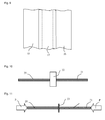
- the inventive method is also suitable for the preparation of a dilation element, which in the Fig. 8 has in section and 9 shown in plan basic structure.
- the dilation element comprises two spaced-apart metal strips 15 and 16 joined by a single rubber strip 17 or two rubber strips 17 and 18.
- the metal strips 15 and 16 and the rubber strips 17 and 18 are glued together by means of adhesive films 19.
- the adhesive sheets 19 may be present only where the rubber strips 17 and 18 and the metal strips 15 and 16 overlap, or at least one of them may have the same width as the rubber strips 17 and 18 to achieve that the two rubber strips 17 and 18 are glued together.
- the process may be carried out, for example, with a conventional rotary vulcanization equipment (also known as a rotary vulcanization press).
- a conventional rotary vulcanization equipment also known as a rotary vulcanization press.
- the system is used to remove the metal strips and rubber strips by activating the adhesive film under pressure and pressure permanently bonded to increased temperature.
- a vulcanization of the rubber strip is no longer because the rubber strips are already supplied as organized rubber strips.
- Such a system is also suitable for producing, instead of individual dilatation elements, an arbitrarily long dilatation element, ie a dilation band.
- the described methods are also suitable for joining together two parts (made of vulcanized rubber and / or of metal) in the form of a miter, which leads to a larger joining surface.
- the method according to the invention is furthermore suitable for forming a sealing ring directly on site from a rubber strip.
- a sealing ring directly on site from a rubber strip.
- the process step C of compression and cooling in this case advantageously takes place in a negative mold into which at least the end regions of the rubber strip formed into a ring can be inserted.
- the 10 and 11 illustrate the method according to the invention for the connection of two vulcanized rubber strips 20 and 21.
- the ends or end faces of the rubber strips 20 and 21 to be joined are heated, for example by means of a heating mirror 22 (FIG. Fig. 10 ), and then pressed together with an intermediate sheet 23 under a mutual pressure P (see FIG. 11 ).
- the rubber strips 20 and 21 may be inserted into a negative mold in order to be able to guide them correctly in compression, so that the end faces come to lie exactly against each other. If necessary, excesses of the film 23 are subsequently removed.
- a single rubber strip can be processed in the same way to a sealing ring.
- the adhesive films 3 used have the advantage that they are not sticky and unfold their adhesiveness only after heating above a predetermined temperature.
Abstract
Ein Verfahren zur Herstellung eines Verbunds aus mindestens zwei Teilen (1, 4), von denen ein erstes Teil (1) aus einem Gummiwerkstoff und ein zweites Teil (4) aus einem Gummiwerkstoff oder aus Metall besteht, wobei eine erste Fläche des ersten Teils (1) mit einer zweiten Fläche des zweiten Teils (4) verbunden wird, umfasst die Schritte:
A) Bereitstellen des ersten Teils aus dem Gummiwerkstoff als vulkanisiertes Gummiteil,
B) Bereitstellen des zweiten Teils aus dem Gummiwerkstoff als vulkanisiertes Gummiteil, sofern das zweite Teil aus einem Gummiwerkstoff besteht, oder Reinigen der zweiten Fläche, um Fettspuren und eine allfällige Oxidschicht zu entfernen, sofern das zweite Teil aus Metall besteht,
C) Bilden eines dauerhaften Verbunds aus dem ersten Teil (1) und dem zweiten Teil (4) durch Verkleben der beiden Teile mittels einer Klebefolie (3).
Description
- Die Erfindung betrifft ein Verfahren zum Verbinden von Teilen oder Flächen aus einem Gummiwerkstoff und/oder Metall.
- Die Verbindung eines Teils aus Metall und eines Teils aus Gummi erfolgt heutzutage mittels eines Verfahrens, das im wesentlichen die folgenden Schritte umfasst:
- Reinigen des Metalls, um Fettspuren und Oxidschichten zu entfernen. Dies erfolgt in der Regel durch Sandstrahlen.
- Auftragen einer Primerschicht auf das Metall.
- Auftragen einer Haftschicht auf die Primerschicht.
- Platzieren des Gummiteils auf dem Metallteil, wobei sich nun die Primerschicht und die Haftschicht zwischen den beiden Teilen befinden.
- Erwärmen des Verbunds, um das Gummiteil zu vulkanisieren.
- Der letzte Schritt muss innerhalb einer Form erfolgen, da der Gummi sonst beim Vulkanisieren auseinanderläuft. Es sind zudem zwei Schichten, nämlich die Primerschicht und die Haftschicht erforderlich, um die dauerhafte Verbindung zwischen den beiden Teilen zu erreichen.
- Zum Verbinden von Gummistreifen zu einem Gummidichtungsring ist es bekannt aus
DE-C-198 20 293 , auf den beiden Stirnenden eines länglichen Gummistreifens ein Vulkanisationsmittel aufzutragen, um den Gummistreifen so zu einem geschlossenen Ring zu formen, wobei die Nahtstelle zwischen den Stirnenden beheizt und ausvulkanisiert wird. Dabei werden die beiden Stirnenden während des Heizvorgangs gegeneinandergepresst. Die zugehörige Vorrichtung weist zwei beheizbare, einander zustellbare Pressbacken auf. In den Pressbacken sind Ausnehmungen zur Aufnahme des Dichtungsringes vorgesehen, die an die Kontur des Dichtungsringes angepasst sind. Eine der beiden Pressbacken ist aus drei hintereinander angeordneten Teilen ausgebildet, wobei die beiden äusseren Teile aufeinander zustellbar sind. Die Ausnehmungen der beiden äusseren Teile sind dichter anliegend an der Kontur des Gummistreifens ausgebildet als die Ausnehmung des mittleren Teils. - Die Verbindung von Gummistreifen mit einem Vulkanisationsmittel und einem lokalen Vulkanisationsvorgang braucht einen hohen apparativen Aufwand und kann somit nur in einer industriellen Umgebung vorgenommen werden.
- Wenn das obige Verfahren an grösseren Gummiteilen, z.B. dickere Gummischeiben oder dergleichen, angewendet werden soll, ist der apparative Aufwand noch grösser.
- Der vorliegenden Erfindung liegt die Aufgabe zugrunde, ein Verbindungsverfahren für Teile aus einem Gummiwerkstoff und/oder aus Metall anzugeben, welches einfach ist und bei gewissen Anwendungen direkt vor Ort durchgeführt werden kann. Dabei sollen Teile von kleiner bis grosser Dicke zusammengefügt werden können.
- Diese Aufgabe wird durch ein Verbindungsverfahren mit den Merkmalen des Patentanspruchs 1 gelöst. Ausgangspunkt des Verbindungsverfahrens sind vulkanisierte Gummiteile, die mittels Klebefolien miteinander und/oder oder mit Teilen aus Metall zu einem Verbund verbunden werden, wobei die Klebefolien durch Erwärmung zum Schmelzen gebracht und dadurch aktiviert werden, so dass eine dauerhafte Verbindung entsteht. Die abhängigen Ansprüche betreffen vorteilhafte Varianten und Arbeitsbereiche, insbesondere vorteilhafte Arbeitsbereiche von Druck und Temperatur.
- Als Klebefolien eignen sich beispielsweise thermoplastische Folien, insbesondere thermoplastische Folien aus einem Polyolefin wie beispielsweise Polypropylen oder Polyethylen, oder Folien aus einem Copolymer. Die Klebefolien zeichnen sich dadurch aus, dass sie ihre Klebefähigkeit erst bei Erwärmung über ihren Schmelzpunkt entfalten, die nach dem Abkühlen erhalten bleibt.
- Das erfindungsgemässe Verbindungsverfahren hat den grossen Vorteil, dass sowohl grössere Gummiteile wie beispielsweise dicke Gummischeiben als auch kleinere Gummiteile wie beispielsweise Gummistreifen auf einfache Art und ohne grossen apparativen Aufwand an einem beliebigen Ort miteinander oder mit einem Teil aus Metall verbunden werden können, beispielsweise um einen Dichtungsring oder ein Drucklager zu erhalten. Bei der Verbindung von Gummiteile und Metallteilen ergibt sich der Vorteil, dass das kostspielige Auftragen von Primerschicht und Haftschicht entfällt.
- Die Erfindung wird nun anhand von Ausführungsbeispielen und der Zeichnung näher erläutert. Die Figuren sind schematisch und nicht massstäblich gezeichnet. Es zeigen:
- Fig. 1 - 4
- Schritte eines Verfahrens zum Verbinden von zwei Teilen aus einem Gummiwerkstoff und/oder Metall,
- Fig. 5
- einen nach dem Verfahren hergestellten Verbund mit drei dicken Gummischeiben,
- Fig. 6
- einen nach dem Verfahren hergestellten Verbund mit zwei aussen- liegenden Metallplatten und einer inneren Gummischeibe,
- Fig. 7
- einen nach dem Verfahren hergestellten Verbund mit drei Metallplat- ten und zwei Gummischeiben,
- Fig. 8, 9
- Schritte eines Verfahrens zum Herstellen eines Dilatationselementes, und
- Fig. 10, 11
- Schritte eines Verfahrens zum Verbinden der Stirnseiten von zwei einander gegenüberliegenden Gummistreifen.
- Die Erfindung wird im folgenden im Detail erläutert anhand verschiedener Beispiele, nämlich
- 1) eines Verfahrens zur Herstellung eines Drucklagers, das aus mehreren Gummiteilen besteht,
- 2) eines Verfahrens zur Herstellung eines Drucklagers oder eines Fassadenelementes, das aus Gummiteilen und Metallteilen besteht,
- 3) eines Verfahrens zur Herstellung eines Dilatationselementes, und
- 4) eines Verfahrens zur Herstellung eines Dichtungsringes aus Gummi.
- Dieses Verfahren wird nun im Detail erläutert für ein Drucklager, bei dem zwei Teile 1 und 4 aus einem Gummiwerkstoff miteinander zu einem Verbund verbunden werden, und zwar anhand von zwei Varianten. Die beiden Teile sind beispielsweise scheibenförmig oder plattenförmig mit einem beliebigen Umriss. Ein solches Drucklager wird beispielsweise bei Strassenbrücken eingesetzt. Das Verfahren umfasst gemäss Variante 1 die folgenden Schritte A bis D:
- A) Bereitstellen der beiden Teile 1 und 4 als vulkanisierte Gummiteile.
Ausgangspunkt des Verfahrens sind vulkanisierte Gummiteile, deren wesentliche Eigenschaft darin besteht, dass sie ihre Form und Grösse bei den nachfolgenden Schritten nicht mehr ändern. Drucklager unterschiedlicher Grösse lassen sich auf einfache Weise herstellen, indem beispielsweise eine grosse Platte aus Gummi vulkanisiert wird und dann Scheiben oder Platten entsprechend dem Umriss und der Abmessung des Drucklagers aus der vulkanisierten Platte ausgestanzt werden. Diese vulkanisierten Gummischeiben und Gummiplatten sind Beispiele für die Form der Teile 1 und 4. - B) Bilden eines Verbunds aus dem ersten Teil 1 und dem zweiten Teil 4 und einer Klebefolie 3, wobei sich die Klebefolie 3 zwischen den Teilen 1 und 4 befindet,
- C) Zusammenpressen und Erwärmen des Verbunds auf eine Temperatur, die höher ist als eine vorbestimmte Mindesttemperatur, so dass die Klebefolie 3 schmilzt,
- D) Abkühlen des Verbunds.
- Auf welche Art und Weise die Verfahrensschritte B und C im einzelnen durchgeführt werden, hängt davon ab, ob das Drucklager als Einzelanfertigung oder in kleiner Stückzahl und/oder lokal vor Ort, zum Beispiel auf einer Baustelle, oder ob es in grösserer Stückzahl in einer industriellen Umgebung hergestellt wird.
- Die
Fig. 1 bis 4 illustrieren ein Verfahren gemäss Variante 2, das sich sehr gut für kleine Stückzahlen eignet. Bei diesem Verfahren erfolgen die Tätigkeiten der Verfahrensschritte B und C in leicht modifizierter Form und Reihenfolge, nämlich durch die Schritte - C1) Erwärmen der Teile 1 und 4 oder zumindest der miteinander zu verklebenden Flächen der Teile 1 und 4 auf eine Temperatur, die höher ist als die vorbestimmte Mindesttemperatur,
- B) Bilden eines Verbunds aus dem ersten Teil 1 und dem zweiten Teil 4 und einer Klebefolie 3, wobei die Klebefolie 3 schmilzt, sobald sie in Kontakt mit dem über ihre Schmelztemperatur erwärmten Teil 1 und/oder Teil 4 kommt,
- C2) Zusammenpressen des Verbunds.
- Im wesentlichen wird also der Verfahrensschritt C in zwei Teilschritte C1 und C2 aufgeteilt und der Teilschritt C1 vor dem Verfahrensschritt B durchgeführt.
- Das Erwärmen der Teile 1 und 4 im Verfahrenschritt C1 kann mittels unterschiedlicher, bevorzugt mobiler, Wärmequellen erfolgen, beispielsweise mittels eines Ofens, eines Heizspiegels, eines Infrarotstrahlers, eines Heissluftföhns, etc. Die
Fig. 1 zeigt die Erwärmung des ersten Teils 1, das im vorliegenden Fall eine dicke Gummischeibe ist, durch einen oberhalb des ersten Teils 1 angeordneten Heizspiegel 2. In der Regel berührt der Heizspiegel 2 die Gummischeibe und erwärmt sie durch direkte Wärmeübertragung. Die Temperatur kann beispielsweise mit einem Strahlungsthermometer (Pyrometer) gemessen werden. Die Mindesttemperatur hängt von der Klebefolie 3 ab. Sie liegt in der Regel um 20 bis 100°C höher als die Schmelztemperatur der Klebefolie 3. In der Praxis erhaltene Werte sind: - 100 bis 130°C, typischerweise 110°C für die Schmelztemperatur, und
- 150 bis 200°C für die zu erreichende Mindesttemperatur.
- Die
Fig. 2 zeigt den Zustand, nachdem die Klebefolie 3 auf eine Oberfläche des ersten Teils 1 aufgebracht wurde. - Die
Fig. 3 zeigt, wie das zweite Teil 4, im vorliegenden Fall ebenfalls eine dicke Gummischeibe, mittels eines Heizspiegels 5 erwärmt wird, ebenfalls auf eine vorbestimmte Mindesttemperatur, die bevorzugt ebenfalls im Bereich zwischen 150 und 200°C liegt. Der Heizspiegel 5 ist in derFig. 3 als unterhalb des Teils 4 liegend dargestellt, um zu illustrieren, dass es beim Erwärmen der Teile 1 und 4 vor allem darum geht, die miteinander zu verbindenden Oberflächen zu erwärmen. - Das Erwärmen der Teile 1 und 4 und das Aufbringen der Klebefolie 3 werden mit Vorteil soweit als möglich parallel durchgeführt. Die Teile 1 und 4 werden dann zu einem Verbund zusammengefügt, so dass sich die Klebefolie 3 zwischen den beiden Teilen 1 und 4 befindet. Die Klebefolie 3 schmilzt, sobald sie in Kontakt mit dem Teil 1 und/oder dem Teil 4 kommt.
- Die
Fig. 4 illustriert schematisch den Verfahrenschritt C2. Der Verbund wird in einer Presse mit zwei Pressbacken P zusammengepresst. Der Pressdruck liegt typischerweise in einem Bereich von 800 bis 3000 Gramm/cm2. Der Pressdruck wird für eine gewisse Dauer aufrechterhalten, um sicherzustellen, dass die Verbindung zwischen den Teilen 1 und 4 nach dem Abkühlen dauerhaft ist. - Der Pressdruck wird während des Abkühlens aufrechterhalten, bis sich der Verbund auf eine unterhalb der Schmelztemperatur der Klebefolie 3 liegende Temperatur, typischerweise auf eine Temperatur von 60 bis 80°C, vorzugsweise etwa 70 °C, abgekühlt hat.
- Ein nach diesem Verfahren hergestellter Verbund ist nun seinerseits ein Teil aus einem Gummiwerkstoff und kann mit weiteren Teilen aus einem Gummiwerkstoff oder aus Metall verbunden werden. Das erfindungsgemässe Verfahren kann nämlich auch zum Verbinden eines ersten Teils aus einem Gummiwerkstoff und eines zweiten Teils, das aus Metall besteht, verwendet werden. In diesem Fall eignet sich als Klebefolie 3 insbesondere eine Folie aus einem Copolymer.
- Die
Fig. 5 zeigt einen Verbund aus drei dicken Gummischeiben 1, 4 und 7, welche mittels dünner Klebefolie 3 und 6 miteinander verklebt worden sind. Ein solches Drucklager, das aus mehr als zwei Teilen 1 und 4 gebildet ist, kann bis zu einer gewissen Anzahl von Teilen gemäss der Variante 1 oder der Variante 2 hergestellt werden. Bei einem Drucklager mit drei Gummischeiben kann z.B. das Verfahren gemäss Variante 2 zweimal durchgeführt werden, zuerst um die beiden Gummischeiben 1 und 4 miteinander zu verbinden, und dann noch einmal um den so entstandenen Verbund mit der Gummischeibe 7 zu verbinden. Das Drucklager kann aber auch gemäss Variante 1 hergestellt werden, in dem im Verfahrensschritt B der Verbund in der in derFig. 5 dargestellten Reihenfolge gebildet wird. Zu bemerken ist noch, dass die Klebefolie 3 in diesen Schnittzeichnungen ohne Vergrösserung nicht mehr sichtbar wäre. - Es ist möglich, auf die gleiche Art und Weise mittels einer weiteren Klebefolie ein Vlies oder dergleichen auf der Bodenfläche bzw. Deckfläche des Verbunds zu befestigen.
- Die
Fig. 6 zeigt einen Verbund, der aus zwei Metallplatten 8 und 9 und einem Gummiteil in Form einer Gummischeibe 4 besteht, welche mittels Klebefolien 3 und 6 miteinander verklebt worden sind. Die Metallplatten 8 und 9 bestehen beispielsweise aus rostfreiem Stahl. Ein solcher Verbund kann Verwendung finden als Drucklager oder als Fassadenelement, wobei dann natürlich die verwendeten Metalle und die Abmessungen des Verbunds entsprechend seinem Zweck anzupassen sind. Das erfindungsgemässe Verfahren ermöglicht die Herstellung von grossflächigen Fassadenelementen, die eine ausreichende Stabilität aufweisen und dem Architekten viele Gestaltungsmöglichkeiten bieten. Ein solches Fassadenelement besteht aus zwei Metallblechen und einem Gummiteil, die miteinander mittels Klebefolien verklebt sind, und hat den Aufbau des in derFig. 6 dargestellten Verbunds. Die Metallplatten 8 und 9 sind grossflächige Bleche von typischerweise mehreren Quadratmetern und können aus den verschiedensten Metallen und Metalllegierungen bestehen. - Falls ein Drucklager mit einer noch grösseren Dicke benötigt wird, können weitere Gummischeiben und Metallplatten in abwechselnder Reihenfolge hinzu verbunden werden. Die
Fig. 7 zeigt als Beispiel einen Verbund mit drei Metallplatten 8, 9 und 13 und dazwischenliegenden Gummischeiben 4 und 11, die mittels Klebefolien 6, 3, 10 und 12 dauerhaft verklebt wurden. - Diese Verbunde können im Prinzip mit den gleichen, oben beschriebenen Verfahren wie die Drucklager ohne Metallteile hergestellt werden, wobei jedoch die zu verklebenden Flächen der Metallteile vor dem Verfahrensschritt B, in dem der Verbund gebildet wird, gereinigt werden müssen, um allfällige Fettspuren wie auch eine allfällige Oxidationsschicht zu entfernen. Diese Reinigung erfolgt beispielsweise durch Sandstrahlen, das den Vorteil hat, dass die Metallfläche zugleich aufgeraut wird, was die Haftfähigkeit verbessert. Das Verfahren umfasst gemäss einer ersten Variante die Schritte:
- A1) Bereitstellen der Gummiteile als vulkanisierte Gummiteile.
- A2) Reinigen der zu verklebenden Flächen der Metallteile.
- B) Bilden eines Verbunds aus den zu verklebenden Teilen und Klebefolien,
- C) Zusammenpressen und Erwärmen des Verbunds auf eine Temperatur, die höher ist als eine vorbestimmte Mindesttemperatur, so dass die Klebefolien schmelzen, und
- D) Abkühlen des Verbunds auf eine tiefere Temperatur.
- Das Verfahren umfasst gemäss einer zweiten Variante die Schritte:
- A1) Bereitstellen der Gummiteile als vulkanisierte Gummiteile.
- A2) Reinigen der zu verklebenden Flächen der Metallteile.
- C1) Erwärmen der zu verklebenden Flächen auf eine Temperatur, die höher ist als eine vorbestimmte Mindesttemperatur,
- B) Bilden eines Verbunds aus den zu verklebenden Teilen und Klebefolien, C2) Zusammenpressen des Verbunds, und
- D) Abkühlen des Verbunds.
- Das erfindungsgemässe Verfahren eignet sich auch zur Herstellung eines Dilatationselementes, das die in den
Fig. 8 im Schnitt und 9 in Aufsicht dargestellte Grundstruktur aufweist. Das Dilatationselement umfasst zwei im Abstand zueinander verlaufende Metallstreifen 15 und 16, die durch einen einzigen Gummistreifen 17 oder zwei Gummistreifen 17 und 18 miteinander verbunden sind. Die Metallstreifen 15 und 16 und die Gummistreifen 17 und 18 sind mittels Klebefolien 19 miteinander verklebt. Die Klebefolien 19 können wie dargestellt nur dort vorhanden sein, wo die Gummistreifen 17 und 18 und die Metallstreifen 15 und 16 überlappen, oder wenigstens eine davon kann die gleiche Breite wie die Gummistreifen 17 und 18 aufweisen, um zu erreichen, dass auch die beiden Gummistreifen 17 und 18 miteinander verklebt werden. - Das Verfahren umfasst die Schritte:
- A1) Bereitstellen der Gummistreifen als vulkanisierte Gummistreifen.
- A2) Reinigen der zu verklebenden Flächen der Metallstreifen.
- B) Bilden des Dilatationselementes als Verbund aus den zu verklebenden Teilen und Klebefolien,
- C) Zusammenpressen und Erwärmen des Verbunds auf eine Temperatur, die höher ist als eine vorbestimmte Mindesttemperatur, so dass die Klebefolien schmelzen, und
- D) Abkühlen des Verbunds auf eine tiefere Temperatur.
- Das Verfahren kann beispielsweise mit einer herkömmlichen Rotations-Vulkanisationsanlage (auch als Rotations-Vulkanisationspresse bekannt) durchgeführt werden. Die Anlage wird dabei benutzt, um die Metallstreifen und Gummistreifen durch Aktivierung der Klebefolie unter Anwendung von Druck und erhöhter Temperatur dauerhaft zu verkleben. Eine Vulkanisation der Gummistreifen erfolgt jedoch nicht mehr, da die Gummistreifen bereits als organisierte Gummistreifen zugeführt werden. Eine solche Anlage eignet sich auch, um anstelle von einzelnen Dilatationselementen ein beliebig langes Dilatationselement, d.h. ein Dilatationsband herzustellen.
- Die beschriebenen Verfahren eignen sich auch, um zwei Teile (aus vulkanisiertem Gummi und/oder aus Metall) in Form einer Gehrung miteinander zu verbinden, was zu einer grösseren Verbindungsfläche führt.
- Das erfindungsgemässe Verfahren eignet sich des weiteren, um direkt vor Ort aus einem Gummistreifen einen Dichtungsring zu bilden. Dabei müssen nur die Endbereiche des Gummistreifens erwärmt werden. Der Verfahrenschritt C des Zusammenpressens und die Abkühlung erfolgt in diesem Fall jedoch mit Vorteil in einer Negativform, in welche zumindest die Endbereiche des zu einem Ring geformten Gummistreifens hineingelegt werden können. Des weiteren ist es natürlich möglich, die Enden des Gummistreifens zu gehren, um eine grössere Verbindungsfläche zu erhalten.
- Die
Fig. 10 und 11 illustrieren das erfindungsgemässe Verfahren für die Verbindung von zwei vulkanisierten Gummistreifen 20 und 21. Die zu verbindenden Enden bzw. Stirnseiten der Gummistreifen 20 und 21 werden erwärmt, beispielsweise mittels eines Heizspiegels 22 (Fig. 10 ), und dann mit einer dazwischenliegenden Folie 23 unter einem gegenseitigen Druck P zusammengepresst (sieheFigur 11 ). Die Gummistreifen 20 und 21 können dazu in eine Negativform eingelegt sein, um sie bem Zusammenpressen richtig führen zu können, so dass die Stirnseiten genau aneinander zu liegen kommen. Überschüsse der Folie 23 werden bei Bedarf anschliessend entfernt. Ein einziger Gummistreifen kann auf die gleiche Art und Weise zu einem Dichtungsring verarbeitet werden. - Die verwendeten Klebefolien 3 haben den Vorteil, dass sie nicht klebrig sind und ihre Klebefähigkeit erst nach Erwärmung über eine vorbestimmte Temperatur entfalten.
Claims (12)
- Verfahren zur Herstellung eines Verbunds aus mindestens zwei Teilen, von denen ein erstes Teil aus einem Gummiwerkstoff und ein zweites Teil aus einem Gummiwerkstoff oder aus Metall besteht, wobei eine erste Fläche des ersten Teils mit einer zweiten Fläche des zweiten Teils verbunden wird, umfassend die Schritte:A) Bereitstellen des ersten Teils aus dem Gummiwerkstoff als vulkanisiertes Gummiteil,B) Bereitstellen des zweiten Teils aus dem Gummiwerkstoff als vulkanisiertes Gummiteil, sofern das zweite Teil aus einem Gummiwerkstoff besteht, oder
Reinigen der zweiten Fläche, um Fettspuren und eine allfällige Oxidschicht zu entfernen, sofern das zweite Teil aus Metall besteht,C) Bilden eines dauerhaften Verbunds aus dem ersten Teil (1) und dem zweiten Teil (4) durch Verkleben der beiden Teile mittels einer Klebefolie (3). - Verfahren nach Anspruch 1, dadurch gekennzeichnet, dass der Schritt C die folgenden Schritte umfasst:C1) Erwärmen der Teile (1) und (4) oder zumindest der miteinander zu verklebenden Flächen der Teile (1) und (4) auf eine Temperatur, die höher ist als eine vorbestimmte Mindesttemperatur,C2) Bilden eines Verbunds aus dem ersten Teil (1) und dem zweiten Teil (4) und der Klebefolie (3), wobei sich die Klebefolie (3) zwischen den Teilen (1) und (4) befindet,C3) Zusammenpressen des Verbunds, undC4) Abkühlen des Verbunds.
- Verfahren nach Anspruch 1, dadurch gekennzeichnet, dass der Schritt C die folgenden Schritte umfasst:C1) Bilden eines Verbunds aus dem ersten Teil (1) und dem zweiten Teil (4) und der Klebefolie (3), wobei sich die Klebefolie (3) zwischen den Teilen (1) und (4) befindet,C1) Zusammenpressen des Verbunds und Erwärmen des Verbunds oder zumindest der miteinander zu verklebenden Flächen auf eine Temperatur, die höher ist als eine vorbestimmte Mindesttemperatur,C3) Warten, bis die Klebefolie (3) schmilzt, undC4) Abkühlen des Verbunds.
- Verfahren nach Anspruch 3, dadurch gekennzeichnet, dass das Zusammenpressen in einer Negativform erfolgt.
- Verfahren nach einem der Ansprüche 1 bis 4, dadurch gekennzeichnet, dass die Teile (1, 4) auf eine Temperatur erwärmt werden, die höher ist als eine Schmelztemperatur der Klebefolie (3).
- Verfahren nach einem der Ansprüche 1 bis 5, dadurch gekennzeichnet, dass das Abkühlen des Verbunds bis auf eine Temperatur im Bereich von 60 bis 80°C noch während des Zusammenpressens erfolgt.
- Verfahren nach einem der Ansprüche 1 bis 6, dadurch gekennzeichnet, dass die Teile bzw. Flächen (1, 4) mit einem Anpressdruck von 800 bis 3000 Gramm/cm2 gegeneinander gepresst werden.
- Verfahren nach einem der Ansprüche 1 bis 6, dadurch gekennzeichnet, dass die Teile (1, 4) ein einziger Gummistreifen mit zwei miteinander zu verklebenden Flächen sind.
- Drucklager mit mehreren Scheiben aus einem Gummiwerkstoff, hergestellt nach einem Verfahren nach einem der Ansprüche 1 bis 7.
- Drucklager mit mindestens einer Scheibe aus einem Gummiwerkstoff und mindestens zwei Metallplatten, hergestellt nach einem Verfahren nach einem der Anspruche 1 bis 7.
- Dilatationselement mit zwei Metallstreifen (15,16) und mindestens einem Gummistreifen (17,18), hergestellt nach einem Verfahren nach einem der Anspruche 1 bis 7.
- Fassadenelement mit zwei Metallblechen und einem dazwischen liegenden Gummiteil, hergestellt nach einem Verfahren nach einem der Anspruche 1 bis 7.
Applications Claiming Priority (1)
| Application Number | Priority Date | Filing Date | Title |
|---|---|---|---|
| CH01096/09A CH701469A2 (de) | 2009-07-14 | 2009-07-14 | Verfahren zum Verbinden von Teilen aus einem Gummiwerkstoff. |
Publications (1)
| Publication Number | Publication Date |
|---|---|
| EP2277685A1 true EP2277685A1 (de) | 2011-01-26 |
Family
ID=42610055
Family Applications (1)
| Application Number | Title | Priority Date | Filing Date |
|---|---|---|---|
| EP20100168496 Withdrawn EP2277685A1 (de) | 2009-07-14 | 2010-07-06 | Verfahren zum Verbinden von Teilen aus einem vulkanisierten Gummiwerkstoff und/oder aus Metall mittels einer Klebefolie |
Country Status (2)
| Country | Link |
|---|---|
| EP (1) | EP2277685A1 (de) |
| CH (1) | CH701469A2 (de) |
Cited By (1)
| Publication number | Priority date | Publication date | Assignee | Title |
|---|---|---|---|---|
| CN107553916A (zh) * | 2017-09-19 | 2018-01-09 | 合肥通泰光电科技有限公司 | 一种内嵌层式的推入显示屏胶框及其内胶框压合方法 |
Citations (10)
| Publication number | Priority date | Publication date | Assignee | Title |
|---|---|---|---|---|
| DE1231739B (de) * | 1963-01-12 | 1967-01-05 | Continental Gummi Werke Ag | Elastisch nachgiebiges Lager fuer Bruecken und aehnliche Bauwerke |
| FR2444551A1 (fr) * | 1978-12-22 | 1980-07-18 | Pont A Mousson | Procede de fabrication d'un element de tuyauterie comprenant un emboitement metallique et une garniture d'etancheite en caoutchouc |
| WO1997006205A2 (en) * | 1995-08-04 | 1997-02-20 | Uponor B.V. | Joining of polyolefin articles |
| JPH11333936A (ja) * | 1998-05-25 | 1999-12-07 | Toyo Tire & Rubber Co Ltd | 加硫ゴムシートの接合方法 |
| DE19820293C1 (de) | 1998-05-07 | 1999-12-30 | Cordes Theodor Gmbh & Co Kg | Vorrichtung zur Herstellung von Gummidichtungsringen |
| DE10146602C1 (de) * | 2001-09-21 | 2002-12-12 | Deflex Dichtsysteme Gmbh | Verfahren zur Herstellung von Rahmen für Fenster oder Türen |
| US20030033767A1 (en) * | 2001-08-03 | 2003-02-20 | Steve Mead | Raised access floor panel |
| US20060213605A1 (en) * | 2004-03-09 | 2006-09-28 | Takashi Kakubo | Method for adhesive-bonding vulcanized rubber compositions by the use of thermoplastic elastomer compositions |
| JP2006306096A (ja) * | 2000-11-10 | 2006-11-09 | Yokohama Rubber Co Ltd:The | ゴム積層体の製造方法 |
| EP2071091A2 (de) * | 2007-12-14 | 2009-06-17 | Schoop + Co. AG | Dehnfugenband |
-
2009
- 2009-07-14 CH CH01096/09A patent/CH701469A2/de unknown
-
2010
- 2010-07-06 EP EP20100168496 patent/EP2277685A1/de not_active Withdrawn
Patent Citations (10)
| Publication number | Priority date | Publication date | Assignee | Title |
|---|---|---|---|---|
| DE1231739B (de) * | 1963-01-12 | 1967-01-05 | Continental Gummi Werke Ag | Elastisch nachgiebiges Lager fuer Bruecken und aehnliche Bauwerke |
| FR2444551A1 (fr) * | 1978-12-22 | 1980-07-18 | Pont A Mousson | Procede de fabrication d'un element de tuyauterie comprenant un emboitement metallique et une garniture d'etancheite en caoutchouc |
| WO1997006205A2 (en) * | 1995-08-04 | 1997-02-20 | Uponor B.V. | Joining of polyolefin articles |
| DE19820293C1 (de) | 1998-05-07 | 1999-12-30 | Cordes Theodor Gmbh & Co Kg | Vorrichtung zur Herstellung von Gummidichtungsringen |
| JPH11333936A (ja) * | 1998-05-25 | 1999-12-07 | Toyo Tire & Rubber Co Ltd | 加硫ゴムシートの接合方法 |
| JP2006306096A (ja) * | 2000-11-10 | 2006-11-09 | Yokohama Rubber Co Ltd:The | ゴム積層体の製造方法 |
| US20030033767A1 (en) * | 2001-08-03 | 2003-02-20 | Steve Mead | Raised access floor panel |
| DE10146602C1 (de) * | 2001-09-21 | 2002-12-12 | Deflex Dichtsysteme Gmbh | Verfahren zur Herstellung von Rahmen für Fenster oder Türen |
| US20060213605A1 (en) * | 2004-03-09 | 2006-09-28 | Takashi Kakubo | Method for adhesive-bonding vulcanized rubber compositions by the use of thermoplastic elastomer compositions |
| EP2071091A2 (de) * | 2007-12-14 | 2009-06-17 | Schoop + Co. AG | Dehnfugenband |
Cited By (2)
| Publication number | Priority date | Publication date | Assignee | Title |
|---|---|---|---|---|
| CN107553916A (zh) * | 2017-09-19 | 2018-01-09 | 合肥通泰光电科技有限公司 | 一种内嵌层式的推入显示屏胶框及其内胶框压合方法 |
| CN107553916B (zh) * | 2017-09-19 | 2024-01-05 | 合肥通泰光电科技有限公司 | 一种内嵌层式的推入显示屏胶框及其内胶框压合方法 |
Also Published As
| Publication number | Publication date |
|---|---|
| CH701469A2 (de) | 2011-01-14 |
Similar Documents
| Publication | Publication Date | Title |
|---|---|---|
| EP3105038B1 (de) | Verfahren zur herstellung eines verbundbauteils | |
| DE202008017865U1 (de) | Profilwandungsstreifen zur Herstellung eines Abstandhalterrohres, Abstandhalterrohr für eine Isolierverglasung, sowie Vorrichtung zur Herstellung des Abstandhalterrohres | |
| DE60319467T2 (de) | Perforiete Klebefolie und Herstellungsverfahren | |
| EP3106300A1 (de) | Mehrschichtverbund, verfahren zu seiner herstellung und seine verwendung | |
| DE102012110658A1 (de) | Verfahren und Vorrichtung zur Verbindung von Dichtungsprofilen | |
| EP2277685A1 (de) | Verfahren zum Verbinden von Teilen aus einem vulkanisierten Gummiwerkstoff und/oder aus Metall mittels einer Klebefolie | |
| WO2017186817A1 (de) | Gerüstband mit verstärkungsmittel | |
| DE4021472C2 (de) | ||
| WO2014015954A1 (de) | Verfahren und vorrichtung zum verbinden zumindest zweier bestandteile einer brennstoffzelle | |
| EP1661660A1 (de) | Klinge und Verfahren zur Herstellung derselben | |
| AT519010B1 (de) | Kfz-Bauteil | |
| EP2083130B1 (de) | Verfahren zur Herstellung einer Höckerverbundplatte | |
| EP0392297B1 (de) | Verfahren zum Verbinden flächenhafter Gebilde mittels wärmeaktivierbarer Klebefolie | |
| DE3741692C2 (de) | Verfahren zur Herstellung eines Verbundteiles sowie Verbundteil | |
| DE2446869C2 (de) | Umhüllen eines Gegenstandes | |
| DE102018109488B4 (de) | Verfahren zum klebenden Fügen eines ersten und zweiten Fügepartners | |
| EP2275242B1 (de) | Verfahren zum Aufheizen und Umformen von Termoplast-Platinen mittels Wärmeleitung | |
| EP3170661B1 (de) | Niederdruck-dünnwandwärmetauscher und verfahren zur herstellung eines solchen | |
| DE102014118979A1 (de) | Verfahren zum Herstellen eines aufblasbaren, luftdichten Körpers mit mindestens einer Überlappungsnaht | |
| AT512204B1 (de) | Formteil und thermoformverfahren zur herstellung eines mehrere schichten aufweisenden formteils | |
| WO2006136264A1 (de) | Verfahren zum klebenden verbinden der stirnenden von hohlkammerprofilen und einrichtung zur durchführung des verfahrens | |
| DE102016118422A1 (de) | Verfahren zum Fügen eines ersten Bauteils und eines zweiten Bauteils | |
| DE1504742A1 (de) | Verfahren und Vorrichtung zum Verbinden von duennen Metallfolien mit Hartschaum | |
| DE102014217075A1 (de) | Verfahren zum Herstellen einer Temperiervorrichtung und Temperiervorrichtung | |
| EP3686003A1 (de) | Verbundleichtbauplatte und verfahren zu deren herstellung |
Legal Events
| Date | Code | Title | Description |
|---|---|---|---|
| PUAI | Public reference made under article 153(3) epc to a published international application that has entered the european phase |
Free format text: ORIGINAL CODE: 0009012 |
|
| AK | Designated contracting states |
Kind code of ref document: A1 Designated state(s): AL AT BE BG CH CY CZ DE DK EE ES FI FR GB GR HR HU IE IS IT LI LT LU LV MC MK MT NL NO PL PT RO SE SI SK SM TR |
|
| AX | Request for extension of the european patent |
Extension state: BA ME RS |
|
| STAA | Information on the status of an ep patent application or granted ep patent |
Free format text: STATUS: THE APPLICATION IS DEEMED TO BE WITHDRAWN |
|
| 18D | Application deemed to be withdrawn |
Effective date: 20110727 |