EP2277653B1 - Verfahren zur Bestimmung des Abstands zwischen einer autogenen Brennereinrichtung und einem Werkstück durch Erfassung einer Kerngrösse ohne eine eigene elektrische Energieversorgung - Google Patents
Verfahren zur Bestimmung des Abstands zwischen einer autogenen Brennereinrichtung und einem Werkstück durch Erfassung einer Kerngrösse ohne eine eigene elektrische Energieversorgung Download PDFInfo
- Publication number
- EP2277653B1 EP2277653B1 EP10007350.1A EP10007350A EP2277653B1 EP 2277653 B1 EP2277653 B1 EP 2277653B1 EP 10007350 A EP10007350 A EP 10007350A EP 2277653 B1 EP2277653 B1 EP 2277653B1
- Authority
- EP
- European Patent Office
- Prior art keywords
- distance
- workpiece
- burner
- burner means
- electrical
- Prior art date
- Legal status (The legal status is an assumption and is not a legal conclusion. Google has not performed a legal analysis and makes no representation as to the accuracy of the status listed.)
- Not-in-force
Links
Images


Classifications
-
- B—PERFORMING OPERATIONS; TRANSPORTING
- B23—MACHINE TOOLS; METAL-WORKING NOT OTHERWISE PROVIDED FOR
- B23K—SOLDERING OR UNSOLDERING; WELDING; CLADDING OR PLATING BY SOLDERING OR WELDING; CUTTING BY APPLYING HEAT LOCALLY, e.g. FLAME CUTTING; WORKING BY LASER BEAM
- B23K7/00—Cutting, scarfing, or desurfacing by applying flames
- B23K7/10—Auxiliary devices, e.g. for guiding or supporting the torch
- B23K7/102—Auxiliary devices, e.g. for guiding or supporting the torch for controlling the spatial relationship between the workpieces and the gas torch
Definitions
- the invention relates to a method for determining the distance between an autogenous burner device and a workpiece according to the preamble of claim 1 (see, for example, US Pat. DE 1 220 356 ). It can be used particularly advantageously for a regulation of this distance during the process of thermal separation.
- An autogenous burner device is used in the autogenous thermal separation and joining of materials.
- a welding torch is usually used as burner device in the context of autogenous welding.
- a comparable burner device can also be used for thermal separation, ie for flame cutting, of materials. Compared to other cutting methods this allows autogenous flame cutting involves the separation of very large and in particular very thick workpieces, for example metal sheets with thicknesses greater than 50 mm, with a higher cutting speed than other methods.
- DE 1962170 C is a method of controlling the feed of an automatic gas cutting device described, in which the potential occurring between the nozzle and the workpiece is to be used as a measured variable. It is said, however, that this electrical measurement is once independent of the gas composition and the distance of the nozzle to the workpiece, so that a distance measurement in this form is not possible.
- the US 2,364,645 relates to a technical solution that can be used in autogenous thermal separation.
- the nozzle of a burner is part of an electrical circuit with which a distance control of the nozzle to the workpiece is to be achieved.
- An electric current should flow actively through the burner flame between burner and workpiece.
- Active power requires an electric power source, in this case a battery.
- the electrical circuit is elaborate. The time constant to be taken into account in the control of the distance is therefore large and the accuracy is limited.
- the DE 27 24 909 A1 again, a method for automatically guiding a gas cutting torch to find the cutting edge. It should be detected for this purpose, the resistance of the cutting flame between the burner and the workpiece in a measuring circuit. The occurring due to the impact of the cutting flame on the workpiece edge resistance change is for the start signal to the beginning of the preheating with be used subsequent cutting phase. In this case, the large difference of the changing the impact of the cutting flame electrical resistance to be exploited.
- the electrical resistance changes from an initial value of several 100 kOhm down by 1 to 3 orders of magnitude down, which represents a significant difference that can be easily and safely exploited for this type of control.
- DD 282802 A7 and the DD 249 598 A1 relate to methods for controlling the burner distance and for process control during thermal separation. It should be at the DD 249 598 A3 known technique, performed at very high cost, an electrical alternating current with high frequency through the burner flame and thereby detects the positive and the negative half-wave below the saturation current in the gas plasma and stored. These values should be compared with default values and used for the control.
- DD 282 802 A7 periodically described a sequence of at least 11 temporally short, different in magnitude, positive constant direct currents are passed through the gas plasma. The voltage drops are stored and measured.
- the average increase of the linear part of the characteristic curve and the buckling current with limit values should be compared and linked to process control variables. Again, a lot of effort is required, although a large time constant must be accepted.
- the invention is based on the object to show ways to determine the distance between an autogenous burner device and a workpiece, which allow efficient distance determination with simple means and small time constant for a control of the distance.
- the invention is based on the recognition that the combustion gas mixture used for thermal processing in the autogenous engineering, in particular the burner flame, can be used for determining the distance between a burner device and a workpiece.
- This has the advantage that the distance measurement can be done relatively precisely, namely with respect to the position of the burner flame itself. In this way, measurement inaccuracies caused by a separate sensor device arranged at a distance from the burner flame can be avoided.
- a gas mixture of oxygen and acetylene (ethyne) is burned.
- acetylene acetylene
- this ionization can be taken into account and used to determine the distance be used.
- electrodes can be introduced into the burner flame and the change in an electrical current flow through the electrodes as a result of a change in the ionization when the distance between the burner device and the workpiece is detected. It has been found that the proportion, distribution and movement of the ions in the burner flame are related to the distance of the burner means from the workpiece.
- the detection of the ionization at least one of the burner flame inherent electrical characteristic can be detected as a characteristic distance variable f (d), which is also relatively easily accessible to electrical detection.
- the detected electrical signal can be further processed in an electronic evaluation device.
- the ionization of the atoms within the burner flame is detected by detecting an electrical parameter at the burner device and / or between the burner device and the workpiece.
- electrical signals are determined, which are directly accessible to further processing in an electrical evaluation device.
- an existing burner device can be used without major modifications, in particular without the installation of sensors.
- the electrical characteristic between the burner device and ground potential or a constant current or voltage source can be detected become.
- At least one electrical voltage between the burner device and the workpiece At least one electrical voltage between the burner device and the workpiece.
- a detection of the electrical parameter can be carried out passively without own electrical power supply and there is no electrical current flow over the burner flame actively performed with a suitable electrical power or voltage source. Only a measurement of the potential difference between the burner device and the workpiece or ground potential or a constant electrical voltage potential is required.
- the distance variable f (d) to be detected is in a characteristic relationship with the distance ds between the burner device and the workpiece.
- the relationship f (d) ⁇ -> ds can be of any type, it is crucial that an association between the distance ds and the distance variable f (d) can be made, for example via a table or material-specific calibration values.
- the characteristic relationship may be a relation or function in the mathematical sense.
- a distance ds is understood in the context of this application, the distance of the tip of the burner device to the workpiece. Depending on the definition, the distance ds can also be related to other parts of the burner device.
- the distance between burner device and workpiece is regulated as a function of the rise (dU / dt) or (dU) / ds of the electrical voltage as a function of time or as a function of the changing distance (ds) between burner device and workpiece (3).
- the procedure can be such that the distance between the burner device and the workpiece is cyclically changed so that it is regulated between the detectable electrical voltage maximum.
- the distance between the burner device and the workpiece can be changed during the regulation of the distance and the detection of the at least one local maximum and / or minimum of the electrical voltage can be carried out cyclically.
- the movement can be carried out translationally between two reversal points. This measurement can be performed several times per second, so that a detection can be performed almost constantly.
- the distance is redetermined in each of these measurements and can be used for a permanent control of the distance.
- local surface changes soiling, color, rust or surface geometry changes
- connection of the cutting oxygen by means of at least one detected electrical parameter after performing a preheating before the start of autogenous cutting.
- a distance control between the burner device and the workpiece takes place depending on the distance variable.
- an undesired change in the distance can be compensated automatically by surface irregularities of the workpiece.
- the burner flame can always be kept in the range of its best effectiveness, namely the highest temperature with respect to the workpiece.
- possible collisions of the workpiece with the burner device or with distance sensors, as they are known from the prior art avoided.
- higher precision in cutting and joining workpieces is possible.
- higher feed rates and thus cutting or joining speeds can be realized.
- a flow measurement is carried out for determining the flow rate of the gas flowing through at least one of the gas supply lines of the burner device.
- An autogenous burner device is usually supplied with two gases, namely oxygen and acetylene. Oxygen and acetylene are mixed in the burner device on the one hand to a heating gas.
- oxygen is taken out of the burner device from a separate nozzle as cutting oxygen.
- a flow measurement of the oxygen and / or acetylene flowing into the burner device is helpful for an automatic flame or cutting control. In particular, the size of the flame can be adjusted automatically.
- the distance control between the burner device and the workpiece additionally takes place as a function of the ascertained flow rate of at least one gas.
- the distance control can automatically consider the respective size of the flame and make a distance adjustment to the best working point.
- a material temperature determination in the region that is influenced by the burner flame can be carried out, and the detected temperature can be taken into account in the regulation of the distance between the burner device and the workpiece.
- a non-contact temperature sensor such as e.g. a pyrometer can be used.
- the distance between the burner device and the workpiece is adjusted such that the temperature maximum of the burner flame is in the range of the workpiece.
- an autogenous burner device has an electrical connection to the burner device for detecting an electrical parameter at the burner device and / or between the burner device and a workpiece.
- the electrical connection can be designed, for example, as a plug connection or as a screw connection. It has been found that the use of a defined electrical connection is advantageous for the use of the burner flame as a distance sensor. In comparison with an electrical line clamped on in an undefined manner to the burner device, an electrical connection to the burner device has the advantage that there is a reproducible, relatively small contact resistance, which in practice is negligible given a corresponding design of the electrical connection.
- the electrical connection to the burner device thus allows reproducible determinations of the distance variable by evaluating the characteristic of the burner flame, even if the electrical contact of the burner device is temporarily released and reconnected at a different time.
- the use of an electrical connection to the burner device allows greater flexibility of use of the burner device in conjunction with the inventive use of the burner flame as a distance sensor.
- the electrical connection is electrically conductively connected to the burner nozzle of the burner device.
- the electrical connection can be arranged for example as a plug contact on the metallic housing of the burner device.
- the housing is then advantageous to the burner nozzle as an electrically conductive metal part, for. B. as a brass part formed.
- metal fabric hose for supplying the gases to the burner device may advantageously be arranged on one of the hoses, the electrical connection, wherein a contact of the metal fabric both to the electrical connection as well as to produce the metal housing of the burner device.
- a calibration can be carried out by performing a calibration measurement in which the burner flame is directed at least once at a known distance between the burner device and the workpiece to a temperature-controlled sample and at least one of the electrical quantities is detected and transmitted to an electronic control unit.
- specific measured value profiles for at least one electrical parameter can be stored in a knowledge base or an electronic memory. These can then be compared with at least one detected electrical variable and taken into account in the regulation of the distance.
- a device with an autogenous burner device and a detection device for detecting a distance variable wherein the device is arranged to carry out one of the aforementioned methods
- the detection device can be provided, for example, with a programmable microprocessor.
- the microprocessor advantageously has an evaluation software which is set up to execute the method steps.
- a device in which a distance control device can be provided, which is used to regulate the distance between the burner device and the workpiece is set up.
- the distance control device then outputs control signals for setting the distance to a distance adjuster, which is designed as a mechanical actuator and serves to adjust the distance between the autogenous burner device and the workpiece.
- the FIG. 1 shows as an example of an autogenous burner device 1, a manually used welding torch or cutting torch 1 for autogenous separation or joining (hereinafter referred to as burner briefly).
- the burner device 1 has an electrical connection 2, via which a device for detecting an electrical parameter for determining the distance variable can be connected.
- the electrical connection is formed for example as a connector to which a voltmeter or an ohmmeter can be connected.
- the burner device 1 further has a hose connection 4 for connecting a supply hose for oxygen and a hose connection 5 for connecting a supply hose for acetylene.
- the supplied via the port 4 oxygen is supplied via a channel on the one hand a manually adjustable heating oxygen valve 7 and on the other hand a manually operable cutting oxygen valve 6.
- the cutting oxygen valve 6 leads to a cutting oxygen tube 13, via which cutting oxygen is led to a cutting oxygen outlet 15 on a burner head 12 of the burner device 1.
- the acetylene is passed from the hose connection 5 via a channel to a fuel gas valve 8, which is also manually adjustable.
- the fuel gas valve 8 and the heating oxygen valve 7 are connected on the output side via respective channels to an injector 9, which in turn communicates with a mixing nozzle 10.
- the gases oxygen and acetylene
- the mixed gas also referred to as heating gas
- the emerging from the burner head 12 gases are ignited and form a Flame 16, with a workpiece 3 can be edited.
- the Indian FIG. 1 shown manually to be used burner of the burner device 1 is shown only by way of example for each type of autogenous burner device 1.
- the invention is advantageous for both manual burners and machine-implemented burners, e.g. As in CNC-controlled cutting burners, can be used.
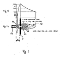
- FIG. 2 In the FIG. 2 is the burner flame 16 ( FIG. 2b ) in relation to a flame temperature curve ( FIG. 2a ). Furthermore, the distance ds between the tip of the burner head 12 and the workpiece 3 is shown. I'm in the FIG. 2 As shown, the burner 1 was set to a neutral flame setting. As can be seen, the burner flame 16 is divided from the burner head 12 into a first inner section 20, which is followed by a middle section of high firing temperatures lying between the points 21, 22, and in an adjoining outer section 23. The best Efficiency in autogenous cutting and joining is achieved when the workpiece 3 is far enough away from the tip of the burner head 12 that the workpiece lies in the region of the central section of the burner flame 16. In this area, the highest temperatures are reached, so that the highest possible operating speed can be achieved.
- the FIG. 2 also gives the in the burner flame 16 ongoing chemical reactions during the combustion of acetylene gas again. As can be seen, however, it can not be deduced from the chemical equations that an ionization of atoms within the burner flame 16 occurs during combustion.
- the gases used are naturally insulators.
- the ions resulting from ionization are either negatively or positively charged in nature.
- the negatively charged ions are z. B. in the case of a resistance measurement when applying a voltage potential for a current flow available.
- the autogenous burner flame 16 can be used to conduct an electric current. The consequence of this is that the burner flame 16 has an electrical resistance due to the dimension of the ion current, which differs depending on its size.
- the electric current is known to be the path of least resistance. During a workpiece contact of the burner flame 16, a portion of this electrical current will flow off the ion stream following the workpiece 3. This results in a relationship between electrical characteristics of the burner flame 16 and the distance d.
- an electrical voltage measurement To determine the distance size is carried out an electrical voltage measurement.
- a voltmeter is to be connected on the one hand to the electrical connection 2 of the burner 1 and on the other hand to the workpiece 3.
- the potential difference between the burner 1 and the workpiece 3 is measured.
- a connection to the respective workpiece 3 for example, a connection to a cutting table on which workpieces are to be processed take place.
- the cutting table is usually placed at ground potential.
- the result of such an electrical voltage measurement is shown. Visible is the course of the measured electrical voltage u over the distance ds, which was varied in the course of the measurement.
- the measurement result according to FIG. 3 was achieved by determining a plurality of measurements for each distance value ds to compensate for statistical variations.
- the measured voltage u typically has a stroke of several volts over the range of variation of the distance ds.
- the distance variable f (d) or the distance ds can thus be determined directly from the detected electrical voltage u.
- the value of the voltage u can be used directly as a distance variable f (d).
- a method for controlling the distance of an autogenous burner device 1 therefore comprises the detection of the voltage u as potential difference between the burner device 1 and the workpiece 3 or another known voltage potential, the detection of the minimum 32 of the voltage curve and an automatic adjustment and control of the distance ds such that at the controlled distance ds the measured voltage u is as close as possible to the local minimum 32.
- the respective electrical voltage values differ for the different workpiece materials. However, the electrical voltage maxima and minima mentioned occur in almost all materials, which in tests on different steels or other material alloys, such as, for example, for Cu, C45, S355, brass, bronze, stainless steels and aluminum. An electrical voltage maximum 30 of about 2 V and a minimum 32 of about 0.4 V could be determined for St 60.
- unalloyed steels low-alloyed steels
- titanium aluminum
- high-alloyed steels gray cast iron, copper.
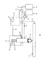
- the FIG. 4 shows an application of the invention in an autogenous burner device which is computer controlled (CNC).
- the device according to FIG. 4 initially has the autogenous burner device 1 itself on.
- the autogenous burner device 1 has the already mentioned electrical connection 2 and the hose connections 4, 5.
- the autogenous burner device 1 is connected to a computer-controlled distance control device 45.
- the pitch controller 45 includes a control microprocessor 46 and a pitch controller 47.
- the spacer 47 may be formed, for example, as an electric motor, which can adjust the autogenous burner device 1 via a spindle.
- the microprocessor 46 controls the distance controller 47.
- a detection means 40 for detecting a distance size f (d) is provided.
- the detection device 40 has its own microprocessor 41, which captures incoming data, processes and outputs accordingly.
- the detection device 40 is connected to the electrical connection 2 of the burner device 1 via a first electrical line 43. Via a second electrical line 42, the detection device 40 is electrically connected to the workpiece 3.
- the detection device 40 detects the potential difference between the electrical lines 42, 43, determines therefrom the distance variable f (d) and transmits the distance variable via a line 44 to the microprocessor 46 of the distance control device 45.
- the hose connections 4, 5 of the burner device 1 are connected via hoses 50, 51 with gas reservoirs 48, 49.
- the hoses 50, 51 are over a respective flow meter 52, 53 led to the hose connections 4, 5.
- the flow meters 52, 53 serve to detect the respective amount of gas flowing through the hose 50 or 51.
- the flow meter 52, 53 may be formed, for example, as an impeller.
- the flow meters 52, 53 are connected via electrical lines to the microprocessor 46 of the distance control device 45.
- the microprocessor 46 receives information about the gas flow rates through the hoses 50, 51 via this.
- the microprocessor 46 evaluates the received data, i. H. From this, the distance variable and the flow rates, and starting from this, advantageously sets the distance ds of the burner device 1 from the workpiece 3 such that the flame 16 strikes the workpiece 3 with its middle section (between the points 21 and 22).
- the distance control device 45 thus ensures high efficiency during autogenous separation and joining and thus enables a high feed rate of the burner device relative to the workpiece 3.
- a further application of the values of the distance variable f (d) or the distance ds obtained with the method according to the invention is that the values are recorded and used for quality documentation in manual welding.
- the described distance control includes automatic seam tracking (eg in shipbuilding) large workpiece tolerances possible.
- automatic seam tracking eg in shipbuilding
- relatively long sheets which are processed in shipbuilding in shipyards, and fail due to non-optimal heat treatment usually uneven, could be processed with the invention.
- the sheets can be arbitrarily long in principle, with sheet lengths of 2 to 20 m are not uncommon.
- a collision of a distance sensor with the workpiece, due to the unevenness can be avoided.
Landscapes
- Engineering & Computer Science (AREA)
- Mechanical Engineering (AREA)
- Lining Or Joining Of Plastics Or The Like (AREA)
- Gas Burners (AREA)
Priority Applications (2)
| Application Number | Priority Date | Filing Date | Title |
|---|---|---|---|
| SI201030349T SI2277653T1 (sl) | 2009-07-16 | 2010-07-15 | Postopek za določanje razmaka med avtogeno pripravo gorilnika in obdelovancem z zajemanjem ključne veličine brez lastne oskrbe z električno energijo |
| PL10007350T PL2277653T3 (pl) | 2009-07-16 | 2010-07-15 | Sposób określania odstępu pomiędzy autogenicznym urządzeniem palnikowym a częścią obrabianą, poprzez wykrywanie wielkości ziarna bez własnego zasilania elektryczną energią rdzenia |
Applications Claiming Priority (1)
| Application Number | Priority Date | Filing Date | Title |
|---|---|---|---|
| DE102009033556A DE102009033556A1 (de) | 2009-07-16 | 2009-07-16 | Verfahren und Vorrichtung mit einer autogenen Brennereinrichtung |
Publications (2)
| Publication Number | Publication Date |
|---|---|
| EP2277653A1 EP2277653A1 (de) | 2011-01-26 |
| EP2277653B1 true EP2277653B1 (de) | 2013-06-26 |
Family
ID=42938524
Family Applications (1)
| Application Number | Title | Priority Date | Filing Date |
|---|---|---|---|
| EP10007350.1A Not-in-force EP2277653B1 (de) | 2009-07-16 | 2010-07-15 | Verfahren zur Bestimmung des Abstands zwischen einer autogenen Brennereinrichtung und einem Werkstück durch Erfassung einer Kerngrösse ohne eine eigene elektrische Energieversorgung |
Country Status (5)
| Country | Link |
|---|---|
| EP (1) | EP2277653B1 (pl) |
| DE (1) | DE102009033556A1 (pl) |
| ES (1) | ES2428414T3 (pl) |
| PL (1) | PL2277653T3 (pl) |
| SI (1) | SI2277653T1 (pl) |
Families Citing this family (2)
| Publication number | Priority date | Publication date | Assignee | Title |
|---|---|---|---|---|
| US10067496B2 (en) * | 2013-03-15 | 2018-09-04 | The Esab Group, Inc. | Work piece condition detection using flame electrical characteristics in oxy-fuel thermal processing equipment |
| CN113084304A (zh) * | 2021-02-24 | 2021-07-09 | 宋必文 | 一种使用手工割炬的切割装置 |
Family Cites Families (12)
| Publication number | Priority date | Publication date | Assignee | Title |
|---|---|---|---|---|
| US2364645A (en) | 1942-03-31 | 1944-12-12 | Nat Cylinder Gas Co | Torch device |
| DE1220356B (de) * | 1963-09-14 | 1966-07-07 | Messer Griesheim Gmbh | Verfahren zur UEberwachung und Regelung von Flammen vorzugsweise gasfoermiger oder fluessiger Brennstoffe oder deren Wirkung |
| US3668018A (en) * | 1968-04-30 | 1972-06-06 | Iwatani & Co | Method of automatically controlling the location of a nozzle in heat treatments by hot gas flames |
| US3596892A (en) * | 1968-12-13 | 1971-08-03 | Tanaka Seisakusho Kk | Automatic gas cutting device |
| DE2724909A1 (de) * | 1977-06-02 | 1978-12-07 | Puschner Peter | Verfahren und vorrichtung zur fuehrung von gas-schneidbrennern |
| JPS6335351B2 (pl) * | 1979-03-20 | 1988-07-14 | Kyatapiraa Inc | |
| JPS5916668A (ja) * | 1983-03-07 | 1984-01-27 | Hitachi Ltd | 枝管下穴切断方法 |
| DD223956A1 (de) * | 1984-04-13 | 1985-06-26 | Zentralinstitut Schweiss | Verfahren zur automatischen akustischen steuerung des duesenabstandes von brenn- und plasmaschneidbrennern |
| DD231515A1 (de) * | 1984-12-20 | 1986-01-02 | Zentralinstitut Schweiss | Verfahren zum positionieren eines arbeitsgeraetes |
| DD249598A3 (de) * | 1985-03-18 | 1987-09-16 | Zi F Schweisstechnik Der Ddr L | Verfahren und vorrichtung der prozesskontrolle beim thermischen trennen |
| DD282802A7 (de) * | 1988-05-06 | 1990-09-26 | Zentralinstitut Schweiss | Verfahren zur regelung der brennerhoehe beim thermischen trennen |
| DE10144718A1 (de) | 2001-09-11 | 2002-05-02 | Karl Heinz Schmall | Sensorelement und Halterung für die berührungslose Abstandsregelung zwischen einem Bearbeitungswerkzeug und dem Werkstück, vorzugsweise bei Brennschneide- und Wasserstrahlschneidemaschinen |
-
2009
- 2009-07-16 DE DE102009033556A patent/DE102009033556A1/de not_active Withdrawn
-
2010
- 2010-07-15 EP EP10007350.1A patent/EP2277653B1/de not_active Not-in-force
- 2010-07-15 ES ES10007350T patent/ES2428414T3/es active Active
- 2010-07-15 PL PL10007350T patent/PL2277653T3/pl unknown
- 2010-07-15 SI SI201030349T patent/SI2277653T1/sl unknown
Also Published As
| Publication number | Publication date |
|---|---|
| DE102009033556A1 (de) | 2011-01-20 |
| SI2277653T1 (sl) | 2013-11-29 |
| PL2277653T3 (pl) | 2013-11-29 |
| ES2428414T3 (es) | 2013-11-07 |
| EP2277653A1 (de) | 2011-01-26 |
Similar Documents
| Publication | Publication Date | Title |
|---|---|---|
| DE69800465T2 (de) | Verfahren und automatische Vorrichtung zum Signieren durch Plasma, insbesondere von Metallen | |
| EP2465334B1 (de) | Düsenschutzkappe und düsenschutzkappenhalter sowie lichtbogenplasmabrenner mit derselben und/oder demselben | |
| DE19738785C2 (de) | Vorrichtung zum Lichtbogenschweißen mit abschmelzender Elektrode | |
| DE2555792A1 (de) | Verfahren zur qualitaetssicherung der schweissverbindungen beim elektrischen widerstandspunktschweissen | |
| EP2191925A1 (de) | Verfahren, Vorrichtung und Computerprogram zum Plasma-Stichlochschweißen mit aktiver Veränderung des Durchdringungsstroms während des Schweissens | |
| EP2644306A1 (de) | Schweißvorrichtung und ein Verfahren zur Regelung eines Schweißprozesses | |
| WO2005007332A1 (de) | Verfahren zur versorgung eines plasmabrenners mit einem gas, mischgas oder gasgemisch mit durchführung der volumenstromregelung in kombination mit einer druckregelung; anordnung zur durchführung dieses verfahrens | |
| DE1237713B (de) | Verfahren und Vorrichtung zur Metallbearbeitung mittels Elektro-Erosion | |
| DE2703113C3 (de) | Verfahren und Vorrichtung zur Regelung der Leistung eines Lichtbogen-Schweißbrenners | |
| DE102008028385B4 (de) | Mess- und Steuerverfahren zum Widerstandsschweißen | |
| EP2277653A1 (de) | Verfahren zur Bestimmung des Abstands zwischen einer autogenen Brennereinrichtung und einem Werkstück durch Erfassung einer Kerngrösse ohne eine eigene elektrische Energieversorgung | |
| DE102021123839A1 (de) | Verfahren zur Überwachung eines Brennschneidprozesses | |
| EP3712501B1 (de) | Verfahren und vorrichtung zur regeneration einer elektrode für eine ionisationsmessung in einem flammbereich eines brenners | |
| EP1641587A1 (de) | Verfahren und vorrichtung zur gewinnung von informationen zur beurteilung der qualität einer widerstandsschweissverbindung und/oder zur steuerung oder regelung eines widerstandsschweissverfahrens | |
| DE2850978C2 (de) | Verfahren zum Regeln des Schweißvorganges bei der Herstellung von Längsnahtrohren | |
| DE3504936A1 (de) | Stromdichte-steuervorrichtung | |
| DE1900509C3 (de) | Verfahren und Vorrichtung zum Regeln des Schweißvorganges beim einseitigen Lichtbogen-Verbindungssehweißen | |
| DE1966696C3 (de) | Verfahren zum elektrischen Widerstand sabbrennstumpfschweißen | |
| EP0977647A1 (de) | Verfahren und vorrichtung zur erfassung der arbeitsspannung an schweissstromquellen | |
| DE102017211725B4 (de) | Verfahren zur Herstellung einer Schweißverbindung | |
| DE1900856B2 (de) | Verfahren zur automatischen regelung der gleichstromlicht bogenschweissung duenner bleche | |
| DE102015010734A1 (de) | Vorrichtung und Verfahren zur niederohmigen Verschweißung von Blechen mit hoher Taktzahl | |
| EP2105235A1 (de) | Verfahren und Vorrichtung zur funkenerosiven Bearbeitung eines elektrisch nich leitenden Materials | |
| EP4122631A1 (de) | Verfahren zur überwachung eines brennschneidprozesses | |
| WO2024002994A1 (de) | Schweissverfahren und schweissvorrichtung |
Legal Events
| Date | Code | Title | Description |
|---|---|---|---|
| PUAI | Public reference made under article 153(3) epc to a published international application that has entered the european phase |
Free format text: ORIGINAL CODE: 0009012 |
|
| AK | Designated contracting states |
Kind code of ref document: A1 Designated state(s): AL AT BE BG CH CY CZ DE DK EE ES FI FR GB GR HR HU IE IS IT LI LT LU LV MC MK MT NL NO PL PT RO SE SI SK SM TR |
|
| AX | Request for extension of the european patent |
Extension state: BA ME RS |
|
| RIN1 | Information on inventor provided before grant (corrected) |
Inventor name: BIERBAUM, MARTEN Inventor name: BACH, FRIEDRICH-WILHELM, PROF. DR.-ING. Inventor name: KRINK, VOLKER Inventor name: HASSEL, THOMAS |
|
| 17P | Request for examination filed |
Effective date: 20110722 |
|
| GRAP | Despatch of communication of intention to grant a patent |
Free format text: ORIGINAL CODE: EPIDOSNIGR1 |
|
| GRAS | Grant fee paid |
Free format text: ORIGINAL CODE: EPIDOSNIGR3 |
|
| GRAA | (expected) grant |
Free format text: ORIGINAL CODE: 0009210 |
|
| AK | Designated contracting states |
Kind code of ref document: B1 Designated state(s): AL AT BE BG CH CY CZ DE DK EE ES FI FR GB GR HR HU IE IS IT LI LT LU LV MC MK MT NL NO PL PT RO SE SI SK SM TR |
|
| REG | Reference to a national code |
Ref country code: GB Ref legal event code: FG4D Free format text: NOT ENGLISH |
|
| REG | Reference to a national code |
Ref country code: CH Ref legal event code: EP |
|
| REG | Reference to a national code |
Ref country code: AT Ref legal event code: REF Ref document number: 618466 Country of ref document: AT Kind code of ref document: T Effective date: 20130715 |
|
| REG | Reference to a national code |
Ref country code: IE Ref legal event code: FG4D Free format text: LANGUAGE OF EP DOCUMENT: GERMAN |
|
| REG | Reference to a national code |
Ref country code: DE Ref legal event code: R096 Ref document number: 502010003766 Country of ref document: DE Effective date: 20130822 |
|
| REG | Reference to a national code |
Ref country code: SE Ref legal event code: TRGR |
|
| REG | Reference to a national code |
Ref country code: NL Ref legal event code: T3 |
|
| PG25 | Lapsed in a contracting state [announced via postgrant information from national office to epo] |
Ref country code: NO Free format text: LAPSE BECAUSE OF FAILURE TO SUBMIT A TRANSLATION OF THE DESCRIPTION OR TO PAY THE FEE WITHIN THE PRESCRIBED TIME-LIMIT Effective date: 20130926 Ref country code: FI Free format text: LAPSE BECAUSE OF FAILURE TO SUBMIT A TRANSLATION OF THE DESCRIPTION OR TO PAY THE FEE WITHIN THE PRESCRIBED TIME-LIMIT Effective date: 20130626 Ref country code: LT Free format text: LAPSE BECAUSE OF FAILURE TO SUBMIT A TRANSLATION OF THE DESCRIPTION OR TO PAY THE FEE WITHIN THE PRESCRIBED TIME-LIMIT Effective date: 20130626 Ref country code: GR Free format text: LAPSE BECAUSE OF FAILURE TO SUBMIT A TRANSLATION OF THE DESCRIPTION OR TO PAY THE FEE WITHIN THE PRESCRIBED TIME-LIMIT Effective date: 20130927 |
|
| PGFP | Annual fee paid to national office [announced via postgrant information from national office to epo] |
Ref country code: SI Payment date: 20130704 Year of fee payment: 4 |
|
| REG | Reference to a national code |
Ref country code: ES Ref legal event code: FG2A Ref document number: 2428414 Country of ref document: ES Kind code of ref document: T3 Effective date: 20131107 |
|
| REG | Reference to a national code |
Ref country code: LT Ref legal event code: MG4D |
|
| PG25 | Lapsed in a contracting state [announced via postgrant information from national office to epo] |
Ref country code: BG Free format text: LAPSE BECAUSE OF FAILURE TO SUBMIT A TRANSLATION OF THE DESCRIPTION OR TO PAY THE FEE WITHIN THE PRESCRIBED TIME-LIMIT Effective date: 20130926 Ref country code: HR Free format text: LAPSE BECAUSE OF FAILURE TO SUBMIT A TRANSLATION OF THE DESCRIPTION OR TO PAY THE FEE WITHIN THE PRESCRIBED TIME-LIMIT Effective date: 20130626 |
|
| PGFP | Annual fee paid to national office [announced via postgrant information from national office to epo] |
Ref country code: SE Payment date: 20130819 Year of fee payment: 4 |
|
| REG | Reference to a national code |
Ref country code: PL Ref legal event code: T3 |
|
| REG | Reference to a national code |
Ref country code: SK Ref legal event code: T3 Ref document number: E 14822 Country of ref document: SK |
|
| PG25 | Lapsed in a contracting state [announced via postgrant information from national office to epo] |
Ref country code: LV Free format text: LAPSE BECAUSE OF FAILURE TO SUBMIT A TRANSLATION OF THE DESCRIPTION OR TO PAY THE FEE WITHIN THE PRESCRIBED TIME-LIMIT Effective date: 20130626 |
|
| PG25 | Lapsed in a contracting state [announced via postgrant information from national office to epo] |
Ref country code: PT Free format text: LAPSE BECAUSE OF FAILURE TO SUBMIT A TRANSLATION OF THE DESCRIPTION OR TO PAY THE FEE WITHIN THE PRESCRIBED TIME-LIMIT Effective date: 20131028 Ref country code: CY Free format text: LAPSE BECAUSE OF FAILURE TO SUBMIT A TRANSLATION OF THE DESCRIPTION OR TO PAY THE FEE WITHIN THE PRESCRIBED TIME-LIMIT Effective date: 20130918 Ref country code: IS Free format text: LAPSE BECAUSE OF FAILURE TO SUBMIT A TRANSLATION OF THE DESCRIPTION OR TO PAY THE FEE WITHIN THE PRESCRIBED TIME-LIMIT Effective date: 20131026 Ref country code: EE Free format text: LAPSE BECAUSE OF FAILURE TO SUBMIT A TRANSLATION OF THE DESCRIPTION OR TO PAY THE FEE WITHIN THE PRESCRIBED TIME-LIMIT Effective date: 20130626 |
|
| PG25 | Lapsed in a contracting state [announced via postgrant information from national office to epo] |
Ref country code: RO Free format text: LAPSE BECAUSE OF FAILURE TO SUBMIT A TRANSLATION OF THE DESCRIPTION OR TO PAY THE FEE WITHIN THE PRESCRIBED TIME-LIMIT Effective date: 20130626 |
|
| PG25 | Lapsed in a contracting state [announced via postgrant information from national office to epo] |
Ref country code: MC Free format text: LAPSE BECAUSE OF FAILURE TO SUBMIT A TRANSLATION OF THE DESCRIPTION OR TO PAY THE FEE WITHIN THE PRESCRIBED TIME-LIMIT Effective date: 20130626 Ref country code: CY Free format text: LAPSE BECAUSE OF FAILURE TO SUBMIT A TRANSLATION OF THE DESCRIPTION OR TO PAY THE FEE WITHIN THE PRESCRIBED TIME-LIMIT Effective date: 20130626 |
|
| REG | Reference to a national code |
Ref country code: IE Ref legal event code: MM4A |
|
| PG25 | Lapsed in a contracting state [announced via postgrant information from national office to epo] |
Ref country code: DK Free format text: LAPSE BECAUSE OF FAILURE TO SUBMIT A TRANSLATION OF THE DESCRIPTION OR TO PAY THE FEE WITHIN THE PRESCRIBED TIME-LIMIT Effective date: 20130626 |
|
| PLBE | No opposition filed within time limit |
Free format text: ORIGINAL CODE: 0009261 |
|
| STAA | Information on the status of an ep patent application or granted ep patent |
Free format text: STATUS: NO OPPOSITION FILED WITHIN TIME LIMIT |
|
| 26N | No opposition filed |
Effective date: 20140327 |
|
| REG | Reference to a national code |
Ref country code: DE Ref legal event code: R097 Ref document number: 502010003766 Country of ref document: DE Effective date: 20140327 |
|
| PG25 | Lapsed in a contracting state [announced via postgrant information from national office to epo] |
Ref country code: IE Free format text: LAPSE BECAUSE OF NON-PAYMENT OF DUE FEES Effective date: 20130715 |
|
| PGFP | Annual fee paid to national office [announced via postgrant information from national office to epo] |
Ref country code: CZ Payment date: 20140714 Year of fee payment: 5 Ref country code: NL Payment date: 20140721 Year of fee payment: 5 |
|
| PGFP | Annual fee paid to national office [announced via postgrant information from national office to epo] |
Ref country code: TR Payment date: 20140715 Year of fee payment: 5 Ref country code: SK Payment date: 20140714 Year of fee payment: 5 |
|
| PGFP | Annual fee paid to national office [announced via postgrant information from national office to epo] |
Ref country code: IT Payment date: 20140724 Year of fee payment: 5 |
|
| PGFP | Annual fee paid to national office [announced via postgrant information from national office to epo] |
Ref country code: BE Payment date: 20140722 Year of fee payment: 5 |
|
| REG | Reference to a national code |
Ref country code: CH Ref legal event code: PL |
|
| REG | Reference to a national code |
Ref country code: SE Ref legal event code: EUG |
|
| GBPC | Gb: european patent ceased through non-payment of renewal fee |
Effective date: 20140715 |
|
| PG25 | Lapsed in a contracting state [announced via postgrant information from national office to epo] |
Ref country code: CH Free format text: LAPSE BECAUSE OF NON-PAYMENT OF DUE FEES Effective date: 20140731 Ref country code: LI Free format text: LAPSE BECAUSE OF NON-PAYMENT OF DUE FEES Effective date: 20140731 |
|
| REG | Reference to a national code |
Ref country code: SI Ref legal event code: KO00 Effective date: 20150317 |
|
| PG25 | Lapsed in a contracting state [announced via postgrant information from national office to epo] |
Ref country code: SE Free format text: LAPSE BECAUSE OF NON-PAYMENT OF DUE FEES Effective date: 20140716 Ref country code: SI Free format text: LAPSE BECAUSE OF NON-PAYMENT OF DUE FEES Effective date: 20140716 Ref country code: GB Free format text: LAPSE BECAUSE OF NON-PAYMENT OF DUE FEES Effective date: 20140715 Ref country code: SM Free format text: LAPSE BECAUSE OF FAILURE TO SUBMIT A TRANSLATION OF THE DESCRIPTION OR TO PAY THE FEE WITHIN THE PRESCRIBED TIME-LIMIT Effective date: 20130626 |
|
| PG25 | Lapsed in a contracting state [announced via postgrant information from national office to epo] |
Ref country code: MT Free format text: LAPSE BECAUSE OF FAILURE TO SUBMIT A TRANSLATION OF THE DESCRIPTION OR TO PAY THE FEE WITHIN THE PRESCRIBED TIME-LIMIT Effective date: 20130626 |
|
| REG | Reference to a national code |
Ref country code: FR Ref legal event code: PLFP Year of fee payment: 6 |
|
| PG25 | Lapsed in a contracting state [announced via postgrant information from national office to epo] |
Ref country code: HU Free format text: LAPSE BECAUSE OF FAILURE TO SUBMIT A TRANSLATION OF THE DESCRIPTION OR TO PAY THE FEE WITHIN THE PRESCRIBED TIME-LIMIT; INVALID AB INITIO Effective date: 20100715 Ref country code: MK Free format text: LAPSE BECAUSE OF FAILURE TO SUBMIT A TRANSLATION OF THE DESCRIPTION OR TO PAY THE FEE WITHIN THE PRESCRIBED TIME-LIMIT Effective date: 20130626 Ref country code: LU Free format text: LAPSE BECAUSE OF NON-PAYMENT OF DUE FEES Effective date: 20130715 |
|
| PGFP | Annual fee paid to national office [announced via postgrant information from national office to epo] |
Ref country code: ES Payment date: 20150728 Year of fee payment: 6 Ref country code: DE Payment date: 20150730 Year of fee payment: 6 |
|
| PGFP | Annual fee paid to national office [announced via postgrant information from national office to epo] |
Ref country code: PL Payment date: 20150714 Year of fee payment: 6 Ref country code: FR Payment date: 20150722 Year of fee payment: 6 |
|
| REG | Reference to a national code |
Ref country code: SK Ref legal event code: MM4A Ref document number: E 14822 Country of ref document: SK Effective date: 20150715 |
|
| REG | Reference to a national code |
Ref country code: NL Ref legal event code: MM Effective date: 20150801 |
|
| PG25 | Lapsed in a contracting state [announced via postgrant information from national office to epo] |
Ref country code: SK Free format text: LAPSE BECAUSE OF NON-PAYMENT OF DUE FEES Effective date: 20150715 Ref country code: CZ Free format text: LAPSE BECAUSE OF NON-PAYMENT OF DUE FEES Effective date: 20150715 Ref country code: IT Free format text: LAPSE BECAUSE OF NON-PAYMENT OF DUE FEES Effective date: 20150715 |
|
| PG25 | Lapsed in a contracting state [announced via postgrant information from national office to epo] |
Ref country code: NL Free format text: LAPSE BECAUSE OF NON-PAYMENT OF DUE FEES Effective date: 20150801 |
|
| REG | Reference to a national code |
Ref country code: AT Ref legal event code: MM01 Ref document number: 618466 Country of ref document: AT Kind code of ref document: T Effective date: 20150715 |
|
| PG25 | Lapsed in a contracting state [announced via postgrant information from national office to epo] |
Ref country code: AT Free format text: LAPSE BECAUSE OF NON-PAYMENT OF DUE FEES Effective date: 20150715 |
|
| REG | Reference to a national code |
Ref country code: DE Ref legal event code: R119 Ref document number: 502010003766 Country of ref document: DE |
|
| PG25 | Lapsed in a contracting state [announced via postgrant information from national office to epo] |
Ref country code: DE Free format text: LAPSE BECAUSE OF NON-PAYMENT OF DUE FEES Effective date: 20170201 Ref country code: FR Free format text: LAPSE BECAUSE OF NON-PAYMENT OF DUE FEES Effective date: 20160801 |
|
| REG | Reference to a national code |
Ref country code: FR Ref legal event code: ST Effective date: 20170331 |
|
| PG25 | Lapsed in a contracting state [announced via postgrant information from national office to epo] |
Ref country code: BE Free format text: LAPSE BECAUSE OF NON-PAYMENT OF DUE FEES Effective date: 20150731 |
|
| PG25 | Lapsed in a contracting state [announced via postgrant information from national office to epo] |
Ref country code: TR Free format text: LAPSE BECAUSE OF NON-PAYMENT OF DUE FEES Effective date: 20150715 |
|
| PG25 | Lapsed in a contracting state [announced via postgrant information from national office to epo] |
Ref country code: PL Free format text: LAPSE BECAUSE OF NON-PAYMENT OF DUE FEES Effective date: 20160715 |
|
| PG25 | Lapsed in a contracting state [announced via postgrant information from national office to epo] |
Ref country code: ES Free format text: LAPSE BECAUSE OF NON-PAYMENT OF DUE FEES Effective date: 20160716 |
|
| REG | Reference to a national code |
Ref country code: ES Ref legal event code: FD2A Effective date: 20180625 |
|
| PG25 | Lapsed in a contracting state [announced via postgrant information from national office to epo] |
Ref country code: AL Free format text: LAPSE BECAUSE OF FAILURE TO SUBMIT A TRANSLATION OF THE DESCRIPTION OR TO PAY THE FEE WITHIN THE PRESCRIBED TIME-LIMIT Effective date: 20130626 |