EP2277477B1 - Intraluminal stent - Google Patents
Intraluminal stent Download PDFInfo
- Publication number
- EP2277477B1 EP2277477B1 EP10172426A EP10172426A EP2277477B1 EP 2277477 B1 EP2277477 B1 EP 2277477B1 EP 10172426 A EP10172426 A EP 10172426A EP 10172426 A EP10172426 A EP 10172426A EP 2277477 B1 EP2277477 B1 EP 2277477B1
- Authority
- EP
- European Patent Office
- Prior art keywords
- stent
- zig
- adjacent
- hoop
- hoops
- Prior art date
- Legal status (The legal status is an assumption and is not a legal conclusion. Google has not performed a legal analysis and makes no representation as to the accuracy of the status listed.)
- Expired - Lifetime
Links
- 238000004804 winding Methods 0.000 description 15
- 230000007704 transition Effects 0.000 description 12
- HLXZNVUGXRDIFK-UHFFFAOYSA-N nickel titanium Chemical compound [Ti].[Ti].[Ti].[Ti].[Ti].[Ti].[Ti].[Ti].[Ti].[Ti].[Ti].[Ni].[Ni].[Ni].[Ni].[Ni].[Ni].[Ni].[Ni].[Ni].[Ni].[Ni].[Ni].[Ni].[Ni] HLXZNVUGXRDIFK-UHFFFAOYSA-N 0.000 description 10
- 229910001000 nickel titanium Inorganic materials 0.000 description 10
- 238000003780 insertion Methods 0.000 description 7
- 230000037431 insertion Effects 0.000 description 7
- 239000000463 material Substances 0.000 description 6
- 238000000137 annealing Methods 0.000 description 5
- 238000005520 cutting process Methods 0.000 description 5
- 230000000694 effects Effects 0.000 description 5
- 239000003550 marker Substances 0.000 description 5
- 229910000734 martensite Inorganic materials 0.000 description 5
- 238000000034 method Methods 0.000 description 5
- 238000003466 welding Methods 0.000 description 5
- 238000004519 manufacturing process Methods 0.000 description 4
- 229910001566 austenite Inorganic materials 0.000 description 3
- RVTZCBVAJQQJTK-UHFFFAOYSA-N oxygen(2-);zirconium(4+) Chemical compound [O-2].[O-2].[Zr+4] RVTZCBVAJQQJTK-UHFFFAOYSA-N 0.000 description 3
- 208000031481 Pathologic Constriction Diseases 0.000 description 2
- 238000004026 adhesive bonding Methods 0.000 description 2
- 230000015572 biosynthetic process Effects 0.000 description 2
- 230000006835 compression Effects 0.000 description 2
- 238000007906 compression Methods 0.000 description 2
- 239000003292 glue Substances 0.000 description 2
- 229920000642 polymer Polymers 0.000 description 2
- 229910001220 stainless steel Inorganic materials 0.000 description 2
- 239000010935 stainless steel Substances 0.000 description 2
- 239000000126 substance Substances 0.000 description 2
- 229920001169 thermoplastic Polymers 0.000 description 2
- 206010002329 Aneurysm Diseases 0.000 description 1
- 208000007536 Thrombosis Diseases 0.000 description 1
- 238000004873 anchoring Methods 0.000 description 1
- 230000004323 axial length Effects 0.000 description 1
- 239000008280 blood Substances 0.000 description 1
- 210000004369 blood Anatomy 0.000 description 1
- 230000017531 blood circulation Effects 0.000 description 1
- 238000001816 cooling Methods 0.000 description 1
- 230000007423 decrease Effects 0.000 description 1
- 230000001419 dependent effect Effects 0.000 description 1
- 201000010099 disease Diseases 0.000 description 1
- 208000037265 diseases, disorders, signs and symptoms Diseases 0.000 description 1
- 238000010438 heat treatment Methods 0.000 description 1
- 238000002513 implantation Methods 0.000 description 1
- 230000007246 mechanism Effects 0.000 description 1
- BASFCYQUMIYNBI-UHFFFAOYSA-N platinum Chemical compound [Pt] BASFCYQUMIYNBI-UHFFFAOYSA-N 0.000 description 1
- 230000000087 stabilizing effect Effects 0.000 description 1
Images


Classifications
-
- A—HUMAN NECESSITIES
- A61—MEDICAL OR VETERINARY SCIENCE; HYGIENE
- A61F—FILTERS IMPLANTABLE INTO BLOOD VESSELS; PROSTHESES; DEVICES PROVIDING PATENCY TO, OR PREVENTING COLLAPSING OF, TUBULAR STRUCTURES OF THE BODY, e.g. STENTS; ORTHOPAEDIC, NURSING OR CONTRACEPTIVE DEVICES; FOMENTATION; TREATMENT OR PROTECTION OF EYES OR EARS; BANDAGES, DRESSINGS OR ABSORBENT PADS; FIRST-AID KITS
- A61F2/00—Filters implantable into blood vessels; Prostheses, i.e. artificial substitutes or replacements for parts of the body; Appliances for connecting them with the body; Devices providing patency to, or preventing collapsing of, tubular structures of the body, e.g. stents
- A61F2/82—Devices providing patency to, or preventing collapsing of, tubular structures of the body, e.g. stents
- A61F2/86—Stents in a form characterised by the wire-like elements; Stents in the form characterised by a net-like or mesh-like structure
- A61F2/88—Stents in a form characterised by the wire-like elements; Stents in the form characterised by a net-like or mesh-like structure the wire-like elements formed as helical or spiral coils
-
- A—HUMAN NECESSITIES
- A61—MEDICAL OR VETERINARY SCIENCE; HYGIENE
- A61F—FILTERS IMPLANTABLE INTO BLOOD VESSELS; PROSTHESES; DEVICES PROVIDING PATENCY TO, OR PREVENTING COLLAPSING OF, TUBULAR STRUCTURES OF THE BODY, e.g. STENTS; ORTHOPAEDIC, NURSING OR CONTRACEPTIVE DEVICES; FOMENTATION; TREATMENT OR PROTECTION OF EYES OR EARS; BANDAGES, DRESSINGS OR ABSORBENT PADS; FIRST-AID KITS
- A61F2/00—Filters implantable into blood vessels; Prostheses, i.e. artificial substitutes or replacements for parts of the body; Appliances for connecting them with the body; Devices providing patency to, or preventing collapsing of, tubular structures of the body, e.g. stents
- A61F2/82—Devices providing patency to, or preventing collapsing of, tubular structures of the body, e.g. stents
- A61F2/86—Stents in a form characterised by the wire-like elements; Stents in the form characterised by a net-like or mesh-like structure
- A61F2/90—Stents in a form characterised by the wire-like elements; Stents in the form characterised by a net-like or mesh-like structure characterised by a net-like or mesh-like structure
-
- A—HUMAN NECESSITIES
- A61—MEDICAL OR VETERINARY SCIENCE; HYGIENE
- A61F—FILTERS IMPLANTABLE INTO BLOOD VESSELS; PROSTHESES; DEVICES PROVIDING PATENCY TO, OR PREVENTING COLLAPSING OF, TUBULAR STRUCTURES OF THE BODY, e.g. STENTS; ORTHOPAEDIC, NURSING OR CONTRACEPTIVE DEVICES; FOMENTATION; TREATMENT OR PROTECTION OF EYES OR EARS; BANDAGES, DRESSINGS OR ABSORBENT PADS; FIRST-AID KITS
- A61F2/00—Filters implantable into blood vessels; Prostheses, i.e. artificial substitutes or replacements for parts of the body; Appliances for connecting them with the body; Devices providing patency to, or preventing collapsing of, tubular structures of the body, e.g. stents
- A61F2/02—Prostheses implantable into the body
- A61F2/30—Joints
- A61F2002/30001—Additional features of subject-matter classified in A61F2/28, A61F2/30 and subgroups thereof
- A61F2002/30316—The prosthesis having different structural features at different locations within the same prosthesis; Connections between prosthetic parts; Special structural features of bone or joint prostheses not otherwise provided for
- A61F2002/30317—The prosthesis having different structural features at different locations within the same prosthesis
- A61F2002/30322—The prosthesis having different structural features at different locations within the same prosthesis differing in surface structures
-
- A—HUMAN NECESSITIES
- A61—MEDICAL OR VETERINARY SCIENCE; HYGIENE
- A61F—FILTERS IMPLANTABLE INTO BLOOD VESSELS; PROSTHESES; DEVICES PROVIDING PATENCY TO, OR PREVENTING COLLAPSING OF, TUBULAR STRUCTURES OF THE BODY, e.g. STENTS; ORTHOPAEDIC, NURSING OR CONTRACEPTIVE DEVICES; FOMENTATION; TREATMENT OR PROTECTION OF EYES OR EARS; BANDAGES, DRESSINGS OR ABSORBENT PADS; FIRST-AID KITS
- A61F2/00—Filters implantable into blood vessels; Prostheses, i.e. artificial substitutes or replacements for parts of the body; Appliances for connecting them with the body; Devices providing patency to, or preventing collapsing of, tubular structures of the body, e.g. stents
- A61F2/82—Devices providing patency to, or preventing collapsing of, tubular structures of the body, e.g. stents
- A61F2002/828—Means for connecting a plurality of stents allowing flexibility of the whole structure
-
- A—HUMAN NECESSITIES
- A61—MEDICAL OR VETERINARY SCIENCE; HYGIENE
- A61F—FILTERS IMPLANTABLE INTO BLOOD VESSELS; PROSTHESES; DEVICES PROVIDING PATENCY TO, OR PREVENTING COLLAPSING OF, TUBULAR STRUCTURES OF THE BODY, e.g. STENTS; ORTHOPAEDIC, NURSING OR CONTRACEPTIVE DEVICES; FOMENTATION; TREATMENT OR PROTECTION OF EYES OR EARS; BANDAGES, DRESSINGS OR ABSORBENT PADS; FIRST-AID KITS
- A61F2250/00—Special features of prostheses classified in groups A61F2/00 - A61F2/26 or A61F2/82 or A61F9/00 or A61F11/00 or subgroups thereof
- A61F2250/0014—Special features of prostheses classified in groups A61F2/00 - A61F2/26 or A61F2/82 or A61F9/00 or A61F11/00 or subgroups thereof having different values of a given property or geometrical feature, e.g. mechanical property or material property, at different locations within the same prosthesis
- A61F2250/0026—Special features of prostheses classified in groups A61F2/00 - A61F2/26 or A61F2/82 or A61F9/00 or A61F11/00 or subgroups thereof having different values of a given property or geometrical feature, e.g. mechanical property or material property, at different locations within the same prosthesis differing in surface structures
-
- A—HUMAN NECESSITIES
- A61—MEDICAL OR VETERINARY SCIENCE; HYGIENE
- A61F—FILTERS IMPLANTABLE INTO BLOOD VESSELS; PROSTHESES; DEVICES PROVIDING PATENCY TO, OR PREVENTING COLLAPSING OF, TUBULAR STRUCTURES OF THE BODY, e.g. STENTS; ORTHOPAEDIC, NURSING OR CONTRACEPTIVE DEVICES; FOMENTATION; TREATMENT OR PROTECTION OF EYES OR EARS; BANDAGES, DRESSINGS OR ABSORBENT PADS; FIRST-AID KITS
- A61F2250/00—Special features of prostheses classified in groups A61F2/00 - A61F2/26 or A61F2/82 or A61F9/00 or A61F11/00 or subgroups thereof
- A61F2250/0058—Additional features; Implant or prostheses properties not otherwise provided for
- A61F2250/006—Additional features; Implant or prostheses properties not otherwise provided for modular
Definitions
- wire 11 is wound around pins 13 on a mandrel (not shown).
- the mandrel is typically cylindrical (although other shapes may be used as necessary to form stents of varying shapes) and of a diameter determined by the diameter of the vessel into which stent 10 is to be inserted.
- the mandrel diameter, and hence the intended diameter of stent 10 is slightly larger (for example, by one millimeter) than the diameter of the vessel.
- the length of stent 10 is also determined by the particular application.
- Stent 10 is formed by winding wire 11 around pins 13 beginning at point A in FIG. 1 .
- Wire 11 is extended to and around pins 13a, 13b, 13c and so forth.
- zig-zag members are formed and defined by a successive series of substantially straight sections (struts) 14 connected by apex sections 15 alternately pointing in opposite axial directions.
- the winding continues in this manner around the mandrel until a first hoop member 12a is completed by winding wire 11 once around the circumference of the mandrel.
- Hoop member 12a as shown in FIG. 1 has a circumference lying in a plane substantially perpendicular to the axis of the mandrel (and hence of stent 10 ).
- first hoop member 12a Once a first hoop member 12a is formed, wire 11 is extended from pin 13d to and around pin 13e. Winding then continues as before to form a second hoop member 12b adjacent to first hoop member 12a. By forming hoop members in this manner, adjacent hoops 12a and 12b are connected by the portion of wire 11 extending between first hoop member 12a and second hoop member 12b. At the completion of the second hoop member 12b, wire 11 is again extended to the third hoop member 12c, which is wound as before, and so forth until the desired number N of hoop members for are formed along the length of stent 10. Thus, as shown in FIG.
- the winding extends in a serves of hoops between hoops 12a and hoop 12N, with the wire beginning at point A and ending at point B.
- wire 11 is typically cut so that the wire terminates short of points A and B, generally terminating within the first hoop 12a and last hoop 12N, respectively, as described with reference to FIG. 6C herein later.
- Stent 10 is removed from the mandrel and pins 13a, 13b, 13c, etc., prior to use.
- each hoop member 12 has one pair of aligned, adjacent struts 14a and 14b. Aligned, adjacent struts 14a and 14b of the same hoop may be welded together. Such welding may be spot welding along the length of aligned, adjacent struts 14a and 14b, or it may be a continuous weld. In either case, a welded, connective spine 16 is formed along the perimeter of stent 10. Connective spine 16 typically winds around the circumference of stent 10 in an offset helical fashion (the embodiment shown flat in FIG. 1 being cylindrical or tubular in actual use).
- Connective spine 16 provides strength and stability to stent 10 while preserving the flexibility of stent 10. During insertion of stent 10 into a vessel (described below), connective spine 16 renders stent 10 easier to push through a catheter.
- connective spine 16 may be formed by connecting aligned, adjacent struts 14a and 14b according to any other suitable attachment means, including without limitation, tying, suturing, gluing, and stapling, with the glue or sutures being absorbable or non-absorbable, and including the use of polymer-containing connections.
- stent 10 comprises thermally expandable nitinol
- stent 10 is annealed before removal from the mandrel and pins 13a, 13b, 13c, etc., at an annealing temperature for about one hour and then allowed to cool.
- This annealing temperature is desirably on the order of about 500°C, although any temperature sufficient to effect annealment of stent 10 will suffice.
- stent 10 is removed from the mandrel on which it is wound to compress stent 10 into a configuration for introduction to a body passageway. Then, it is cooled to below its martensitic transition temperature. In this phase, nitinol is malleable and has virtually no resiliency. Thus, it can be easily compressed. Stent 10 can be easily returned to its annealed shape by heating it to a temperature above its austenite transition temperature. Above this temperature, the stent resumes its annealed configuration.
- the mandrel peg at each lettered point may be considered to be one of a set of pegs corresponding to the wire to wound about the set.
- pegs at points A , B , C , etc. above are a part of one set
- pegs E, Q, R, etc. above are part of a second set.
- Each set contains at least one common peg (for example, F in the first set and W in the second set) where both wires follow a common path between the common pegs of the circumferentially adjoining sets.
- the wires that form the common path are connected as described above.
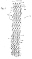
- FIG. 3 illustrates another stent wherein the zig length L 1 is varied within stent 10B.
- Zig length L 1 is the distance between apex sections 15 ' and 15 " measured in a direction parallel to the stent axis (vertical, in FIG. 3 ).
- the zig length may similarly be described as the amplitude of a sinusoidally shaped zig-zag.
- the zig length at end sections 22 of stent 10B may be relatively short (relatively small amplitude), while the zigs in middle section 20 of stent 10B are relatively long (having greater amplitude).
- a "zig" is considered to be the part of wire 11 extending from, for example, point X to point Y to point Z.
- X-Y-Z in FIG. 1 is considered to represent one zig.
- each similarly-oriented apex section i.e. each apex section pointing in the same direction
- the number of zigs in a hoop may be similarly described as the number of periods of a sinusoidally shaped zig-zag.
- each hoop member has five zigs.
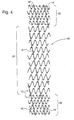
- FIG. 4 illustrates an alternative stent, not drawn to scale, wherein the center portion 20 of stent 10 has four zigs per hoop member 12 , a first zig length, and one connective spine 16; and the end portions 22 have six zigs per hoop member 12, a second zig length, and two connective spines 16 .
- the second spines on both ends overlap two hoop members 12 of the center portion as a transition.
- the number of connective spines 16 can thus be varied within a stent to provide a more rigid portion at the ends and a more flexible portion in the middle.
- wire diameter 8 may have, for example, a wire diameter of 0.007 inches, a 6.4 mm OD, a 6 mm ID, and a length of 100 mm.
- Other wire diameters slightly larger than 0.007 inches such as 0.008 or 0.009 inches, for example, will suffice.
- another method of making connecting members may comprise axially opposed apex sections 15 of adjacent hoops 12 being axially spaced from one another with one or both of the first and second struts 14' of the connecting member elongated relative to the remainder of the struts 14 in the adjacent hoops.
- Such elongated struts 14' may thus lie adjacent one another for at least some axial distance to permit connection therebetween.
- adjacent hoops are connected by a separate bridging member 26 adjacent portions of respective straight sections 34 and 34A of axially opposed apex sections of adjacent hoops.
- bridging member 26 is preferably linear and aligned with aligned struts 34 and 34A of proximate sections, of adjacent hoops 25 i and 25 i +1 , although non-linear and non-aligned bridging members are also contemplated in accordance with the present invention, as may be appreciated by those skilled in the art.
- An exemplary separate bridging member 26 is preferably formed by extending a wire segment between a pair of pins 28 extending from the mandrel proximate straight sections 34 and 34A of adjacent hoops 2 5 i and 25 i + 1 . These pins 28 and 29 are in addition to pins 23a, 23b, etc. used to form zig-zag members of the respective hoops of stent 30. Wire-segment bridging member 26 is extended between pins 28 and both ends are at least partially wrapped around the pins, preferably with enough tension to remove unwanted slack from the wire, although various amounts of slack may be maintained, depending on the desired rigidity, flexibility, and compressed diameter of stent 30.
- ball weld cutting holes 29 may be formed in the mandrel providing access to the mandrel interior, the holes desirably positioned such that sections to be welded, such as aligned, adjacent struts 34 and 34A, lie approximately above the ball weld cutting holes. In this way, a laser may be focused into ball weld cutting holes 29 to:
- a stent 30 constructed in accordance with the present invention may further include the plurality of separate bridging members 26a-26N disposed in succession along the length of the stent.
- Each successive separate bridging member 26 i connects a successive pair of adjacent hoops along the axis of stent 30 to form a spine along the length of stent 30.
- the spine may be a continuous spine of helically-aligned bridging members, similar to the spine illustrated in Fig. 1 , or may be constructed of a single bridging member connecting a plurality of hoops along the length of the stent.
- each successive connecting member 26 i may be circumferentially offset from a preceding connecting member with respect to the axis of stent 30 to define a helical spine of disjointed connecting members, or a "floating" spine.
- Hoop members 33, 37 disposed at each end of stent 30 may have the apex sections that point outwardly from the stent disposed in common planes perpendicular to the axis of stent 30, such as apex sections 35' of hoop 34 along plane I , as shown in FIG. 5 .
- the successive lengths of struts in the end hoops may be reduced along the circumference of the hoops. Additionally, or in the alternative, the successive amount of interdigitation (overlap) between apex sections of adjacent hoops may increase along the circumference of end hoops 33 and 37 approaching the end of wire 24.
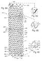
- FIGS. 6A-6E illustrate another stent 40.
- adjacent hoops 42a ... 42N are interdigitated with respect to one another. That is, oppositely directed apex sections 44A and 44B in respective adjacent hoops 42b and 42c, for example, overlap one another axially, or expressed another way, they intersect a common plane angularly disposed with respect to the axis of stent 40.
- Hoop members 42a ... 42N also preferably have zigs substantially in phase circumferentially about stent 40 .
- Stent 40 comprises a continuous series of similarly-oriented apex sections 44A arranged in a helix in which each hoop 42i comprises one 360-degree wrap of the helix.
- Each apex section in the helix comprises two struts attached thereto, in this embodiment with one strut being longer than the other to effect the helical progression.
- Such a hoop configuration is also seen in U.S. Patent No. 5,375,816 to Rudnick et al. , which illustrates a variety of other interdigitated stent configurations.
- one strut 45 of hoop member 42b is aligned with and overlaps strut 45 of hoop member 42c, and is connected to form a connecting member 48a-N, preferably by spot welding, although other connection mechanisms are contemplated as will be understood by those skilled in the art.
- Interdigitated stent 40 in its normal tubular form is illustrated in FIG. 6E .
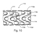
- Helical stent 110 corresponding to the layout shown in FIG 6A , on a tubular mandrel 114 .
- Each traversal of a preselected angular portion of mandrel 114 by pegs 112a-N includes at least one common peg ( 112r , for example) approximately 360° helically offset from an adjacent peg ( 112k ).
- the peg adjacent the common peg may be part of the same set of pegs (for instance, where N is equal to 1) or a part of a circumferentially adjoining set of pegs (where N is greater than 1).
- Common peg 112r provides at least one circumferential location in each traversal of a preselected angular portion, where a portion of the filament in each traversal of a preselected angular portion contacts a portion of a filament in an adjacent traversal.
- This contact may be with the same filament (for instance, where N is equal to 1 as shown in FIG. 11) or with an different filament (where N is greater than 1).
- a connection 48 is formed along the contacting adjacent filaments or portions thereof, forming a circumferential stent or segment thereof comprised of a helical succession of zig-zags.
- the wire configuration may form a helix as shown in FIGS. 6A , 6E , and 11, or a double- or other multiple-helix (not shown). As shown in FIG.
- a single filament (N 1) repeatedly traverses the mandrel (not shown) along a single set of pegs, wherein in each angular traversal of 450° there is a common peg 13' approximately (in this case slightly greater than) 360° offset from an adjacent peg 13' (the pegs immediately adjacent each connecting member 48a-N ).
- Stent 40 as shown in FIGS. 6A comprises a plurality of connecting members 48a-N disposed in succession along the stent axis between pairs of adjacent hoops.
- Each set of connecting members 48a-N connects a successive pair of adjacent hoops along the axis of stent 40 to form a spine along the length of the stent.
- each pair of successive connecting members 48 i is circumferentially offset from a preceding connecting member 48 i-1 with respect to the axis of stent 40.
- the zig including apex section 44B' has a greater included angle and has a greater zig width than the uniform angle and width included by apex sections 44B; apex section 44B" has a lesser included angle and smaller zig width than the uniform angle and width.
- stent 40 comprises a helical configuration having 4 zigs per 360-degree wrap, each such wrap comprising a hoop.
- Apex section 44B' is spaced 5 zigs from each preceding 44B'; apex section 44B" is similarly spaced 5 zigs from each preceding 44B".
- the non-uniform zigs are spaced every N+1 zigs to achieve the helical pattern of connections 48a-N as shown in Fig. 6A .
- connecting members 48a-N are uniformly distributed in a helical spacing approximately every 450° along the length of the stent to form a helical spine.
- Other helical or non-helical spine configurations may be achieved by spacing the non-uniform zigs differently.
- FIGS. 6B and 6C illustrate exemplary spot weld configurations within stent 40.
- the portion of each strut adjacent one another may be of a first length having a weld 54 of length L 1 , as shown in FIG. 6B .
- the portions of each strut adjacent one another may be longer, and thus may include a weld 56 of length L 2 , as shown in FIG. 6B .
- end strut 58 may be cut, as shown in FIG.
- FIG. 6D illustrates an exemplary radiopaque marker 59 that may be used with the present invention.
- Marker 59 may comprise a radiopaque substance, such as a platinum wire, wrapped about a strut on an end hoops. This substance thus defines a surface having a different radiopacity than the area surrounding it. This same effect may be achieved by marking a particular location of the stent with an area of lower radiopacity.
- One or more markers 59 may be disposed on one or both of the end hoops.
- Marker 59 generally may be tightly wound with no underlying strut visible to the unaided eye, and may extend 1-2 wraps past the start of the radius where the strut bends to form the apex section. Marker 59 is typically configured without sharp edges at the ends.
- FIG. 6F is a diagrammatic view of an exemplary stent 60 , opened along a line parallel to the stent axis and flattened, having interdigitated zigs, similar to stent 40 of FIG. 6A-E , but additionally having a plurality of longitudinal sections, similar to stent 10C as shown in FIG. 4 .
- Middle section 62 has a longer zig length than end sections 64, and transition sections 63 intermediate the middle section and each end section have a zig length that is between the length of the middle and the end section zigs.
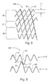
- FIG. 7 illustrates still another stent 70 .
- Stent 70 has been cut longitudinally and laid flat for purposes of illustration.
- Stent 70 is formed by winding a wire around pins extending from a mandrel somewhat similar to the manner described with reference to FIG. 1 , although the pins are configured such that zig-zag sections of respective hoops 76a, 76b, 76c, 76d are of varying height and varying width.
- the width of the zig length alternates between distance XX and WW along each hoop circumferentially about stent 70.
- the zig length similarly alternates between length YY and ZZ moving along each hoop circumferentially about stent 70.
- Length ZZ is approximately half of length YY in FIG. 7 , although other length variations are contemplated.
- Adjacent hoops, such as hoops 76a and 76b, are phase-shifted by approximately and 180 degrees and inverted with respect to one another. Accordingly, apex sections 65 and 66 of hoop member 76a pass through a plane perpendicular to the axis of stent 60 determined by the positions of oppositely directed alternate apex sections 67 and 68 in adjacent hoop 76b.
- the configuration of FIG. 7 may be incorporated into transition segments of other stents constructed according to the present invention.
- a series of separate bridging members 72a, 72b, and 72c connects adjacent hoops 76a and 76b, as shown in Fig. 7 .
- Another series of separate connecting members 74a and 74b connects adjacent hoops 62b and 62c.
- Bridging members 72a, 72b, and 72c are angled relative to the tubular axis of stent 70 in opposite orientations than bridging members 74a and 74b, to counter rotating effects in stents in which bridging members between successive pairs of adjacent hoops are oriented in the same direction.
- the number of bridging members may vary, depending on the desired implementation, as may the orientations of bridging members 72a, 72b, 72c, 74a and 74b.
- the stent may comprise a plurality of longitudinal sections, each of which may differ from another segment with respect to, for example without limitation: the size of one or more of the apex section angle, the apex section axial length, the number of apex sections per hoop, the number of connective spines, the spacing or offset between facing apex sections, the type of connecting member, and the uniformity of adjacent zigs.
- the "struts" of each apex section and the connections therebetween may be straight, as in a jagged zig-zag configuration, or curved somewhat, such as when the overall stent section is more sinusoidal.
Applications Claiming Priority (2)
| Application Number | Priority Date | Filing Date | Title |
|---|---|---|---|
| US7694698P | 1998-03-05 | 1998-03-05 | |
| EP99909791A EP1065993B1 (en) | 1998-03-05 | 1999-03-04 | Intraluminal stent |
Related Parent Applications (1)
| Application Number | Title | Priority Date | Filing Date |
|---|---|---|---|
| EP99909791.8 Division | 1999-03-04 |
Publications (3)
| Publication Number | Publication Date |
|---|---|
| EP2277477A2 EP2277477A2 (en) | 2011-01-26 |
| EP2277477A3 EP2277477A3 (en) | 2011-03-02 |
| EP2277477B1 true EP2277477B1 (en) | 2012-05-09 |
Family
ID=22135152
Family Applications (3)
| Application Number | Title | Priority Date | Filing Date |
|---|---|---|---|
| EP10172426A Expired - Lifetime EP2277477B1 (en) | 1998-03-05 | 1999-03-04 | Intraluminal stent |
| EP99909791A Expired - Lifetime EP1065993B1 (en) | 1998-03-05 | 1999-03-04 | Intraluminal stent |
| EP09172655A Expired - Lifetime EP2198813B1 (en) | 1998-03-05 | 1999-03-04 | Intraluminal stent |
Family Applications After (2)
| Application Number | Title | Priority Date | Filing Date |
|---|---|---|---|
| EP99909791A Expired - Lifetime EP1065993B1 (en) | 1998-03-05 | 1999-03-04 | Intraluminal stent |
| EP09172655A Expired - Lifetime EP2198813B1 (en) | 1998-03-05 | 1999-03-04 | Intraluminal stent |
Country Status (7)
| Country | Link |
|---|---|
| US (4) | US6730117B1 (ja) |
| EP (3) | EP2277477B1 (ja) |
| JP (2) | JP4801838B2 (ja) |
| AU (1) | AU2891899A (ja) |
| CA (1) | CA2322973C (ja) |
| DE (1) | DE69942666D1 (ja) |
| WO (1) | WO1999044535A1 (ja) |
Families Citing this family (130)
| Publication number | Priority date | Publication date | Assignee | Title |
|---|---|---|---|---|
| US7204848B1 (en) | 1995-03-01 | 2007-04-17 | Boston Scientific Scimed, Inc. | Longitudinally flexible expandable stent |
| US6896696B2 (en) | 1998-11-20 | 2005-05-24 | Scimed Life Systems, Inc. | Flexible and expandable stent |
| EP0884029B1 (en) * | 1997-06-13 | 2004-12-22 | Gary J. Becker | Expandable intraluminal endoprosthesis |
| JP4801838B2 (ja) * | 1998-03-05 | 2011-10-26 | ボストン サイエンティフィック リミテッド | 腔内ステント |
| US6261319B1 (en) | 1998-07-08 | 2001-07-17 | Scimed Life Systems, Inc. | Stent |
| US20040267349A1 (en) | 2003-06-27 | 2004-12-30 | Kobi Richter | Amorphous metal alloy medical devices |
| US8382821B2 (en) | 1998-12-03 | 2013-02-26 | Medinol Ltd. | Helical hybrid stent |
| ATE311833T1 (de) * | 1999-02-01 | 2005-12-15 | Univ Texas | Gewebte intravaskuläre vorrichtung und verfahren zur herstellung |
| US7018401B1 (en) | 1999-02-01 | 2006-03-28 | Board Of Regents, The University Of Texas System | Woven intravascular devices and methods for making the same and apparatus for delivery of the same |
| US6544279B1 (en) * | 2000-08-09 | 2003-04-08 | Incept, Llc | Vascular device for emboli, thrombus and foreign body removal and methods of use |
| US6302907B1 (en) * | 1999-10-05 | 2001-10-16 | Scimed Life Systems, Inc. | Flexible endoluminal stent and process of manufacture |
| US6585758B1 (en) | 1999-11-16 | 2003-07-01 | Scimed Life Systems, Inc. | Multi-section filamentary endoluminal stent |
| US6610087B1 (en) | 1999-11-16 | 2003-08-26 | Scimed Life Systems, Inc. | Endoluminal stent having a matched stiffness region and/or a stiffness gradient and methods for providing stent kink resistance |
| US20020072792A1 (en) * | 2000-09-22 | 2002-06-13 | Robert Burgermeister | Stent with optimal strength and radiopacity characteristics |
| EP2311411B1 (en) | 2000-12-11 | 2015-09-23 | OrbusNeich Medical, Inc. | Stent having helical elements |
| US8038708B2 (en) | 2001-02-05 | 2011-10-18 | Cook Medical Technologies Llc | Implantable device with remodelable material and covering material |
| DE10118944B4 (de) * | 2001-04-18 | 2013-01-31 | Merit Medical Systems, Inc. | Entfernbare, im wesentlichen zylindrische Implantate |
| US6746466B2 (en) | 2001-05-22 | 2004-06-08 | Scimed Life Systems, Inc. | Method and apparatus for managing multiple guidewires |
| US7727221B2 (en) | 2001-06-27 | 2010-06-01 | Cardiac Pacemakers Inc. | Method and device for electrochemical formation of therapeutic species in vivo |
| US7163553B2 (en) * | 2001-12-28 | 2007-01-16 | Advanced Cardiovascular Systems, Inc. | Intravascular stent and method of use |
| US20030187495A1 (en) | 2002-04-01 | 2003-10-02 | Cully Edward H. | Endoluminal devices, embolic filters, methods of manufacture and use |
| US6865810B2 (en) * | 2002-06-27 | 2005-03-15 | Scimed Life Systems, Inc. | Methods of making medical devices |
| DE10243136A1 (de) * | 2002-09-17 | 2004-05-19 | Campus Medizin & Technik Gmbh | Stent zur Implantation in oder um ein Hohlorgan |
| US20040093012A1 (en) * | 2002-10-17 | 2004-05-13 | Cully Edward H. | Embolic filter frame having looped support strut elements |
| US20040093056A1 (en) | 2002-10-26 | 2004-05-13 | Johnson Lianw M. | Medical appliance delivery apparatus and method of use |
| US7959671B2 (en) | 2002-11-05 | 2011-06-14 | Merit Medical Systems, Inc. | Differential covering and coating methods |
| US7637942B2 (en) | 2002-11-05 | 2009-12-29 | Merit Medical Systems, Inc. | Coated stent with geometry determinated functionality and method of making the same |
| US7875068B2 (en) | 2002-11-05 | 2011-01-25 | Merit Medical Systems, Inc. | Removable biliary stent |
| US6916409B1 (en) * | 2002-12-31 | 2005-07-12 | Advanced Cardiovascular Systems, Inc. | Apparatus and process for electrolytic removal of material from a medical device |
| US7637934B2 (en) | 2003-03-31 | 2009-12-29 | Merit Medical Systems, Inc. | Medical appliance optical delivery and deployment apparatus and method |
| US7717952B2 (en) * | 2003-04-24 | 2010-05-18 | Cook Incorporated | Artificial prostheses with preferred geometries |
| US7658759B2 (en) * | 2003-04-24 | 2010-02-09 | Cook Incorporated | Intralumenally implantable frames |
| US7625399B2 (en) * | 2003-04-24 | 2009-12-01 | Cook Incorporated | Intralumenally-implantable frames |
| DE602004023708D1 (de) | 2003-04-24 | 2009-12-03 | Cook Inc | Künstliche klappe für blutgefäss mit verbessertem fliessverhalten |
| US7604660B2 (en) | 2003-05-01 | 2009-10-20 | Merit Medical Systems, Inc. | Bifurcated medical appliance delivery apparatus and method |
| US9155639B2 (en) | 2009-04-22 | 2015-10-13 | Medinol Ltd. | Helical hybrid stent |
| US9039755B2 (en) * | 2003-06-27 | 2015-05-26 | Medinol Ltd. | Helical hybrid stent |
| US7344559B2 (en) * | 2003-08-25 | 2008-03-18 | Biophan Technologies, Inc. | Electromagnetic radiation transparent device and method of making thereof |
| WO2006024490A2 (en) | 2004-08-30 | 2006-03-09 | Interstitial Therapeutics | Methods and compositions for the treatment of cell proliferation |
| WO2006036912A2 (en) * | 2004-09-27 | 2006-04-06 | Echobio Llc | Systems, apparatus and methods related to helical, non-helical or removable stents with rectilinear ends |
| US7887579B2 (en) * | 2004-09-29 | 2011-02-15 | Merit Medical Systems, Inc. | Active stent |
| WO2006051912A1 (ja) * | 2004-11-12 | 2006-05-18 | Kabushikikaisha Igaki Iryo Sekkei | 脈管用ステント |
| ES2764992T3 (es) | 2005-04-04 | 2020-06-05 | Flexible Stenting Solutions Inc | Stent flexible |
| US20060237407A1 (en) * | 2005-04-25 | 2006-10-26 | Nguyen Anh V | Medical devices having laser brazed joints |
| US7731654B2 (en) | 2005-05-13 | 2010-06-08 | Merit Medical Systems, Inc. | Delivery device with viewing window and associated method |
| US7637939B2 (en) * | 2005-06-30 | 2009-12-29 | Boston Scientific Scimed, Inc. | Hybrid stent |
| DE102006017873A1 (de) * | 2005-07-14 | 2007-01-25 | Qualimed Innovative Medizinprodukte Gmbh | Temporärer Stent |
| KR100633020B1 (ko) * | 2005-07-15 | 2006-10-11 | 주식회사 스텐다드싸이텍 | 스텐트 및 그의 제작 방법 |
| DE102005037863B4 (de) | 2005-08-10 | 2018-10-18 | Carlo Civelli | Rohrförmige Stützprothese mit sich seitlich überlappenden Krümmungsbögen |
| US8956400B2 (en) * | 2005-10-14 | 2015-02-17 | Flexible Stenting Solutions, Inc. | Helical stent |
| CA2857815C (en) * | 2005-12-30 | 2016-10-11 | C.R. Bard Inc. | Stent with bio-resorbable connector and methods |
| US8840660B2 (en) | 2006-01-05 | 2014-09-23 | Boston Scientific Scimed, Inc. | Bioerodible endoprostheses and methods of making the same |
| KR100664531B1 (ko) * | 2006-01-26 | 2007-01-04 | (주) 태웅메디칼 | 형상기억합급을 이용한 가변상태 유지형 확장기구의제조방법과 이에 의해 제조된 확장기구 |
| US8089029B2 (en) | 2006-02-01 | 2012-01-03 | Boston Scientific Scimed, Inc. | Bioabsorbable metal medical device and method of manufacture |
| US9615832B2 (en) * | 2006-04-07 | 2017-04-11 | Penumbra, Inc. | Aneurysm occlusion system and method |
| US8048150B2 (en) | 2006-04-12 | 2011-11-01 | Boston Scientific Scimed, Inc. | Endoprosthesis having a fiber meshwork disposed thereon |
| US20110230958A1 (en) * | 2006-07-25 | 2011-09-22 | Mani, Inc. | Stent |
| US8052743B2 (en) | 2006-08-02 | 2011-11-08 | Boston Scientific Scimed, Inc. | Endoprosthesis with three-dimensional disintegration control |
| US20080071353A1 (en) * | 2006-09-15 | 2008-03-20 | Boston Scientific Scimed, Inc. | Endoprosthesis containing magnetic induction particles |
| ES2357661T3 (es) | 2006-09-15 | 2011-04-28 | Boston Scientific Scimed, Inc. | Endoprótesis bioerosionables con capas inorgánicas bioestables. |
| WO2008034013A2 (en) | 2006-09-15 | 2008-03-20 | Boston Scientific Limited | Medical devices and methods of making the same |
| US8057534B2 (en) | 2006-09-15 | 2011-11-15 | Boston Scientific Scimed, Inc. | Bioerodible endoprostheses and methods of making the same |
| CA2663250A1 (en) | 2006-09-15 | 2008-03-20 | Boston Scientific Limited | Bioerodible endoprostheses and methods of making the same |
| CA2663198A1 (en) * | 2006-09-15 | 2008-03-20 | Boston Scientific Limited | Medical devices |
| JP5455633B2 (ja) | 2006-10-22 | 2014-03-26 | アイデブ テクノロジーズ インコーポレイテッド | ステント前進のためのデバイスおよび方法 |
| US9895242B2 (en) | 2006-10-22 | 2018-02-20 | Idev Technologies, Inc. | Secured strand end devices |
| US9622888B2 (en) | 2006-11-16 | 2017-04-18 | W. L. Gore & Associates, Inc. | Stent having flexibly connected adjacent stent elements |
| US8768486B2 (en) | 2006-12-11 | 2014-07-01 | Medtronic, Inc. | Medical leads with frequency independent magnetic resonance imaging protection |
| ES2506144T3 (es) | 2006-12-28 | 2014-10-13 | Boston Scientific Limited | Endoprótesis bioerosionables y procedimiento de fabricación de las mismas |
| US7758635B2 (en) * | 2007-02-13 | 2010-07-20 | Boston Scientific Scimed, Inc. | Medical device including cylindrical micelles |
| US20080319535A1 (en) * | 2007-06-25 | 2008-12-25 | Medtronic Vascular, Inc. | Vascular Stent and Method of Making Vascular Stent |
| US7988723B2 (en) | 2007-08-02 | 2011-08-02 | Flexible Stenting Solutions, Inc. | Flexible stent |
| US8052745B2 (en) | 2007-09-13 | 2011-11-08 | Boston Scientific Scimed, Inc. | Endoprosthesis |
| US8926688B2 (en) | 2008-01-11 | 2015-01-06 | W. L. Gore & Assoc. Inc. | Stent having adjacent elements connected by flexible webs |
| US8042251B2 (en) * | 2008-05-21 | 2011-10-25 | Boston Scientific Scimed, Inc. | Systems and methods for heating and cooling during stent crimping |
| US8236046B2 (en) * | 2008-06-10 | 2012-08-07 | Boston Scientific Scimed, Inc. | Bioerodible endoprosthesis |
| WO2009157164A1 (ja) | 2008-06-27 | 2009-12-30 | 株式会社 京都医療設計 | 脈管用ステント |
| US8109985B2 (en) | 2008-07-23 | 2012-02-07 | Boston Scientific Scimed, Inc. | Occlusion crossing device and method |
| US7985252B2 (en) | 2008-07-30 | 2011-07-26 | Boston Scientific Scimed, Inc. | Bioerodible endoprosthesis |
| US8382824B2 (en) | 2008-10-03 | 2013-02-26 | Boston Scientific Scimed, Inc. | Medical implant having NANO-crystal grains with barrier layers of metal nitrides or fluorides |
| US9149376B2 (en) | 2008-10-06 | 2015-10-06 | Cordis Corporation | Reconstrainable stent delivery system |
| KR101678372B1 (ko) * | 2009-02-02 | 2016-12-06 | 코디스 코포레이션 | 가요성 스텐트 디자인 |
| EP2403546A2 (en) | 2009-03-02 | 2012-01-11 | Boston Scientific Scimed, Inc. | Self-buffering medical implants |
| GB2472603B (en) * | 2009-08-11 | 2011-12-14 | Cook Medical Technologies Llc | Implantable medical device |
| US9060889B2 (en) * | 2009-09-18 | 2015-06-23 | Medtronic Vascular, Inc. | Methods for forming an orthogonal end on a helical stent |
| WO2011064782A2 (en) | 2009-11-30 | 2011-06-03 | Endospan Ltd. | Multi-component stent-graft system for implantation in a blood vessel with multiple branches |
| DE102010008362A1 (de) * | 2010-02-17 | 2011-08-18 | Transcatheter Technologies GmbH, 93053 | Medizinisches Implantat, welches aus einem nicht expandierten Zustand expandierbar ist |
| US20110218615A1 (en) * | 2010-03-02 | 2011-09-08 | Medtronic Vascular, Inc. | Stent With Multi-Crown Constraint and Method for Ending Helical Wound Stents |
| US8206434B2 (en) | 2010-03-02 | 2012-06-26 | Medtronic Vascular, Inc. | Stent with sinusoidal wave form and orthogonal end and method for making same |
| US8668732B2 (en) | 2010-03-23 | 2014-03-11 | Boston Scientific Scimed, Inc. | Surface treated bioerodible metal endoprostheses |
| US9023095B2 (en) | 2010-05-27 | 2015-05-05 | Idev Technologies, Inc. | Stent delivery system with pusher assembly |
| US8328072B2 (en) | 2010-07-19 | 2012-12-11 | Medtronic Vascular, Inc. | Method for forming a wave form used to make wound stents |
| EP2658484A1 (en) | 2010-12-30 | 2013-11-06 | Boston Scientific Scimed, Inc. | Multi stage opening stent designs |
| US9526638B2 (en) | 2011-02-03 | 2016-12-27 | Endospan Ltd. | Implantable medical devices constructed of shape memory material |
| GB2488165B (en) * | 2011-02-18 | 2013-08-07 | Cook Medical Technologies Llc | Prosthesis and method of manufacturing the same |
| US9486341B2 (en) | 2011-03-02 | 2016-11-08 | Endospan Ltd. | Reduced-strain extra-vascular ring for treating aortic aneurysm |
| US8790388B2 (en) | 2011-03-03 | 2014-07-29 | Boston Scientific Scimed, Inc. | Stent with reduced profile |
| CN103391757B (zh) | 2011-03-03 | 2016-01-20 | 波士顿科学国际有限公司 | 低应变高强度支架 |
| EP3275402B1 (en) * | 2011-03-17 | 2021-08-25 | PQ Bypass, Inc. | Differential dilation stent |
| US8840659B2 (en) | 2011-04-28 | 2014-09-23 | Cook Medical Technologies Llc | Stent and stent-graft designs |
| WO2013005207A1 (en) | 2011-07-07 | 2013-01-10 | Endospan Ltd. | Stent fixation with reduced plastic deformation |
| US9296034B2 (en) | 2011-07-26 | 2016-03-29 | Medtronic Vascular, Inc. | Apparatus and method for forming a wave form for a stent from a wire |
| WO2013030818A2 (en) * | 2011-08-28 | 2013-03-07 | Endospan Ltd. | Stent-grafts with post-deployment variable axial and radial displacement |
| US10940167B2 (en) | 2012-02-10 | 2021-03-09 | Cvdevices, Llc | Methods and uses of biological tissues for various stent and other medical applications |
| US9636241B2 (en) * | 2012-03-30 | 2017-05-02 | Manli International Ltd | Coil bioabsorbable stents |
| US9242290B2 (en) | 2012-04-03 | 2016-01-26 | Medtronic Vascular, Inc. | Method and apparatus for creating formed elements used to make wound stents |
| US9238260B2 (en) | 2012-04-18 | 2016-01-19 | Medtronic Vascular, Inc. | Method and apparatus for creating formed elements used to make wound stents |
| US9364351B2 (en) * | 2012-04-23 | 2016-06-14 | Medtronic Vascular, Inc. | Method for forming a stent |
| EP3957276A1 (en) | 2012-05-31 | 2022-02-23 | Javelin Medical Ltd. | Device for embolic protection |
| US9308007B2 (en) | 2012-08-14 | 2016-04-12 | W. L. Gore & Associates, Inc. | Devices and systems for thrombus treatment |
| US9993360B2 (en) | 2013-01-08 | 2018-06-12 | Endospan Ltd. | Minimization of stent-graft migration during implantation |
| CN107028679A (zh) | 2013-01-18 | 2017-08-11 | 标枪医疗有限公司 | 单丝植入物和用于递送单丝植入物的系统 |
| AU2014214700B2 (en) | 2013-02-11 | 2018-01-18 | Cook Medical Technologies Llc | Expandable support frame and medical device |
| CN105208969B (zh) | 2013-03-11 | 2017-10-20 | 恩多斯潘有限公司 | 用于主动脉夹层的多组件支架移植物系统 |
| CN105722480A (zh) | 2013-06-20 | 2016-06-29 | 生物传感器国际集团有限公司 | 具有混合构型的连接体的血管支架 |
| CN105611901B (zh) * | 2013-08-09 | 2017-09-08 | 波士顿科学国际有限公司 | 支架设计及制造方法 |
| US10603197B2 (en) | 2013-11-19 | 2020-03-31 | Endospan Ltd. | Stent system with radial-expansion locking |
| US9592110B1 (en) | 2013-12-06 | 2017-03-14 | Javelin Medical, Ltd. | Systems and methods for implant delivery |
| KR101488972B1 (ko) * | 2014-09-12 | 2015-02-02 | (주)시지바이오 | 스텐트 및 이 스텐트의 제조방법 |
| US10299948B2 (en) | 2014-11-26 | 2019-05-28 | W. L. Gore & Associates, Inc. | Balloon expandable endoprosthesis |
| BR112017012425A2 (pt) | 2014-12-18 | 2018-01-02 | Endospan Ltd | enxerto por stent endovascular com tubo lateral resistente à fadiga |
| EP3435929B1 (en) * | 2016-03-29 | 2020-05-20 | Cardinal Health Switzerland 515 GmbH | Contracting stent with bioresorbable struts |
| US10568752B2 (en) | 2016-05-25 | 2020-02-25 | W. L. Gore & Associates, Inc. | Controlled endoprosthesis balloon expansion |
| CN106725643A (zh) * | 2016-06-22 | 2017-05-31 | 苏州茵络医疗器械有限公司 | 用于血管腔内手术的破膜器 |
| EP3528712B1 (en) | 2016-10-21 | 2023-10-18 | Javelin Medical Ltd. | Devices for embolic protection |
| US11224910B2 (en) | 2017-03-03 | 2022-01-18 | Cook Medical Technologies Llc | Method of forming a bend of a predetermined bend angle in a shape memory alloy wire and method of making a self-expanding stent |
| US11464998B2 (en) | 2019-02-14 | 2022-10-11 | Videra Surgical Inc. | Fiducial marker for oncological and other procedures |
| US11517457B2 (en) * | 2019-07-03 | 2022-12-06 | Abbott Cardiovascular Systems Inc. | Intravascular stent |
| CN112972083B (zh) * | 2019-12-17 | 2022-11-11 | 北京迈迪顶峰医疗科技股份有限公司 | 幼儿肺动脉支架 |
| KR102438975B1 (ko) * | 2020-08-12 | 2022-09-01 | 주식회사 에스앤지바이오텍 | 이중 구조 스텐트 및 그 제조 방법 |
Family Cites Families (83)
| Publication number | Priority date | Publication date | Assignee | Title |
|---|---|---|---|---|
| US4512338A (en) | 1983-01-25 | 1985-04-23 | Balko Alexander B | Process for restoring patency to body vessels |
| US5102417A (en) | 1985-11-07 | 1992-04-07 | Expandable Grafts Partnership | Expandable intraluminal graft, and method and apparatus for implanting an expandable intraluminal graft |
| EP0380668B1 (en) | 1987-10-08 | 1996-12-27 | Terumo Kabushiki Kaisha | Instrument and apparatus for securing inner diameter of lumen of tubular organ |
| US5133732A (en) | 1987-10-19 | 1992-07-28 | Medtronic, Inc. | Intravascular stent |
| US4886062A (en) | 1987-10-19 | 1989-12-12 | Medtronic, Inc. | Intravascular radially expandable stent and method of implant |
| US5019090A (en) | 1988-09-01 | 1991-05-28 | Corvita Corporation | Radially expandable endoprosthesis and the like |
| CA1322628C (en) | 1988-10-04 | 1993-10-05 | Richard A. Schatz | Expandable intraluminal graft |
| US4856516A (en) | 1989-01-09 | 1989-08-15 | Cordis Corporation | Endovascular stent apparatus and method |
| US4994071A (en) | 1989-05-22 | 1991-02-19 | Cordis Corporation | Bifurcating stent apparatus and method |
| US5292331A (en) | 1989-08-24 | 1994-03-08 | Applied Vascular Engineering, Inc. | Endovascular support device |
| US5674278A (en) | 1989-08-24 | 1997-10-07 | Arterial Vascular Engineering, Inc. | Endovascular support device |
| CA2026604A1 (en) | 1989-10-02 | 1991-04-03 | Rodney G. Wolff | Articulated stent |
| US5035706A (en) | 1989-10-17 | 1991-07-30 | Cook Incorporated | Percutaneous stent and method for retrieval thereof |
| ATE135555T1 (de) | 1990-10-09 | 1996-04-15 | Cook Inc | Perkutane stentanordnung |
| US5217483A (en) | 1990-11-28 | 1993-06-08 | Numed, Inc. | Intravascular radially expandable stent |
| US5135536A (en) | 1991-02-05 | 1992-08-04 | Cordis Corporation | Endovascular stent and method |
| US5314472A (en) * | 1991-10-01 | 1994-05-24 | Cook Incorporated | Vascular stent |
| US5443498A (en) | 1991-10-01 | 1995-08-22 | Cook Incorporated | Vascular stent and method of making and implanting a vacsular stent |
| US5354309A (en) | 1991-10-11 | 1994-10-11 | Angiomed Ag | Apparatus for widening a stenosis in a body cavity |
| CA2079417C (en) | 1991-10-28 | 2003-01-07 | Lilip Lau | Expandable stents and method of making same |
| US5507767A (en) | 1992-01-15 | 1996-04-16 | Cook Incorporated | Spiral stent |
| US5486193A (en) | 1992-01-22 | 1996-01-23 | C. R. Bard, Inc. | System for the percutaneous transluminal front-end loading delivery of a prosthetic occluder |
| US5405377A (en) | 1992-02-21 | 1995-04-11 | Endotech Ltd. | Intraluminal stent |
| US5282823A (en) * | 1992-03-19 | 1994-02-01 | Medtronic, Inc. | Intravascular radially expandable stent |
| US5370683A (en) | 1992-03-25 | 1994-12-06 | Cook Incorporated | Vascular stent |
| US6336938B1 (en) * | 1992-08-06 | 2002-01-08 | William Cook Europe A/S | Implantable self expanding prosthetic device |
| DK0653924T3 (da) * | 1992-08-06 | 1997-07-14 | Cook William Europ | proteseindretning til at opretholde lumen i et kar eller et hult organ. |
| BE1006440A3 (fr) * | 1992-12-21 | 1994-08-30 | Dereume Jean Pierre Georges Em | Endoprothese luminale et son procede de preparation. |
| DE4303181A1 (de) * | 1993-02-04 | 1994-08-11 | Angiomed Ag | Implantierbarer Katheter |
| GB2281865B (en) | 1993-09-16 | 1997-07-30 | Cordis Corp | Endoprosthesis having multiple laser welded junctions,method and procedure |
| US5913897A (en) * | 1993-09-16 | 1999-06-22 | Cordis Corporation | Endoprosthesis having multiple bridging junctions and procedure |
| JP2703510B2 (ja) | 1993-12-28 | 1998-01-26 | アドヴァンスド カーディオヴァスキュラー システムズ インコーポレーテッド | 拡大可能なステント及びその製造方法 |
| US5609627A (en) | 1994-02-09 | 1997-03-11 | Boston Scientific Technology, Inc. | Method for delivering a bifurcated endoluminal prosthesis |
| US5549663A (en) | 1994-03-09 | 1996-08-27 | Cordis Corporation | Endoprosthesis having graft member and exposed welded end junctions, method and procedure |
| US5449373A (en) | 1994-03-17 | 1995-09-12 | Medinol Ltd. | Articulated stent |
| US6165210A (en) | 1994-04-01 | 2000-12-26 | Gore Enterprise Holdings, Inc. | Self-expandable helical intravascular stent and stent-graft |
| EP0858298A4 (en) * | 1994-04-29 | 1999-04-07 | Boston Scient Corp | MEDICAL STENT PROSTHESIS AND METHOD FOR THE PRODUCTION |
| EP0688545B1 (en) * | 1994-06-17 | 2002-09-18 | Terumo Kabushiki Kaisha | Method for manufacturing an indwelling stent |
| US5575816A (en) | 1994-08-12 | 1996-11-19 | Meadox Medicals, Inc. | High strength and high density intraluminal wire stent |
| US5891108A (en) * | 1994-09-12 | 1999-04-06 | Cordis Corporation | Drug delivery stent |
| NL9500283A (nl) * | 1994-10-21 | 1996-06-03 | Cordis Europ | Catheter met leiddraadkanaal. |
| US6818014B2 (en) | 1995-03-01 | 2004-11-16 | Scimed Life Systems, Inc. | Longitudinally flexible expandable stent |
| DE69637527D1 (de) | 1995-03-01 | 2008-06-26 | Boston Scient Scimed Inc | Längsflexibler und expandierbarer stent |
| ATE169484T1 (de) * | 1995-04-01 | 1998-08-15 | Variomed Ag | Stent zur transluminalen implantation in hohlorgane |
| JPH10501491A (ja) * | 1995-04-12 | 1998-02-10 | イーストマン コダック カンパニー | 液体インク印刷装置およびシステム |
| US5667523A (en) * | 1995-04-28 | 1997-09-16 | Impra, Inc. | Dual supported intraluminal graft |
| DE69630030T2 (de) * | 1995-06-08 | 2004-06-09 | Ave Galway Ltd. | Endovaskularer stent |
| FR2735016B1 (fr) * | 1995-06-09 | 1997-12-12 | Sgro Jean Claude | Implant endo-luminal |
| FR2737404B1 (fr) * | 1995-08-03 | 1997-09-19 | Braun Celsa Sa | Prothese implantable dans un conduit humain ou animal, telle qu'un elargisseur de paroi, ou une prothese pour anevrisme |
| DK171865B1 (da) | 1995-09-11 | 1997-07-21 | Cook William Europ | Ekspanderbar endovasculær stent |
| WO1997014375A1 (en) | 1995-10-20 | 1997-04-24 | Bandula Wijay | Vascular stent |
| US5843158A (en) * | 1996-01-05 | 1998-12-01 | Medtronic, Inc. | Limited expansion endoluminal prostheses and methods for their use |
| US5895406A (en) * | 1996-01-26 | 1999-04-20 | Cordis Corporation | Axially flexible stent |
| DE69729137T2 (de) * | 1996-03-10 | 2005-05-12 | Terumo K.K. | Stent zur Implantation |
| CA2199890C (en) | 1996-03-26 | 2002-02-05 | Leonard Pinchuk | Stents and stent-grafts having enhanced hoop strength and methods of making the same |
| EP0801934B1 (en) * | 1996-04-16 | 2000-06-14 | Medtronic, Inc. | Welded sinusoidal wave stent |
| FR2750852B3 (fr) * | 1996-07-10 | 1998-08-07 | Braun Celsa Sa | Prothese medicale a meandres comprenant des moyens de retenue de ses apex |
| FR2750853B1 (fr) | 1996-07-10 | 1998-12-18 | Braun Celsa Sa | Prothese medicale, en particulier pour anevrismes, a liaison perfectionnee entre sa gaine et sa structure |
| US6174326B1 (en) * | 1996-09-25 | 2001-01-16 | Terumo Kabushiki Kaisha | Radiopaque, antithrombogenic stent and method for its production |
| BR9706814A (pt) * | 1996-10-01 | 1999-12-28 | Numed Inc | Dispositivo tipo stent radialmente expansìvel. |
| US6530951B1 (en) * | 1996-10-24 | 2003-03-11 | Cook Incorporated | Silver implantable medical device |
| WO1998020810A1 (en) | 1996-11-12 | 1998-05-22 | Medtronic, Inc. | Flexible, radially expansible luminal prostheses |
| US6551350B1 (en) | 1996-12-23 | 2003-04-22 | Gore Enterprise Holdings, Inc. | Kink resistant bifurcated prosthesis |
| US5925061A (en) | 1997-01-13 | 1999-07-20 | Gore Enterprise Holdings, Inc. | Low profile vascular stent |
| US5911732A (en) * | 1997-03-10 | 1999-06-15 | Johnson & Johnson Interventional Systems, Co. | Articulated expandable intraluminal stent |
| US5810872A (en) * | 1997-03-14 | 1998-09-22 | Kanesaka; Nozomu | Flexible stent |
| US5855597A (en) * | 1997-05-07 | 1999-01-05 | Iowa-India Investments Co. Limited | Stent valve and stent graft for percutaneous surgery |
| EP0890346A1 (en) * | 1997-06-13 | 1999-01-13 | Gary J. Becker | Expandable intraluminal endoprosthesis |
| US5948016A (en) * | 1997-09-25 | 1999-09-07 | Jang; G. David | Intravascular stent with non-parallel slots |
| US6200334B1 (en) * | 1998-02-03 | 2001-03-13 | G. David Jang | Tubular stent consists of non-parallel expansion struts and contralaterally attached diagonal connectors |
| JP4801838B2 (ja) * | 1998-03-05 | 2011-10-26 | ボストン サイエンティフィック リミテッド | 腔内ステント |
| US6132460A (en) * | 1998-03-27 | 2000-10-17 | Intratherapeutics, Inc. | Stent |
| US6558415B2 (en) * | 1998-03-27 | 2003-05-06 | Intratherapeutics, Inc. | Stent |
| US6042597A (en) * | 1998-10-23 | 2000-03-28 | Scimed Life Systems, Inc. | Helical stent design |
| US6368346B1 (en) * | 1999-06-03 | 2002-04-09 | American Medical Systems, Inc. | Bioresorbable stent |
| US6364904B1 (en) * | 1999-07-02 | 2002-04-02 | Scimed Life Systems, Inc. | Helically formed stent/graft assembly |
| FR2799363B1 (fr) | 1999-10-11 | 2001-11-30 | Braun Celsa Sa | Implant medical a meandres en zigzag |
| US6331189B1 (en) * | 1999-10-18 | 2001-12-18 | Medtronic, Inc. | Flexible medical stent |
| US6423091B1 (en) * | 2000-05-16 | 2002-07-23 | Cordis Corporation | Helical stent having flat ends |
| EP1284683B1 (en) | 2000-05-22 | 2011-08-10 | OrbusNeich Medical, Inc. | Self-expanding stent |
| US7279003B2 (en) * | 2003-04-24 | 2007-10-09 | Medtronic Vascular, Inc. | Stent graft tapered spring |
| WO2006005026A2 (en) | 2004-06-30 | 2006-01-12 | Cordis Corporation | Stent having asymetrical members of unequal length |
| US7404823B2 (en) * | 2005-10-31 | 2008-07-29 | Boston Scientific Scimed, Inc. | Stent configurations |
-
1999
- 1999-03-04 JP JP2000534143A patent/JP4801838B2/ja not_active Expired - Lifetime
- 1999-03-04 US US09/623,347 patent/US6730117B1/en not_active Expired - Lifetime
- 1999-03-04 EP EP10172426A patent/EP2277477B1/en not_active Expired - Lifetime
- 1999-03-04 WO PCT/US1999/004694 patent/WO1999044535A1/en active Application Filing
- 1999-03-04 EP EP99909791A patent/EP1065993B1/en not_active Expired - Lifetime
- 1999-03-04 EP EP09172655A patent/EP2198813B1/en not_active Expired - Lifetime
- 1999-03-04 CA CA2322973A patent/CA2322973C/en not_active Expired - Fee Related
- 1999-03-04 DE DE69942666T patent/DE69942666D1/de not_active Expired - Lifetime
- 1999-03-04 AU AU28918/99A patent/AU2891899A/en not_active Abandoned
-
2003
- 2003-12-29 US US10/747,848 patent/US8118858B2/en not_active Expired - Fee Related
-
2010
- 2010-04-08 JP JP2010089909A patent/JP2010155120A/ja not_active Withdrawn
- 2010-09-23 US US12/888,810 patent/US20110015721A1/en not_active Abandoned
-
2013
- 2013-02-28 US US13/780,833 patent/US8764815B2/en not_active Expired - Fee Related
Also Published As
| Publication number | Publication date |
|---|---|
| WO1999044535A8 (en) | 2001-11-01 |
| DE69942666D1 (de) | 2010-09-23 |
| EP2277477A2 (en) | 2011-01-26 |
| AU2891899A (en) | 1999-09-20 |
| US20130178948A1 (en) | 2013-07-11 |
| US20040143318A1 (en) | 2004-07-22 |
| EP1065993B1 (en) | 2010-08-11 |
| JP4801838B2 (ja) | 2011-10-26 |
| US6730117B1 (en) | 2004-05-04 |
| EP2198813B1 (en) | 2012-08-29 |
| JP2002505146A (ja) | 2002-02-19 |
| JP2010155120A (ja) | 2010-07-15 |
| WO1999044535A1 (en) | 1999-09-10 |
| CA2322973C (en) | 2011-04-12 |
| US8764815B2 (en) | 2014-07-01 |
| EP2198813A3 (en) | 2010-10-13 |
| EP1065993A4 (en) | 2006-04-19 |
| EP1065993A1 (en) | 2001-01-10 |
| US20110015721A1 (en) | 2011-01-20 |
| US8118858B2 (en) | 2012-02-21 |
| CA2322973A1 (en) | 1999-09-10 |
| EP2277477A3 (en) | 2011-03-02 |
| EP2198813A2 (en) | 2010-06-23 |
Similar Documents
| Publication | Publication Date | Title |
|---|---|---|
| EP2277477B1 (en) | Intraluminal stent | |
| US7637938B2 (en) | Flexible stent | |
| US7951187B2 (en) | Stent configurations | |
| US6287333B1 (en) | Flexible stent | |
| US5503636A (en) | Self-expanding stent for hollow organs | |
| US6203569B1 (en) | Flexible stent | |
| US6416539B1 (en) | Controlled length intraluminal implant | |
| US7442203B2 (en) | Stent configurations | |
| EP1295575B1 (en) | Longitudinally flexible stent | |
| US20030105515A1 (en) | Stent designs | |
| US20010047199A1 (en) | Stent with nested or overlapping rings | |
| US20230190498A1 (en) | Stent with shaped wires |
Legal Events
| Date | Code | Title | Description |
|---|---|---|---|
| PUAI | Public reference made under article 153(3) epc to a published international application that has entered the european phase |
Free format text: ORIGINAL CODE: 0009012 |
|
| 17P | Request for examination filed |
Effective date: 20100901 |
|
| AC | Divisional application: reference to earlier application |
Ref document number: 1065993 Country of ref document: EP Kind code of ref document: P |
|
| AK | Designated contracting states |
Kind code of ref document: A2 Designated state(s): DE FR GB IE NL |
|
| PUAL | Search report despatched |
Free format text: ORIGINAL CODE: 0009013 |
|
| AK | Designated contracting states |
Kind code of ref document: A3 Designated state(s): DE FR GB IE NL |
|
| GRAP | Despatch of communication of intention to grant a patent |
Free format text: ORIGINAL CODE: EPIDOSNIGR1 |
|
| GRAC | Information related to communication of intention to grant a patent modified |
Free format text: ORIGINAL CODE: EPIDOSCIGR1 |
|
| GRAS | Grant fee paid |
Free format text: ORIGINAL CODE: EPIDOSNIGR3 |
|
| GRAA | (expected) grant |
Free format text: ORIGINAL CODE: 0009210 |
|
| AC | Divisional application: reference to earlier application |
Ref document number: 1065993 Country of ref document: EP Kind code of ref document: P |
|
| AK | Designated contracting states |
Kind code of ref document: B1 Designated state(s): DE FR GB IE NL |
|
| REG | Reference to a national code |
Ref country code: GB Ref legal event code: FG4D |
|
| REG | Reference to a national code |
Ref country code: IE Ref legal event code: FG4D |
|
| REG | Reference to a national code |
Ref country code: NL Ref legal event code: T3 |
|
| REG | Reference to a national code |
Ref country code: DE Ref legal event code: R096 Ref document number: 69944209 Country of ref document: DE Effective date: 20120712 |
|
| PLBE | No opposition filed within time limit |
Free format text: ORIGINAL CODE: 0009261 |
|
| STAA | Information on the status of an ep patent application or granted ep patent |
Free format text: STATUS: NO OPPOSITION FILED WITHIN TIME LIMIT |
|
| 26N | No opposition filed |
Effective date: 20130212 |
|
| PGFP | Annual fee paid to national office [announced via postgrant information from national office to epo] |
Ref country code: FR Payment date: 20130325 Year of fee payment: 15 |
|
| REG | Reference to a national code |
Ref country code: DE Ref legal event code: R097 Ref document number: 69944209 Country of ref document: DE Effective date: 20130212 |
|
| GBPC | Gb: european patent ceased through non-payment of renewal fee |
Effective date: 20130304 |
|
| PG25 | Lapsed in a contracting state [announced via postgrant information from national office to epo] |
Ref country code: GB Free format text: LAPSE BECAUSE OF NON-PAYMENT OF DUE FEES Effective date: 20130304 |
|
| REG | Reference to a national code |
Ref country code: FR Ref legal event code: ST Effective date: 20141128 |
|
| PG25 | Lapsed in a contracting state [announced via postgrant information from national office to epo] |
Ref country code: FR Free format text: LAPSE BECAUSE OF NON-PAYMENT OF DUE FEES Effective date: 20140331 |
|
| REG | Reference to a national code |
Ref country code: DE Ref legal event code: R082 Ref document number: 69944209 Country of ref document: DE Representative=s name: VOSSIUS & PARTNER PATENTANWAELTE RECHTSANWAELT, DE |
|
| REG | Reference to a national code |
Ref country code: DE Ref legal event code: R081 Ref document number: 69944209 Country of ref document: DE Owner name: BOSTON SCIENTIFIC LIMITED, BM Free format text: FORMER OWNER: BOSTON SCIENTIFIC LIMITED, CHRIST CHURCH, BB Effective date: 20150202 Ref country code: DE Ref legal event code: R082 Ref document number: 69944209 Country of ref document: DE Representative=s name: VOSSIUS & PARTNER PATENTANWAELTE RECHTSANWAELT, DE Effective date: 20150202 |
|
| PGFP | Annual fee paid to national office [announced via postgrant information from national office to epo] |
Ref country code: NL Payment date: 20170320 Year of fee payment: 19 |
|
| PGFP | Annual fee paid to national office [announced via postgrant information from national office to epo] |
Ref country code: IE Payment date: 20170309 Year of fee payment: 19 |
|
| PGFP | Annual fee paid to national office [announced via postgrant information from national office to epo] |
Ref country code: DE Payment date: 20180220 Year of fee payment: 20 |
|
| REG | Reference to a national code |
Ref country code: NL Ref legal event code: MM Effective date: 20180401 |
|
| REG | Reference to a national code |
Ref country code: IE Ref legal event code: MM4A |
|
| PG25 | Lapsed in a contracting state [announced via postgrant information from national office to epo] |
Ref country code: NL Free format text: LAPSE BECAUSE OF NON-PAYMENT OF DUE FEES Effective date: 20180401 |
|
| PG25 | Lapsed in a contracting state [announced via postgrant information from national office to epo] |
Ref country code: IE Free format text: LAPSE BECAUSE OF NON-PAYMENT OF DUE FEES Effective date: 20180304 |
|
| REG | Reference to a national code |
Ref country code: DE Ref legal event code: R071 Ref document number: 69944209 Country of ref document: DE |