EP2277090B1 - Verfahren zur symmetrierung der leistung eines heizgerätes - Google Patents
Verfahren zur symmetrierung der leistung eines heizgerätes Download PDFInfo
- Publication number
- EP2277090B1 EP2277090B1 EP09738322A EP09738322A EP2277090B1 EP 2277090 B1 EP2277090 B1 EP 2277090B1 EP 09738322 A EP09738322 A EP 09738322A EP 09738322 A EP09738322 A EP 09738322A EP 2277090 B1 EP2277090 B1 EP 2277090B1
- Authority
- EP
- European Patent Office
- Prior art keywords
- set temperature
- during
- observation phase
- temperature
- equal
- Prior art date
- Legal status (The legal status is an assumption and is not a legal conclusion. Google has not performed a legal analysis and makes no representation as to the accuracy of the status listed.)
- Active
Links
Images

Classifications
-
- G—PHYSICS
- G05—CONTROLLING; REGULATING
- G05D—SYSTEMS FOR CONTROLLING OR REGULATING NON-ELECTRIC VARIABLES
- G05D23/00—Control of temperature
- G05D23/19—Control of temperature characterised by the use of electric means
- G05D23/1902—Control of temperature characterised by the use of electric means characterised by the use of a variable reference value
- G05D23/1904—Control of temperature characterised by the use of electric means characterised by the use of a variable reference value variable in time
Definitions
- the present invention relates to a method of balancing the power of a heater.
- a heater is generally used to heat a room, for example a room in a house. More particularly, a heater is provided to maintain a substantially constant temperature in the room.
- the heating device generally comprises a heat emitter, a thermostat and a probe.
- the heat emitter is a heater that can be of any type known to those skilled in the art, for example an electric heater or a convector.
- the heat emitter operates according to a certain diet called the rate of operation.
- the rate of operation is defined as a percentage of a maximum power of the heat emitter. This rate of operation can not be greater than 100%.
- the duty rate used by a heater to maintain a substantially stable ambient temperature is calculated by the thermostat.
- the thermostat uses a reference temperature, typically the ambient temperature of the room. This reference temperature is read by the probe.
- the probe may be a room sensor, an outdoor sensor or any other type of probe for providing a reference temperature to the thermostat.
- the rate of operation is defined according to a set temperature.
- the set temperature represents the desired room temperature by the user. Thus, if the ambient temperature is 18 ° C and the set temperature is set to 20 ° C, the thermostat defines a rate of operation capable of raising the ambient temperature to 20 ° C.
- the characteristics of the heating devices are generally chosen according to the room to be equipped. If a device with a high heating capacity is installed in a room for which a device with a low heating capacity is sufficient, the heating device heats the room properly with a relatively low rate of operation. However, if a device having a low heating capacity is installed in a room requiring a device with a high heating capacity, the installed heater operates continuously at full speed, without even sometimes succeeding in heating the room properly.
- External elements may also require full operation of the heating device, for example a cold air inlet connected to a window or an open door. In such a situation, the heater may not be sufficient to maintain the room temperature at the set temperature. The heating device then operates at a maximum operating rate continuously, without managing to maintain the ambient temperature around the set temperature.
- Another solution may be to limit the maximum operating rate of a heating device. For example, it is possible to limit the operating rate when using a heating device to 80%. However such arbitrary limitation, if it avoids an intensive and harmful use of the heating device, does not allow an optimal use of said device. Such a solution is in fact to produce less powerful heating devices, but having a margin of safety of use.
- the heating method according to the invention comprises a step of supplying energy, a step of measuring the ambient temperature with the aid of a probe, a step of defining the set temperature with the help of a thermostat and a heating step taking into account the previous steps.
- the method according to the invention further provides an observation step, also called observation phase.
- This observation phase is intended to evaluate the operating rate of the heater to verify that the heater does not run over-speed.
- the document FR2466717 known from the state of the art, discloses a heating method comprising an observation phase, during which a rate of operation of the heat emitter is observed, as well as a step during which the temperature of the setpoint is modified according to the observed market rate.
- a single rate of operation is observed during each observation phase.
- the observation step is divided into n cycles, n being an integer at least equal to 2.
- n being an integer at least equal to 2.
- the method according to the invention provides a step during which the set temperature is changed according to the operating rate of the heating device. Typically, if the observation during several consecutive cycles shows that the rate of operation is too high continuously, the set temperature is reduced so as to avoid intensive use of the heating device.
- the current setpoint temperature is a setpoint temperature different from the setpoint temperature initially defined by a user, called the initial setpoint temperature.
- the current setpoint temperature is lower than the initial setpoint temperature, if it has been decreased to prevent overheating of the heater.
- the method according to the invention then increases the current setpoint temperature in order to approach the initial target temperature.
- the current setpoint temperature must not exceed the initial setpoint temperature.
- the set temperature is decreased if the duty ratio observed is greater than or equal to a critical value for a minimum number of said observation stage cycles.
- the set temperature is increased if the operating rate observed during all the cycles of said observation phase is lower than a critical value, if the set temperature is lower at the initial setpoint temperature and if the ambient temperature has increased during said observation phase.
- the modified set temperature can not exceed an initial target temperature defined by a user of the heating device.
- the invention also relates to a device provided with means for implementing such a method.
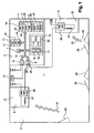
- the figure 1 represents a schematic view of a room comprising a heating device according to the invention.
- a heating device 1 is generally installed in a room 2. Such a heating device 1 has the function of maintaining a temperature 3 of the room 2, called ambient temperature 3, at a certain temperature 4, called the set temperature 4.
- the heating device comprises one or more heat emitters 5.
- the device 1 according to the invention comprises a thermostat 6.
- a thermostat 6 can set the set temperature 4 for one or more heat emitters 5.
- the thermostat 6 comprises a device for regulating the heating device.
- This control device comprises a microprocessor 7, an input interface 8, an output interface 9, a data memory 10, a program memory 11, a communication bus 12, a control box 13.
- input 8 serves to receive data and energy useful for the thermostat.
- the input interface receives the ambient temperature 3 read by a probe 14.
- the communication bus 12 connects all the elements present in the thermostat 6.
- the ambient temperature 3 can be stored in the data memory 10
- This ambient temperature 3 is used by the microprocessor 7, as well as other data contained in the data memory 10, to calculate a running rate 15 to be applied for the heat emitter (s) 5.
- the calculation of the rate of operation 15 is done by means of a control program 16.
- the control program 16 is stored in the program memory 11.
- the set temperature 4 is defined by a user of the thermostat 6 by means of the control box 13.
- the control box comprises an adjustment device 17.
- the adjustment device 17 comprises a "plus” button 18 and a "minus” button 19. These buttons 18 and 19 allow a user of the thermostat 6 to set the set temperature 4.
- the control box 13 may comprise a display device 20, for example a backlit LCD screen 20. It is conceivable to replace the adjustment buttons 18 and 19 as well as the LCD screen 20 by a graduated mechanical wheel.
- thermostat 6 simultaneously controlling a first heat emitter 21 and a second heat emitter 22
- a user of said thermostat 6 may be possible for a user of said thermostat 6 to define a first set temperature 23 for the first heat emitter 21 and a second setpoint temperature 24 for the second heat emitter 22.
- the two setpoint temperatures 23 and 24 defined can then be different. These two setpoint temperatures 23 and 24 can be displayed simultaneously on the LCD 20.
- the operating rates calculated by the microprocessor are incorporated in heating instructions.
- the heating instructions circulate via the bus from the microprocessor 7 to the output interface 9.
- the output interface 9 then sends said heating instructions to be applied to the heat emitters 21 and 22.
- Each heat emitter comprises a management box 26.
- a management box 26 receives on the one hand the energy necessary for the operation of the heat emitter and, on the other hand, the heating instructions to be applied. .
- the operating rate corresponding to these heating instructions is then applied, for example to a resistor 27. It is this resistor 27 that heats the room 2 as a function of the operating rate 15.
- the housing 26 sends back to the regulator the value of the current rate of operation of the heat emitter.
- a cold air inlet 30 can take place if the window 28 and / or the door 29 are to open.
- the arrival of cold air 30 abruptly drops the ambient temperature 3. This fall in ambient temperature 3 must be compensated by the heating device 1.
- the heating device 1 comprises two heat emitters 21 and 22, if one of the two heat emitters is badly
- the heat transmitter 21 or 22 remaining is the only heat transmitter 21 or 22 operational to try to maintain the ambient temperature 3 at the set temperature 4. This situation also happens when one of the emitters heat 21 or 22 breaks down.
- the operating rate of the operational apparatus may be such that the heat emitter must operate at or near its maximum capacity continuously. Prolonged use at or near a maximum run rate of 15 is detrimental to said heat emitter and may result in faster degradation or malfunction of said heat emitter. It is therefore important to avoid operation at a too long critical regime of the heat emitter.
- the method according to the invention comprises a cyclic step during which the set temperature 4 is raised.
- the method according to the invention comprises a cyclic step during which the ambient temperature 3 is measured.
- the operating rate to be applied to the transmitter 5 is then calculated by the microprocessor 7 as a function of these temperatures.
- the method according to the invention furthermore comprises a step of observation 31 of the gait rates 15, called the observation phase 31.
- the observation phase 31 can be decomposed into cycles 32.
- a cycle can for example have a duration of the order of half a minute or minute.
- An observation phase 31 can count up to a number n of cycles 32, n being an integer at least equal to 2.
- the maximum number n of cycles 32 of an observation phase 31 is stored in the memory of 10. This number n can be defined using the control unit 13 of the thermostat 6. For example, a number n between 8 and 10 can be used.
- the value of the current running rate of the heat emitter 5 is transmitted by the housing 26 to the interface 9, then said value is stored in the data memory 10.
- the observation phase 31 serves to verify that the rate of operation of a heat emitter is not critical.
- a critical rate of operation is a rate of operation greater than or equal to a critical value.
- critical value 33 represents a rate of operation above which continuous operation of the heat emitter may damage said emitter.
- the critical value can for example be defined at 85% of duty ratio, and thus stored in the data memory 10.
- n cycles 32 of the observation phase makes it possible to ensure that a critical operating rate observed during an isolated cycle 32 does not correspond to an observation error or to a definition of the operating rate. seeks to verify that this critical rate of operation is observed in several consecutive cycles, indicating that this rate is defined by the heating instructions.
- Each observation phase 31 is followed by a step during which the set temperature 4 can be modified. This change is made according to the operating rate observed during the n cycles 32 of the observation phase 31, and compared with the critical value 33. The modified setpoint temperature 4 obtained is then used to calculate the operating rate. until the next change of the set temperature 4.
- the number y is an integer greater than or equal to 1, and less than or equal to the number n of cycles 32. This number is stored in the data memory 10 and can optionally be defined using the control unit 13 of the thermostat 6.
- This decrease in the set temperature 4 generates the calculation of a new step rate 15, which is applied during the next observation phase 31. If during the next observation phase 31, critical operating rates are still observed and stored in the memory 10, the set temperature 4 is again decreased. These steps are repeated until the observed run rates are no longer critical run rates and the ambient temperature 3 is as close as possible to the user set point temperature 4.
- the method according to the invention thus avoids a degradation of the heat emitters 5 by modifying the set temperature 4 so that a set temperature 34 applied to define the step 15 is such that said step rate is not critical.
- the set temperature 34 applied may therefore be different from a user-defined set point temperature, called the initial setpoint temperature. It is preferable to return the set temperature 34 applied as close as possible to the initial set temperature 35, as soon as the event having caused the change of the ambient temperature 3 is completed. The end of such an event is for example the moment when the window 28 or the door 29 is closed.
- the initial set temperature 35 is stored in the data memory 10. It constitutes a maximum limit of the set temperature 4. Therefore, if the set temperature 34 applied is different from the initial set temperature 35, this set temperature 34 applied is necessarily lower than the initial set temperature 35.
- the thermostat 6 of the heating device 1 may have to set a rate of walk 15 of 100%.
- the observation phase 31 shows that the step rate is 100%.
- the method according to the invention then stores in the data memory 10 the initial setpoint temperature 35 and applies a modified setpoint temperature 34 to define the operating rate 15 for the next observation phase 31.
- the method according to the invention provides for decreasing the set temperature 34 applied as long as the observed operating rate remains critical, that is to say greater than or equal to the critical value 33.
- the window 28 is closed, there is no more cold air supply.
- the balance between the incoming cold air and the heat emission of the heat emitter is disturbed, that is, the heat emission no longer compensates for a cold air supply.
- the emission of heat from the transmitter 5 then raises the ambient temperature 3 in the room 2.
- One embodiment of the invention provides that if the set temperature 34 applied to define the operating rate 15 is lower than the initial set temperature 35 and that the observed operating rate is not critical, the modification of the set temperature 34 applied consists of an increase of said temperature. Such increases in the applied set temperature 34 may occur until the initial set temperature is reached, or a critical run rate is observed again in an observation phase.
- a preferred mode of embodiment of the invention provides that if during an observation phase 31, the ambient temperature 3 increases during z 32 consecutive cycles, the current observation phase 31 is stopped.
- the number z is an integer greater than or equal to 1, and less than or equal to the number n of cycles 32.
- a number z is equal to 5.
- a modification of the set temperature 34 applied is performed. More precisely, this modification is an increase in the set temperature 34 applied.
- a new observation phase 31 then starts with a running rate 15 calculated with respect to this new set temperature 34 applied.
- a preferred embodiment of the invention provides a standard deviation 36 of temperature comparison, called step 36.
- the value of such a step is defined in the memory 10. This value can be set in FIG. order of degree Celsius.
- the ambient temperature 3 is at least two steps 36 lower than the set temperature 34 applied, said set temperature 34 is reduced by a step 36.
- said set temperature 34 is made equal to the ambient temperature 3 increased by a step 36.
- an embodiment of the invention provides for the heating device 1 to be moved to an anti-freeze mode of operation in a certain situation.
- An anti-freeze operating mode corresponds to the maintenance of a minimum setpoint temperature 4, for example 5 ° C. which prevents the formation of gel in the room. The value of this minimum temperature is stored in the memory 10.
- the transition to the frost-free mode takes place if the observed operating rate is greater than or equal to the critical value 33 during a number m of the observation phase 31 consecutive, and if the rate the current observation phase is equal to 100%.
- the number m is an integer greater than or equal to 2, stored in the data memory 10.
- a number m is used equal to 3.
- Such a situation corresponds to a large difference between the set temperature 34 applied and the ambient temperature 3. In such a situation, it is considered that the heating device is not capable of supplying enough heat to reach the set temperature.
- the frost protection mode is a backup measure of room 2.
- the device switches to frost-free mode if the observed operating rate is greater than or equal to the critical value 33 during a consecutive number m of observation phase 31, and if the operating rate on the current observation phase is equal to 100%, and if the ambient temperature 3 is lower than the minimum set temperature 4 corresponding to the frost-free operating mode, the device switches to frost-free mode.
- the operating rate is simply limited to the critical value 33.
- the end of this limitation of the rate of operation 15 takes effect following an increase of the ambient temperature 3 during the number of cycles 32 necessary to restart an observation phase 31 as in the embodiment described above. .
- the ambient temperature 3 going up, a new observation phase 31 begins, with the definition of a new rate of operation 15 and possibly an increase in the set temperature 34 applied.
- Another preferred embodiment of the process according to the invention makes it possible to reach more quickly a non-critical operating rate in the presence of a large difference in temperature between the set temperature 34 applied and the ambient temperature 3.
- This mode provides that, if the running rate 15 is 100% during all the cycles of the observation phase 31, the decrease in the set temperature 34 is two steps 36 instead of one.
- the figure 2 is a graphical representation of the ambient temperature and the set temperature as a function of time, during a use of the method according to an exemplary embodiment of the invention in a heating device.
- a room 2 having a window 28 is heated by a heating device 1.
- the window 28 is wide open.
- the ambient temperature 3 decreases during n cycles 32, while the operating rate is 100%, which is greater than a critical value 33 defined as equal to 85%.
- a modification step 38 decreases the set temperature 34 applied.
- the set temperature 34 applied is greater by more than two steps 36 at room temperature.
- the set temperature 34 applied during an observation phase 39 is therefore the set temperature of the observation phase 37 decreased by a step 36.
- the ambient temperature continues to fall and the rate of walking is always 100%.
- the set temperature used 34 is greater than the ambient temperature 3 of less than two steps 36.
- the set temperature 34 applied for a third observation phase 40 is therefore equal to the ambient temperature 3 plus a step.
- the step rate remains at 100% but the ambient temperature 3 still does not increase during the n cycles 32.
- the step rate 15 is greater than the critical value of 85%.
- the step rate is equal to 100% during the observation phase 40.
- the number m of consecutive observation phases 31 to limit the step rate is equal to 3.
- an observation phase 41 the rate of operation is thus limited to 85%, since the ambient temperature 3 is greater than a temperature defined by the frost-free mode of the heating device 1.
- window 28 is now in the open position, the arrival of cold air is then limited.
- the ambient temperature 3 then rises during z consecutive cycles 32, the number z being here equal to 5.
- the observation phase 41 is thus stopped and an observation phase 42 begins.
- the set temperature 34 applied during the observation phase 42 is defined as being equal to the ambient temperature 3 increased by a step 36.
- the ambient temperature 3 increases during 5 consecutive cycles during the observation phase 42.
- observation 42 is then interrupted.
- the set temperature 34 applied during an observation phase 43 is defined as equal to the ambient temperature 3 increased by a step 36.
- the window 28 is completely opened again.
- the ambient temperature 3 therefore does not increase during the n cycles 32 of the observation phase 43.
- the operating rate during the observation phase 43 is 100%.
- the observation phases 41, 42 and 43 having a running rate greater than or equal to the critical value 33 of 85%, and the operating rate 15 of the observation phase 43 being 100%, the operating ratio 15 during an observation phase 44 is limited to 85%.
- observation phase 44 the window is closed again.
- the arrival of cold air is then interrupted.
- the ambient temperature then rises for five consecutive cycles and a new observation phase 45 is initialized.
- the set temperature 34 defined for this observation phase 45 is equal to the ambient temperature 3 increased by a step 36 and the operating ratio 15 is between 85% and 100%.
- the ambient temperature 3 increases, the observation phase 45 only lasts five cycles 32 before being stopped, as well as an observation phase 46 and an observation phase 47 for which the set temperature used is equal to the room temperature increased by one step.
- the ambient temperature 3 is less than one step 36 less than the set temperature defined by the user at the end of the observation phase 47.
- An observation phase 48 therefore takes place with a set temperature 34 equal to the set temperature 35 defined by the user.
Claims (10)
- Heizverfahren mithilfe eines Heizgerätes umfassend zumindest einen Wärmestrahler (5), einen Thermostaten (6) und eine Sonde (14), wobei das Verfahren folgendes umfasst:- einen Schritt, im Laufe dessen man das Heizgerät mit Energie versorgt,- einen Schritt, im Laufe dessen von der Sonde eine Umgebungstemperatur (3) gemessen wird,- einen Schritt, im Laufe dessen eine Solltemperatur (4) definiert wird,- einen Schritt zum Übertragen von Heizinstruktionen (25) an den Wärmestrahler unter Berücksichtigung dieser Temperaturen,- eine Phase (31) der Beobachtung, umfassend n Zyklen (32), wobei in jedem der Zyklen in einem Datenspeicher (10) eine Betriebsquote (15) des Wärmestrahlers abgespeichert wird, und n eine Ganzzahl zumindest gleich 2 ist,- einen Schritt, im Laufe dessen die Solltemperatur in Abhängigkeit von den in der Beobachtungsphase gespeicherten Betriebsquoten verändert werden kann,
wobei das besagte Verfahren dadurch gekennzeichnet ist, dass:- die Solltemperatur (34) infolge einer Beobachtungsphase (31) verringert wird, wenn die beobachtete Betriebsquote während einer Mindestanzahl y an Zyklen der besagten Beobachtungsphase größer oder gleich einem kritischen Wert (33) ist, wobei y eine Ganzzahl zwischen 1 und n ist,- die Solltemperatur (34) infolge einer Beobachtungsphase (31) erhöht wird, wenn die folgenden Bedingungen erfüllt werden:- die beobachtete Betriebsquote in allen Zyklen der besagten Beobachtungsphase kleiner ist, als ein kritischer Wert (33), und- die Solltemperatur (34) geringer ist, als die ursprüngliche Solltemperatur (35), und- die Umgebungstemperatur während der besagten Beobachtungsphase angestiegen ist. - Verfahren nach Anspruch 1, dadurch gekennzeichnet, dass die geänderte Solltemperatur (34) die ursprüngliche Solltemperatur (35), die durch einen Benutzer des Heizgerätes definiert worden ist, nicht übersteigen kann.
- Verfahren nach einem der Ansprüche 1 bis 2, dadurch gekennzeichnet, dass, wenn die Umgebungstemperatur um zumindest zwei Standardabweichungen oder Stufen (36) geringer ist, als die Solltemperatur (34), die während der Beobachtungsphase angewandt wurde, die Solltemperatur nach der besagten Beobachtungsphase um eine Stufe gesenkt wird.
- Verfahren nach einem der Ansprüche 1 bis 3, dadurch gekennzeichnet, dass, wenn die Umgebungstemperatur um weniger als zwei Standardabweichungen oder Stufen (36) geringer ist, als die Solltemperatur (34), die während der Beobachtungsphase angewandt wurde, die Solltemperatur an die nach der besagten Beobachtungsphase um eine Stufe angehobene Umgebungstemperatur angeglichen wird.
- Verfahren nach einem der Ansprüche 1 bis 4, dadurch gekennzeichnet, dass, wenn die Umgebungstemperatur während einer Beobachtungsphase nach einem Änderungsschritt der Solltemperatur nicht erhöht worden ist, und wenn die Betriebsquote (15) während der Beobachtungsphase über dem kritischen Wert (33) liegt, die Betriebsquote nach der besagten Beobachtungsphase auf den besagten kritischen Wert begrenzt wird.
- Verfahren nach einem der Ansprüche 1 bis 5, dadurch gekennzeichnet, dass, wenn die Umgebungstemperatur innerhalb von 5 aufeinander folgenden Zyklen (32) ansteigt, die laufende Beobachtungsphase (31) unterbrochen, und die Solltemperatur erhöht wird.
- Verfahren nach einem der Ansprüche 1 bis 6, dadurch gekennzeichnet, dass, wenn die beobachtete Betriebsquote innerhalb von m aufeinander folgenden Beobachtungsphasen, mit m als Ganzzahl größer oder gleich 2, größer oder gleich dem kritischen Wert ist, und wenn die beobachtete Betriebsquote während der laufenden Beobachtungsphase gleich 100% ist, und wenn die Umgebungstemperatur geringer ist, als die Solltemperatur, die für einen Frostschutzmodus definiert wurde, das Gerät in den Frostschutzmodus übergeht.
- Verfahren nach einem der Ansprüche 1 bis 7, dadurch gekennzeichnet, dass, wenn die beobachtete Betriebsquote innerhalb von m aufeinander folgenden Beobachtungsphasen, mit m als Ganzzahl größer oder gleich 2, größer oder gleich dem kritischen Wert ist, und wenn die beobachtete Betriebsquote während der laufenden Beobachtungsphase gleich 100% ist, und wenn die Umgebungstemperatur höher ist, als die Solltemperatur, die für einen Frostschutzmodus definiert wurde, die Betriebsquote auf den kritischen Wert beschränkt wird.
- Verfahren nach einem der Ansprüche 1 bis 8, dadurch gekennzeichnet, dass wenn die Betriebsquote während aller Zyklen der Beobachtungsphase gleich 100% ist, die Solltemperatur nach dieser Beobachtungsphase um zwei Standardabweichungen oder Stufen (36) abgesenkt wird.
- Heizgerät, das mit Geräten zur Umsetzung eines Verfahrens nach einem der Ansprüche 1 bis 9 ausgestattet ist.
Applications Claiming Priority (2)
| Application Number | Priority Date | Filing Date | Title |
|---|---|---|---|
| FR0852449A FR2930055B1 (fr) | 2008-04-11 | 2008-04-11 | Procede d'equilibrage de puissance d'un dispositif de chauffage. |
| PCT/FR2009/000399 WO2009133288A1 (fr) | 2008-04-11 | 2009-04-03 | Procede d'equilibrage de puissance d'un dispositif de chauffage |
Publications (2)
| Publication Number | Publication Date |
|---|---|
| EP2277090A1 EP2277090A1 (de) | 2011-01-26 |
| EP2277090B1 true EP2277090B1 (de) | 2012-11-07 |
Family
ID=40220138
Family Applications (1)
| Application Number | Title | Priority Date | Filing Date |
|---|---|---|---|
| EP09738322A Active EP2277090B1 (de) | 2008-04-11 | 2009-04-03 | Verfahren zur symmetrierung der leistung eines heizgerätes |
Country Status (3)
| Country | Link |
|---|---|
| EP (1) | EP2277090B1 (de) |
| FR (1) | FR2930055B1 (de) |
| WO (1) | WO2009133288A1 (de) |
Families Citing this family (1)
| Publication number | Priority date | Publication date | Assignee | Title |
|---|---|---|---|---|
| FR2962234B1 (fr) * | 2010-07-01 | 2012-07-27 | Atlantic Industrie Sas | Procede de detection de l'ouverture et de la fermeture d'un ouvrant dans une piece et dispositif de regulation thermique mettant en ?uvre ce procede |
Family Cites Families (3)
| Publication number | Priority date | Publication date | Assignee | Title |
|---|---|---|---|---|
| FR2465388A1 (fr) * | 1979-09-07 | 1981-03-20 | Messier Sa | Procede et dispositif de regulation du fonctionnement d'une installation de chauffage electrique de locaux |
| FR2466717A1 (fr) * | 1979-10-03 | 1981-04-10 | Radiotechnique Compelec | Dispositif combine de delestage et de programmation d'une installation de chauffage electrique |
| DE3525315A1 (de) * | 1985-03-25 | 1986-09-25 | Accum AG, Gossau | Verfahren zum steuern von einzelspeichern |
-
2008
- 2008-04-11 FR FR0852449A patent/FR2930055B1/fr active Active
-
2009
- 2009-04-03 EP EP09738322A patent/EP2277090B1/de active Active
- 2009-04-03 WO PCT/FR2009/000399 patent/WO2009133288A1/fr active Application Filing
Also Published As
| Publication number | Publication date |
|---|---|
| FR2930055A1 (fr) | 2009-10-16 |
| EP2277090A1 (de) | 2011-01-26 |
| WO2009133288A1 (fr) | 2009-11-05 |
| FR2930055B1 (fr) | 2023-04-28 |
Similar Documents
| Publication | Publication Date | Title |
|---|---|---|
| FR2929691A1 (fr) | Procede d'auto-equilibrage d'un dispositif de chauffage | |
| EP2956984B1 (de) | Verfahren zur regelung der temperatur eines akkus | |
| EP0742917B1 (de) | Verfahren und vorrichtung zur verminderung des rauschpegels eines mikrorechners | |
| FR3025871B1 (fr) | Equipement de controle d'au moins un appareil de regulation thermique, et ensemble de regulation et systeme de pilotage associes | |
| EP2277090B1 (de) | Verfahren zur symmetrierung der leistung eines heizgerätes | |
| FR3027061A1 (fr) | Procede et dispositif de notification d'une autorisation d'arret complet d'un moteur a turbine a gaz d'aeronef | |
| EP2850709B1 (de) | Elektronische vorrichtung zum schutz eines elektrischen leiters und verfahren zur steuerung solch einer vorrichtung | |
| FR3039462B1 (fr) | Dispositif de chauffage et procede de gestion associe | |
| EP2339255A1 (de) | Verfahren zur optimierten Steuerung eines Temperaturreglers | |
| EP3867093B1 (de) | System zur vor-ort-diagnose der batterie eines elektrischen fahrrades | |
| FR3008501A1 (fr) | Procede de regulation de chauffage electrique en cas d’ouverture de fenetre | |
| WO2021140251A1 (fr) | Système et procédé de chauffage | |
| FR2997233A1 (fr) | Gestion de batterie d'un vehicule non branche a une source d'energie externe | |
| EP3650762A1 (de) | Kontrollverfahren einer thermischen leistung zum einspritzen in ein heizsystem, und dieses verfahren nutzendes heizsystem | |
| EP2834490B1 (de) | Schätzung des wärmezustandes eines motors | |
| EP0826934B1 (de) | Verfahren zur Steuerung des Ladens und Entladens von elektrischen Speicherheizgeräten | |
| FR3067068B1 (fr) | Eolienne ayant une unite de commande assurant une regulation de la vitesse de rotation du rotor | |
| FR2978702A1 (fr) | Procede de refroidissement d'une batterie electrique d'un vehicule automobile et dispositif de refroidissement | |
| FR3018150A1 (fr) | Appareil et procede de chauffage electrique presentant une fonction d'effacement | |
| EP1199621B1 (de) | Temperaturregelverfahren in einem Elektrobackofen | |
| FR3046873B1 (fr) | Procede et dispositif de protection d'une architecture electrique | |
| EP2515405B1 (de) | Wärmeschutzeinheit und Verfahren, bei dem eine solche Einheit verwendendet wird | |
| EP2783185A1 (de) | Verfahren zur steuerung des energieverbrauchs einer industriellen infrastruktur in echtzeit | |
| FR3101446A1 (fr) | Procédé de gestion thermique, notamment pour véhicule automobile, et unité de commande associée | |
| FR3101508A1 (fr) | Procédé de gestion thermique, notamment pour véhicule automobile, et unité de commande associée |
Legal Events
| Date | Code | Title | Description |
|---|---|---|---|
| PUAI | Public reference made under article 153(3) epc to a published international application that has entered the european phase |
Free format text: ORIGINAL CODE: 0009012 |
|
| 17P | Request for examination filed |
Effective date: 20101022 |
|
| AK | Designated contracting states |
Kind code of ref document: A1 Designated state(s): AT BE BG CH CY CZ DE DK EE ES FI FR GB GR HR HU IE IS IT LI LT LU LV MC MK MT NL NO PL PT RO SE SI SK TR |
|
| AX | Request for extension of the european patent |
Extension state: AL BA RS |
|
| 17Q | First examination report despatched |
Effective date: 20110316 |
|
| DAX | Request for extension of the european patent (deleted) | ||
| GRAP | Despatch of communication of intention to grant a patent |
Free format text: ORIGINAL CODE: EPIDOSNIGR1 |
|
| GRAS | Grant fee paid |
Free format text: ORIGINAL CODE: EPIDOSNIGR3 |
|
| GRAA | (expected) grant |
Free format text: ORIGINAL CODE: 0009210 |
|
| AK | Designated contracting states |
Kind code of ref document: B1 Designated state(s): AT BE BG CH CY CZ DE DK EE ES FI FR GB GR HR HU IE IS IT LI LT LU LV MC MK MT NL NO PL PT RO SE SI SK TR |
|
| REG | Reference to a national code |
Ref country code: GB Ref legal event code: FG4D Free format text: NOT ENGLISH |
|
| REG | Reference to a national code |
Ref country code: CH Ref legal event code: EP Ref country code: AT Ref legal event code: REF Ref document number: 583242 Country of ref document: AT Kind code of ref document: T Effective date: 20121115 |
|
| REG | Reference to a national code |
Ref country code: IE Ref legal event code: FG4D Free format text: LANGUAGE OF EP DOCUMENT: FRENCH |
|
| REG | Reference to a national code |
Ref country code: DE Ref legal event code: R096 Ref document number: 602009011022 Country of ref document: DE Effective date: 20130103 |
|
| REG | Reference to a national code |
Ref country code: AT Ref legal event code: MK05 Ref document number: 583242 Country of ref document: AT Kind code of ref document: T Effective date: 20121107 |
|
| REG | Reference to a national code |
Ref country code: NL Ref legal event code: VDEP Effective date: 20121107 |
|
| REG | Reference to a national code |
Ref country code: LT Ref legal event code: MG4D |
|
| PG25 | Lapsed in a contracting state [announced via postgrant information from national office to epo] |
Ref country code: FI Free format text: LAPSE BECAUSE OF FAILURE TO SUBMIT A TRANSLATION OF THE DESCRIPTION OR TO PAY THE FEE WITHIN THE PRESCRIBED TIME-LIMIT Effective date: 20121107 Ref country code: NL Free format text: LAPSE BECAUSE OF FAILURE TO SUBMIT A TRANSLATION OF THE DESCRIPTION OR TO PAY THE FEE WITHIN THE PRESCRIBED TIME-LIMIT Effective date: 20121107 Ref country code: SE Free format text: LAPSE BECAUSE OF FAILURE TO SUBMIT A TRANSLATION OF THE DESCRIPTION OR TO PAY THE FEE WITHIN THE PRESCRIBED TIME-LIMIT Effective date: 20121107 Ref country code: HR Free format text: LAPSE BECAUSE OF FAILURE TO SUBMIT A TRANSLATION OF THE DESCRIPTION OR TO PAY THE FEE WITHIN THE PRESCRIBED TIME-LIMIT Effective date: 20121107 Ref country code: LT Free format text: LAPSE BECAUSE OF FAILURE TO SUBMIT A TRANSLATION OF THE DESCRIPTION OR TO PAY THE FEE WITHIN THE PRESCRIBED TIME-LIMIT Effective date: 20121107 Ref country code: NO Free format text: LAPSE BECAUSE OF FAILURE TO SUBMIT A TRANSLATION OF THE DESCRIPTION OR TO PAY THE FEE WITHIN THE PRESCRIBED TIME-LIMIT Effective date: 20130207 Ref country code: IS Free format text: LAPSE BECAUSE OF FAILURE TO SUBMIT A TRANSLATION OF THE DESCRIPTION OR TO PAY THE FEE WITHIN THE PRESCRIBED TIME-LIMIT Effective date: 20130307 |
|
| PG25 | Lapsed in a contracting state [announced via postgrant information from national office to epo] |
Ref country code: GR Free format text: LAPSE BECAUSE OF FAILURE TO SUBMIT A TRANSLATION OF THE DESCRIPTION OR TO PAY THE FEE WITHIN THE PRESCRIBED TIME-LIMIT Effective date: 20130208 Ref country code: LV Free format text: LAPSE BECAUSE OF FAILURE TO SUBMIT A TRANSLATION OF THE DESCRIPTION OR TO PAY THE FEE WITHIN THE PRESCRIBED TIME-LIMIT Effective date: 20121107 Ref country code: PL Free format text: LAPSE BECAUSE OF FAILURE TO SUBMIT A TRANSLATION OF THE DESCRIPTION OR TO PAY THE FEE WITHIN THE PRESCRIBED TIME-LIMIT Effective date: 20121107 Ref country code: PT Free format text: LAPSE BECAUSE OF FAILURE TO SUBMIT A TRANSLATION OF THE DESCRIPTION OR TO PAY THE FEE WITHIN THE PRESCRIBED TIME-LIMIT Effective date: 20130307 Ref country code: SI Free format text: LAPSE BECAUSE OF FAILURE TO SUBMIT A TRANSLATION OF THE DESCRIPTION OR TO PAY THE FEE WITHIN THE PRESCRIBED TIME-LIMIT Effective date: 20121107 |
|
| PG25 | Lapsed in a contracting state [announced via postgrant information from national office to epo] |
Ref country code: AT Free format text: LAPSE BECAUSE OF FAILURE TO SUBMIT A TRANSLATION OF THE DESCRIPTION OR TO PAY THE FEE WITHIN THE PRESCRIBED TIME-LIMIT Effective date: 20121107 |
|
| PG25 | Lapsed in a contracting state [announced via postgrant information from national office to epo] |
Ref country code: EE Free format text: LAPSE BECAUSE OF FAILURE TO SUBMIT A TRANSLATION OF THE DESCRIPTION OR TO PAY THE FEE WITHIN THE PRESCRIBED TIME-LIMIT Effective date: 20121107 Ref country code: SK Free format text: LAPSE BECAUSE OF FAILURE TO SUBMIT A TRANSLATION OF THE DESCRIPTION OR TO PAY THE FEE WITHIN THE PRESCRIBED TIME-LIMIT Effective date: 20121107 Ref country code: CZ Free format text: LAPSE BECAUSE OF FAILURE TO SUBMIT A TRANSLATION OF THE DESCRIPTION OR TO PAY THE FEE WITHIN THE PRESCRIBED TIME-LIMIT Effective date: 20121107 Ref country code: BG Free format text: LAPSE BECAUSE OF FAILURE TO SUBMIT A TRANSLATION OF THE DESCRIPTION OR TO PAY THE FEE WITHIN THE PRESCRIBED TIME-LIMIT Effective date: 20130207 Ref country code: DK Free format text: LAPSE BECAUSE OF FAILURE TO SUBMIT A TRANSLATION OF THE DESCRIPTION OR TO PAY THE FEE WITHIN THE PRESCRIBED TIME-LIMIT Effective date: 20121107 |
|
| PG25 | Lapsed in a contracting state [announced via postgrant information from national office to epo] |
Ref country code: IT Free format text: LAPSE BECAUSE OF FAILURE TO SUBMIT A TRANSLATION OF THE DESCRIPTION OR TO PAY THE FEE WITHIN THE PRESCRIBED TIME-LIMIT Effective date: 20121107 Ref country code: RO Free format text: LAPSE BECAUSE OF FAILURE TO SUBMIT A TRANSLATION OF THE DESCRIPTION OR TO PAY THE FEE WITHIN THE PRESCRIBED TIME-LIMIT Effective date: 20121107 |
|
| PLBE | No opposition filed within time limit |
Free format text: ORIGINAL CODE: 0009261 |
|
| STAA | Information on the status of an ep patent application or granted ep patent |
Free format text: STATUS: NO OPPOSITION FILED WITHIN TIME LIMIT |
|
| 26N | No opposition filed |
Effective date: 20130808 |
|
| BERE | Be: lapsed |
Owner name: SOC. MULLER & CIE Effective date: 20130430 |
|
| PG25 | Lapsed in a contracting state [announced via postgrant information from national office to epo] |
Ref country code: ES Free format text: LAPSE BECAUSE OF FAILURE TO SUBMIT A TRANSLATION OF THE DESCRIPTION OR TO PAY THE FEE WITHIN THE PRESCRIBED TIME-LIMIT Effective date: 20130218 |
|
| PG25 | Lapsed in a contracting state [announced via postgrant information from national office to epo] |
Ref country code: CY Free format text: LAPSE BECAUSE OF FAILURE TO SUBMIT A TRANSLATION OF THE DESCRIPTION OR TO PAY THE FEE WITHIN THE PRESCRIBED TIME-LIMIT Effective date: 20121107 Ref country code: MC Free format text: LAPSE BECAUSE OF FAILURE TO SUBMIT A TRANSLATION OF THE DESCRIPTION OR TO PAY THE FEE WITHIN THE PRESCRIBED TIME-LIMIT Effective date: 20121107 |
|
| REG | Reference to a national code |
Ref country code: CH Ref legal event code: PL |
|
| REG | Reference to a national code |
Ref country code: DE Ref legal event code: R097 Ref document number: 602009011022 Country of ref document: DE Effective date: 20130808 |
|
| GBPC | Gb: european patent ceased through non-payment of renewal fee |
Effective date: 20130403 |
|
| REG | Reference to a national code |
Ref country code: IE Ref legal event code: MM4A |
|
| PG25 | Lapsed in a contracting state [announced via postgrant information from national office to epo] |
Ref country code: BE Free format text: LAPSE BECAUSE OF NON-PAYMENT OF DUE FEES Effective date: 20130430 Ref country code: GB Free format text: LAPSE BECAUSE OF NON-PAYMENT OF DUE FEES Effective date: 20130403 Ref country code: CH Free format text: LAPSE BECAUSE OF NON-PAYMENT OF DUE FEES Effective date: 20130430 Ref country code: LI Free format text: LAPSE BECAUSE OF NON-PAYMENT OF DUE FEES Effective date: 20130430 |
|
| PG25 | Lapsed in a contracting state [announced via postgrant information from national office to epo] |
Ref country code: IE Free format text: LAPSE BECAUSE OF NON-PAYMENT OF DUE FEES Effective date: 20130403 |
|
| PG25 | Lapsed in a contracting state [announced via postgrant information from national office to epo] |
Ref country code: MT Free format text: LAPSE BECAUSE OF FAILURE TO SUBMIT A TRANSLATION OF THE DESCRIPTION OR TO PAY THE FEE WITHIN THE PRESCRIBED TIME-LIMIT Effective date: 20121107 |
|
| PG25 | Lapsed in a contracting state [announced via postgrant information from national office to epo] |
Ref country code: TR Free format text: LAPSE BECAUSE OF FAILURE TO SUBMIT A TRANSLATION OF THE DESCRIPTION OR TO PAY THE FEE WITHIN THE PRESCRIBED TIME-LIMIT Effective date: 20121107 |
|
| PG25 | Lapsed in a contracting state [announced via postgrant information from national office to epo] |
Ref country code: MK Free format text: LAPSE BECAUSE OF FAILURE TO SUBMIT A TRANSLATION OF THE DESCRIPTION OR TO PAY THE FEE WITHIN THE PRESCRIBED TIME-LIMIT Effective date: 20121107 Ref country code: HU Free format text: LAPSE BECAUSE OF FAILURE TO SUBMIT A TRANSLATION OF THE DESCRIPTION OR TO PAY THE FEE WITHIN THE PRESCRIBED TIME-LIMIT; INVALID AB INITIO Effective date: 20090403 Ref country code: LU Free format text: LAPSE BECAUSE OF NON-PAYMENT OF DUE FEES Effective date: 20130403 |
|
| REG | Reference to a national code |
Ref country code: FR Ref legal event code: PLFP Year of fee payment: 8 |
|
| REG | Reference to a national code |
Ref country code: FR Ref legal event code: PLFP Year of fee payment: 9 |
|
| REG | Reference to a national code |
Ref country code: FR Ref legal event code: PLFP Year of fee payment: 10 |
|
| PGFP | Annual fee paid to national office [announced via postgrant information from national office to epo] |
Ref country code: FR Payment date: 20230309 Year of fee payment: 15 |
|
| PGFP | Annual fee paid to national office [announced via postgrant information from national office to epo] |
Ref country code: DE Payment date: 20230412 Year of fee payment: 15 |