EP2277090B1 - Method for balancing the power of a heating device - Google Patents
Method for balancing the power of a heating device Download PDFInfo
- Publication number
- EP2277090B1 EP2277090B1 EP09738322A EP09738322A EP2277090B1 EP 2277090 B1 EP2277090 B1 EP 2277090B1 EP 09738322 A EP09738322 A EP 09738322A EP 09738322 A EP09738322 A EP 09738322A EP 2277090 B1 EP2277090 B1 EP 2277090B1
- Authority
- EP
- European Patent Office
- Prior art keywords
- set temperature
- during
- observation phase
- temperature
- equal
- Prior art date
- Legal status (The legal status is an assumption and is not a legal conclusion. Google has not performed a legal analysis and makes no representation as to the accuracy of the status listed.)
- Active
Links
Images

Classifications
-
- G—PHYSICS
- G05—CONTROLLING; REGULATING
- G05D—SYSTEMS FOR CONTROLLING OR REGULATING NON-ELECTRIC VARIABLES
- G05D23/00—Control of temperature
- G05D23/19—Control of temperature characterised by the use of electric means
- G05D23/1902—Control of temperature characterised by the use of electric means characterised by the use of a variable reference value
- G05D23/1904—Control of temperature characterised by the use of electric means characterised by the use of a variable reference value variable in time
Definitions
- the present invention relates to a method of balancing the power of a heater.
- a heater is generally used to heat a room, for example a room in a house. More particularly, a heater is provided to maintain a substantially constant temperature in the room.
- the heating device generally comprises a heat emitter, a thermostat and a probe.
- the heat emitter is a heater that can be of any type known to those skilled in the art, for example an electric heater or a convector.
- the heat emitter operates according to a certain diet called the rate of operation.
- the rate of operation is defined as a percentage of a maximum power of the heat emitter. This rate of operation can not be greater than 100%.
- the duty rate used by a heater to maintain a substantially stable ambient temperature is calculated by the thermostat.
- the thermostat uses a reference temperature, typically the ambient temperature of the room. This reference temperature is read by the probe.
- the probe may be a room sensor, an outdoor sensor or any other type of probe for providing a reference temperature to the thermostat.
- the rate of operation is defined according to a set temperature.
- the set temperature represents the desired room temperature by the user. Thus, if the ambient temperature is 18 ° C and the set temperature is set to 20 ° C, the thermostat defines a rate of operation capable of raising the ambient temperature to 20 ° C.
- the characteristics of the heating devices are generally chosen according to the room to be equipped. If a device with a high heating capacity is installed in a room for which a device with a low heating capacity is sufficient, the heating device heats the room properly with a relatively low rate of operation. However, if a device having a low heating capacity is installed in a room requiring a device with a high heating capacity, the installed heater operates continuously at full speed, without even sometimes succeeding in heating the room properly.
- External elements may also require full operation of the heating device, for example a cold air inlet connected to a window or an open door. In such a situation, the heater may not be sufficient to maintain the room temperature at the set temperature. The heating device then operates at a maximum operating rate continuously, without managing to maintain the ambient temperature around the set temperature.
- Another solution may be to limit the maximum operating rate of a heating device. For example, it is possible to limit the operating rate when using a heating device to 80%. However such arbitrary limitation, if it avoids an intensive and harmful use of the heating device, does not allow an optimal use of said device. Such a solution is in fact to produce less powerful heating devices, but having a margin of safety of use.
- the heating method according to the invention comprises a step of supplying energy, a step of measuring the ambient temperature with the aid of a probe, a step of defining the set temperature with the help of a thermostat and a heating step taking into account the previous steps.
- the method according to the invention further provides an observation step, also called observation phase.
- This observation phase is intended to evaluate the operating rate of the heater to verify that the heater does not run over-speed.
- the document FR2466717 known from the state of the art, discloses a heating method comprising an observation phase, during which a rate of operation of the heat emitter is observed, as well as a step during which the temperature of the setpoint is modified according to the observed market rate.
- a single rate of operation is observed during each observation phase.
- the observation step is divided into n cycles, n being an integer at least equal to 2.
- n being an integer at least equal to 2.
- the method according to the invention provides a step during which the set temperature is changed according to the operating rate of the heating device. Typically, if the observation during several consecutive cycles shows that the rate of operation is too high continuously, the set temperature is reduced so as to avoid intensive use of the heating device.
- the current setpoint temperature is a setpoint temperature different from the setpoint temperature initially defined by a user, called the initial setpoint temperature.
- the current setpoint temperature is lower than the initial setpoint temperature, if it has been decreased to prevent overheating of the heater.
- the method according to the invention then increases the current setpoint temperature in order to approach the initial target temperature.
- the current setpoint temperature must not exceed the initial setpoint temperature.
- the set temperature is decreased if the duty ratio observed is greater than or equal to a critical value for a minimum number of said observation stage cycles.
- the set temperature is increased if the operating rate observed during all the cycles of said observation phase is lower than a critical value, if the set temperature is lower at the initial setpoint temperature and if the ambient temperature has increased during said observation phase.
- the modified set temperature can not exceed an initial target temperature defined by a user of the heating device.
- the invention also relates to a device provided with means for implementing such a method.
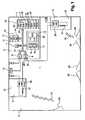
- the figure 1 represents a schematic view of a room comprising a heating device according to the invention.
- a heating device 1 is generally installed in a room 2. Such a heating device 1 has the function of maintaining a temperature 3 of the room 2, called ambient temperature 3, at a certain temperature 4, called the set temperature 4.
- the heating device comprises one or more heat emitters 5.
- the device 1 according to the invention comprises a thermostat 6.
- a thermostat 6 can set the set temperature 4 for one or more heat emitters 5.
- the thermostat 6 comprises a device for regulating the heating device.
- This control device comprises a microprocessor 7, an input interface 8, an output interface 9, a data memory 10, a program memory 11, a communication bus 12, a control box 13.
- input 8 serves to receive data and energy useful for the thermostat.
- the input interface receives the ambient temperature 3 read by a probe 14.
- the communication bus 12 connects all the elements present in the thermostat 6.
- the ambient temperature 3 can be stored in the data memory 10
- This ambient temperature 3 is used by the microprocessor 7, as well as other data contained in the data memory 10, to calculate a running rate 15 to be applied for the heat emitter (s) 5.
- the calculation of the rate of operation 15 is done by means of a control program 16.
- the control program 16 is stored in the program memory 11.
- the set temperature 4 is defined by a user of the thermostat 6 by means of the control box 13.
- the control box comprises an adjustment device 17.
- the adjustment device 17 comprises a "plus” button 18 and a "minus” button 19. These buttons 18 and 19 allow a user of the thermostat 6 to set the set temperature 4.
- the control box 13 may comprise a display device 20, for example a backlit LCD screen 20. It is conceivable to replace the adjustment buttons 18 and 19 as well as the LCD screen 20 by a graduated mechanical wheel.
- thermostat 6 simultaneously controlling a first heat emitter 21 and a second heat emitter 22
- a user of said thermostat 6 may be possible for a user of said thermostat 6 to define a first set temperature 23 for the first heat emitter 21 and a second setpoint temperature 24 for the second heat emitter 22.
- the two setpoint temperatures 23 and 24 defined can then be different. These two setpoint temperatures 23 and 24 can be displayed simultaneously on the LCD 20.
- the operating rates calculated by the microprocessor are incorporated in heating instructions.
- the heating instructions circulate via the bus from the microprocessor 7 to the output interface 9.
- the output interface 9 then sends said heating instructions to be applied to the heat emitters 21 and 22.
- Each heat emitter comprises a management box 26.
- a management box 26 receives on the one hand the energy necessary for the operation of the heat emitter and, on the other hand, the heating instructions to be applied. .
- the operating rate corresponding to these heating instructions is then applied, for example to a resistor 27. It is this resistor 27 that heats the room 2 as a function of the operating rate 15.
- the housing 26 sends back to the regulator the value of the current rate of operation of the heat emitter.
- a cold air inlet 30 can take place if the window 28 and / or the door 29 are to open.
- the arrival of cold air 30 abruptly drops the ambient temperature 3. This fall in ambient temperature 3 must be compensated by the heating device 1.
- the heating device 1 comprises two heat emitters 21 and 22, if one of the two heat emitters is badly
- the heat transmitter 21 or 22 remaining is the only heat transmitter 21 or 22 operational to try to maintain the ambient temperature 3 at the set temperature 4. This situation also happens when one of the emitters heat 21 or 22 breaks down.
- the operating rate of the operational apparatus may be such that the heat emitter must operate at or near its maximum capacity continuously. Prolonged use at or near a maximum run rate of 15 is detrimental to said heat emitter and may result in faster degradation or malfunction of said heat emitter. It is therefore important to avoid operation at a too long critical regime of the heat emitter.
- the method according to the invention comprises a cyclic step during which the set temperature 4 is raised.
- the method according to the invention comprises a cyclic step during which the ambient temperature 3 is measured.
- the operating rate to be applied to the transmitter 5 is then calculated by the microprocessor 7 as a function of these temperatures.
- the method according to the invention furthermore comprises a step of observation 31 of the gait rates 15, called the observation phase 31.
- the observation phase 31 can be decomposed into cycles 32.
- a cycle can for example have a duration of the order of half a minute or minute.
- An observation phase 31 can count up to a number n of cycles 32, n being an integer at least equal to 2.
- the maximum number n of cycles 32 of an observation phase 31 is stored in the memory of 10. This number n can be defined using the control unit 13 of the thermostat 6. For example, a number n between 8 and 10 can be used.
- the value of the current running rate of the heat emitter 5 is transmitted by the housing 26 to the interface 9, then said value is stored in the data memory 10.
- the observation phase 31 serves to verify that the rate of operation of a heat emitter is not critical.
- a critical rate of operation is a rate of operation greater than or equal to a critical value.
- critical value 33 represents a rate of operation above which continuous operation of the heat emitter may damage said emitter.
- the critical value can for example be defined at 85% of duty ratio, and thus stored in the data memory 10.
- n cycles 32 of the observation phase makes it possible to ensure that a critical operating rate observed during an isolated cycle 32 does not correspond to an observation error or to a definition of the operating rate. seeks to verify that this critical rate of operation is observed in several consecutive cycles, indicating that this rate is defined by the heating instructions.
- Each observation phase 31 is followed by a step during which the set temperature 4 can be modified. This change is made according to the operating rate observed during the n cycles 32 of the observation phase 31, and compared with the critical value 33. The modified setpoint temperature 4 obtained is then used to calculate the operating rate. until the next change of the set temperature 4.
- the number y is an integer greater than or equal to 1, and less than or equal to the number n of cycles 32. This number is stored in the data memory 10 and can optionally be defined using the control unit 13 of the thermostat 6.
- This decrease in the set temperature 4 generates the calculation of a new step rate 15, which is applied during the next observation phase 31. If during the next observation phase 31, critical operating rates are still observed and stored in the memory 10, the set temperature 4 is again decreased. These steps are repeated until the observed run rates are no longer critical run rates and the ambient temperature 3 is as close as possible to the user set point temperature 4.
- the method according to the invention thus avoids a degradation of the heat emitters 5 by modifying the set temperature 4 so that a set temperature 34 applied to define the step 15 is such that said step rate is not critical.
- the set temperature 34 applied may therefore be different from a user-defined set point temperature, called the initial setpoint temperature. It is preferable to return the set temperature 34 applied as close as possible to the initial set temperature 35, as soon as the event having caused the change of the ambient temperature 3 is completed. The end of such an event is for example the moment when the window 28 or the door 29 is closed.
- the initial set temperature 35 is stored in the data memory 10. It constitutes a maximum limit of the set temperature 4. Therefore, if the set temperature 34 applied is different from the initial set temperature 35, this set temperature 34 applied is necessarily lower than the initial set temperature 35.
- the thermostat 6 of the heating device 1 may have to set a rate of walk 15 of 100%.
- the observation phase 31 shows that the step rate is 100%.
- the method according to the invention then stores in the data memory 10 the initial setpoint temperature 35 and applies a modified setpoint temperature 34 to define the operating rate 15 for the next observation phase 31.
- the method according to the invention provides for decreasing the set temperature 34 applied as long as the observed operating rate remains critical, that is to say greater than or equal to the critical value 33.
- the window 28 is closed, there is no more cold air supply.
- the balance between the incoming cold air and the heat emission of the heat emitter is disturbed, that is, the heat emission no longer compensates for a cold air supply.
- the emission of heat from the transmitter 5 then raises the ambient temperature 3 in the room 2.
- One embodiment of the invention provides that if the set temperature 34 applied to define the operating rate 15 is lower than the initial set temperature 35 and that the observed operating rate is not critical, the modification of the set temperature 34 applied consists of an increase of said temperature. Such increases in the applied set temperature 34 may occur until the initial set temperature is reached, or a critical run rate is observed again in an observation phase.
- a preferred mode of embodiment of the invention provides that if during an observation phase 31, the ambient temperature 3 increases during z 32 consecutive cycles, the current observation phase 31 is stopped.
- the number z is an integer greater than or equal to 1, and less than or equal to the number n of cycles 32.
- a number z is equal to 5.
- a modification of the set temperature 34 applied is performed. More precisely, this modification is an increase in the set temperature 34 applied.
- a new observation phase 31 then starts with a running rate 15 calculated with respect to this new set temperature 34 applied.
- a preferred embodiment of the invention provides a standard deviation 36 of temperature comparison, called step 36.
- the value of such a step is defined in the memory 10. This value can be set in FIG. order of degree Celsius.
- the ambient temperature 3 is at least two steps 36 lower than the set temperature 34 applied, said set temperature 34 is reduced by a step 36.
- said set temperature 34 is made equal to the ambient temperature 3 increased by a step 36.
- an embodiment of the invention provides for the heating device 1 to be moved to an anti-freeze mode of operation in a certain situation.
- An anti-freeze operating mode corresponds to the maintenance of a minimum setpoint temperature 4, for example 5 ° C. which prevents the formation of gel in the room. The value of this minimum temperature is stored in the memory 10.
- the transition to the frost-free mode takes place if the observed operating rate is greater than or equal to the critical value 33 during a number m of the observation phase 31 consecutive, and if the rate the current observation phase is equal to 100%.
- the number m is an integer greater than or equal to 2, stored in the data memory 10.
- a number m is used equal to 3.
- Such a situation corresponds to a large difference between the set temperature 34 applied and the ambient temperature 3. In such a situation, it is considered that the heating device is not capable of supplying enough heat to reach the set temperature.
- the frost protection mode is a backup measure of room 2.
- the device switches to frost-free mode if the observed operating rate is greater than or equal to the critical value 33 during a consecutive number m of observation phase 31, and if the operating rate on the current observation phase is equal to 100%, and if the ambient temperature 3 is lower than the minimum set temperature 4 corresponding to the frost-free operating mode, the device switches to frost-free mode.
- the operating rate is simply limited to the critical value 33.
- the end of this limitation of the rate of operation 15 takes effect following an increase of the ambient temperature 3 during the number of cycles 32 necessary to restart an observation phase 31 as in the embodiment described above. .
- the ambient temperature 3 going up, a new observation phase 31 begins, with the definition of a new rate of operation 15 and possibly an increase in the set temperature 34 applied.
- Another preferred embodiment of the process according to the invention makes it possible to reach more quickly a non-critical operating rate in the presence of a large difference in temperature between the set temperature 34 applied and the ambient temperature 3.
- This mode provides that, if the running rate 15 is 100% during all the cycles of the observation phase 31, the decrease in the set temperature 34 is two steps 36 instead of one.
- the figure 2 is a graphical representation of the ambient temperature and the set temperature as a function of time, during a use of the method according to an exemplary embodiment of the invention in a heating device.
- a room 2 having a window 28 is heated by a heating device 1.
- the window 28 is wide open.
- the ambient temperature 3 decreases during n cycles 32, while the operating rate is 100%, which is greater than a critical value 33 defined as equal to 85%.
- a modification step 38 decreases the set temperature 34 applied.
- the set temperature 34 applied is greater by more than two steps 36 at room temperature.
- the set temperature 34 applied during an observation phase 39 is therefore the set temperature of the observation phase 37 decreased by a step 36.
- the ambient temperature continues to fall and the rate of walking is always 100%.
- the set temperature used 34 is greater than the ambient temperature 3 of less than two steps 36.
- the set temperature 34 applied for a third observation phase 40 is therefore equal to the ambient temperature 3 plus a step.
- the step rate remains at 100% but the ambient temperature 3 still does not increase during the n cycles 32.
- the step rate 15 is greater than the critical value of 85%.
- the step rate is equal to 100% during the observation phase 40.
- the number m of consecutive observation phases 31 to limit the step rate is equal to 3.
- an observation phase 41 the rate of operation is thus limited to 85%, since the ambient temperature 3 is greater than a temperature defined by the frost-free mode of the heating device 1.
- window 28 is now in the open position, the arrival of cold air is then limited.
- the ambient temperature 3 then rises during z consecutive cycles 32, the number z being here equal to 5.
- the observation phase 41 is thus stopped and an observation phase 42 begins.
- the set temperature 34 applied during the observation phase 42 is defined as being equal to the ambient temperature 3 increased by a step 36.
- the ambient temperature 3 increases during 5 consecutive cycles during the observation phase 42.
- observation 42 is then interrupted.
- the set temperature 34 applied during an observation phase 43 is defined as equal to the ambient temperature 3 increased by a step 36.
- the window 28 is completely opened again.
- the ambient temperature 3 therefore does not increase during the n cycles 32 of the observation phase 43.
- the operating rate during the observation phase 43 is 100%.
- the observation phases 41, 42 and 43 having a running rate greater than or equal to the critical value 33 of 85%, and the operating rate 15 of the observation phase 43 being 100%, the operating ratio 15 during an observation phase 44 is limited to 85%.
- observation phase 44 the window is closed again.
- the arrival of cold air is then interrupted.
- the ambient temperature then rises for five consecutive cycles and a new observation phase 45 is initialized.
- the set temperature 34 defined for this observation phase 45 is equal to the ambient temperature 3 increased by a step 36 and the operating ratio 15 is between 85% and 100%.
- the ambient temperature 3 increases, the observation phase 45 only lasts five cycles 32 before being stopped, as well as an observation phase 46 and an observation phase 47 for which the set temperature used is equal to the room temperature increased by one step.
- the ambient temperature 3 is less than one step 36 less than the set temperature defined by the user at the end of the observation phase 47.
- An observation phase 48 therefore takes place with a set temperature 34 equal to the set temperature 35 defined by the user.
Description
La présente invention se rapporte à un procédé d'équilibrage de puissance d'un dispositif de chauffage.The present invention relates to a method of balancing the power of a heater.
Un dispositif de chauffage est généralement utilisé pour chauffer un local, par exemple une pièce d'une maison. Plus particulièrement, un dispositif de chauffage est prévu pour maintenir une température sensiblement constante dans le local. Pour cela, le dispositif de chauffage comporte généralement un émetteur de chaleur, un thermostat et une sonde.A heater is generally used to heat a room, for example a room in a house. More particularly, a heater is provided to maintain a substantially constant temperature in the room. For this, the heating device generally comprises a heat emitter, a thermostat and a probe.
L'émetteur de chaleur est un appareil de chauffage pouvant être de tout type connu de l'homme de l'art, par exemple un radiateur électrique ou un convecteur. L'émetteur de chaleur fonctionne suivant un certain régime appelé taux de marche. Le taux de marche est défini en pourcentage d'une puissance maximale de l'émetteur de chaleur. Ce taux de marche ne peut donc être supérieur à 100%.The heat emitter is a heater that can be of any type known to those skilled in the art, for example an electric heater or a convector. The heat emitter operates according to a certain diet called the rate of operation. The rate of operation is defined as a percentage of a maximum power of the heat emitter. This rate of operation can not be greater than 100%.
Le taux de marche utilisé par un dispositif de chauffage pour maintenir une température ambiante sensiblement stable est calculé par le thermostat. Pour cela, le thermostat utilise une température de référence, typiquement la température ambiante de la pièce. Cette température de référence est relevée par la sonde. La sonde peut être une sonde d'ambiance, une sonde extérieure ou tout autre type de sonde permettant de fournir une température de référence au thermostat.The duty rate used by a heater to maintain a substantially stable ambient temperature is calculated by the thermostat. For this, the thermostat uses a reference temperature, typically the ambient temperature of the room. This reference temperature is read by the probe. The probe may be a room sensor, an outdoor sensor or any other type of probe for providing a reference temperature to the thermostat.
Le taux de marche est défini en fonction d'une température de consigne. La température de consigne représente la température ambiante souhaitée par l'utilisateur. Ainsi, si la température ambiante est de 18°C et que la température de consigne est définie à 20°C, le thermostat définit un taux de marche capable de faire remonter la température ambiante à 20°C.The rate of operation is defined according to a set temperature. The set temperature represents the desired room temperature by the user. Thus, if the ambient temperature is 18 ° C and the set temperature is set to 20 ° C, the thermostat defines a rate of operation capable of raising the ambient temperature to 20 ° C.
Les caractéristiques des dispositifs de chauffages sont généralement choisies en fonction du local devant être équipé. Si un dispositif ayant une forte capacité de chauffage est installé dans un local pour lequel suffirait un dispositif de faible capacité de chauffage, le dispositif de chauffage chauffe le local correctement avec un taux de marche relativement faible. Cependant, si un dispositif ayant une faible capacité de chauffage est installé dans un local nécessitant un dispositif ayant une forte capacité de chauffage, le dispositif de chauffage installé fonctionne en continu à plein régime, sans même parfois réussir à chauffer correctement le local.The characteristics of the heating devices are generally chosen according to the room to be equipped. If a device with a high heating capacity is installed in a room for which a device with a low heating capacity is sufficient, the heating device heats the room properly with a relatively low rate of operation. However, if a device having a low heating capacity is installed in a room requiring a device with a high heating capacity, the installed heater operates continuously at full speed, without even sometimes succeeding in heating the room properly.
De même, dans le cas d'un dispositif de chauffage comportant plusieurs émetteurs de chaleur, si l'un des émetteurs est défectueux, le ou les autres émetteurs doivent compenser le manque de chaleur normalement émise par l'émetteur défectueux. Les émetteurs de chaleur opérationnels voient alors leur taux de marche augmenter. Même en fonctionnant à plein régime, ces émetteurs peuvent ne pas suffire à maintenir la température ambiante souhaitée. Les émetteurs de chaleur fonctionnent alors à plein régime de manière continue.Similarly, in the case of a heating device having several heat emitters, if one of the emitters is defective, the other emitter or emitters must compensate for the lack of heat normally emitted by the defective emitter. Operational heat emitters then see their rate of increase increase. Even when operating at full speed, these transmitters may not be sufficient to maintain the desired room temperature. The heat emitters then operate at full speed continuously.
Des éléments extérieurs peuvent également imposer un fonctionnement à plein régime du dispositif de chauffage, par exemple une arrivée d'air froid liée à une fenêtre ou une porte ouverte. Dans une telle situation, le dispositif de chauffage peut ne pas suffire à maintenir la température ambiante à la température de consigne. Le dispositif de chauffage fonctionne alors à un taux de marche maximal de manière continue, sans parvenir à maintenir la température ambiante aux alentours de la température de consigne.External elements may also require full operation of the heating device, for example a cold air inlet connected to a window or an open door. In such a situation, the heater may not be sufficient to maintain the room temperature at the set temperature. The heating device then operates at a maximum operating rate continuously, without managing to maintain the ambient temperature around the set temperature.
Un fonctionnement à un taux de marche maximal et de manière continue, lors de telles situations, peut endommager le dispositif de chauffage.Operation at a maximum and continuous rate of operation in such situations may damage the heater.
Plusieurs solutions sont connues de l'homme du métier afin d'éviter ce problème. Ainsi il existe des dispositifs de chauffage d'appoint. De tels dispositifs présentent notamment des contraintes liées à leur apport énergétique ; par exemple un convecteur électrique nécessite la présence d'une prise électrique. De plus, ces dispositifs ne sont pas toujours adaptés, par exemple à un local de taille importante.Several solutions are known to those skilled in the art in order to avoid this problem. Thus, there are additional heating devices. Such devices have particular constraints related to their energy supply; for example an electric convector requires the presence of an electrical outlet. In addition, these devices are not always suitable, for example a large room.
Une autre solution peut consister à limiter le taux de marche maximal d'un dispositif de chauffage. On peut par exemple limiter le taux de marche en utilisation d'un dispositif de chauffage à 80%. Cependant une telle limitation arbitraire, si elle évite une utilisation intensive et néfaste du dispositif de chauffage, ne permet pas une utilisation optimale dudit dispositif. Une telle solution revient en fait à produire des dispositifs de chauffage moins puissants, mais ayant une marge de sécurité d'utilisation.Another solution may be to limit the maximum operating rate of a heating device. For example, it is possible to limit the operating rate when using a heating device to 80%. However such arbitrary limitation, if it avoids an intensive and harmful use of the heating device, does not allow an optimal use of said device. Such a solution is in fact to produce less powerful heating devices, but having a margin of safety of use.
Ces solutions ne sont donc pas envisageables pour résoudre le problème d'une utilisation intensive d'un dispositif de chauffage sans usure prononcée dudit dispositif.These solutions are not conceivable to solve the problem of intensive use of a heater without pronounced wear of said device.
Pour résoudre ce problème, l'invention prévoit de modifier la température de consigne, de manière à éviter une utilisation intensive prolongée du dispositif de chauffage dans des situations critiques. Le procédé de chauffage selon l'invention comporte une étape d'alimentation en énergie, une étape de mesure de la température ambiante à l'aide d'une sonde, une étape de définition de la température de consigne à l'aide d'un thermostat et une étape de chauffage en tenant compte des étapes précédentes.To solve this problem, the invention provides for modifying the set temperature, so as to avoid prolonged intensive use of the heating device in critical situations. The heating method according to the invention comprises a step of supplying energy, a step of measuring the ambient temperature with the aid of a probe, a step of defining the set temperature with the help of a thermostat and a heating step taking into account the previous steps.
Le procédé selon l'invention prévoit en outre une étape d'observation, aussi appelée phase d'observation. Cette phase d'observation a pour but d'évaluer le taux de marche du dispositif de chauffage afin de vérifier que le dispositif de chauffage ne fonctionne pas en sur-régime.The method according to the invention further provides an observation step, also called observation phase. This observation phase is intended to evaluate the operating rate of the heater to verify that the heater does not run over-speed.
Le documentThe document
Au contraire, selon l'invention, l'étape d'observation se décompose en n cycles, n étant un nombre entier au moins égal à 2. La décomposition de l'observation sur n cycles permet de s'assurer qu'un cycle présentant un taux de marche trop élevé n'est pas un cycle isolé, mais montre réellement une insuffisance du dispositif de chauffage par rapport aux besoins en chaleur du local. In contrast, according to the invention, the observation step is divided into n cycles, n being an integer at least equal to 2. The decomposition of the observation over n cycles makes it possible to ensure that a cycle presenting a too high rate of operation is not an isolated cycle, but actually shows a deficiency of the heating device with respect to the heat requirements of the room.
Le procédé selon l'invention prévoit une étape durant laquelle la température de consigne est modifiée en fonction du taux de marche du dispositif de chauffage. Typiquement, si l'observation durant plusieurs cycles consécutifs montre que le taux de marche est trop élevé de manière continue, la température de consigne est diminuée de manière à éviter une utilisation intensive du dispositif de chauffage.The method according to the invention provides a step during which the set temperature is changed according to the operating rate of the heating device. Typically, if the observation during several consecutive cycles shows that the rate of operation is too high continuously, the set temperature is reduced so as to avoid intensive use of the heating device.
Inversement, il est possible que le taux de marche observé durant la phase d'observation ne soit pas trop élevé. Dans ce cas, il est possible que la température de consigne en cours soit une température de consigne différente de la température de consigne définie initialement par un utilisateur, appelée température de consigne initiale. Par exemple, la température de consigne en cours est inférieure à la température de consigne initiale, si elle a été diminuée pour éviter le sur-régime du dispositif de chauffage.Conversely, it is possible that the walking rate observed during the observation phase is not too high. In this case, it is possible that the current setpoint temperature is a setpoint temperature different from the setpoint temperature initially defined by a user, called the initial setpoint temperature. For example, the current setpoint temperature is lower than the initial setpoint temperature, if it has been decreased to prevent overheating of the heater.
Le procédé selon l'invention augmente alors la température de consigne en cours afin de se rapprocher de la température de consigne initiale. Cependant, la température de consigne en cours ne doit pas dépasser la température de consigne initiale.The method according to the invention then increases the current setpoint temperature in order to approach the initial target temperature. However, the current setpoint temperature must not exceed the initial setpoint temperature.
L'invention a donc pour objet un procédé de chauffage à l'aide d'un dispositif de chauffage comportant au moins un émetteur de chaleur, un thermostat et une sonde, le procédé comportant :
- une étape au cours de laquelle on alimente en énergie le dispositif de chauffage,
- une étape au cours de laquelle une température ambiante est mesurée par la sonde,
- une étape au cours de laquelle une température de consigne est définie,
- une étape de transmission, à l'émetteur de chaleur, d'instructions de chauffage tenant compte de ces températures,
ledit procédé étant caractérisé en ce qu'il comporte : - une phase d'observation, comportant au moins deux cycles au cours desquels un taux de marche de l'émetteur de chaleur est mémorisé dans une mémoire de données,
- une étape au cours de laquelle la température de consigne peut être modifiée en fonction des taux de marche mémorisés pendant la phase d'observation.
- a step during which the heating device is energized,
- a step during which an ambient temperature is measured by the probe,
- a step during which a set temperature is defined,
- a step of transmitting, to the heat emitter, heating instructions taking into account these temperatures,
said method being characterized in that it comprises: - an observation phase, comprising at least two cycles during which a rate of operation of the heat emitter is stored in a data memory,
- a step during which the set temperature can be modified according to the operating rates stored during the observation phase.
A la suite d'une phase d'observation, la température de consigne est diminuée si le taux de marche observé est supérieur ou égal à une valeur critique durant un nombre minimal de cycles de ladite phase d'observation. Following an observation period, the set temperature is decreased if the duty ratio observed is greater than or equal to a critical value for a minimum number of said observation stage cycles.
De plus, à la suite d'une phase d'observation, la température de consigne est augmentée si le taux de marche observé durant tous les cycles de ladite phase d'observation est inférieur à une valeur critique, si la température de consigne est inférieure à la température de consigne initiale et si la température ambiante a augmenté durant ladite phase d'observation. In addition, following an observation phase, the set temperature is increased if the operating rate observed during all the cycles of said observation phase is lower than a critical value, if the set temperature is lower at the initial setpoint temperature and if the ambient temperature has increased during said observation phase.
Selon une forme préférentielle de l'invention, la température de consigne modifiée ne peut dépasser une température de consigne initiale définie par un utilisateur du dispositif de chauffage.According to a preferred form of the invention, the modified set temperature can not exceed an initial target temperature defined by a user of the heating device.
L'invention a également pour objet un dispositif muni de moyens de mise en oeuvre d'un tel procédé.The invention also relates to a device provided with means for implementing such a method.
L'invention sera mieux comprise à la lecture de la description qui suit et à l'examen des figures qui l'accompagnent. Celles-ci ne sont présentées qu'à titre indicatif et nullement limitatif de l'invention. Les figures montrent :
-
Figure 1 : Une vue schématique d'un local comportant un dispositif de chauffage selon l'invention. -
Figure 2 : Un graphique de température ambiante et de température de consigne durant une utilisation du procédé selon l'invention dans un dispositif de chauffage.
-
Figure 1 : A schematic view of a room comprising a heating device according to the invention. -
Figure 2 : A graph of ambient temperature and set temperature during use of the method according to the invention in a heating device.
La
Un dispositif de chauffage 1 est généralement installé dans un local 2. Un tel dispositif de chauffage 1 a pour fonction de maintenir une température 3 du local 2, dite température ambiante 3, à une certaine température 4 dite température de consigne 4. Pour cela, le dispositif de chauffage comporte un ou plusieurs émetteurs de chaleur 5. Pour définir la température de consigne 4, le dispositif 1 selon l'invention comporte un thermostat 6. Un thermostat 6 peut définir la température de consigne 4 pour un ou plusieurs émetteurs de chaleur 5.A
Dans l'exemple présenté à la
La température de consigne 4 est définie par un utilisateur du thermostat 6 à l'aide du boîtier de commande 13. Typiquement, le boîtier de commande comporte un dispositif de réglage 17. Le dispositif de réglage 17 comporte un bouton « plus » 18 et un bouton « moins » 19. Ces boutons 18 et 19 permettent à un utilisateur du thermostat 6 de définir la température de consigne 4. Par ailleurs, le boîtier de commande 13 peut comporter un dispositif d'affichage 20, par exemple un écran LCD rétro-éclairé 20. Il est envisageable de remplacer les boutons de réglage 18 et 19 ainsi que l'écran LCD 20 par une molette mécanique graduée.The
Dans le cas d'un thermostat 6 contrôlant simultanément un premier émetteur de chaleur 21 et un deuxième émetteur de chaleur 22, il peut être possible pour un utilisateur dudit thermostat 6 de définir une première température de consigne 23 pour le premier émetteur de chaleur 21 et une deuxième température de consigne 24 pour le deuxième émetteur de chaleur 22. Les deux températures de consigne 23 et 24 définies peuvent alors être différentes. Ces deux températures de consigne 23 et 24 peuvent être affichées simultanément sur l'écran LCD 20.In the case of a
Les taux de marche 15 calculés par le microprocesseur sont incorporés à des instructions 25 de chauffage. Les instructions 25 de chauffage circulent via le bus depuis le microprocesseur 7 jusqu'à l'interface de sortie 9. L'interface de sortie 9 envoie alors lesdites instructions 25 de chauffage à appliquer aux émetteurs de chaleur 21 et 22.The operating rates calculated by the microprocessor are incorporated in heating instructions. The heating instructions circulate via the bus from the microprocessor 7 to the
Chaque émetteur 5 de chaleur comporte un boîtier de gestion 26. Un tel boîtier de gestion 26 réceptionne d'une part l'énergie nécessaire au fonctionnement de l'émetteur 5 de chaleur et, d'autre part, les instructions 25 de chauffage à appliquer. Le taux de marche 15 correspondant à ces instructions 25 de chauffage est alors appliqué, par exemple à une résistance 27. C'est cette résistance 27 qui chauffe le local 2 en fonction dudit taux de marche 15.Each heat emitter comprises a
Le boîtier 26 envoie en retour, au dispositif de régulation, la valeur du taux de marche 15 en cours de l'émetteur 5 de chaleur.The
Dans un local 2 comportant une fenêtre 28 et/ou une porte 29 donnant sur un espace ayant une température ambiante inférieure, une arrivée d'air froid 30 peut avoir lieu si la fenêtre 28 et/ou la porte 29 viennent à s'ouvrir. L'arrivée d'air froid 30 fait brusquement chuter la température ambiante 3. Cette chute de la température ambiante 3 doit être compensée par le dispositif de chauffage 1.In a
De même, dans le cas où le dispositif de chauffage 1 comporte deux émetteurs de chaleur 21 et 22, si un des deux émetteurs de chaleur est malSimilarly, in the case where the
réglé, il se peut que l'émetteur de chaleur 21 ou 22 restant soit le seul émetteur de chaleur 21 ou 22 opérationnel pour tenter de maintenir la température ambiante 3 à la température de consigne 4. Cette situation arrive aussi lorsque l'un des émetteurs de chaleur 21 ou 22 tombe en panne.set, it may be that the
Dans de telles situations, le taux de marche 15 de l'appareil opérationnel peut être tel que l'émetteur 5 de chaleur doit fonctionner au maximum de ses capacités, ou proche de ce maximum, de manière continue. Une utilisation prolongée à un taux de marche 15 maximum ou proche dudit taux de marche 15 maximum est néfaste pour ledit émetteur 5 de chaleur et peut provoquer une dégradation plus rapide, voire un dysfonctionnement dudit émetteur 5 de chaleur. Il est donc important d'éviter un fonctionnement à un régime critique trop prolongé de l'émetteur 5 de chaleur.In such situations, the operating rate of the operational apparatus may be such that the heat emitter must operate at or near its maximum capacity continuously. Prolonged use at or near a maximum run rate of 15 is detrimental to said heat emitter and may result in faster degradation or malfunction of said heat emitter. It is therefore important to avoid operation at a too long critical regime of the heat emitter.
Le procédé selon l'invention comporte une étape cyclique au cours de laquelle la température de consigne 4 est relevée. Le procédé selon l'invention comporte une étape cyclique au cours de laquelle la température ambiante 3 est mesurée. Le taux de marche 15 à appliquer à l'émetteur 5 est alors calculé par le microprocesseur 7 en fonction de ces températures.The method according to the invention comprises a cyclic step during which the
Le procédé selon l'invention comporte en outre une étape d'observation 31 des taux de marche 15, appelée phase d'observation 31. La phase d'observation 31 peut être décomposée en cycles 32. Un cycle peut par exemple avoir une durée de l'ordre de la demi-minute ou de la minute. Une phase d'observation 31 peut compter jusqu'à un nombre n de cycles 32, n étant un nombre entier au moins égal à 2. Le nombre n maximal de cycles 32 d'une phase d'observation 31 est stocké dans la mémoire de données 10. Ce nombre n peut être défini à l'aide du boîtier de commande 13 du thermostat 6. On peut par exemple utiliser un nombre n compris entre 8 et 10.The method according to the invention furthermore comprises a step of
Durant chaque cycle 32 de la phase d'observation 31, la valeur du taux de marche 15 en cours de l'émetteur 5 de chaleur est transmise par le boîtier 26 à l'interface 9, puis ladite valeur est mémorisée dans la mémoire de données 10.During each
La phase d'observation 31 sert à vérifier que le taux de marche 15 d'un émetteur 5 de chaleur n'est pas critique. Un taux de marche 15 critique est un taux de marche 15 supérieur ou égal à une valeur critique 33. La valeur critique 33 représente un taux de marche au-dessus duquel un fonctionnement en continu de l'émetteur 5 de chaleur risque d'abîmer ledit émetteur. La valeur critique peut par exemple être définie à 85% de taux de marche, et mémorisée ainsi dans la mémoire de données 10.The
La division en n cycles 32 de la phase d'observation permet de s'assurer qu'un taux de marche 15 critique observé durant un cycle 32 isolé ne correspond pas à une erreur d'observation ou de définition du taux de marche 15. On cherche à vérifier que ce taux de marche 15 critique est observé lors de plusieurs cycles 32 consécutifs, ce qui indique que ce taux 15 est défini par les instructions 25 de chauffage.The division into n cycles 32 of the observation phase makes it possible to ensure that a critical operating rate observed during an
Chaque phase d'observation 31 est suivie par une étape au cours de laquelle la température de consigne 4 peut être modifiée. Cette modification se fait en fonction du taux de marche 15 observé durant les n cycles 32 de la phase d'observation 31, et comparé à la valeur critique 33. La température de consigne 4 modifiée obtenue est alors utilisée pour calculer le taux de marche 15 jusqu'à la prochaine modification de la température de consigne 4.Each
Si durant la phase d'observation 31, un taux de marche 15 critique est observé pendant un nombre y minimal de cycles, la température de consigne est modifiée, plus précisément diminuée. Le nombre y est un nombre entier supérieur ou égal à 1, et inférieur ou égal au nombre n de cycles 32. Ce nombre y est stocké dans la mémoire de données 10 et peut éventuellement être défini à l'aide du boîtier de commande 13 du thermostat 6.If during the
Cette diminution de la température de consigne 4 engendre le calcul d'un nouveau taux de marche 15, qui est appliqué durant la phase d'observation 31 suivante. Si durant la phase d'observation 31 suivante, des taux de marche 15 critiques sont encore observés et mémorisés dans la mémoire 10, la température de consigne 4 est à nouveau diminuée. Ces étapes sont répétées jusqu'à ce que les taux de marche 15 observés ne soient plus des taux de marche 15 critiques et que la température ambiante 3 soit le plus proche possible de la température de consigne 4 définie par l'utilisateur. Le procédé selon l'invention évite ainsi une dégradation des émetteurs de chaleur 5 en modifiant la température de consigne 4 de telle sorte qu'une température de consigne 34 appliquée pour définir le taux de marche 15 soit telle que ledit taux de marche 15 ne soit pas critique.This decrease in the
La température de consigne 34 appliquée peut donc être différente d'une température de consigne 35 définie par l'utilisateur, appelée température de consigne 35 initiale. Il est préférable de faire revenir la température de consigne 34 appliquée aussi proche que possible de la température de consigne 35 initiale, dès lors que l'événement ayant provoqué le changement de la température ambiante 3 est terminé. La fin d'un tel événement est par exemple le moment où la fenêtre 28 ou la porte 29 est refermée.The
La température de consigne 35 initiale est stockée en mémoire de données 10. Elle constitue une limite maximale de la température de consigne 4. Par conséquent, si la température de consigne 34 appliquée est différente de la température de consigne 35 initiale, cette température de consigne 34 appliquée est forcément inférieure à la température de consigne initiale 35.The
Par exemple, si un dispositif de chauffage 1 est installé dans un local 2 avec une fenêtre 28 et que la fenêtre 28 est ouverte, apportant son lot d'air froid, le thermostat 6 du dispositif de chauffage 1 peut avoir à définir un taux de marche 15 de 100%. Dans une telle situation, la phase d'observation 31 fait apparaître que le taux de marche 15 est de 100%. Le procédé selon l'invention stocke alors en mémoire de données 10 la température de consigne initiale 35 et applique une température de consigne 34 modifiée pour définir le taux de marche 15 pour la phase d'observation 31 suivante. Le procédé selon l'invention prévoit de diminuer la température de consigne 34 appliquée aussi longtemps que le taux de marche 15 observé reste critique, c'est-à-dire supérieur ou égal à la valeur critique 33.For example, if a
Si la fenêtre 28 est refermée, il n'y a plus d'arrivée d'air froid. L'équilibre entre l'air froid entrant et l'émission de chaleur de l'émetteur 5 de chaleur est perturbé, c'est à dire que l'émission de chaleur ne compense plus une arrivée d'air froid. L'émission de chaleur de l'émetteur 5 fait alors monter la température ambiante 3 dans le local 2. Un mode de réalisation de l'invention prévoit que si la température de consigne 34 appliquée pour définir le taux de marche 15 est inférieure à la température de consigne 35 initiale et que le taux de marche 15 observé n'est pas critique, la modification de la température de consigne 34 appliquée consiste en une augmentation de ladite température. De telles augmentations de la température de consigne 34 appliquée peuvent avoir lieu jusqu'à atteindre la température de consigne 35 initiale, ou à observer à nouveau un taux de marche 15 critique lors d'une phase 31 d'observation.If the
Pour éviter à la température ambiante 3 de dépasser la température de consigne 35 initiale, il est nécessaire de réagir rapidement en cas d'augmentation de ladite température ambiante 3, par exemple à cause de la fermeture d'une fenêtre 28. Un mode préférentiel de réalisation de l'invention prévoit que si durant une phase d'observation 31, la température ambiante 3 augmente durant z cycles 32 consécutifs, la phase d'observation 31 en cours est arrêtée. Le nombre z est un nombre entier supérieur ou égal à 1, et inférieur ou égal au nombre n de cycles 32. Préférentiellement, on utilise un nombre z égal à 5.In order to prevent the
Suite à l'arrêt de la phase d'observation 31 en cours, une modification de la température de consigne 34 appliquée est effectuée. Plus précisément, cette modification est une augmentation de la température de consigne 34 appliquée. Une nouvelle phase d'observation 31 débute alors avec un taux de marche 15 calculé par rapport à cette nouvelle température de consigne 34 appliquée.Following the stopping of the
Pour une question de souplesse, un mode préférentiel de réalisation de l'invention prévoit un écart-type 36 de comparaison de température, appelé échelon 36. La valeur d'un tel échelon est définie dans la mémoire 10. Cette valeur peut être de l'ordre du degré Celsius.For a question of flexibility, a preferred embodiment of the invention provides a
Ainsi si la température ambiante 3 est inférieure d'au moins deux échelons 36 à la température de consigne 34 appliquée, ladite température de consigne 34 est diminuée d'un échelon 36.Thus, if the
De même, si la température ambiante 3 est inférieure de moins de deux échelons 36 à la température de consigne 34 appliquée, ladite température de consigne 34 est rendue égale à la température ambiante 3 augmentée d'un échelon 36.Similarly, if the
Afin de ne pas rester trop longtemps en fonctionnement avec un taux de marche 15 critique, une forme de réalisation de l'invention prévoit de faire passer le dispositif de chauffage 1 dans un mode de fonctionnement hors gel dans une certaine situation. Un mode de fonctionnement hors gel correspond au maintien d'une température de consigne 4 minimale, par exemple 5 °C, qui empêche la formation de gel dans le local. La valeur de cette température minimale est mémorisée dans la mémoire 10.In order not to remain operating for too long with a critical duty cycle, an embodiment of the invention provides for the
Selon ladite forme de réalisation de l'invention, le passage en mode hors gel a lieu si le taux de marche 15 observé est supérieur ou égal à la valeur critique 33 durant un nombre m de phase d'observation 31 consécutives, et si le taux de marche sur la phase d'observation en cours est égal à 100%.According to said embodiment of the invention, the transition to the frost-free mode takes place if the observed operating rate is greater than or equal to the critical value 33 during a number m of the
Le nombre m est un nombre entier supérieur ou égal à 2, stocké dans la mémoire de données 10. Préférentiellement, on utilise un nombre m égal à 3.The number m is an integer greater than or equal to 2, stored in the
Une telle situation correspond à un écart important entre la température de consigne 34 appliquée et la température ambiante 3. Dans une telle situation, on considère que le dispositif de chauffage n'est pas capable de fournir suffisamment de chaleur pour atteindre la température de consigne. Le mode hors gel constitue une mesure de sauvegarde du local 2.Such a situation corresponds to a large difference between the set
Typiquement, si le taux de marche 15 observé est supérieur ou égal à la valeur critique 33 durant un nombre m de phase d'observation 31 consécutives, et si le taux de marche sur la phase d'observation en cours est égal à 100%, et si la température ambiante 3 est inférieure à la température de consigne 4 minimale correspondant au mode de fonctionnement hors gel, le dispositif passe en mode hors gel.Typically, if the observed operating rate is greater than or equal to the critical value 33 during a consecutive number m of
Cependant, si le taux de marche 15 observé est supérieur ou égal à la valeur critique 33 durant un nombre m de phase d'observation 31 consécutives, et si le taux de marche sur la phase d'observation en cours est égal à 100%, et si la température ambiante 3 est supérieure à la température définie par le mode hors gel, le taux de marche 15 est simplement limité à la valeur critique 33.However, if the observed operating rate is greater than or equal to the critical value 33 during a consecutive number m of
La fin de cette limitation du taux de marche 15 prend effet à la suite d'une augmentation de la température ambiante 3 durant le nombre de cycle 32 nécessaire à faire recommencer une phase d'observation 31 comme dans le mode de réalisation décrit ci-dessus. La température ambiante 3 remontant, une nouvelle phase d'observation 31 commence, avec la définition d'un nouveau taux de marche 15 et éventuellement une augmentation de la température de consigne 34 appliquée.The end of this limitation of the rate of
Un autre mode de réalisation préférentiel du procédé selon l'invention permet d'atteindre plus vite un taux de marche 15 non critique en présence d'une importante différence de température entre la température de consigne 34 appliquée et la température ambiante 3. Ce mode prévoit que, si le taux de marche 15 est égal à 100% durant tous les cycles de la phase d'observation 31, la diminution de la température de consigne 34 est de deux échelons 36 au lieu d'un seul.Another preferred embodiment of the process according to the invention makes it possible to reach more quickly a non-critical operating rate in the presence of a large difference in temperature between the set
La
Dans cet exemple, un local 2 comportant une fenêtre 28 est chauffé par un dispositif de chauffage 1. Durant une première phase d'observation 37, la fenêtre 28 est grande ouverte. La température ambiante 3 baisse durant n cycles 32, alors que le taux de marche est de 100%, soit supérieur à une valeur critique 33 définie comme égale à 85%. Une étape de modification 38 fait diminuer la température de consigne 34 appliquée. La température de consigne 34 appliquée est supérieure de plus de deux échelons 36 à la température ambiante. La température de consigne 34 appliquée durant une phase d'observation 39 est donc la température de consigne de la phase d'observation 37 diminuée d'un échelon 36. Durant la phase d'observation 39, la température ambiante continue de baisser et le taux de marche est toujours de 100%. La température de consigne utilisée 34 est supérieure à la température ambiante 3 de moins de deux échelon 36. Durant la phase de modification, la température de consigne 34 appliquée pour une troisième phase d'observation 40 est donc égale à la température ambiante 3 additionnée d'un échelon. Durant la phase d'observation 40, le taux de marche 15 reste à 100% mais la température ambiante 3 n'augmente toujours pas durant les n cycles 32. Durant 3 phases d'observation 31 consécutives, le taux de marche 15 est supérieur à la valeur critique de 85%. De plus, le taux de marche 15 est égal à 100% durant la phase d'observation 40. Ici, le nombre m de phases d'observations 31 consécutives pour limiter le taux de marche 15 est égal à 3.In this example, a
Durant une phase d'observation 41, le taux de marche est donc limité à 85%, car la température ambiante 3 est supérieure à une température définie par le mode hors gel du dispositif de chauffage 1. La fenêtre 28 se trouve maintenant en position entrouverte, l'arrivée d'air froid est alors limitée. La température ambiante 3 remonte alors durant z cycles 32 consécutifs, le nombre z étant ici égal à 5.. La phase d'observation 41 est donc arrêtée et une phase d'observation 42 commence. La température de consigne 34 appliquée lors de la phase d'observation 42 est définie comme étant égale à la température ambiante 3 augmentée d'un échelon 36. La température ambiante 3 augmente durant 5 cycles consécutifs durant la phase d'observation 42. La phase d'observation 42 est alors interrompue. La température de consigne 34 appliquée durant une phase d'observation 43 est définie comme égale à la température ambiante 3 augmentée d'un échelon 36. Durant la phase d'observation 43, la fenêtre 28 est à nouveau ouverte entièrement. La température ambiante 3 n'augmente donc pas durant les n cycles 32 de la phase d'observation 43. Le taux de marche 15 durant la phase d'observation 43 est de 100%. Les phases d'observation 41, 42 et 43 ayant un taux de marche supérieur ou égal à la valeur critique 33 de 85%, et le taux de marche 15 de la phase d'observation 43 étant de 100%, le taux de marche 15 durant une phase d'observation 44 est limité à 85%.During an
Durant cette phase d'observation 44, la fenêtre est refermée. L'arrivée d'air froid est alors interrompue. La température ambiante remonte alors durant cinq cycles consécutifs et une nouvelle phase d'observation 45 est initialisée. La température de consigne 34 définie pour cette phase d'observation 45 est égale à la température ambiante 3 augmentée d'un échelon 36 et le taux de marche 15 est compris entre 85% et 100%. La température ambiante 3 augmentant, la phase d'observation 45 ne dure que cinq cycles 32 avant d'être arrêtée, tout comme une phase d'observation 46 et une phase d'observation 47 pour lesquelles la température de consigne utilisée est égale à la température ambiante augmentée d'un échelon. Cependant, la température ambiante 3 est inférieure de moins d'un échelon 36 à la température de consigne définie par l'utilisateur à la fin de la phase d'observation 47. Une phase d'observation 48 a donc lieu avec une température de consigne 34 égale à la température de consigne 35 définie par l'utilisateur.During this
Claims (10)
- - A heating method using a heating device comprising at least one heat emitter (5), a thermostat (6) and a probe (14), the method comprising:- a step during which the heating device is powered,- a step during which an ambient temperature (3) is measured by the probe,- a step during which a set temperature (4) is defined,- a transmission step transmitting heating instructions (25) to the heat emitter, taking into account these temperatures,- an observation phase (31) comprising n cycles (32) during which a working rate (15) of the heat emitter is recorded in a data memory (10), n being an integer at least equal to 2,- a step during which the set temperature can be modified according to the working rates recorded during the observation phase,
said method being characterised in that:- after an observation phase (31), the set temperature (34) is reduced if the working rate observed is greater than or equal to a critical value (33) over a minimum number y of cycles of said observation phase, y being an integer between 1 and n,- after an observation phase (31), the set temperature (34) is increased if the following conditions are met:- the working rate observed during all of the cycles of said observation phase is less than a critical value (33), and- the set temperature (34) is less than the initial set temperature (35), and- the ambient temperature increased during said observation phase. - - A method according to claim 1, characterised in that the modified set temperature (34) cannot exceed the initial set temperature (35) defined by a user of the heating device.
- - A method according to one of claims 1 to 2, characterised in that, if the ambient temperature is at least two standard deviations or steps (36) less than the set temperature (34) applied during the observation phase, the set temperature is therefore reduced by one step after said observation phase.
- - A method according to one of claims 1 to 3, characterised in that, if the ambient temperature is less than two standard deviations or steps (36) less than the set temperature (34) applied during the observation phase, the set temperature is therefore made equal to the ambient temperature increased by one step after said observation phase.
- - A method according to one of claims 1 to 4, characterised in that, if the ambient temperature did not increase during an observation phase after a step modifying the set temperature, and if the working rate (15) is greater than the critical value (33) during said observation phase, the working rate is therefore limited to said critical value after said observation phase.
- - A method according to one of claims 1 to 5, characterised in that, if the ambient temperature increases over 5 consecutive cycles (32), the current observation phase (31) is therefore stopped and the set temperature is increased.
- - A method according to one of claims 1 to 6, characterised in that if, during m consecutive observation phases, m being an integer greater than or equal to 2, the working rate observed is greater than or equal to the critical value, and if the working rate observed during the current observation phase is equal to 100%, and if the ambient temperature is less than the set temperature defined for a frost-prevention mode, the device therefore passes into frost-prevention mode.
- - A method according to one of claims 1 to 7, characterised in that if, during a number m of consecutive observation phases, m being an integer greater than or equal to 2, the working rate observed is greater than or equal to the critical value, and if the working rate observed during the current observation phase is equal to 100%, and if the ambient temperature is greater than the set temperature defined for the frost-prevention mode, the working rate is therefore limited to the critical value.
- - A method according to one of claims 1 to 8, characterised in that if the working rate is equal to 100% during all of the cycles of the observation phase, the set temperature is reduced by two standard deviations or steps (36) after this observation phase.
- - A heating device equipped with means for implementing a method according to one of claims 1 to 9.
Applications Claiming Priority (2)
| Application Number | Priority Date | Filing Date | Title |
|---|---|---|---|
| FR0852449A FR2930055B1 (en) | 2008-04-11 | 2008-04-11 | METHOD FOR BALANCING THE POWER OF A HEATING DEVICE. |
| PCT/FR2009/000399 WO2009133288A1 (en) | 2008-04-11 | 2009-04-03 | Method for balancing the power of a heating device |
Publications (2)
| Publication Number | Publication Date |
|---|---|
| EP2277090A1 EP2277090A1 (en) | 2011-01-26 |
| EP2277090B1 true EP2277090B1 (en) | 2012-11-07 |
Family
ID=40220138
Family Applications (1)
| Application Number | Title | Priority Date | Filing Date |
|---|---|---|---|
| EP09738322A Active EP2277090B1 (en) | 2008-04-11 | 2009-04-03 | Method for balancing the power of a heating device |
Country Status (3)
| Country | Link |
|---|---|
| EP (1) | EP2277090B1 (en) |
| FR (1) | FR2930055B1 (en) |
| WO (1) | WO2009133288A1 (en) |
Families Citing this family (1)
| Publication number | Priority date | Publication date | Assignee | Title |
|---|---|---|---|---|
| FR2962234B1 (en) * | 2010-07-01 | 2012-07-27 | Atlantic Industrie Sas | METHOD FOR DETECTING THE OPENING AND CLOSING OF AN OPENING IN A WORKPIECE AND THERMAL CONTROL DEVICE IMPLEMENTING SAID METHOD |
Family Cites Families (3)
| Publication number | Priority date | Publication date | Assignee | Title |
|---|---|---|---|---|
| FR2465388A1 (en) * | 1979-09-07 | 1981-03-20 | Messier Sa | Controller for electric heating system - uses thermal inertia of walls to smooth heat fluctuations and measures wall temp. to initiate extra heating when wall temp. falls |
| FR2466717A1 (en) * | 1979-10-03 | 1981-04-10 | Radiotechnique Compelec | Central programme controller for electric heating system - includes comparator for overload prevention dropping thermostat temp. for each heater |
| DE3525315A1 (en) * | 1985-03-25 | 1986-09-25 | Accum AG, Gossau | Method for controlling individual stores |
-
2008
- 2008-04-11 FR FR0852449A patent/FR2930055B1/en active Active
-
2009
- 2009-04-03 WO PCT/FR2009/000399 patent/WO2009133288A1/en active Application Filing
- 2009-04-03 EP EP09738322A patent/EP2277090B1/en active Active
Also Published As
| Publication number | Publication date |
|---|---|
| FR2930055A1 (en) | 2009-10-16 |
| WO2009133288A1 (en) | 2009-11-05 |
| FR2930055B1 (en) | 2023-04-28 |
| EP2277090A1 (en) | 2011-01-26 |
Similar Documents
| Publication | Publication Date | Title |
|---|---|---|
| FR2929691A1 (en) | METHOD FOR AUTO-BALANCING A HEATING DEVICE | |
| EP2956984B1 (en) | Method of regulating the temperature of an accumulator battery | |
| EP0742917B1 (en) | Method and device for reducing the noise level of a microcomputer | |
| FR3025871B1 (en) | EQUIPMENT FOR MONITORING AT LEAST ONE THERMAL CONTROL APPARATUS, AND ASSOCIATED CONTROL ARRANGEMENT AND CONTROL SYSTEM | |
| EP2339255B1 (en) | Method for optimised control of a temperature control device | |
| EP2277090B1 (en) | Method for balancing the power of a heating device | |
| EP2850709B1 (en) | Electronic device for protecting an electric conductor and method for controlling such a device | |
| FR3039462B1 (en) | HEATING DEVICE AND METHOD OF MANAGING THE SAME | |
| EP3867093B1 (en) | System for on-site diagnosis of the battery of an electric bicycle | |
| FR3008501A1 (en) | METHOD OF CONTROLLING ELECTRICAL HEATING IN CASES OPENING WINDOW | |
| WO2021140251A1 (en) | Heating system and method | |
| FR2997233A1 (en) | Battery management method for e.g. electric car, not connected with external energy source i.e. alternating current, involves controlling reheating of battery of vehicle according to value of parameter of charge state of battery | |
| EP3650762A1 (en) | Method for controlling a thermal power to be injected in a heating system and heating system implementing said method | |
| EP2834490B1 (en) | Estimating the thermal condition of an engine | |
| FR2981128A1 (en) | METHOD AND DEVICE FOR MANAGING A STARTER MOTOR CONVERTER | |
| EP0826934B1 (en) | Method for controlling the charging and decharging of electric storage heaters | |
| FR3067068B1 (en) | WIND MACHINE HAVING A CONTROL UNIT PROVIDING REGULATION OF THE ROTATION SPEED OF THE ROTOR | |
| FR2978702A1 (en) | Method for cooling electric battery of e.g. electric car, involves utilizing performance information and/or power consumption information to determine heat power information, and estimating duration of cooling step | |
| FR3018150A1 (en) | APPARATUS AND METHOD FOR ELECTRIC HEATING HAVING ERASING FUNCTION | |
| EP1199621B1 (en) | Temperature regulation process in an electric cooking oven | |
| FR3046873B1 (en) | METHOD AND DEVICE FOR PROTECTING AN ELECTRICAL ARCHITECTURE | |
| EP2515405B1 (en) | Thermal protection assembly and method using such an assembly | |
| EP2783185A1 (en) | Method for controlling the energy consumption of an industrial infrastructure in real time | |
| FR3101446A1 (en) | Thermal management method, in particular for a motor vehicle, and associated control unit | |
| FR3101508A1 (en) | Thermal management method, in particular for a motor vehicle, and associated control unit |
Legal Events
| Date | Code | Title | Description |
|---|---|---|---|
| PUAI | Public reference made under article 153(3) epc to a published international application that has entered the european phase |
Free format text: ORIGINAL CODE: 0009012 |
|
| 17P | Request for examination filed |
Effective date: 20101022 |
|
| AK | Designated contracting states |
Kind code of ref document: A1 Designated state(s): AT BE BG CH CY CZ DE DK EE ES FI FR GB GR HR HU IE IS IT LI LT LU LV MC MK MT NL NO PL PT RO SE SI SK TR |
|
| AX | Request for extension of the european patent |
Extension state: AL BA RS |
|
| 17Q | First examination report despatched |
Effective date: 20110316 |
|
| DAX | Request for extension of the european patent (deleted) | ||
| GRAP | Despatch of communication of intention to grant a patent |
Free format text: ORIGINAL CODE: EPIDOSNIGR1 |
|
| GRAS | Grant fee paid |
Free format text: ORIGINAL CODE: EPIDOSNIGR3 |
|
| GRAA | (expected) grant |
Free format text: ORIGINAL CODE: 0009210 |
|
| AK | Designated contracting states |
Kind code of ref document: B1 Designated state(s): AT BE BG CH CY CZ DE DK EE ES FI FR GB GR HR HU IE IS IT LI LT LU LV MC MK MT NL NO PL PT RO SE SI SK TR |
|
| REG | Reference to a national code |
Ref country code: GB Ref legal event code: FG4D Free format text: NOT ENGLISH |
|
| REG | Reference to a national code |
Ref country code: CH Ref legal event code: EP Ref country code: AT Ref legal event code: REF Ref document number: 583242 Country of ref document: AT Kind code of ref document: T Effective date: 20121115 |
|
| REG | Reference to a national code |
Ref country code: IE Ref legal event code: FG4D Free format text: LANGUAGE OF EP DOCUMENT: FRENCH |
|
| REG | Reference to a national code |
Ref country code: DE Ref legal event code: R096 Ref document number: 602009011022 Country of ref document: DE Effective date: 20130103 |
|
| REG | Reference to a national code |
Ref country code: AT Ref legal event code: MK05 Ref document number: 583242 Country of ref document: AT Kind code of ref document: T Effective date: 20121107 |
|
| REG | Reference to a national code |
Ref country code: NL Ref legal event code: VDEP Effective date: 20121107 |
|
| REG | Reference to a national code |
Ref country code: LT Ref legal event code: MG4D |
|
| PG25 | Lapsed in a contracting state [announced via postgrant information from national office to epo] |
Ref country code: FI Free format text: LAPSE BECAUSE OF FAILURE TO SUBMIT A TRANSLATION OF THE DESCRIPTION OR TO PAY THE FEE WITHIN THE PRESCRIBED TIME-LIMIT Effective date: 20121107 Ref country code: NL Free format text: LAPSE BECAUSE OF FAILURE TO SUBMIT A TRANSLATION OF THE DESCRIPTION OR TO PAY THE FEE WITHIN THE PRESCRIBED TIME-LIMIT Effective date: 20121107 Ref country code: SE Free format text: LAPSE BECAUSE OF FAILURE TO SUBMIT A TRANSLATION OF THE DESCRIPTION OR TO PAY THE FEE WITHIN THE PRESCRIBED TIME-LIMIT Effective date: 20121107 Ref country code: HR Free format text: LAPSE BECAUSE OF FAILURE TO SUBMIT A TRANSLATION OF THE DESCRIPTION OR TO PAY THE FEE WITHIN THE PRESCRIBED TIME-LIMIT Effective date: 20121107 Ref country code: LT Free format text: LAPSE BECAUSE OF FAILURE TO SUBMIT A TRANSLATION OF THE DESCRIPTION OR TO PAY THE FEE WITHIN THE PRESCRIBED TIME-LIMIT Effective date: 20121107 Ref country code: NO Free format text: LAPSE BECAUSE OF FAILURE TO SUBMIT A TRANSLATION OF THE DESCRIPTION OR TO PAY THE FEE WITHIN THE PRESCRIBED TIME-LIMIT Effective date: 20130207 Ref country code: IS Free format text: LAPSE BECAUSE OF FAILURE TO SUBMIT A TRANSLATION OF THE DESCRIPTION OR TO PAY THE FEE WITHIN THE PRESCRIBED TIME-LIMIT Effective date: 20130307 |
|
| PG25 | Lapsed in a contracting state [announced via postgrant information from national office to epo] |
Ref country code: GR Free format text: LAPSE BECAUSE OF FAILURE TO SUBMIT A TRANSLATION OF THE DESCRIPTION OR TO PAY THE FEE WITHIN THE PRESCRIBED TIME-LIMIT Effective date: 20130208 Ref country code: LV Free format text: LAPSE BECAUSE OF FAILURE TO SUBMIT A TRANSLATION OF THE DESCRIPTION OR TO PAY THE FEE WITHIN THE PRESCRIBED TIME-LIMIT Effective date: 20121107 Ref country code: PL Free format text: LAPSE BECAUSE OF FAILURE TO SUBMIT A TRANSLATION OF THE DESCRIPTION OR TO PAY THE FEE WITHIN THE PRESCRIBED TIME-LIMIT Effective date: 20121107 Ref country code: PT Free format text: LAPSE BECAUSE OF FAILURE TO SUBMIT A TRANSLATION OF THE DESCRIPTION OR TO PAY THE FEE WITHIN THE PRESCRIBED TIME-LIMIT Effective date: 20130307 Ref country code: SI Free format text: LAPSE BECAUSE OF FAILURE TO SUBMIT A TRANSLATION OF THE DESCRIPTION OR TO PAY THE FEE WITHIN THE PRESCRIBED TIME-LIMIT Effective date: 20121107 |
|
| PG25 | Lapsed in a contracting state [announced via postgrant information from national office to epo] |
Ref country code: AT Free format text: LAPSE BECAUSE OF FAILURE TO SUBMIT A TRANSLATION OF THE DESCRIPTION OR TO PAY THE FEE WITHIN THE PRESCRIBED TIME-LIMIT Effective date: 20121107 |
|
| PG25 | Lapsed in a contracting state [announced via postgrant information from national office to epo] |
Ref country code: EE Free format text: LAPSE BECAUSE OF FAILURE TO SUBMIT A TRANSLATION OF THE DESCRIPTION OR TO PAY THE FEE WITHIN THE PRESCRIBED TIME-LIMIT Effective date: 20121107 Ref country code: SK Free format text: LAPSE BECAUSE OF FAILURE TO SUBMIT A TRANSLATION OF THE DESCRIPTION OR TO PAY THE FEE WITHIN THE PRESCRIBED TIME-LIMIT Effective date: 20121107 Ref country code: CZ Free format text: LAPSE BECAUSE OF FAILURE TO SUBMIT A TRANSLATION OF THE DESCRIPTION OR TO PAY THE FEE WITHIN THE PRESCRIBED TIME-LIMIT Effective date: 20121107 Ref country code: BG Free format text: LAPSE BECAUSE OF FAILURE TO SUBMIT A TRANSLATION OF THE DESCRIPTION OR TO PAY THE FEE WITHIN THE PRESCRIBED TIME-LIMIT Effective date: 20130207 Ref country code: DK Free format text: LAPSE BECAUSE OF FAILURE TO SUBMIT A TRANSLATION OF THE DESCRIPTION OR TO PAY THE FEE WITHIN THE PRESCRIBED TIME-LIMIT Effective date: 20121107 |
|
| PG25 | Lapsed in a contracting state [announced via postgrant information from national office to epo] |
Ref country code: IT Free format text: LAPSE BECAUSE OF FAILURE TO SUBMIT A TRANSLATION OF THE DESCRIPTION OR TO PAY THE FEE WITHIN THE PRESCRIBED TIME-LIMIT Effective date: 20121107 Ref country code: RO Free format text: LAPSE BECAUSE OF FAILURE TO SUBMIT A TRANSLATION OF THE DESCRIPTION OR TO PAY THE FEE WITHIN THE PRESCRIBED TIME-LIMIT Effective date: 20121107 |
|
| PLBE | No opposition filed within time limit |
Free format text: ORIGINAL CODE: 0009261 |
|
| STAA | Information on the status of an ep patent application or granted ep patent |
Free format text: STATUS: NO OPPOSITION FILED WITHIN TIME LIMIT |
|
| 26N | No opposition filed |
Effective date: 20130808 |
|
| BERE | Be: lapsed |
Owner name: SOC. MULLER & CIE Effective date: 20130430 |
|
| PG25 | Lapsed in a contracting state [announced via postgrant information from national office to epo] |
Ref country code: ES Free format text: LAPSE BECAUSE OF FAILURE TO SUBMIT A TRANSLATION OF THE DESCRIPTION OR TO PAY THE FEE WITHIN THE PRESCRIBED TIME-LIMIT Effective date: 20130218 |
|
| PG25 | Lapsed in a contracting state [announced via postgrant information from national office to epo] |
Ref country code: CY Free format text: LAPSE BECAUSE OF FAILURE TO SUBMIT A TRANSLATION OF THE DESCRIPTION OR TO PAY THE FEE WITHIN THE PRESCRIBED TIME-LIMIT Effective date: 20121107 Ref country code: MC Free format text: LAPSE BECAUSE OF FAILURE TO SUBMIT A TRANSLATION OF THE DESCRIPTION OR TO PAY THE FEE WITHIN THE PRESCRIBED TIME-LIMIT Effective date: 20121107 |
|
| REG | Reference to a national code |
Ref country code: CH Ref legal event code: PL |
|
| REG | Reference to a national code |
Ref country code: DE Ref legal event code: R097 Ref document number: 602009011022 Country of ref document: DE Effective date: 20130808 |
|
| GBPC | Gb: european patent ceased through non-payment of renewal fee |
Effective date: 20130403 |
|
| REG | Reference to a national code |
Ref country code: IE Ref legal event code: MM4A |
|
| PG25 | Lapsed in a contracting state [announced via postgrant information from national office to epo] |
Ref country code: BE Free format text: LAPSE BECAUSE OF NON-PAYMENT OF DUE FEES Effective date: 20130430 Ref country code: GB Free format text: LAPSE BECAUSE OF NON-PAYMENT OF DUE FEES Effective date: 20130403 Ref country code: CH Free format text: LAPSE BECAUSE OF NON-PAYMENT OF DUE FEES Effective date: 20130430 Ref country code: LI Free format text: LAPSE BECAUSE OF NON-PAYMENT OF DUE FEES Effective date: 20130430 |
|
| PG25 | Lapsed in a contracting state [announced via postgrant information from national office to epo] |
Ref country code: IE Free format text: LAPSE BECAUSE OF NON-PAYMENT OF DUE FEES Effective date: 20130403 |
|
| PG25 | Lapsed in a contracting state [announced via postgrant information from national office to epo] |
Ref country code: MT Free format text: LAPSE BECAUSE OF FAILURE TO SUBMIT A TRANSLATION OF THE DESCRIPTION OR TO PAY THE FEE WITHIN THE PRESCRIBED TIME-LIMIT Effective date: 20121107 |
|
| PG25 | Lapsed in a contracting state [announced via postgrant information from national office to epo] |
Ref country code: TR Free format text: LAPSE BECAUSE OF FAILURE TO SUBMIT A TRANSLATION OF THE DESCRIPTION OR TO PAY THE FEE WITHIN THE PRESCRIBED TIME-LIMIT Effective date: 20121107 |
|
| PG25 | Lapsed in a contracting state [announced via postgrant information from national office to epo] |
Ref country code: MK Free format text: LAPSE BECAUSE OF FAILURE TO SUBMIT A TRANSLATION OF THE DESCRIPTION OR TO PAY THE FEE WITHIN THE PRESCRIBED TIME-LIMIT Effective date: 20121107 Ref country code: HU Free format text: LAPSE BECAUSE OF FAILURE TO SUBMIT A TRANSLATION OF THE DESCRIPTION OR TO PAY THE FEE WITHIN THE PRESCRIBED TIME-LIMIT; INVALID AB INITIO Effective date: 20090403 Ref country code: LU Free format text: LAPSE BECAUSE OF NON-PAYMENT OF DUE FEES Effective date: 20130403 |
|
| REG | Reference to a national code |
Ref country code: FR Ref legal event code: PLFP Year of fee payment: 8 |
|
| REG | Reference to a national code |
Ref country code: FR Ref legal event code: PLFP Year of fee payment: 9 |
|
| REG | Reference to a national code |
Ref country code: FR Ref legal event code: PLFP Year of fee payment: 10 |
|
| PGFP | Annual fee paid to national office [announced via postgrant information from national office to epo] |
Ref country code: FR Payment date: 20230309 Year of fee payment: 15 |
|
| PGFP | Annual fee paid to national office [announced via postgrant information from national office to epo] |
Ref country code: DE Payment date: 20230412 Year of fee payment: 15 |