EP2276973B1 - Nicht blendende reflektive led-beleuchtungsvorrichtung mit kühlkörperhalterung - Google Patents
Nicht blendende reflektive led-beleuchtungsvorrichtung mit kühlkörperhalterung Download PDFInfo
- Publication number
- EP2276973B1 EP2276973B1 EP09749365A EP09749365A EP2276973B1 EP 2276973 B1 EP2276973 B1 EP 2276973B1 EP 09749365 A EP09749365 A EP 09749365A EP 09749365 A EP09749365 A EP 09749365A EP 2276973 B1 EP2276973 B1 EP 2276973B1
- Authority
- EP
- European Patent Office
- Prior art keywords
- reflector
- lighting apparatus
- coupled
- heat
- light
- Prior art date
- Legal status (The legal status is an assumption and is not a legal conclusion. Google has not performed a legal analysis and makes no representation as to the accuracy of the status listed.)
- Active
Links
Images


Classifications
-
- F—MECHANICAL ENGINEERING; LIGHTING; HEATING; WEAPONS; BLASTING
- F21—LIGHTING
- F21V—FUNCTIONAL FEATURES OR DETAILS OF LIGHTING DEVICES OR SYSTEMS THEREOF; STRUCTURAL COMBINATIONS OF LIGHTING DEVICES WITH OTHER ARTICLES, NOT OTHERWISE PROVIDED FOR
- F21V29/00—Protecting lighting devices from thermal damage; Cooling or heating arrangements specially adapted for lighting devices or systems
- F21V29/50—Cooling arrangements
- F21V29/51—Cooling arrangements using condensation or evaporation of a fluid, e.g. heat pipes
-
- F—MECHANICAL ENGINEERING; LIGHTING; HEATING; WEAPONS; BLASTING
- F21—LIGHTING
- F21K—NON-ELECTRIC LIGHT SOURCES USING LUMINESCENCE; LIGHT SOURCES USING ELECTROCHEMILUMINESCENCE; LIGHT SOURCES USING CHARGES OF COMBUSTIBLE MATERIAL; LIGHT SOURCES USING SEMICONDUCTOR DEVICES AS LIGHT-GENERATING ELEMENTS; LIGHT SOURCES NOT OTHERWISE PROVIDED FOR
- F21K9/00—Light sources using semiconductor devices as light-generating elements, e.g. using light-emitting diodes [LED] or lasers
- F21K9/20—Light sources comprising attachment means
- F21K9/23—Retrofit light sources for lighting devices with a single fitting for each light source, e.g. for substitution of incandescent lamps with bayonet or threaded fittings
- F21K9/233—Retrofit light sources for lighting devices with a single fitting for each light source, e.g. for substitution of incandescent lamps with bayonet or threaded fittings specially adapted for generating a spot light distribution, e.g. for substitution of reflector lamps
-
- F—MECHANICAL ENGINEERING; LIGHTING; HEATING; WEAPONS; BLASTING
- F21—LIGHTING
- F21S—NON-PORTABLE LIGHTING DEVICES; SYSTEMS THEREOF; VEHICLE LIGHTING DEVICES SPECIALLY ADAPTED FOR VEHICLE EXTERIORS
- F21S45/00—Arrangements within vehicle lighting devices specially adapted for vehicle exteriors, for purposes other than emission or distribution of light
- F21S45/40—Cooling of lighting devices
- F21S45/47—Passive cooling, e.g. using fins, thermal conductive elements or openings
-
- F—MECHANICAL ENGINEERING; LIGHTING; HEATING; WEAPONS; BLASTING
- F21—LIGHTING
- F21V—FUNCTIONAL FEATURES OR DETAILS OF LIGHTING DEVICES OR SYSTEMS THEREOF; STRUCTURAL COMBINATIONS OF LIGHTING DEVICES WITH OTHER ARTICLES, NOT OTHERWISE PROVIDED FOR
- F21V19/00—Fastening of light sources or lamp holders
- F21V19/001—Fastening of light sources or lamp holders the light sources being semiconductors devices, e.g. LEDs
- F21V19/0015—Fastening arrangements intended to retain light sources
-
- F—MECHANICAL ENGINEERING; LIGHTING; HEATING; WEAPONS; BLASTING
- F21—LIGHTING
- F21V—FUNCTIONAL FEATURES OR DETAILS OF LIGHTING DEVICES OR SYSTEMS THEREOF; STRUCTURAL COMBINATIONS OF LIGHTING DEVICES WITH OTHER ARTICLES, NOT OTHERWISE PROVIDED FOR
- F21V23/00—Arrangement of electric circuit elements in or on lighting devices
- F21V23/003—Arrangement of electric circuit elements in or on lighting devices the elements being electronics drivers or controllers for operating the light source, e.g. for a LED array
- F21V23/004—Arrangement of electric circuit elements in or on lighting devices the elements being electronics drivers or controllers for operating the light source, e.g. for a LED array arranged on a substrate, e.g. a printed circuit board
- F21V23/005—Arrangement of electric circuit elements in or on lighting devices the elements being electronics drivers or controllers for operating the light source, e.g. for a LED array arranged on a substrate, e.g. a printed circuit board the substrate is supporting also the light source
-
- F—MECHANICAL ENGINEERING; LIGHTING; HEATING; WEAPONS; BLASTING
- F21—LIGHTING
- F21V—FUNCTIONAL FEATURES OR DETAILS OF LIGHTING DEVICES OR SYSTEMS THEREOF; STRUCTURAL COMBINATIONS OF LIGHTING DEVICES WITH OTHER ARTICLES, NOT OTHERWISE PROVIDED FOR
- F21V29/00—Protecting lighting devices from thermal damage; Cooling or heating arrangements specially adapted for lighting devices or systems
- F21V29/50—Cooling arrangements
- F21V29/502—Cooling arrangements characterised by the adaptation for cooling of specific components
- F21V29/507—Cooling arrangements characterised by the adaptation for cooling of specific components of means for protecting lighting devices from damage, e.g. housings
-
- F—MECHANICAL ENGINEERING; LIGHTING; HEATING; WEAPONS; BLASTING
- F21—LIGHTING
- F21V—FUNCTIONAL FEATURES OR DETAILS OF LIGHTING DEVICES OR SYSTEMS THEREOF; STRUCTURAL COMBINATIONS OF LIGHTING DEVICES WITH OTHER ARTICLES, NOT OTHERWISE PROVIDED FOR
- F21V29/00—Protecting lighting devices from thermal damage; Cooling or heating arrangements specially adapted for lighting devices or systems
- F21V29/50—Cooling arrangements
- F21V29/70—Cooling arrangements characterised by passive heat-dissipating elements, e.g. heat-sinks
- F21V29/74—Cooling arrangements characterised by passive heat-dissipating elements, e.g. heat-sinks with fins or blades
- F21V29/77—Cooling arrangements characterised by passive heat-dissipating elements, e.g. heat-sinks with fins or blades with essentially identical diverging planar fins or blades, e.g. with fan-like or star-like cross-section
- F21V29/773—Cooling arrangements characterised by passive heat-dissipating elements, e.g. heat-sinks with fins or blades with essentially identical diverging planar fins or blades, e.g. with fan-like or star-like cross-section the planes containing the fins or blades having the direction of the light emitting axis
-
- F—MECHANICAL ENGINEERING; LIGHTING; HEATING; WEAPONS; BLASTING
- F21—LIGHTING
- F21V—FUNCTIONAL FEATURES OR DETAILS OF LIGHTING DEVICES OR SYSTEMS THEREOF; STRUCTURAL COMBINATIONS OF LIGHTING DEVICES WITH OTHER ARTICLES, NOT OTHERWISE PROVIDED FOR
- F21V29/00—Protecting lighting devices from thermal damage; Cooling or heating arrangements specially adapted for lighting devices or systems
- F21V29/85—Protecting lighting devices from thermal damage; Cooling or heating arrangements specially adapted for lighting devices or systems characterised by the material
- F21V29/89—Metals
-
- F—MECHANICAL ENGINEERING; LIGHTING; HEATING; WEAPONS; BLASTING
- F21—LIGHTING
- F21V—FUNCTIONAL FEATURES OR DETAILS OF LIGHTING DEVICES OR SYSTEMS THEREOF; STRUCTURAL COMBINATIONS OF LIGHTING DEVICES WITH OTHER ARTICLES, NOT OTHERWISE PROVIDED FOR
- F21V7/00—Reflectors for light sources
- F21V7/0008—Reflectors for light sources providing for indirect lighting
-
- F—MECHANICAL ENGINEERING; LIGHTING; HEATING; WEAPONS; BLASTING
- F21—LIGHTING
- F21V—FUNCTIONAL FEATURES OR DETAILS OF LIGHTING DEVICES OR SYSTEMS THEREOF; STRUCTURAL COMBINATIONS OF LIGHTING DEVICES WITH OTHER ARTICLES, NOT OTHERWISE PROVIDED FOR
- F21V29/00—Protecting lighting devices from thermal damage; Cooling or heating arrangements specially adapted for lighting devices or systems
- F21V29/50—Cooling arrangements
- F21V29/502—Cooling arrangements characterised by the adaptation for cooling of specific components
- F21V29/505—Cooling arrangements characterised by the adaptation for cooling of specific components of reflectors
-
- F—MECHANICAL ENGINEERING; LIGHTING; HEATING; WEAPONS; BLASTING
- F21—LIGHTING
- F21V—FUNCTIONAL FEATURES OR DETAILS OF LIGHTING DEVICES OR SYSTEMS THEREOF; STRUCTURAL COMBINATIONS OF LIGHTING DEVICES WITH OTHER ARTICLES, NOT OTHERWISE PROVIDED FOR
- F21V7/00—Reflectors for light sources
- F21V7/04—Optical design
- F21V7/048—Optical design with facets structure
-
- F—MECHANICAL ENGINEERING; LIGHTING; HEATING; WEAPONS; BLASTING
- F21—LIGHTING
- F21V—FUNCTIONAL FEATURES OR DETAILS OF LIGHTING DEVICES OR SYSTEMS THEREOF; STRUCTURAL COMBINATIONS OF LIGHTING DEVICES WITH OTHER ARTICLES, NOT OTHERWISE PROVIDED FOR
- F21V7/00—Reflectors for light sources
- F21V7/04—Optical design
- F21V7/06—Optical design with parabolic curvature
-
- F—MECHANICAL ENGINEERING; LIGHTING; HEATING; WEAPONS; BLASTING
- F21—LIGHTING
- F21V—FUNCTIONAL FEATURES OR DETAILS OF LIGHTING DEVICES OR SYSTEMS THEREOF; STRUCTURAL COMBINATIONS OF LIGHTING DEVICES WITH OTHER ARTICLES, NOT OTHERWISE PROVIDED FOR
- F21V7/00—Reflectors for light sources
- F21V7/04—Optical design
- F21V7/07—Optical design with hyperbolic curvature
-
- F—MECHANICAL ENGINEERING; LIGHTING; HEATING; WEAPONS; BLASTING
- F21—LIGHTING
- F21V—FUNCTIONAL FEATURES OR DETAILS OF LIGHTING DEVICES OR SYSTEMS THEREOF; STRUCTURAL COMBINATIONS OF LIGHTING DEVICES WITH OTHER ARTICLES, NOT OTHERWISE PROVIDED FOR
- F21V7/00—Reflectors for light sources
- F21V7/04—Optical design
- F21V7/08—Optical design with elliptical curvature
-
- F—MECHANICAL ENGINEERING; LIGHTING; HEATING; WEAPONS; BLASTING
- F21—LIGHTING
- F21Y—INDEXING SCHEME ASSOCIATED WITH SUBCLASSES F21K, F21L, F21S and F21V, RELATING TO THE FORM OR THE KIND OF THE LIGHT SOURCES OR OF THE COLOUR OF THE LIGHT EMITTED
- F21Y2115/00—Light-generating elements of semiconductor light sources
- F21Y2115/10—Light-emitting diodes [LED]
Definitions
- the present invention relates to electrical lighting devices and systems and, more specifically, lighting apparatuses using at least one single-chip or multichip light-emitting diode (“LED”), back-reflecting collection optics for LEDs, and an improved heat sink mounting apparatus which promotes efficient heat dissipation generated from the LED while minimizing light obstruction and glare.
- LED light-emitting diode
- the popular AR111 halogen apparatus presents the following drawbacks -- relatively high power consumption, inefficiency of light dispersion due to the placement of its metal shield in the line sight of the halogen bulb, and its limited effectiveness in preventing glare from the halogen bulb.
- LED lighting apparatuses have been designed to replace the AR111 halogen apparatus, as well as other traditional incandescent or fluorescence lighting apparatuses.
- the LED light source is located at the center of a reflector with its light emission directed outward from the reflector.
- LED lighting apparatuses such as PAR38, which use multiple LEDs with their light emissions directed outward from one or more reflectors.
- PAR38 LED lighting apparatuses
- These configurations are unable to achieve narrow beam angles, and result in considerable glare since observers are not shielded from the LED light source. Further, these configurations inefficiently distributes heat; thereby, making the use of high-powered LEDs in these configurations practically prohibitive.
- WO 2004/111530 A2 relates to a flashlight and thus a lighting apparatus, comprising a reflector inside a housing, the reflector having a front side and a rear side. Further, a collar is mounted to the housing, which collar is described as being heat conductive, which also applies for the housing, described as being heat conductive. Further, a light emitting diode is mounted to a heat sink which is positioned to face the front side of the reflector. The light emitting diode is positioned to face directly at the front side of the reflector so that light emitted from the at least one light emitting diode is directed to the front side of the reflector.
- US 2004/0252502 A1 relates to a lighting apparatus, comprising a reflector with a front side and a rear side. Further a heat conducting body is positioned to face the front side of the reflector, the heat conducting body comprising a heat pipe. Further, light emitting diodes are thermally coupled to a circuit board, which itself is thermally coupled to the circuit board mounting member. The light emitting diodes are positioned to face directly at the front side of the reflector so that light emitted from the light emitting diodes is directed to the front side of the reflector.
- the heat conducting body is provided to dissipate heat from the heat generating LEDs also by the means of the reflector. D2 also describes that the reflector with thermal conductivity properties is also provided to remove heat from the enclosed recessed portion, wherein heat generated from the array of LEDs can build up quickly.
- WO 2006/034755 relates to a vehicle headlight with a semiconductor light source attached to the surface of a heat pipe. Heat from the light source is transferred via the heat pipe from one end to the other to a heat guiding plate for dissipating heat to the interior space in the region of a transparent cover to avoid steaming up of the transparent cover.
- WO 2007/146566 A2 describes a lightbulb with LEDs mounted to a circuit board which is contacting a heat spreader plate. Further, heat pipes are provided to connect the heat spreader plate with a heat sink below.
- US 2005/0185417 A1 describes a lamp construction, in which an LED is used, the LED being mounted in front of a reflector. Measurements for heat dissipation are described. As an example for a measurement, a cross-section of the reflector is provided such that light reflected from the reflector forms a desired beam pattern while avoiding striking the support structure.
- an LED lighting apparatus that eliminates or reduces glare, and has an improved, compact thermally-conductive assembly which promotes efficient heat dissipation generated from the LED (such as a high-powered LED) while minimizing obstruction of the light path and the number of components needed in such assembly.
- a lighting apparatus comprises a main housing; a reflector disposed within the main housing, the reflector having a front side and a rear side; a top rim thermally coupled to one end of the main housing; a heat conducting body positioned to face the front side of the reflector, the heat conducting body comprising a heat pipe thermally coupled to the top rim; at least one light-emitting diode thermally coupled to the heat conducting body, the at least one light-emitting diode being positioned to face directly at the front side of the reflector so that light emitted from the at least one light-emitting diode is directed to the front side of the reflector.
- the light emitted from the at least one LED is substantially or entirely directed to the front side of reflector, and is substantially or entirely reflected from the front side of reflector past the at least one LED and the heat conducting body.
- the heat conducting body is substantially S-shaped and comprises a middle portion that is bar-shaped; and curved wing portions extending from the middle portion, each the curved wing portion being coupled to the top rim.
- the middle portion of the heat conducting body can also be substantially bar-shaped.
- the heat conducting body provides a pathway for heat to flow from the at least one light-emitting diode toward the top rim.
- the reflector has a central optical axis; the lighting apparatus further comprising a mounting platform coupled to the heat conducting body and positioned near or at the central optical axis of the reflector and thermally coupled to the at least one light-emitting diode.
- the mounting platform is made of thermally-conductive material such as copper, aluminum or any other high-heat conductive material.
- the heat conducting body is bar-shaped, and wherein at least one end of the heat conducting body is thermally coupled to the top rim.
- the reflector has a central optical axis, and wherein one end of the heat conducting body is positioned near or at the central optical axis of the reflector, and is thermally coupled to the at least one light-emitting diode.
- the lighting apparatus further comprises a metal cladding coupled to at least a substantial portion of the heat conducting body.
- the metal cladding is made of a thermally-conductive material such as stainless steel, aluminum, copper or any other high-heat conductive material.
- the reflector is in the shape of a hyperbola, ellipse or parabola.
- the top rim is circular and is made of a thermally-conductive material, such as aluminum, copper, zinc or other high-heat conductive material.
- the main housing is substantially frustoconical in shape, and is made of a thermally-conductive material (such as aluminum, copper, zinc or any other high-heat conductive material).
- the main housing can include one or more heat dissipating fins.
- the main housing can also be cylindrical or cubical in shape.
- the lighting apparatus further comprises a plastic housing, coupled to the main housing; and a lamp base coupled to the plastic housing.
- the lamp base is an E26 lamp base, a GU10 lamp base, an E27 lamp base, or a GU24 lamp base.
- the lighting apparatus further comprises a mounting plate thermally coupled to the at least one light-emitting diode; and a mounting platform thermally coupled to the mounting plate and the heat conducting body.
- the mounting plate is made of a thermally-conductive material, such as copper or any other high-heat conductive material.
- the lighting apparatus further comprises a glass cover coupled to the top rim, wherein the glass cover at least covers the reflector, the heat conducting body, and the at least one light-emitting diode from external environment.
- a lighting apparatus comprising a main housing having a generally frustoconical shape; a conic-shaped reflector disposed within the main housing, the conic-shaped reflector having a front side, a rear side and a central optical axis; a circular top rim coupled to the main housing; a substantially S-shaped heat pipe positioned to face the front side of the conic-shaped reflector, the substantially S-shaped heat pipe comprising a middle portion comprising a mounting platform located at or near the central optical axis of the conic-shaped reflector, and two curved wing portions, the curved wing portions respectively coupled to each end of the middle portion and coupled within the top rim; at least one light-emitting diode thermally coupled to the mounting platform and positioned facing directly at the front side of the conic-shaped reflector so as that light emitted from the at least one light-emitting diode is directed to the front side of the conic-shaped reflector.
- the lighting apparatus further comprises a metal core PCB coupled to the at least one light-emitting diode and the mounting platform.
- FIGURE 1 is a perspective view from the top side of a lighting apparatus according to an aspect of the present invention.
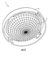
- FIGURE 2 is a perspective view from the bottom side of the lighting apparatus shown in FIGURE 1 ;
- FIGURE 3 is an "X-ray" view from the bottom side of the lighting apparatus shown in FIGURE 3 ;
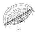
- FIGURE 4 is a cross-sectional perspective view from the top side of the lighting apparatus shown in FIGURE 1 ;
- FIGURE 5 is a cross-sectional perspective view from the bottom side of the lighting apparatus shown in FIGURE 1 ;
- FIGURE 6 is a cross-sectional view of the lighting apparatus shown in FIGURE 1 ;
- FIGURE 7 is a cross-sectional view of a known heat pipe (from http://en.wikipedia.org/wiki /Image:Heat_Pipe_Mechanism.png);
- FIGURE 8 is a perspective view of a lighting apparatus according to another aspect of the present invention.
- FIGURE 9 is a perspective view from the bottom side of the lighting apparatus shown in FIGURE 8 ;
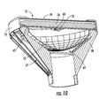
- FIGURE 10 is a cross-sectional perspective view of the lighting apparatus shown in FIGURE 8 ;
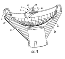
- FIGURE 11 is another cross-sectional perspective view of the lighting apparatus shown in FIGURE 8 ;
- FIGURE 12 is an exploded perspective view of the lighting apparatus shown in FIGURE 8 ;
- FIGURE 13 is an exploded cross-sectional view of the lighting apparatus shown in FIGURE 8 ;
- FIGURE 14 is a perspective view of a heat conducting body (cladded heat pipe) with an LED coupled directly onto according to an aspect of the present invention
- FIGURE 15 is a perspective view of a heat conducting body (non-cladded heat pipe) with an LED coupled directly onto according to another aspect of the present invention
- FIGURE 16 is a perspective view of a lighting apparatus (which includes an S-shaped heat conducting body) according to another aspect of the present invention.
- FIGURE 17 is a side view of the lighting apparatus shown in FIGURE 16 ;
- FIGURE 18 is a cross-sectional perspective view of the lighting apparatus shown in FIGURE 16 ;
- FIGURE 19 is an exploded perspective view of the top rim and a heat sink mounting apparatus (which includes a metal cladding, an S-shaped heat conducting body, a mounting platform, a mounting plate, and an LED) of the lighting apparatus shown in FIGURE 16 ; and
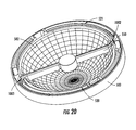
- FIGURE 20 is a perspective view from the top side (without a glass cover) of the lighting apparatus shown in FIGURE 16 .
- a lighting apparatus 1 has a reflector 4 which is coupled to a top rim 3, wherein the top rim 3 is coupled to a heat conducting body 2.
- the heat conducting body 2 contains a heat pipe 8 which is cladded by a cladding 9, and a mounting platform 5 located on one side of the heat conducting body 2 facing opposite the front side of the reflector 4.
- an LED 6 is coupled to a metal core printed circuit board (“PCB”) 7 which is then coupled to the mounting platform 5.
- PCB metal core printed circuit board
- the mounting platform 5 is shaped (which, in this aspect of the present invention, is circular) in such a manner that it provides increased non-glare protection from the LED relative to existing lighting apparatuses.
- the LED 6 is located above at or near a central optical axis 300 of the reflector 4, and is positioned so that light emitted from the LED 6 is substantially or entirely directed to the front side of the reflector 4; thereby, as shown in FIGURE 6 , allowing the reflector 4 to collect and colliminate the light emitted from LED 6, and reflect the colliminated light away from the reflector 4 and past LED 6 and the heat conducting body 2.
- the heat conducting body 2 intercepts very little of the exiting reflected, colliminated light from reflector 4 due to its flat, narrow construction. As shown in FIGURE 3 , the flat, narrow construction of the heat conducting body 2 creates a small cross-section 10 to the exiting reflected, colliminated light from reflector 4.
- the heat generated from the LED 6 travels the following heat path through the lighting apparatus: metal core PCB 7, mounting platform 5, cladding 9, heat pipe 8, cladding 9, and then top rim 3 and reflector 4.
- the heat generated from the LED 6 can also travel through metal core PCB 7, mounting platform 5, cladding 9, heat pipe 8, and then top rim 3 and reflector 4.
- the top rim 3 and reflector 4 act as heat sinks.
- the lighting apparatus 50 contains a reflector 53 which is coupled to a top rim 52, wherein the top rim 52 is coupled to a heat conducting body 51.
- the heat conducting body 51 contains a heat pipe 56 which is cladded by a cladding 59, and a mounting platform 54 located on one side of the heat conducting body 51 facing opposite the reflector 53.
- the LED 55 as shown in FIGURE 11 , is coupled to a metal core PCB 60 which is then coupled to the mounting platform 54.
- This aspect of the present invention includes a main housing 57 which has one or more heat dissipating fins 58 for maximizing surface area; thereby, increasing its heat dissipation capacity.
- the top rim 52, reflector 53, and the main housing 57 act as heat sinks, with the main housing 57 acting as the primary heat sink.
- the main housing 57 is coupled to a reflector edge 63.
- the size of air gap 62 can vary depending on the size of the reflector 53.
- the heat generated from the LED 55 travels a heat path which includes travelling through metal core PCB 60, mounting platform 54, cladding 59, heat pipe 56, cladding 59, and then top rim 52, reflector 53 and main housing 57.
- the heat can also travel through metal core PCB 60, mounting platform 54, cladding 59, heat pipe 56, and then top rim 52, reflector 53 and main housing 57.
- the lighting apparatus 500 includes a main housing 501; a reflector 502 having a front side and a rear side; a top rim 503 coupled to the main housing 501; a heat conducting body 1000 which is positioned on the front side of the reflector 502 and coupled to the top rim 503; an LED 504 being positioned facing directly at the front side of the reflector 502 so that light emitted from the LED 504 is substantially or entirely directed to the front side of the reflector 502.
- the heat conducting body 1000 is substantially S-shaped and includes a middle portion 1001 that is bar-shaped or substantially bar-shaped; and curved wing portions 1002 and 1003 which extend from each end of the middle portion 1001.
- curved wing portions 1002 and 1002 are coupled to the top rim 503, wherein the top rim 503 has slots 520 and 521 which permit the curved wing portions 1002 and 1003 to fit within the slots 520, 521, respectively; thereby, permitting coupling of the heat conducting body 1000 and the top rim 503.
- the heat conducting body 1000 and the top rim 503 can also be coupled via soldering, thermal epoxy or any other techniques known in the art which are used to couple the heat conducting body 1000 to the top rim 503.
- the heat conducting body 1000 includes a mounting platform 530 which is positioned near or at the central optical axis of the reflector 502, and a mounting plate 531 coupled between the mounting platform 530 and LED 504.
- the heat conducting body 1000 also includes a heat pipe is located at the middle portion 1001 and/or one or both of the curved wing portions 1002 and 1003.
- a metal cladding 550 can be coupled to the heat conducting body 1000.
- a substantial portion of the middle portion 1001 of the heat conducting body 1000 is coupled to the metal cladding 550.
- the metal cladding 550 can be used to secure and direct electrical cable or wires which extends from the top rim 503 to the LED 504 along the middle portion 1001 of the heat conducting body 1000, and is made of a thermally-conductive material, such as stainless steel, aluminum, copper or any other high-heat conductive material.
- the present invention can include a glass cover 800 which is coupled to the top rim 503 and a cap rim 509.
- the glass cover 800 protects at least the reflector 502, the heat conducting body 1000, the mounting platform 530, the mounting plate 531 and LED 504 from environmental hazards, such as water and dust.
- the glass cover can also be used in conjunction with the aspects of the present invention set forth in FIGURES 1-6 and 8-13 .
- the present invention can also include a plastic housing 700 that is coupled to the bottom end of the main housing 501, and a lamp base 701 (e.g., an E26 lamp base, a GU10 lamp base, an E27 lamp base) that is coupled to the plastic housing 700.
- a lamp base 701 e.g., an E26 lamp base, a GU10 lamp base, an E27 lamp base
- the heat conducting body 2, 51 contain a heat pipe 8, 56 which is cladded by a cladding 9, 59, and a mounting platform 5, 54 located on one side of the heat conducting body 2, 51 facing opposite the reflector 4, 53.
- the cladding 9, 59 can be made of a thermally-conductive material such as aluminum, copper, graphite or zinc, and can include a mounting platform 5, 54.
- the cladding 9, 59 can be used to increase structural strength of the heat pipe 8, 56, assist in transferring and spreading the heat from the LED 6, 55 to the heat pipe, and assist in the transferring and spreading the heat from the heat pipe 8, 56 to the heat sinks, such as top rim 3, 52, reflector 4, 53 and main housing 57.
- the heat conducting body 1000 can be coupled to a metal cladding 550.
- Metal cladding 550 covers a substantial portion of the middle portion 1001 of the heat conducting body 1000, and is used for aesthetic purposes, securing electric cable or wires between heat conducting body 1000 and metal cladding 550, and/or directing such electric cable or wires to the LED 504.
- the metal cladding 550 can be made of thermally-conductive material, such as stainless steel, aluminum, copper or any other high-heat conductive material.
- the LED 91 can be directly affixed onto a heat conducting body 90 (via the mounting platform 92 of cladding 93).
- FIGURE 15 shows a heat conducting body 100 wherein an LED 103 is coupled onto a mounting platform 102, which is, in turn, directly coupled to a heat pipe 101.
- the mounting platform 102 can be cylindrically-shaped, and can partially or completely encase at least the center of the heat pipe 101.
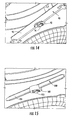
- the heat pipe (such as heat pipe 8, 56, 101) can be made of porous copper incorporating a large number cavities filled with pure water. As shown in FIGURE 7 , water within the heat pipe evaporates to vapor as it absorbs thermal energy from a heat source. See 400 in FIGURE 7 . The vaporized water then migrates along the vapor cavity to cooler sections of the heat pipe. See 401 in FIGURE 7 . There, the vapor quickly cools and condenses back to fluid, and the fluid is absorbed by the wick, releasing thermal energy. See 402 in FIGURE 7 . The fluid then returns along the inner cavities to the heated sections (See 403 in FIGURE 7 ), and repeats the heat pipe thermal cycle described above.
- the heat pipe use the above-described mechanism to transmit thermal energy from the LED to heat sinks, such as the top rim 3, 52, reflector 4, 53, and main housing 57, 501.
- the heat pipe can be flattened (in a cross-section direction) into a thin strip in order to minimize light absorption.
- Another aspect of the present invention includes a heat conducting body with one or more heat pipes.
- each heat pipe is connected to a center hub (like a spoke on a wheel) positioned near or at the central optical axis of a reflector.
- the center hub acts as a mounting platform for one or more LEDs, and is made of thermally-conductive material such as aluminum, copper or any other high-heat conductive material.
- the heat conducting body extends up to or near the central axis of a reflector and being coupled to the top rim at only one connection point (such as connection point 900 or 901 for FIGURE 1 , or connection point 910 or 911 for FIGURE 8 ).
- connection point 900 or 901 for FIGURE 1 or connection point 910 or 911 for FIGURE 8
- the heat conducting body does not form a chord to or a diameter of the top rim of FIGURES 1 and 8 .
- the heat conducting body includes a mounting platform with an LED directly coupled thereto, or an LED coupled to a metal core PCB or a mounting plate, which is then coupled to the mounting platform.
- This alternative aspect of the present invention reduces light blockage caused by the heat conducting body and improves lens efficiency, while promoting heat dissipation and anti-glare.
- the mounting platform 5, 54, 102, 530 are made of a thermally-conductive material such as aluminum, copper or any other high-heat conductive material. Also, as mentioned above, the mounting platform provides increased non-glare protection from the LED relative to existing light apparatuses. In the present invention, the possibility of direct glare from the LED is eliminated (or at least mitigated) since (1) the LED is coupled onto the mounting platform and positioned facing directly at the reflector so as that light emitted from the LED is substantially or entirely directed to the reflector, and (2) the mounting platform is shaped (e.g., circular) in a manner which prevents a direct view of the LED at any viewing angle.
- the reflector 4, 53, 502 are made of a thermally-conductive material such as aluminum, and act as a heat sink.
- the reflector 4, 53, 502 can be made of a non-thermally-conductive material such as plastic.
- light emitted from the LED 6 is substantially or entirely directed toward the reflector 4, wherein the reflector 4 collimates the light emitted from the LED 6 into a light beam and reflects the light beam with a particular beam angle.
- the beam angle can range from 2 to 60 Full Width Half Maximum ("FWHM") degree.
- the reflector 4 of the present invention is designed to collect substantially or entirely the light emitted from the LED 6, and redirect the light in a manner which eliminates (or at least mitigates) luminance of the present invention within a direct glare zone (i.e. , approximately 45 to 85 degree with respect to vertical).
- the reflector 4, 53, 502 can take a variety of shapes to achieve various light beam patterns. It can be shaped in any conic section (e.g., hyperbola, ellipse or parabola), used singularly or in various combinations, in two-dimension or three-dimensional shapes.
- conic section e.g., hyperbola, ellipse or parabola
- An LED can be an LED module with one or more chips.
- the LED can be a high-powered LED.
- One or more LEDs can be used in the present invention.
- the LED 6, 55, 504 are coupled to a metal core PCB 7, 60 or a mounting plate 531.
- the LED 91, 103 are coupled to the mounting platform 92 and 102.
- the LED can be soldered onto a metal core PCB, mounting plate, or mounting platform. Thermal paste, thermal grease, soldering, reflow soldering or any other soldering materials or techniques known in the art can be used to couple the LED onto the metal core PCB, mounting plate, or mounting platform.
- the present invention includes a metal core PCB (see metal core PCB 7, 60 shown in FIGURES 3 and 12 ).
- the metal core PCB includes LED circuitry, and acts as a heat-transporting medium.
- the metal core PCB comprises a base metal plate (copper or aluminum, which is approximately 0.8 to 3mm thick), a dielectric layer (laminated on top of the base metal plate, which is approximately 0.1 mm thick), and a copper circuit track (printed on top of dielectric layer, which is approximately 0.05 to 0.2 mm thick).
- a metal core PCB is not included in the present invention in order to further reduce thermal resistance; thereby, reducing LED junction temperature and increasing maximum LED power.
- a mounting plate 531 is used, wherein the mounting plate 531 being coupled to the LED 504 and to the mounting platform 530.
- the mounting plate is made a thermally-conductive material such as copper or any other high-heat conductive material, and approximately 0.8 to 3mm thick. Mechanical techniques (such as screws) known in the art are used to couple the mounting plate to the mounting platform, and a thermal grease or paste with high thermal conductivity can be used between the mounting plate and mounting platform.
- the top rim 3, 52, 503 are made of a thermally-conductive material, such as aluminum, copper or zinc or any other high-heat conductive material.
- the top rim 3 acts as a primary heat sink (for example, see FIGURE 1 ), or, like top rim 52, 503, as a secondary heat sink (for example, see FIGURES 8 and 18 ).
- the present invention includes a cap rim 509 which helps secures the glass cover 800 to the top rim 503.
- the main housing 57, 501 are made of a thermally-conductive material, such as aluminum, copper, zinc or any other high-heat conductive material.
- the main housing 57, 501 act as a primary heat sink (for example, see FIGURES 8 and 17 ).
- the main housing 57, 501 can have one or more fins 58 or 570 and/or take a conical-like shape to increase its surface area in order to increase its heat dissipation capacity.
- the main housing 57, 501 can be substantially frustoconical in shape.
- the main housing can also be cylindrical or cubical in shape.
- one end of the main housing 57, 501 are coupled with a plastic housing 700, the plastic housing 700 coupled to a lamp base 701 (e.g., an E26 lamp base, a GU10 lamp base, an E27 lamp base, a GU24 lamp base).
- the plastic housing 700 contains main circuit boards, and electrically insulate such main circuit boards from the main housing 57, 501.
- main housing can be utilized in conjunction with the aspect of the present invention set forth in FIGURES 1-6
- plastic housing 700 and lamp base 701 can be utilized with the aspects of the present invention shown in FIGURES 1-6 and FIGURES 8-13 .
Claims (17)
- Beleuchtungsvorrichtung (1) aufweisend:ein Hauptgehäuse (57; 501);einen Reflektor (4; 502), der innerhalb des Hauptgehäuses angeordnet ist, wobei der Reflektor eine Vorderseite und eine Rückseite aufweist;einen oberen Rand (3; 503), der an ein Ende des Hauptgehäuses thermisch gekoppelt ist;einen wärmeleitenden Körper (2; 1000), welcher der Vorderseite des Reflektors zugewandt angeordnet ist;mindestens eine lichtemittierende Diode (6), die thermisch an den wärmeleitenden Körper gekoppelt ist, wobei die mindestens eine lichtemittierende Diode der Vorderseite des Reflektors direkt zugewandt angeordnet ist, sodass von der mindestens einen lichtemittierenden Diode emittiertes Licht zur Vorderseite des Reflektors geführt ist; dadurch gekennzeichnet, dassder wärmeleitende Körper ein mit dem oberen Rand thermisch verbundenes Wärmerohr (8; 101) aufweist; undder wärmeleitende Körper (1000) im Wesentlichen S-förmig ist und einen mittleren Bereich (1001) aufweist, der stabförmig ist, und gekrümmte Flügelbereiche (1002, 1003), die sich vom mittleren Bereich erstrecken, wobei jeder der gebogenen Flügelbereiche an den oberen Rand (503) gekoppelt ist.
- Beleuchtungsvorrichtung gemäß Anspruch 1, wobei der wärmeleitende Körper einen Pfad für Wärme bereitstellt, um von der mindestens einen lichtemittierenden Diode zum oberen Rand zu fließen.
- Beleuchtungsvorrichtung gemäß Anspruch 1, wobei der Reflektor eine zentrale optische Achse (300) hat; und die Beleuchtungsvorrichtung weiterhin aufweist:eine Befestigungsplattform (5), die mit dem wärmeleitenden Körper verbunden ist und nahe oder an der optischen Achse des Reflektors positioniert und an die mindestens eine lichtemittierende Diode thermisch gekoppelt ist.
- Beleuchtungsvorrichtung gemäß Anspruch 3, wobei die Befestigungsplattform aus Kupfer oder Aluminium hergestellt ist.
- Beleuchtungsvorrichtung gemäß Anspruch 1, weiterhin aufweisend eine Metallhülle (550), die zumindest an einen substanziellen Bereich des wärmeleitenden Körpers gekoppelt ist.
- Beleuchtungsvorrichtung gemäß Anspruch 5, wobei die Metallhülle aus Edelstahl, Aluminium oder Kupfer hergestellt ist.
- Beleuchtungsvorrichtung gemäß Anspruch 1, wobei der Reflektor die Gestalt einer Hyperbel, Ellipse oder Parabel aufweist.
- Beleuchtungsvorrichtung gemäß Anspruch 1, wobei der obere Rand kreisförmig ist und aus einem wärmeleitenden Material hergestellt ist.
- Beleuchtungsvorrichtung gemäß Anspruch 1, wobei das Hauptgehäuse im Wesentlichen kegelstumpfförmiger, zylindrischer oder würfelförmiger Gestalt ist und aus einem wärmeleitenden Material hergestellt ist.
- Beleuchtungsvorrichtung gemäß Anspruch 1, wobei das Hauptgehäuse eine oder mehrere Kühlrippen (58; 570) aufweist.
- Beleuchtungsvorrichtung gemäß Anspruch 9, weiterhin aufweisend:ein Kunststoffgehäuse (700), gekoppelt an das Hauptgehäuse; undeinen Lampensockel (701), gekoppelt an das Kunststoffgehäuse.
- Beleuchtungsvorrichtung gemäß Anspruch 11, wobei der Lampensockel ein E26-Lampensockel, ein GU10-Lampensockel oder ein E27-Lampensockel ist.
- Beleuchtungsvorrichtung gemäß Anspruch 1, weiterhin aufweisend:eine Befestigungsplatte (531), die an die mindestens eine lichtemittierende Diode thermisch gekoppelt ist; und eine Befestigungsplattform (530), die an die Befestigungsplatte und den wärmeleitenden Körper thermisch gekoppelt ist.
- Beleuchtungsvorrichtung gemäß Anspruch 13, wobei die Befestigungsplatte aus Kupfer oder Aluminium hergestellt ist.
- Beleuchtungsvorrichtung gemäß Anspruch 1, weiterhin aufweisend eine Glasabdeckung (800), die an den oberen Rand (503) gekoppelt ist, wobei die Glasabdeckung zumindest den Reflektor (502), den wärmleitenden Körper (1000) und die mindestens eine lichtemittierende Diode von der externen Umgebung abdeckt.
- Beleuchtungsvorrichtung gemäß Anspruch 1,
wobei das Hauptgehäuse (57; 501) eine im Allgemeinen kegelstumpfförmige Gestalt hat;
wobei der Reflektor ein konisch geformter Reflektor mit einer zentralen optischen Achse (300) ist;
wobei der obere Rand kreisförmig ist;
wobei das Wärmerohr im Wesentlichen S-förmig ist und der Vorderseite des konisch geformten Reflektors zugewandt positioniert ist, wobei das im Wesentlichen S-förmige Wärmerohr einen mittleren Bereich (1001) aufweist, der eine Befestigungsplattform (530) aufweist, die sich an oder nahe der zentralen optischen Achse des konisch geformten Reflektors befindet, und zwei gekrümmte Flügelbereiche (1002, 2003), wobei die gekrümmten Flügelbereiche jeweils mit jedem Ende des mittleren Teilbereiches verbunden sind und an den oberen Rand gekoppelt sind; und
wobei die mindestens eine lichtemittierende Diode thermisch an die Befestigungsplattform gekoppelt ist. - Beleuchtungsvorrichtung gemäß Anspruch 16, weiterhin aufweisend eine Metallkern-Leiterplatte, die an die mindestens eine lichtemittierende Diode und die Befestigungsplattform gekoppelt ist.
Priority Applications (1)
| Application Number | Priority Date | Filing Date | Title |
|---|---|---|---|
| PL09749365T PL2276973T3 (pl) | 2008-05-23 | 2009-05-21 | Nieoślepiające odblaskowe urządzenie oświetleniowe led z mocowaniem radiatora |
Applications Claiming Priority (4)
| Application Number | Priority Date | Filing Date | Title |
|---|---|---|---|
| US5585808P | 2008-05-23 | 2008-05-23 | |
| US5728908P | 2008-05-30 | 2008-05-30 | |
| US11820208P | 2008-11-26 | 2008-11-26 | |
| PCT/CA2009/000689 WO2009140761A1 (en) | 2008-05-23 | 2009-05-21 | Non-glare reflective led lighting apparatus with heat sink mounting |
Publications (3)
| Publication Number | Publication Date |
|---|---|
| EP2276973A1 EP2276973A1 (de) | 2011-01-26 |
| EP2276973A4 EP2276973A4 (de) | 2011-05-18 |
| EP2276973B1 true EP2276973B1 (de) | 2012-11-21 |
Family
ID=41339695
Family Applications (1)
| Application Number | Title | Priority Date | Filing Date |
|---|---|---|---|
| EP09749365A Active EP2276973B1 (de) | 2008-05-23 | 2009-05-21 | Nicht blendende reflektive led-beleuchtungsvorrichtung mit kühlkörperhalterung |
Country Status (16)
| Country | Link |
|---|---|
| US (1) | US9322517B2 (de) |
| EP (1) | EP2276973B1 (de) |
| JP (1) | JP5492874B2 (de) |
| KR (1) | KR101249609B1 (de) |
| CN (1) | CN102037279B (de) |
| AU (1) | AU2009250290B2 (de) |
| CA (1) | CA2723901C (de) |
| DK (1) | DK2276973T3 (de) |
| ES (1) | ES2399387T3 (de) |
| HK (2) | HK1151845A1 (de) |
| MX (1) | MX2010012184A (de) |
| PL (1) | PL2276973T3 (de) |
| SG (2) | SG171624A1 (de) |
| TW (1) | TWI381138B (de) |
| WO (1) | WO2009140761A1 (de) |
| ZA (1) | ZA201008043B (de) |
Families Citing this family (70)
| Publication number | Priority date | Publication date | Assignee | Title |
|---|---|---|---|---|
| US7597453B2 (en) * | 2004-01-14 | 2009-10-06 | Simon Jerome H | Luminaires using multiple quasi-point sources for unified radially distributed illumination |
| US9234646B2 (en) | 2008-05-23 | 2016-01-12 | Huizhou Light Engine Ltd. | Non-glare reflective LED lighting apparatus with heat sink mounting |
| CN102037279B (zh) | 2008-05-23 | 2013-06-26 | 惠州元晖光电股份有限公司 | 具有散热固定装置的无眩光反射led照明装置 |
| US7946735B2 (en) * | 2008-08-22 | 2011-05-24 | Joseph Chou | LED lighting apparatus having heat dissipating frame |
| US8858032B2 (en) * | 2008-10-24 | 2014-10-14 | Cree, Inc. | Lighting device, heat transfer structure and heat transfer element |
| KR20120093230A (ko) * | 2009-09-25 | 2012-08-22 | 크리, 인코포레이티드 | 열 소산 요소를 갖는 조명 장치 |
| US8540402B2 (en) | 2010-05-23 | 2013-09-24 | RAB Lighting Inc. | LED housing with heat transfer sink |
| US10883702B2 (en) | 2010-08-31 | 2021-01-05 | Ideal Industries Lighting Llc | Troffer-style fixture |
| JP5536602B2 (ja) * | 2010-09-29 | 2014-07-02 | パナソニック株式会社 | ランプ |
| JP5681971B2 (ja) * | 2010-09-29 | 2015-03-11 | パナソニックIpマネジメント株式会社 | ランプ |
| EP2625458A4 (de) | 2010-10-04 | 2014-04-23 | Huizhou Light Engine Ltd | Lichtquelle mit flachem modul |
| IT1402883B1 (it) * | 2010-11-22 | 2013-09-27 | Reggiani Illuminazione | Dispositivo di illuminazione a led con mezzi di ancoraggio. |
| US9822951B2 (en) | 2010-12-06 | 2017-11-21 | Cree, Inc. | LED retrofit lens for fluorescent tube |
| US10309627B2 (en) | 2012-11-08 | 2019-06-04 | Cree, Inc. | Light fixture retrofit kit with integrated light bar |
| US9581312B2 (en) | 2010-12-06 | 2017-02-28 | Cree, Inc. | LED light fixtures having elongated prismatic lenses |
| US9494293B2 (en) | 2010-12-06 | 2016-11-15 | Cree, Inc. | Troffer-style optical assembly |
| CN102679292A (zh) * | 2011-03-11 | 2012-09-19 | 马士科技有限公司 | 用于灯具的散热装置及包括该散热装置的led灯具 |
| CN102691948B (zh) * | 2011-03-23 | 2016-04-20 | 欧司朗股份有限公司 | 能够多方向调节照射角度的筒灯 |
| EP2702315B8 (de) * | 2011-04-29 | 2018-08-22 | Lumileds Holding B.V. | Led-beleuchtungsvorrichtung mit unterer wärmeableitungsstruktur |
| GB2486134B8 (en) | 2011-07-04 | 2014-02-05 | Metrolight Ltd | Light emitting diode 'LED' lighting fixture |
| US10823347B2 (en) | 2011-07-24 | 2020-11-03 | Ideal Industries Lighting Llc | Modular indirect suspended/ceiling mount fixture |
| US8704262B2 (en) * | 2011-08-11 | 2014-04-22 | Goldeneye, Inc. | Solid state light sources with common luminescent and heat dissipating surfaces |
| US9857034B2 (en) * | 2011-10-27 | 2018-01-02 | Lg Electronics Inc. | Ultra slim collimator for light emitting diode |
| CN103104816A (zh) * | 2011-11-09 | 2013-05-15 | 苏州市协众精密工具有限公司 | 一种led灯具 |
| US9423117B2 (en) * | 2011-12-30 | 2016-08-23 | Cree, Inc. | LED fixture with heat pipe |
| US10544925B2 (en) | 2012-01-06 | 2020-01-28 | Ideal Industries Lighting Llc | Mounting system for retrofit light installation into existing light fixtures |
| US9777897B2 (en) | 2012-02-07 | 2017-10-03 | Cree, Inc. | Multiple panel troffer-style fixture |
| US8905575B2 (en) | 2012-02-09 | 2014-12-09 | Cree, Inc. | Troffer-style lighting fixture with specular reflector |
| WO2013123570A1 (en) * | 2012-02-21 | 2013-08-29 | Huizhou Light Engine Ltd. | Non-glare reflective led lighting apparatus with heat sink mounting |
| US9310038B2 (en) | 2012-03-23 | 2016-04-12 | Cree, Inc. | LED fixture with integrated driver circuitry |
| US10054274B2 (en) | 2012-03-23 | 2018-08-21 | Cree, Inc. | Direct attach ceiling-mounted solid state downlights |
| US9360185B2 (en) | 2012-04-09 | 2016-06-07 | Cree, Inc. | Variable beam angle directional lighting fixture assembly |
| US9874322B2 (en) | 2012-04-10 | 2018-01-23 | Cree, Inc. | Lensed troffer-style light fixture |
| US9285099B2 (en) | 2012-04-23 | 2016-03-15 | Cree, Inc. | Parabolic troffer-style light fixture |
| EP2856014B1 (de) * | 2012-06-04 | 2018-03-28 | Philips Lighting Holding B.V. | Beleuchtungsvorrichtung mit einem optischen reflektor, leuchte mit einer solchen beleuchtungsvorrichtung und verfahren zur herstellung eines kompakten optischen reflektors |
| US8931929B2 (en) | 2012-07-09 | 2015-01-13 | Cree, Inc. | Light emitting diode primary optic for beam shaping |
| US20140063792A1 (en) * | 2012-08-30 | 2014-03-06 | Juno Manufacturing, LLC | Hyperbolic Ceiling-Reflector For Directional Light Sources |
| US9482396B2 (en) | 2012-11-08 | 2016-11-01 | Cree, Inc. | Integrated linear light engine |
| US9441818B2 (en) | 2012-11-08 | 2016-09-13 | Cree, Inc. | Uplight with suspended fixture |
| US9494304B2 (en) | 2012-11-08 | 2016-11-15 | Cree, Inc. | Recessed light fixture retrofit kit |
| US9423104B2 (en) | 2013-03-14 | 2016-08-23 | Cree, Inc. | Linear solid state lighting fixture with asymmetric light distribution |
| US10648643B2 (en) | 2013-03-14 | 2020-05-12 | Ideal Industries Lighting Llc | Door frame troffer |
| US9052075B2 (en) | 2013-03-15 | 2015-06-09 | Cree, Inc. | Standardized troffer fixture |
| KR101452217B1 (ko) * | 2013-05-22 | 2014-10-23 | 대양전기공업 주식회사 | 서치라이트용 엘이디 탐조등 |
| CN103335225B (zh) * | 2013-06-08 | 2015-07-08 | 深圳市蓝科电子有限公司 | 一种具有多兼容性led灯体 |
| KR101425581B1 (ko) * | 2013-07-26 | 2014-08-04 | 주식회사 한국비코 | 엘이디 조명기구 |
| USD786471S1 (en) | 2013-09-06 | 2017-05-09 | Cree, Inc. | Troffer-style light fixture |
| CN103775877A (zh) * | 2014-01-24 | 2014-05-07 | 李鹤荣 | 一种反射型led照明灯 |
| USD807556S1 (en) | 2014-02-02 | 2018-01-09 | Cree Hong Kong Limited | Troffer-style fixture |
| USD772465S1 (en) | 2014-02-02 | 2016-11-22 | Cree Hong Kong Limited | Troffer-style fixture |
| USD749768S1 (en) | 2014-02-06 | 2016-02-16 | Cree, Inc. | Troffer-style light fixture with sensors |
| US10527225B2 (en) | 2014-03-25 | 2020-01-07 | Ideal Industries, Llc | Frame and lens upgrade kits for lighting fixtures |
| US20160010809A1 (en) * | 2014-03-28 | 2016-01-14 | Carlotta Francesca Isolina Maria de BEVILACQUA | Lighting apparatus |
| KR20150134871A (ko) * | 2014-05-23 | 2015-12-02 | 에스엘 주식회사 | 차량용 램프 |
| CN103982822A (zh) * | 2014-05-28 | 2014-08-13 | 昆山生态屋建筑技术有限公司 | 一种导热柱上设置有风扇的射灯 |
| CN105202382A (zh) * | 2014-06-27 | 2015-12-30 | 安徽兆利光电科技有限公司 | 一种新型led灯 |
| TWI595189B (zh) * | 2014-09-02 | 2017-08-11 | Huan-Chiu Chou | 內反射燈具 |
| ES2563651B1 (es) * | 2014-09-15 | 2016-12-21 | Jaume GIMENO GIRÓ | Módulo soporte de Led |
| RU2017125355A (ru) | 2014-12-18 | 2019-01-23 | Армстронг Уорлд Индастриз, Инк | Интегрированная потолочная и осветительная система |
| US10690334B2 (en) | 2015-02-25 | 2020-06-23 | CAO Group, LLC | Operatory lights and replacement bulbs for operatory lights |
| TWI517998B (zh) * | 2015-04-21 | 2016-01-21 | 久鐵工業股份有限公司 | 車燈結構 |
| US10012354B2 (en) | 2015-06-26 | 2018-07-03 | Cree, Inc. | Adjustable retrofit LED troffer |
| JP6710534B2 (ja) * | 2016-02-17 | 2020-06-17 | トキコーポレーション株式会社 | 発光装置 |
| CN105627120B (zh) * | 2016-03-18 | 2018-09-18 | 深圳星标科技股份有限公司 | 反射罩式led灯具 |
| KR20180097877A (ko) | 2017-02-24 | 2018-09-03 | 엘지이노텍 주식회사 | 발광모듈 및 이를 구비한 조명 시스템 |
| US10544915B2 (en) | 2017-04-27 | 2020-01-28 | Valeo North America, Inc. | Vehicle lamp assembly having an improved heat sink with light shield |
| CN107461716B (zh) * | 2017-09-05 | 2023-09-19 | 华格照明科技(上海)有限公司 | 一种光学反射器 |
| US11480313B2 (en) * | 2019-05-17 | 2022-10-25 | North American Lighting, Inc. | Vehicle lamp |
| CN110985947B (zh) * | 2019-12-30 | 2020-09-08 | 广州兰天电子科技有限公司 | 一种led聚光灯组装方法 |
| CN111140787B (zh) * | 2019-12-30 | 2020-08-11 | 广州兰天电子科技有限公司 | 一种全反射led聚光灯 |
Family Cites Families (51)
| Publication number | Priority date | Publication date | Assignee | Title |
|---|---|---|---|---|
| US4503360A (en) * | 1982-07-26 | 1985-03-05 | North American Philips Lighting Corporation | Compact fluorescent lamp unit having segregated air-cooling means |
| GB2161912B (en) * | 1984-07-19 | 1987-10-28 | Shimizu Construction Co Ltd | Illumination apparatus |
| US4837667A (en) * | 1986-10-03 | 1989-06-06 | Tobias Grau | Lighting system with lamps arranged between two low-voltage conductors |
| US4897771A (en) * | 1987-11-24 | 1990-01-30 | Lumitex, Inc. | Reflector and light system |
| JPH0646002Y2 (ja) * | 1988-04-26 | 1994-11-24 | 株式会社小糸製作所 | 車輌用灯具 |
| DE4100411A1 (de) * | 1991-01-09 | 1992-07-16 | Bosch Gmbh Robert | Scheinwerfer fuer kraftfahrzeuge |
| SE513881C2 (sv) * | 1994-01-10 | 2000-11-20 | Boule Medical Ab | Förfarande och anordning för analys av vätskeprover |
| JPH0896605A (ja) | 1994-09-28 | 1996-04-12 | Koito Mfg Co Ltd | 車輌用前照灯 |
| JP4047411B2 (ja) | 1997-01-31 | 2008-02-13 | 株式会社鈴木用品製作所 | 作業灯の灯体防振方法、および同防振構造 |
| EP1146280B1 (de) * | 2000-04-12 | 2009-12-09 | WERMA Holding GmbH + Co. KG | Signalgerät |
| JP2002168575A (ja) * | 2000-12-05 | 2002-06-14 | Furukawa Electric Co Ltd:The | ヒートパイプ |
| JP4214749B2 (ja) | 2002-10-02 | 2009-01-28 | 日亜化学工業株式会社 | 照明装置 |
| US7011431B2 (en) * | 2002-04-23 | 2006-03-14 | Nichia Corporation | Lighting apparatus |
| US7048412B2 (en) | 2002-06-10 | 2006-05-23 | Lumileds Lighting U.S., Llc | Axial LED source |
| JP4352686B2 (ja) | 2002-11-22 | 2009-10-28 | 日亜化学工業株式会社 | 反射型発光装置 |
| EP1631769B1 (de) * | 2003-06-10 | 2010-09-22 | Illumination Management Solutions, Inc. | Verbesserte led-taschenlampe |
| US6976769B2 (en) * | 2003-06-11 | 2005-12-20 | Cool Options, Inc. | Light-emitting diode reflector assembly having a heat pipe |
| TWI225713B (en) * | 2003-09-26 | 2004-12-21 | Bin-Juine Huang | Illumination apparatus of light emitting diodes and method of heat dissipation thereof |
| JP4236608B2 (ja) * | 2003-10-31 | 2009-03-11 | シャープ株式会社 | リフレクタ、光源装置、及び投射型表示装置 |
| US7144135B2 (en) * | 2003-11-26 | 2006-12-05 | Philips Lumileds Lighting Company, Llc | LED lamp heat sink |
| US7246921B2 (en) | 2004-02-03 | 2007-07-24 | Illumitech, Inc. | Back-reflecting LED light source |
| US7131760B2 (en) * | 2004-02-20 | 2006-11-07 | Gelcore Llc | LED luminaire with thermally conductive support |
| JP4778503B2 (ja) * | 2004-03-05 | 2011-09-21 | オスラム ゲゼルシャフト ミット ベシュレンクテル ハフツング | ランプ |
| US7742225B2 (en) * | 2004-06-14 | 2010-06-22 | Hewlett-Packard Development Company, L.P. | Bandpass reflector with heat removal |
| TWI263008B (en) * | 2004-06-30 | 2006-10-01 | Ind Tech Res Inst | LED lamp |
| CN1722484A (zh) | 2004-07-16 | 2006-01-18 | 奥斯兰姆施尔凡尼亚公司 | 用于发光二极管的管座装置 |
| CA2580114A1 (en) | 2004-09-16 | 2006-03-30 | Magna International Inc. | Thermal management system for solid state automotive lighting |
| DE102004046764A1 (de) | 2004-09-24 | 2006-04-06 | Daimlerchrysler Ag | Fahrzeugscheinwerfer |
| JP2006202612A (ja) | 2005-01-20 | 2006-08-03 | Momo Alliance Co Ltd | 発光装置及び照明装置 |
| US7565925B2 (en) * | 2005-06-24 | 2009-07-28 | Fu Zhun Precision Industry (Shen Zhen) Co., Ltd. | Heat dissipation device |
| US7446412B2 (en) * | 2006-03-28 | 2008-11-04 | Intel Corporation | Heat sink design using clad metal |
| US7549772B2 (en) * | 2006-03-31 | 2009-06-23 | Pyroswift Holding Co., Limited | LED lamp conducting structure with plate-type heat pipe |
| US7789534B2 (en) * | 2006-03-31 | 2010-09-07 | Pyroswift Holding Co., Limited. | LED lamp with heat dissipation mechanism and multiple light emitting faces |
| JP2009539233A (ja) * | 2006-05-30 | 2009-11-12 | ネオバルブ テクノロジーズ,インコーポレイテッド | 高出力、高放熱効率を備えた発光ダイオード照明装置 |
| US7708452B2 (en) | 2006-06-08 | 2010-05-04 | Lighting Science Group Corporation | Lighting apparatus including flexible power supply |
| US7494248B2 (en) * | 2006-07-05 | 2009-02-24 | Jaffe Limited | Heat-dissipating structure for LED lamp |
| US8292463B2 (en) | 2006-07-28 | 2012-10-23 | Koninklijke Philips Electronics N.V. | Illumination module with similar heat and light propagation directions |
| JP2008051389A (ja) | 2006-08-24 | 2008-03-06 | Asahi Kasei Fibers Corp | ヒートパイプ型伝熱装置 |
| EP1898148A1 (de) * | 2006-09-05 | 2008-03-12 | Attila A. Bruckner | Rasterblendenbefestigung für Beleuchtungseinrichtungen |
| JP4726872B2 (ja) * | 2006-09-27 | 2011-07-20 | シーシーエス株式会社 | 反射型照明装置 |
| KR101317429B1 (ko) | 2007-01-31 | 2013-10-10 | 잘만테크 주식회사 | 히트파이프를 이용한 냉각장치를 구비한 led조명 조립체 |
| WO2009007905A2 (en) | 2007-07-11 | 2009-01-15 | Koninklijke Philips Electronics N.V. | Heat pipe |
| CN102037279B (zh) | 2008-05-23 | 2013-06-26 | 惠州元晖光电股份有限公司 | 具有散热固定装置的无眩光反射led照明装置 |
| TWI407043B (zh) * | 2008-11-04 | 2013-09-01 | Advanced Optoelectronic Tech | 發光二極體光源模組及其光學引擎 |
| CN101865369B (zh) | 2009-04-16 | 2014-04-30 | 富准精密工业(深圳)有限公司 | 发光二极管灯具 |
| TW201038868A (en) | 2009-04-24 | 2010-11-01 | Foxconn Tech Co Ltd | Light emitting diode lamp |
| TW201038870A (en) | 2009-04-24 | 2010-11-01 | Foxconn Tech Co Ltd | Light emitting diode lamp |
| RU2573424C2 (ru) | 2009-06-25 | 2016-01-20 | Конинклейке Филипс Электроникс Н.В. | Теплорегулирующее устройство |
| CN102087004B (zh) | 2009-12-03 | 2014-06-11 | 马士科技有限公司 | 发光二极管灯和其中的反光杯 |
| EP2397753B1 (de) | 2010-06-15 | 2013-05-29 | Kitagawa Holdings, LLC | LED-Lampe und Wärmesenke davon mit einem Wundenheizrohr |
| DE102010030296B4 (de) | 2010-06-21 | 2012-11-22 | Osram Ag | Lampe mit konkavem Reflektor und einem Vorsprung für mindestens eine Lichtquelle |
-
2009
- 2009-05-21 CN CN2009801187101A patent/CN102037279B/zh not_active Expired - Fee Related
- 2009-05-21 ES ES09749365T patent/ES2399387T3/es active Active
- 2009-05-21 MX MX2010012184A patent/MX2010012184A/es active IP Right Grant
- 2009-05-21 US US12/470,332 patent/US9322517B2/en not_active Expired - Fee Related
- 2009-05-21 SG SG201102971-7A patent/SG171624A1/en unknown
- 2009-05-21 CA CA2723901A patent/CA2723901C/en not_active Expired - Fee Related
- 2009-05-21 EP EP09749365A patent/EP2276973B1/de active Active
- 2009-05-21 DK DK09749365.4T patent/DK2276973T3/da active
- 2009-05-21 AU AU2009250290A patent/AU2009250290B2/en not_active Ceased
- 2009-05-21 WO PCT/CA2009/000689 patent/WO2009140761A1/en active Application Filing
- 2009-05-21 SG SG201102970-9A patent/SG171623A1/en unknown
- 2009-05-21 KR KR1020107025624A patent/KR101249609B1/ko not_active IP Right Cessation
- 2009-05-21 JP JP2011509828A patent/JP5492874B2/ja not_active Expired - Fee Related
- 2009-05-21 TW TW098116869A patent/TWI381138B/zh not_active IP Right Cessation
- 2009-05-21 PL PL09749365T patent/PL2276973T3/pl unknown
-
2010
- 2010-11-10 ZA ZA2010/08043A patent/ZA201008043B/en unknown
-
2011
- 2011-06-09 HK HK11105853.2A patent/HK1151845A1/xx not_active IP Right Cessation
- 2011-06-15 HK HK11106123.4A patent/HK1152096A1/xx not_active IP Right Cessation
Also Published As
| Publication number | Publication date |
|---|---|
| WO2009140761A1 (en) | 2009-11-26 |
| TW201007085A (en) | 2010-02-16 |
| TWI381138B (zh) | 2013-01-01 |
| PL2276973T3 (pl) | 2013-04-30 |
| HK1151845A1 (en) | 2012-02-10 |
| AU2009250290B2 (en) | 2011-10-13 |
| US9322517B2 (en) | 2016-04-26 |
| EP2276973A4 (de) | 2011-05-18 |
| JP5492874B2 (ja) | 2014-05-14 |
| EP2276973A1 (de) | 2011-01-26 |
| KR101249609B1 (ko) | 2013-04-01 |
| CA2723901C (en) | 2014-07-22 |
| HK1152096A1 (en) | 2012-02-17 |
| CN102037279A (zh) | 2011-04-27 |
| KR20110002862A (ko) | 2011-01-10 |
| JP2011521460A (ja) | 2011-07-21 |
| AU2009250290A1 (en) | 2009-11-26 |
| ZA201008043B (en) | 2011-09-28 |
| CA2723901A1 (en) | 2009-11-26 |
| SG171623A1 (en) | 2011-06-29 |
| DK2276973T3 (da) | 2013-01-14 |
| ES2399387T3 (es) | 2013-04-01 |
| SG171624A1 (en) | 2011-06-29 |
| MX2010012184A (es) | 2010-12-21 |
| AU2009250290A8 (en) | 2010-12-16 |
| CN102037279B (zh) | 2013-06-26 |
| US20090290349A1 (en) | 2009-11-26 |
Similar Documents
| Publication | Publication Date | Title |
|---|---|---|
| EP2276973B1 (de) | Nicht blendende reflektive led-beleuchtungsvorrichtung mit kühlkörperhalterung | |
| JP5331571B2 (ja) | Led反射ランプ | |
| RU2547811C2 (ru) | Универсальное осветительное устройство с твердотельными источниками света | |
| US7575354B2 (en) | Thermal management system for solid state automotive lighting | |
| US9157598B2 (en) | Heat managing device | |
| TWI407043B (zh) | 發光二極體光源模組及其光學引擎 | |
| US9068701B2 (en) | Lamp structure with remote LED light source | |
| CN104583669A (zh) | 具有led和改进的反射准直器的照明装置 | |
| CN211853588U (zh) | 灯具 | |
| WO2013123570A1 (en) | Non-glare reflective led lighting apparatus with heat sink mounting | |
| US9234646B2 (en) | Non-glare reflective LED lighting apparatus with heat sink mounting | |
| JP2008135260A (ja) | 車両用前照灯 | |
| TW201300690A (zh) | 照明器的led解決方案 | |
| US9206975B2 (en) | Non-glare reflective LED lighting apparatus with heat sink mounting | |
| US9255673B2 (en) | LED bulb having an adjustable light-distribution profile | |
| WO2016192124A1 (zh) | 投光灯 | |
| CN212840766U (zh) | 一种led照明设备 | |
| TWI331199B (en) | Led lamp having heat dissipation structure | |
| CN110762438A (zh) | 一种快速散热的led灯 |
Legal Events
| Date | Code | Title | Description |
|---|---|---|---|
| PUAI | Public reference made under article 153(3) epc to a published international application that has entered the european phase |
Free format text: ORIGINAL CODE: 0009012 |
|
| 17P | Request for examination filed |
Effective date: 20101109 |
|
| AK | Designated contracting states |
Kind code of ref document: A1 Designated state(s): AT BE BG CH CY CZ DE DK EE ES FI FR GB GR HR HU IE IS IT LI LT LU LV MC MK MT NL NO PL PT RO SE SI SK TR |
|
| AX | Request for extension of the european patent |
Extension state: AL BA RS |
|
| RAP1 | Party data changed (applicant data changed or rights of an application transferred) |
Owner name: HUIZHOU LIGHT ENGINE LTD. |
|
| A4 | Supplementary search report drawn up and despatched |
Effective date: 20110414 |
|
| DAX | Request for extension of the european patent (deleted) | ||
| 17Q | First examination report despatched |
Effective date: 20111028 |
|
| REG | Reference to a national code |
Ref country code: HK Ref legal event code: DE Ref document number: 1152096 Country of ref document: HK |
|
| RIC1 | Information provided on ipc code assigned before grant |
Ipc: F21V 29/00 20060101AFI20120522BHEP |
|
| GRAP | Despatch of communication of intention to grant a patent |
Free format text: ORIGINAL CODE: EPIDOSNIGR1 |
|
| GRAS | Grant fee paid |
Free format text: ORIGINAL CODE: EPIDOSNIGR3 |
|
| GRAA | (expected) grant |
Free format text: ORIGINAL CODE: 0009210 |
|
| AK | Designated contracting states |
Kind code of ref document: B1 Designated state(s): AT BE BG CH CY CZ DE DK EE ES FI FR GB GR HR HU IE IS IT LI LT LU LV MC MK MT NL NO PL PT RO SE SI SK TR |
|
| REG | Reference to a national code |
Ref country code: GB Ref legal event code: FG4D |
|
| REG | Reference to a national code |
Ref country code: CH Ref legal event code: EP |
|
| REG | Reference to a national code |
Ref country code: AT Ref legal event code: REF Ref document number: 585283 Country of ref document: AT Kind code of ref document: T Effective date: 20121215 |
|
| REG | Reference to a national code |
Ref country code: IE Ref legal event code: FG4D |
|
| REG | Reference to a national code |
Ref country code: DK Ref legal event code: T3 |
|
| REG | Reference to a national code |
Ref country code: DE Ref legal event code: R096 Ref document number: 602009011387 Country of ref document: DE Effective date: 20130117 |
|
| REG | Reference to a national code |
Ref country code: SE Ref legal event code: TRGR |
|
| REG | Reference to a national code |
Ref country code: NL Ref legal event code: T3 |
|
| REG | Reference to a national code |
Ref country code: ES Ref legal event code: FG2A Ref document number: 2399387 Country of ref document: ES Kind code of ref document: T3 Effective date: 20130401 |
|
| REG | Reference to a national code |
Ref country code: NO Ref legal event code: T2 Effective date: 20121121 |
|
| REG | Reference to a national code |
Ref country code: LT Ref legal event code: MG4D |
|
| PG25 | Lapsed in a contracting state [announced via postgrant information from national office to epo] |
Ref country code: LT Free format text: LAPSE BECAUSE OF FAILURE TO SUBMIT A TRANSLATION OF THE DESCRIPTION OR TO PAY THE FEE WITHIN THE PRESCRIBED TIME-LIMIT Effective date: 20121121 |
|
| REG | Reference to a national code |
Ref country code: PL Ref legal event code: T3 |
|
| PG25 | Lapsed in a contracting state [announced via postgrant information from national office to epo] |
Ref country code: GR Free format text: LAPSE BECAUSE OF FAILURE TO SUBMIT A TRANSLATION OF THE DESCRIPTION OR TO PAY THE FEE WITHIN THE PRESCRIBED TIME-LIMIT Effective date: 20130222 Ref country code: LV Free format text: LAPSE BECAUSE OF FAILURE TO SUBMIT A TRANSLATION OF THE DESCRIPTION OR TO PAY THE FEE WITHIN THE PRESCRIBED TIME-LIMIT Effective date: 20121121 Ref country code: SI Free format text: LAPSE BECAUSE OF FAILURE TO SUBMIT A TRANSLATION OF THE DESCRIPTION OR TO PAY THE FEE WITHIN THE PRESCRIBED TIME-LIMIT Effective date: 20121121 Ref country code: PT Free format text: LAPSE BECAUSE OF FAILURE TO SUBMIT A TRANSLATION OF THE DESCRIPTION OR TO PAY THE FEE WITHIN THE PRESCRIBED TIME-LIMIT Effective date: 20130321 |
|
| REG | Reference to a national code |
Ref country code: HK Ref legal event code: GR Ref document number: 1152096 Country of ref document: HK |
|
| PG25 | Lapsed in a contracting state [announced via postgrant information from national office to epo] |
Ref country code: BG Free format text: LAPSE BECAUSE OF FAILURE TO SUBMIT A TRANSLATION OF THE DESCRIPTION OR TO PAY THE FEE WITHIN THE PRESCRIBED TIME-LIMIT Effective date: 20130221 Ref country code: CZ Free format text: LAPSE BECAUSE OF FAILURE TO SUBMIT A TRANSLATION OF THE DESCRIPTION OR TO PAY THE FEE WITHIN THE PRESCRIBED TIME-LIMIT Effective date: 20121121 Ref country code: SK Free format text: LAPSE BECAUSE OF FAILURE TO SUBMIT A TRANSLATION OF THE DESCRIPTION OR TO PAY THE FEE WITHIN THE PRESCRIBED TIME-LIMIT Effective date: 20121121 Ref country code: EE Free format text: LAPSE BECAUSE OF FAILURE TO SUBMIT A TRANSLATION OF THE DESCRIPTION OR TO PAY THE FEE WITHIN THE PRESCRIBED TIME-LIMIT Effective date: 20121121 |
|
| PG25 | Lapsed in a contracting state [announced via postgrant information from national office to epo] |
Ref country code: RO Free format text: LAPSE BECAUSE OF FAILURE TO SUBMIT A TRANSLATION OF THE DESCRIPTION OR TO PAY THE FEE WITHIN THE PRESCRIBED TIME-LIMIT Effective date: 20121121 |
|
| PLBE | No opposition filed within time limit |
Free format text: ORIGINAL CODE: 0009261 |
|
| STAA | Information on the status of an ep patent application or granted ep patent |
Free format text: STATUS: NO OPPOSITION FILED WITHIN TIME LIMIT |
|
| 26N | No opposition filed |
Effective date: 20130822 |
|
| PG25 | Lapsed in a contracting state [announced via postgrant information from national office to epo] |
Ref country code: HR Free format text: LAPSE BECAUSE OF FAILURE TO SUBMIT A TRANSLATION OF THE DESCRIPTION OR TO PAY THE FEE WITHIN THE PRESCRIBED TIME-LIMIT Effective date: 20121121 |
|
| REG | Reference to a national code |
Ref country code: DE Ref legal event code: R097 Ref document number: 602009011387 Country of ref document: DE Effective date: 20130822 |
|
| PG25 | Lapsed in a contracting state [announced via postgrant information from national office to epo] |
Ref country code: MC Free format text: LAPSE BECAUSE OF FAILURE TO SUBMIT A TRANSLATION OF THE DESCRIPTION OR TO PAY THE FEE WITHIN THE PRESCRIBED TIME-LIMIT Effective date: 20121121 |
|
| REG | Reference to a national code |
Ref country code: IE Ref legal event code: MM4A |
|
| PG25 | Lapsed in a contracting state [announced via postgrant information from national office to epo] |
Ref country code: IE Free format text: LAPSE BECAUSE OF NON-PAYMENT OF DUE FEES Effective date: 20130521 |
|
| PG25 | Lapsed in a contracting state [announced via postgrant information from national office to epo] |
Ref country code: MT Free format text: LAPSE BECAUSE OF FAILURE TO SUBMIT A TRANSLATION OF THE DESCRIPTION OR TO PAY THE FEE WITHIN THE PRESCRIBED TIME-LIMIT Effective date: 20121121 |
|
| PG25 | Lapsed in a contracting state [announced via postgrant information from national office to epo] |
Ref country code: CY Free format text: LAPSE BECAUSE OF FAILURE TO SUBMIT A TRANSLATION OF THE DESCRIPTION OR TO PAY THE FEE WITHIN THE PRESCRIBED TIME-LIMIT Effective date: 20121121 |
|
| PG25 | Lapsed in a contracting state [announced via postgrant information from national office to epo] |
Ref country code: LU Free format text: LAPSE BECAUSE OF NON-PAYMENT OF DUE FEES Effective date: 20130521 Ref country code: MK Free format text: LAPSE BECAUSE OF FAILURE TO SUBMIT A TRANSLATION OF THE DESCRIPTION OR TO PAY THE FEE WITHIN THE PRESCRIBED TIME-LIMIT Effective date: 20121121 Ref country code: HU Free format text: LAPSE BECAUSE OF FAILURE TO SUBMIT A TRANSLATION OF THE DESCRIPTION OR TO PAY THE FEE WITHIN THE PRESCRIBED TIME-LIMIT; INVALID AB INITIO Effective date: 20090521 |
|
| PGFP | Annual fee paid to national office [announced via postgrant information from national office to epo] |
Ref country code: DK Payment date: 20150512 Year of fee payment: 7 Ref country code: FI Payment date: 20150512 Year of fee payment: 7 Ref country code: TR Payment date: 20150505 Year of fee payment: 7 Ref country code: NO Payment date: 20150511 Year of fee payment: 7 |
|
| PGFP | Annual fee paid to national office [announced via postgrant information from national office to epo] |
Ref country code: AT Payment date: 20150427 Year of fee payment: 7 Ref country code: PL Payment date: 20150401 Year of fee payment: 7 |
|
| REG | Reference to a national code |
Ref country code: FR Ref legal event code: PLFP Year of fee payment: 8 |
|
| PGFP | Annual fee paid to national office [announced via postgrant information from national office to epo] |
Ref country code: BE Payment date: 20160324 Year of fee payment: 8 |
|
| PG25 | Lapsed in a contracting state [announced via postgrant information from national office to epo] |
Ref country code: IS Free format text: LAPSE BECAUSE OF FAILURE TO SUBMIT A TRANSLATION OF THE DESCRIPTION OR TO PAY THE FEE WITHIN THE PRESCRIBED TIME-LIMIT Effective date: 20121121 |
|
| PGFP | Annual fee paid to national office [announced via postgrant information from national office to epo] |
Ref country code: CH Payment date: 20160511 Year of fee payment: 8 Ref country code: ES Payment date: 20160412 Year of fee payment: 8 |
|
| PGFP | Annual fee paid to national office [announced via postgrant information from national office to epo] |
Ref country code: IT Payment date: 20160524 Year of fee payment: 8 Ref country code: SE Payment date: 20160511 Year of fee payment: 8 |
|
| REG | Reference to a national code |
Ref country code: NO Ref legal event code: MMEP |
|
| REG | Reference to a national code |
Ref country code: DK Ref legal event code: EBP Effective date: 20160531 |
|
| REG | Reference to a national code |
Ref country code: AT Ref legal event code: MM01 Ref document number: 585283 Country of ref document: AT Kind code of ref document: T Effective date: 20160521 |
|
| PG25 | Lapsed in a contracting state [announced via postgrant information from national office to epo] |
Ref country code: NO Free format text: LAPSE BECAUSE OF NON-PAYMENT OF DUE FEES Effective date: 20160531 Ref country code: FI Free format text: LAPSE BECAUSE OF NON-PAYMENT OF DUE FEES Effective date: 20160521 |
|
| PG25 | Lapsed in a contracting state [announced via postgrant information from national office to epo] |
Ref country code: AT Free format text: LAPSE BECAUSE OF NON-PAYMENT OF DUE FEES Effective date: 20160521 |
|
| REG | Reference to a national code |
Ref country code: FR Ref legal event code: PLFP Year of fee payment: 9 |
|
| PG25 | Lapsed in a contracting state [announced via postgrant information from national office to epo] |
Ref country code: DK Free format text: LAPSE BECAUSE OF NON-PAYMENT OF DUE FEES Effective date: 20160531 |
|
| PG25 | Lapsed in a contracting state [announced via postgrant information from national office to epo] |
Ref country code: PL Free format text: LAPSE BECAUSE OF NON-PAYMENT OF DUE FEES Effective date: 20160521 |
|
| REG | Reference to a national code |
Ref country code: CH Ref legal event code: PL |
|
| REG | Reference to a national code |
Ref country code: SE Ref legal event code: EUG |
|
| PG25 | Lapsed in a contracting state [announced via postgrant information from national office to epo] |
Ref country code: CH Free format text: LAPSE BECAUSE OF NON-PAYMENT OF DUE FEES Effective date: 20170531 Ref country code: LI Free format text: LAPSE BECAUSE OF NON-PAYMENT OF DUE FEES Effective date: 20170531 Ref country code: SE Free format text: LAPSE BECAUSE OF NON-PAYMENT OF DUE FEES Effective date: 20170522 |
|
| REG | Reference to a national code |
Ref country code: BE Ref legal event code: MM Effective date: 20170531 |
|
| REG | Reference to a national code |
Ref country code: FR Ref legal event code: PLFP Year of fee payment: 10 |
|
| PG25 | Lapsed in a contracting state [announced via postgrant information from national office to epo] |
Ref country code: IT Free format text: LAPSE BECAUSE OF NON-PAYMENT OF DUE FEES Effective date: 20170521 |
|
| REG | Reference to a national code |
Ref country code: ES Ref legal event code: FD2A Effective date: 20180704 |
|
| PG25 | Lapsed in a contracting state [announced via postgrant information from national office to epo] |
Ref country code: ES Free format text: LAPSE BECAUSE OF NON-PAYMENT OF DUE FEES Effective date: 20170522 |
|
| PG25 | Lapsed in a contracting state [announced via postgrant information from national office to epo] |
Ref country code: BE Free format text: LAPSE BECAUSE OF NON-PAYMENT OF DUE FEES Effective date: 20170531 |
|
| PGFP | Annual fee paid to national office [announced via postgrant information from national office to epo] |
Ref country code: FR Payment date: 20190510 Year of fee payment: 11 |
|
| PGFP | Annual fee paid to national office [announced via postgrant information from national office to epo] |
Ref country code: GB Payment date: 20190515 Year of fee payment: 11 |
|
| GBPC | Gb: european patent ceased through non-payment of renewal fee |
Effective date: 20200521 |
|
| PG25 | Lapsed in a contracting state [announced via postgrant information from national office to epo] |
Ref country code: GB Free format text: LAPSE BECAUSE OF NON-PAYMENT OF DUE FEES Effective date: 20200521 Ref country code: FR Free format text: LAPSE BECAUSE OF NON-PAYMENT OF DUE FEES Effective date: 20200531 |
|
| PG25 | Lapsed in a contracting state [announced via postgrant information from national office to epo] |
Ref country code: TR Free format text: LAPSE BECAUSE OF NON-PAYMENT OF DUE FEES Effective date: 20160521 |
|
| PGFP | Annual fee paid to national office [announced via postgrant information from national office to epo] |
Ref country code: NL Payment date: 20230525 Year of fee payment: 15 Ref country code: DE Payment date: 20230516 Year of fee payment: 15 |