EP2276182A2 - Systèmes et procédés permettant de caracteriser des lignes de transmission dans un environnement DSL à ondes porteuses multiples - Google Patents
Systèmes et procédés permettant de caracteriser des lignes de transmission dans un environnement DSL à ondes porteuses multiples Download PDFInfo
- Publication number
- EP2276182A2 EP2276182A2 EP20100011985 EP10011985A EP2276182A2 EP 2276182 A2 EP2276182 A2 EP 2276182A2 EP 20100011985 EP20100011985 EP 20100011985 EP 10011985 A EP10011985 A EP 10011985A EP 2276182 A2 EP2276182 A2 EP 2276182A2
- Authority
- EP
- European Patent Office
- Prior art keywords
- diagnostic
- message
- modem
- information
- test information
- Prior art date
- Legal status (The legal status is an assumption and is not a legal conclusion. Google has not performed a legal analysis and makes no representation as to the accuracy of the status listed.)
- Granted
Links
Images

Classifications
-
- H—ELECTRICITY
- H04—ELECTRIC COMMUNICATION TECHNIQUE
- H04M—TELEPHONIC COMMUNICATION
- H04M3/00—Automatic or semi-automatic exchanges
- H04M3/22—Arrangements for supervision, monitoring or testing
- H04M3/26—Arrangements for supervision, monitoring or testing with means for applying test signals or for measuring
- H04M3/28—Automatic routine testing ; Fault testing; Installation testing; Test methods, test equipment or test arrangements therefor
- H04M3/30—Automatic routine testing ; Fault testing; Installation testing; Test methods, test equipment or test arrangements therefor for subscriber's lines, for the local loop
- H04M3/302—Automatic routine testing ; Fault testing; Installation testing; Test methods, test equipment or test arrangements therefor for subscriber's lines, for the local loop using modulation techniques for copper pairs
- H04M3/304—Automatic routine testing ; Fault testing; Installation testing; Test methods, test equipment or test arrangements therefor for subscriber's lines, for the local loop using modulation techniques for copper pairs and using xDSL modems
-
- H—ELECTRICITY
- H04—ELECTRIC COMMUNICATION TECHNIQUE
- H04B—TRANSMISSION
- H04B3/00—Line transmission systems
- H04B3/02—Details
- H04B3/46—Monitoring; Testing
-
- H—ELECTRICITY
- H04—ELECTRIC COMMUNICATION TECHNIQUE
- H04L—TRANSMISSION OF DIGITAL INFORMATION, e.g. TELEGRAPHIC COMMUNICATION
- H04L1/00—Arrangements for detecting or preventing errors in the information received
- H04L1/0001—Systems modifying transmission characteristics according to link quality, e.g. power backoff
-
- H—ELECTRICITY
- H04—ELECTRIC COMMUNICATION TECHNIQUE
- H04L—TRANSMISSION OF DIGITAL INFORMATION, e.g. TELEGRAPHIC COMMUNICATION
- H04L1/00—Arrangements for detecting or preventing errors in the information received
- H04L1/004—Arrangements for detecting or preventing errors in the information received by using forward error control
- H04L1/0056—Systems characterized by the type of code used
- H04L1/0061—Error detection codes
-
- H—ELECTRICITY
- H04—ELECTRIC COMMUNICATION TECHNIQUE
- H04L—TRANSMISSION OF DIGITAL INFORMATION, e.g. TELEGRAPHIC COMMUNICATION
- H04L1/00—Arrangements for detecting or preventing errors in the information received
- H04L1/08—Arrangements for detecting or preventing errors in the information received by repeating transmission, e.g. Verdan system
-
- H—ELECTRICITY
- H04—ELECTRIC COMMUNICATION TECHNIQUE
- H04L—TRANSMISSION OF DIGITAL INFORMATION, e.g. TELEGRAPHIC COMMUNICATION
- H04L1/00—Arrangements for detecting or preventing errors in the information received
- H04L1/12—Arrangements for detecting or preventing errors in the information received by using return channel
- H04L1/16—Arrangements for detecting or preventing errors in the information received by using return channel in which the return channel carries supervisory signals, e.g. repetition request signals
- H04L1/18—Automatic repetition systems, e.g. Van Duuren systems
-
- H—ELECTRICITY
- H04—ELECTRIC COMMUNICATION TECHNIQUE
- H04L—TRANSMISSION OF DIGITAL INFORMATION, e.g. TELEGRAPHIC COMMUNICATION
- H04L1/00—Arrangements for detecting or preventing errors in the information received
- H04L1/24—Testing correct operation
-
- H—ELECTRICITY
- H04—ELECTRIC COMMUNICATION TECHNIQUE
- H04L—TRANSMISSION OF DIGITAL INFORMATION, e.g. TELEGRAPHIC COMMUNICATION
- H04L1/00—Arrangements for detecting or preventing errors in the information received
- H04L1/24—Testing correct operation
- H04L1/245—Testing correct operation by using the properties of transmission codes
-
- H—ELECTRICITY
- H04—ELECTRIC COMMUNICATION TECHNIQUE
- H04L—TRANSMISSION OF DIGITAL INFORMATION, e.g. TELEGRAPHIC COMMUNICATION
- H04L27/00—Modulated-carrier systems
- H04L27/26—Systems using multi-frequency codes
- H04L27/2601—Multicarrier modulation systems
-
- H—ELECTRICITY
- H04—ELECTRIC COMMUNICATION TECHNIQUE
- H04L—TRANSMISSION OF DIGITAL INFORMATION, e.g. TELEGRAPHIC COMMUNICATION
- H04L27/00—Modulated-carrier systems
- H04L27/32—Carrier systems characterised by combinations of two or more of the types covered by groups H04L27/02, H04L27/10, H04L27/18 or H04L27/26
- H04L27/34—Amplitude- and phase-modulated carrier systems, e.g. quadrature-amplitude modulated carrier systems
- H04L27/345—Modifications of the signal space to allow the transmission of additional information
- H04L27/3461—Modifications of the signal space to allow the transmission of additional information in order to transmit a subchannel
-
- H—ELECTRICITY
- H04—ELECTRIC COMMUNICATION TECHNIQUE
- H04L—TRANSMISSION OF DIGITAL INFORMATION, e.g. TELEGRAPHIC COMMUNICATION
- H04L5/00—Arrangements affording multiple use of the transmission path
- H04L5/14—Two-way operation using the same type of signal, i.e. duplex
- H04L5/1438—Negotiation of transmission parameters prior to communication
-
- H—ELECTRICITY
- H04—ELECTRIC COMMUNICATION TECHNIQUE
- H04M—TELEPHONIC COMMUNICATION
- H04M3/00—Automatic or semi-automatic exchanges
- H04M3/22—Arrangements for supervision, monitoring or testing
- H04M3/2209—Arrangements for supervision, monitoring or testing for lines also used for data transmission
-
- H—ELECTRICITY
- H04—ELECTRIC COMMUNICATION TECHNIQUE
- H04M—TELEPHONIC COMMUNICATION
- H04M3/00—Automatic or semi-automatic exchanges
- H04M3/22—Arrangements for supervision, monitoring or testing
- H04M3/2227—Quality of service monitoring
-
- H—ELECTRICITY
- H04—ELECTRIC COMMUNICATION TECHNIQUE
- H04M—TELEPHONIC COMMUNICATION
- H04M3/00—Automatic or semi-automatic exchanges
- H04M3/22—Arrangements for supervision, monitoring or testing
- H04M3/26—Arrangements for supervision, monitoring or testing with means for applying test signals or for measuring
- H04M3/28—Automatic routine testing ; Fault testing; Installation testing; Test methods, test equipment or test arrangements therefor
- H04M3/30—Automatic routine testing ; Fault testing; Installation testing; Test methods, test equipment or test arrangements therefor for subscriber's lines, for the local loop
Definitions
- This invention relates to test and diagnostic information.
- this invention relates to a robust system and method for communicating diagnostic information.
- the exchange of diagnostic and test information between transceivers in a telecommunications environment is an important part of a telecommunications, such as an ADSL, deployment.
- a telecommunications such as an ADSL
- communications over a local subscriber loop between a central office and a subscriber premises is accomplished by modulating the data to be transmitted onto a multiplicity of discrete frequency carriers which are summed together and then transmitted over the subscriber loop, Individually, the carriers form discrete, nonoverlapping communication subchannels of limited bandwidth. Collectively, the carriers form what is effectively a broadband communications channel. At the receiver end, the carriers are demodulated and the data recovered.
- DSL systems experience disturbances from other data services on adjacent phone lines, such as, for example, ADSL, HDSL, ISDN, T1, or the like. These disturbances may commence after the subject ADSL service is already initiated and, since DSL for internet access is envisioned as an always-on service, the effect of these disturbances must be ameliorated by the subject ADSL transceiver.
- the systems and methods of this invention are directed toward reliably exchanging diagnostic and test information between transceivers over a digital subscriber line in the presence of voice communications and/or other disturbances.
- the systems and methods of the invention will hereafter refer to the transceivers generically as modems.
- One such modem is typically located at a customer premises such as a home or business and is "downstream" from a central office with which it communicates.
- the other modem is typically located at the central office and is "upstream" from the customer premises.
- the modems are often referred to as "ATU-R" ("ADSL transceiver unit, remote,” i.e., located at the customer premises) and “ATU-C” (“ADSL transceiver unit, central office” i.e., located at the central office).
- ATU-R ADSL transceiver unit, remote
- ATU-C ADSL transceiver unit, central office
- Each modem includes a transmitter section for transmitting data and a receiver section for receiving data, and is of the discrete multitone type, i.e., the modem transmits data over a multiplicity of subchannels of limited bandwidth.
- the upstream or ATU-C modem transmits data to the downstream or ATU-R modem over a first set of subchannel, which are usually the higher-frequency subchannels, and receives data from the downstream or ATU-R modem over a second, usually smaller, set of subchannels, commonly the lower-frequency subchannels.
- the diagnostic and test information is communicated using a signaling mechanism that has a very high immunity to noise and/or other disturbances and can therefore operate effectively even in the case where the modems could not actually establish an acceptable connection in their normal operational mode.
- the modems For example, if the ATU-C and/or ATU-R modem fail to complete an initialization sequence, and are thus unable to enter a normal steady state communications mode, where the diagnostic and test information would normally be exchanged, the modems according to the systems and methods of this invention enter a robust diagnostic link mode.
- the diagnostic link mode can be entered automatically or manually, for example, at the direction of a user.
- the modems exchange the diagnostic and test information that is, for example, used by a technician to determine the cause of a failure without the technician having to physically visit, i.e., a truckroll to, the remote site to collect data.
- the diagnostic and test information can include, for example, but is not limited to, signal to noise ratio information, equalizer information, programmable gain setting information, bit allocation information, transmitted and received power information, margin information, status and rate information, telephone line condition information, such as the length of the line, the number and location of bridged taps, a wire gauge, or the like, or any other known or later developed diagnostic or test information that may be appropriate for the particular communications environment.
- the exchanged diagnostic and test information can be directed toward specific limitations of the modems, to information relating to the modem installation and deployment environment, or to other diagnostic and test information that can, for example, be determined as needed which may aid in evaluating the cause of a specific failure or problem.
- the diagnostic and test information can include the loop length and bridged tap length estimations as discussed in copending Attorney Docket No. 081513-000003, filed herewith and incorporated herein by reference in its entirety.
- an exemplary embodiment of the invention illustrates the use of the diagnostic link mode in the communication of diagnostic information from the remote terminal (RT) transceiver, e.g., ATU-R, to the central office (CO) transceiver, e.g., ATU-C.
- RT remote terminal
- CO central office
- Transmission of information from the remote terminal to the central office is important since a typical ADSL service provider is located in the central office and would therefore benefit from the ability to determine problems at the remote terminal without a truckroll.
- the systems and the methods of this invention will work equally well in communications from the central office to the remote terminal.
- the systems and methods of this invention complete a portion of the normal modem initialization before entering into the diagnostic link mode.
- the systems and methods of this invention can enter the diagnostic link mode manually, for example, at the direction of a technician or a user after completing a portion of initialization.
- the systems and methods of this invention can enter the diagnostic link mode automatically based on, for example, a bit rate failure, a forward error correction or a CRC error during showtime, e.g., the normal steady state transmission mode, or the like.
- the transition into the diagnostic link mode is accomplished by transmitting a message from the CO modem to the RT modem indicating that the modems are to enter into the diagnostic link mode, as opposed to transitioning into the normal steady state data transmission mode.
- the transition into the diagnostic link mode is accomplished by transmitting a message from the RT modem to the CO modem indicating that the modems are to enter into the diagnostic link mode as opposed to transitioning into the normal steady state data transmission mode.
- the transition signal uses an ADSL state transition to transition from a standard ADSL state to a diagnostic link mode state.
- the RT modem sends diagnostic and test information in the form of a collection of information bits to the CO modem that are, for example, modulated by using one bit per DTM symbol modulation, as is used in the C-Ratesl message in the ITU and ANSI ADSL standards, where the symbol may or may not include a cyclic prefix.
- Other exemplary modulation techniques include Differential Phase Shift Keying (DPSK) on a subset or all the carriers, as specified in, for example, ITU standard G.994.1, higher order QAM modulation (>1 bit per carrier), or the like.
- DPSK Differential Phase Shift Keying
- a bit with value 0 is mapped to the REVERB1 signal and a bit with a value of 1 mapped to a SEGUE1 signal.
- the REVERB and SEGUE1 signals are defined in the ITU and ANSI ADSL standards.
- the REVERB1 signal is generated by modulating all of the carriers in the multicarrier system with a known pseudo-random sequence thus generating a wideband modulated signal.
- the SEGUE1 signal is generated from a carrier by 180 degree phase reversal of the REVERB1 signal.
- Table 1 Exemplary Message Variables Data Sent in the Diag Link Train Type ADSL Standard Chip Type Vendor ID Code Version Average Reverb Received Signal Programmable gain amplifier (PGA) Gain - Training Programmable gain amplifier PGA Gain - Showtime Filter Present during Idle Channel Calculation Average Idle Channel Noise Signal to Noise during Training Signal to Noise during Showtime Bits and Gains Data Rate Framing Mode Margin Reed-Solomon Coding Gain QAM Usage Frequency Domain Equalizer (FDQ) Coefficients Gain Scale Time domain equalizer (TDQ) Coefficients Digital Echo Canceller (DEC) Coefficients
- FDQ Frequency Domain Equalizer
- TDQ Gain Scale Time domain equalizer
- DEC Digital Echo Canceller
- Table 1 shows an example of a data message that can be sent by the RT to the CO during the diagnostic link mode.
- the RT modem sends 23 different data variables to the CO.
- Each data variable contains different items of diagnostic and test information that are used to analyze the condition of the link.
- the variables may contain more than one item of data.
- the Average Reverb Signal contains the power levels per tone, up to, for example, 256 entries, detected during the ADSL Reverb signal.
- the PGA Gain - Training is a single entry, denoting the gain in dB at the receiver during the ADSL training.
- variables that represent the type of diagnostic and test information that are used to analyze the condition of the link are sent from the RT modem to the CO modem. These variables can be, for example, arrays with different lengths depending on, for example, information in the initiate diagnostic mode message.
- the systems and methods of this invention can be tailored to contain many different diagnostic and test information variables.
- the system is fully configurable, allowing subsets of data to be sent and additional data variables to be added in the future. Therefore, the message length can be increased or decreased, and diagnostic and test information customized, to support more or less variables as, for example, hardware, the environment and/or the telecommunications equipment dictates.
- variables transmitted from the modem being tested to the receiving modem can be any combination of variables which allow for transmission of test and/or diagnostic information.
- Fig. 1 illustrates an exemplary embodiment of the additional modem components associated with the diagnostic link mode.
- the diagnostic link system 100 comprises a central office modem 200 and a remote terminal modem 300.
- the central office modem 200 comprises, in addition to the standard ATU-C components, a CRC checker 210, a diagnostic device 220, and a diagnostic information monitoring device 230.
- the remote terminal modem 300 comprises, in addition to the standard components associated with an ATU-R, a message determination device 310, a power control device 320, a diagnostic device 330 and a diagnostic information storage device 340.
- the central office modem 200 and the remote terminal model 300 are also connected, via link 5, to a splitter 10 for a phone switch 20, and a splitter 30 for a phone 40.
- the ATU-R can operate without a splitter, e.g., splitterless, as specified in ITU standard G.992.2 (G.lite) or with an in-line filter in series with the phone 40.
- the remote terminal modem 300 can also be connected to, for example, one or more user terminals 60.
- the central office modem 200 can be connected to one or more distributed networks 50, via link 5, which may or may not also be connected to one or more other distributed networks.
- Fig. 1 shows the diagnostic link system 100 for an embodiment in which the remote terminal modem 300 is communicating test and diagnostic information to the central office 200
- the various components of the diagnostic link system can be rearranged such that the diagnostic and test information can be forwarded from the central office 200 to the remote terminal modem 300, or, alternatively, such that both modems can send and receive diagnostic and/or test information.
- the components of the diagnostic link system 100 can be located at various locations within a distributed network, such as the - POTS network, or other comparable telecommunications network.
- the components of the diagnostic link system 100 can be combined into one device for respectively transmitting, receiving, or transmitting and receiving diagnostic and/or test information, As will be appreciated from the following description, and for reasons of computational efficiency, the components of the diagnostic link system 100 can be arranged at any location within a telecommunications network and/or modem without affecting the operation of the system.
- the links 5 can be a wired or wireless link or any other known or later developed element(s) that is capable of supplying and communicating electronic data to and from the connected elements.
- the user terminal 60 can be, for example, a personal computer or other device allowing a user to interface with and communicate over a modem, such as a DSL modem.
- a modem such as a DSL modem.
- the systems and method of this invention will work equally well with splitterless and low-pass mulitcarrier modem technologies.
- the remote terminal 300 commences its normal initialization sequence.
- the diagnostic device 330 monitors the initialization sequence for a failure. If there is a failure, the diagnostic device 330 initiates the diagnostic link mode. Alternatively, a user or, for example, a technician at the CO, can specify that the remote terminal 300 enter into the diagnostic link mode after completing a portion of an initialization. Alternatively still, the diagnostic device 330 can monitor the normal steady state data transmission of the remote terminal, and upon, for example, an error threshold being exceeded, the diagnostic device 330 will initiate the diagnostic link mode.
- the diagnostic device 330 Upon initialization of the diagnostic link mode, the diagnostic device 330, in cooperation with the remote terminal 300 will transmit an initiate diagnostic link mode message from the remote terminal to the central office 200 (RT to CO). Alternatively, the central office modem 200 can transmit an initiate diagnostic link mode message to the remote terminal modem 300. If the initiate diagnostic link mode message is received by the central office 200, the diagnostic device 330, in cooperation with the message determination device 310, determines a diagnostic link message to be forwarded to the central office 200.
- the diagnostic link message can include test information that has been assembled during, for example, the normal ADSL initialization procedure.
- the diagnostic and/or test information can include, but is not limited to, the version number of the diagnostic link mode, the length of the diagnostic and/or test information, the communications standard, such as the ADSL standard, the chipset type, the vendor identifications, the ATU version number, the time domain received reverb signal, the frequency domain reverb signal, the amplifier settings, the CO transmitter power spectral density, the frequency domain received idle channel, the signal to noise ratio, the bits and gains and the upstream and downstream transmission rates, or the like.
- the communications standard such as the ADSL standard, the chipset type, the vendor identifications, the ATU version number, the time domain received reverb signal, the frequency domain reverb signal, the amplifier settings, the CO transmitter power spectral density, the frequency domain received idle channel, the signal to noise ratio, the bits and gains and the upstream and downstream transmission rates, or the like.
- the initiate diagnostic link mode message can, for example, be re-transmitted a predetermined number of iterations until a determination is made that it is not possible to establish a connection.
- the diagnostic device 330 in cooperation with the remote terminal modem 300 and the diagnostic information storage device 340, transmits the diagnostic link message with a cyclic redundancy check (CRC) to the central office modem 200.
- CRC cyclic redundancy check
- any error detection scheme such as bit error detection, can be used without affecting the operation of the system.
- the central office 200 in cooperation with the CRC checker 210, determines if the CRC is correct If the CRC is correct, the diagnostic information stored in the diagnostic information storage device 340 has been, with the cooperation of the diagnostic device 330, and the remote terminal modem 300, forwarded to the central office 200 successfully.
- the diagnostic device 330 in cooperation with power control device 320, increases the transmission power of the remote terminal 300 and repeats the transmission of the diagnostic link message from the remote terminal 300 to the central office 200. This process continues until the correct CRC is determined by the CRC checker 210.
- the maximum power level used for transmission of the diagnostic link message can be specified by, for example, the user or the ADSL service operator. If the CRC checker 210 does not determine a correct CRC at the maximum power level and the diagnostic link mode can not be initiated then other methods for determining diagnostic information are utilized, such as dispatching a technician to the remote site, or the like.
- the remote terminal 300 can transmit the diagnostic link message several times, for example, 4 times.
- the CO modem 200 can use, for example, a diversity combining scheme to improve the probability of obtaining a correct CRC from the received diagnostic link message(s).
- the central office 200 comprises a diagnostic information monitoring device 230.
- the remote terminal 300 can also include a diagnostic information monitoring device.
- One or more of these diagnostic information monitoring devices can monitor the normal steady state data transmission between the remote terminal 300 and the central office 200. Upon, for example, the normal steady state data transmission exceeded a predetermined error threshold, the diagnostic information monitoring device can initiate the diagnostic link mode with the cooperation of the diagnostic device 300 and/or the diagnostic device 220.
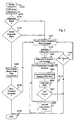
- Fig. 2 illustrates an exemplary method for entering a diagnostic link mode in accordance with this invention.
- control begins in step S100 and continues to step S110.
- step S110 the initialization sequence is commenced.
- step S120 if an initialization failure is detected, control continues to step S170. Otherwise, control jumps to step S130.
- step S 130 a determination is made whether the diagnostic link mode has been selected. If the diagnostic link mode has been selected, control continues to step S 170, otherwise, control jumps to step S140.
- step S170 the initiate diagnostic link mode message is transmitted from, for example, the remote terminal to the central office.
- step S180 a determination is made whether the initiate diagnostic mode message has been received by the CO. If the initiate diagnostic mode message has been received by the CO, control jumps to step S200. Otherwise, control continues to step S190.
- step S190 a determination is made whether to re-transmit the initiate diagnostic mode message, for example, based on whether a predetermined number of iterations have already been completed. If the initiate diagnostic mode message is to be re-transmitted, control continues back to step S 170. Otherwise, control jumps to step S160.
- step S200 the diagnostic link message is determined, for example, by assembling test and diagnostic information about one or more of the local loop, the modem itself, the telephone network at the remote terminal, or the like.
- steps S220-S240 arc completed.
- a diagnostic link message comprising a CRC is transmitted to, for example, the CO.
- step S230 the CRC is determined.
- step S240 a determination is made whether the CRC is correct. If the CRC is correct, the test and/or diagnostic information has been successfully communicated and control continues to step S160.
- step S210 if step S210 has completed the predetermined number of iterations, control continues to step S250.
- step S250 the transmission power is increased and control continues back to step S210.
- the diagnostic link message may be transmitted a predetermined number of times, with our without a change in the transmission power.
- step S140 the normal steady state data transmission is entered into between two moderns, such as the remote terminal and the cental office modems.
- step S150 a determination is made whether an error threshold during the normal steady state data transmission has been exceeded. If the error threshold has been exceeded, control continues to step S170. Otherwise, control jumps to step S160. In step S160, the control sequence ends.
- the diagnostic link mode system can be implemented either on a single program general purpose computer, a modem, such as a DSL modem, or a separate program general purpose computer having a communications device.
- the diagnostic link system can also be implemented on a special purpose computer, a programmed microprocessor or microcontroller and peripheral integrated circuit element, an ASIC or other integrated circuit, a digital signal processor, a hardwired electronic or logic circuit such as a discrete element circuit, a programmed logic device such as.a PLD. PLA, FPGA, PAL, or the like, and associated communications equipment.
- any device capable of implementing a finite state machine that is capable of implementing the flowchart illustrated in Fig. 2 can be used to implement a diagnostic link system according to this invention.
- the disclosed method may be readily implemented in software using object or object-oriented software development environments that provide portable source code that can be used on a variety of computer, workstation, or modem hardware platforms.
- the disclosed diagnostic link system may be implemented partially or fully in hardware using standard logic circuits or a VLSI design.
- the disclosed methods can be readily implemented as software executed on a programmed general purpose computer, a special purpose computer, a microprocessor, or the like.
- the methods and systems of this invention can be implemented as a program embedded on a modem, such a DSL modem, as a resource residing on a personal computer, as a routine embedded in a dedicated diagnostic link system, a central office, or the like.
- the diagnostic link system can also be implemented by physically incorporating the system and method into a software and/or hardware system, such as a hardware and software systems of a modem, a general purpose computer, an ADSL line testing device, or the like.
- the invention relates to the following aspects:
Applications Claiming Priority (5)
| Application Number | Priority Date | Filing Date | Title |
|---|---|---|---|
| US17486500P | 2000-01-07 | 2000-01-07 | |
| US22430800P | 2000-08-10 | 2000-08-10 | |
| PCT/US2001/000418 WO2001052516A2 (fr) | 2000-01-07 | 2001-01-08 | Systemes et procedes pour etablir un mode de transmission diagnostique et communiquer par l'intermediaire de celui-ci |
| EP01901808A EP1245093B1 (fr) | 2000-01-07 | 2001-01-08 | Systemes et procedes pour etablir un mode de transmission diagnostique et communiquer par l'intermediaire de celui-ci |
| EP20060022008 EP1755253B1 (fr) | 2000-01-07 | 2001-01-08 | Méthode diagnostique et émetteur-récepteur pour des modems à porteuses multiples |
Related Parent Applications (4)
| Application Number | Title | Priority Date | Filing Date |
|---|---|---|---|
| EP01901808A Division EP1245093B1 (fr) | 2000-01-07 | 2001-01-08 | Systemes et procedes pour etablir un mode de transmission diagnostique et communiquer par l'intermediaire de celui-ci |
| EP01901808.4 Division | 2001-01-08 | ||
| EP20060022008 Division EP1755253B1 (fr) | 2000-01-07 | 2001-01-08 | Méthode diagnostique et émetteur-récepteur pour des modems à porteuses multiples |
| EP06022008.4 Division | 2006-10-20 |
Publications (3)
| Publication Number | Publication Date |
|---|---|
| EP2276182A2 true EP2276182A2 (fr) | 2011-01-19 |
| EP2276182A3 EP2276182A3 (fr) | 2014-03-26 |
| EP2276182B1 EP2276182B1 (fr) | 2020-02-26 |
Family
ID=26870616
Family Applications (7)
| Application Number | Title | Priority Date | Filing Date |
|---|---|---|---|
| EP20100011983 Withdrawn EP2293459A3 (fr) | 2000-01-07 | 2001-01-08 | Systèmes et procédés permettant de caractériser des lignes de transmission dans un environnement DSL à ondes porteuses multiples |
| EP10011985.8A Expired - Lifetime EP2276182B1 (fr) | 2000-01-07 | 2001-01-08 | Systemes et procedes permettant de caracteriser des lignes de transmission dans un environnement dsl a ondes porteuses multiples |
| EP01901808A Expired - Lifetime EP1245093B1 (fr) | 2000-01-07 | 2001-01-08 | Systemes et procedes pour etablir un mode de transmission diagnostique et communiquer par l'intermediaire de celui-ci |
| EP18159847.5A Withdrawn EP3349386A1 (fr) | 2000-01-07 | 2001-01-08 | Systèmes de transmission dans un environnement dsl a ondes porteuses multiples |
| EP20060022008 Expired - Lifetime EP1755253B1 (fr) | 2000-01-07 | 2001-01-08 | Méthode diagnostique et émetteur-récepteur pour des modems à porteuses multiples |
| EP10011984.1A Expired - Lifetime EP2317684B1 (fr) | 2000-01-07 | 2001-01-08 | Système et procédés permettant d'établir un mode de transmission de diagnostic et communication sur celui-ci |
| EP10011982.5A Expired - Lifetime EP2270996B1 (fr) | 2000-01-07 | 2001-01-08 | Systemes et procedes permettant de caracteriser des lignes de transmission dans un environnement dsl a ondes porteuses multiples |
Family Applications Before (1)
| Application Number | Title | Priority Date | Filing Date |
|---|---|---|---|
| EP20100011983 Withdrawn EP2293459A3 (fr) | 2000-01-07 | 2001-01-08 | Systèmes et procédés permettant de caractériser des lignes de transmission dans un environnement DSL à ondes porteuses multiples |
Family Applications After (5)
| Application Number | Title | Priority Date | Filing Date |
|---|---|---|---|
| EP01901808A Expired - Lifetime EP1245093B1 (fr) | 2000-01-07 | 2001-01-08 | Systemes et procedes pour etablir un mode de transmission diagnostique et communiquer par l'intermediaire de celui-ci |
| EP18159847.5A Withdrawn EP3349386A1 (fr) | 2000-01-07 | 2001-01-08 | Systèmes de transmission dans un environnement dsl a ondes porteuses multiples |
| EP20060022008 Expired - Lifetime EP1755253B1 (fr) | 2000-01-07 | 2001-01-08 | Méthode diagnostique et émetteur-récepteur pour des modems à porteuses multiples |
| EP10011984.1A Expired - Lifetime EP2317684B1 (fr) | 2000-01-07 | 2001-01-08 | Système et procédés permettant d'établir un mode de transmission de diagnostic et communication sur celui-ci |
| EP10011982.5A Expired - Lifetime EP2270996B1 (fr) | 2000-01-07 | 2001-01-08 | Systemes et procedes permettant de caracteriser des lignes de transmission dans un environnement dsl a ondes porteuses multiples |
Country Status (13)
| Country | Link |
|---|---|
| US (17) | US6658052B2 (fr) |
| EP (7) | EP2293459A3 (fr) |
| JP (3) | JP2003520504A (fr) |
| KR (1) | KR100690111B1 (fr) |
| AT (2) | ATE343879T1 (fr) |
| AU (4) | AU776559B2 (fr) |
| CA (3) | CA2948960C (fr) |
| DE (1) | DE60124069T2 (fr) |
| DK (1) | DK1245093T3 (fr) |
| ES (1) | ES2272438T3 (fr) |
| HK (1) | HK1254420A1 (fr) |
| PT (1) | PT1245093E (fr) |
| WO (1) | WO2001052516A2 (fr) |
Families Citing this family (63)
| Publication number | Priority date | Publication date | Assignee | Title |
|---|---|---|---|---|
| EP2267914A3 (fr) | 2000-01-07 | 2012-09-26 | Aware, Inc. | Systèmes et procédés pour déterminer la longueur d'une boucle et d'un branchement en dérivation d'une ligne de transmission |
| EP2293459A3 (fr) | 2000-01-07 | 2014-04-16 | TQ Delta, LLC | Systèmes et procédés permettant de caractériser des lignes de transmission dans un environnement DSL à ondes porteuses multiples |
| EP1245085B1 (fr) | 2000-01-07 | 2006-07-05 | Aware, Inc. | Systemes et procedes pour determiner la longueur d'une boucle et d'un branchement en derivation d'une ligne de transmission |
| WO2001056200A1 (fr) * | 2000-01-26 | 2001-08-02 | Vyyo, Ltd. | Systeme de communication unidirectionnel pour l'entretien et la commande a distance dans un systeme d'acces sans fil a large bande |
| CA2689952A1 (fr) | 2000-04-18 | 2001-10-25 | Aware, Inc. | Systemes et procedes destines a un systeme de modulation a porteuses multiples presentant une marge variable |
| FR2812947B1 (fr) * | 2000-08-11 | 2002-11-08 | Dassault Automatismes | Procede et dispositif de mesure de l'attenuation d'une ligne |
| US7042837B1 (en) * | 2000-10-25 | 2006-05-09 | Sun Microsystems, Inc. | Automatic link failover in data networks |
| US7782933B2 (en) * | 2001-05-08 | 2010-08-24 | Alistair Malcolm Macdonald | Digital subscriber line diagnostic system |
| CA2354298A1 (fr) | 2001-07-30 | 2003-01-30 | Catena Networks Canada Inc. | Mode de diagnostic en boucle g.gen: g.dmt.bis: g.lite.bis: de la procedure d'initialisation |
| JP2003087348A (ja) * | 2001-09-14 | 2003-03-20 | Matsushita Graphic Communication Systems Inc | 通信制御方法及び通信制御装置並びにadsl通信装置 |
| WO2003040736A1 (fr) * | 2001-11-07 | 2003-05-15 | Aware, Inc. | Modelisation et calibrage d'un systeme de reflectometrie a dimension temporelle a trois points d'acces |
| US7352722B2 (en) * | 2002-05-13 | 2008-04-01 | Qualcomm Incorporated | Mitigation of link imbalance in a wireless communication system |
| IL152824A (en) | 2002-11-13 | 2012-05-31 | Mosaid Technologies Inc | A socket that can be connected to and the network that uses it |
| FR2849302B1 (fr) * | 2002-12-18 | 2007-04-20 | Acterna Ipms | Procede de controle non intrusif d'une ligne de transmission du type xdsl |
| KR20060069463A (ko) | 2003-08-21 | 2006-06-21 | 어웨어, 인크. | 비선형 장치 검출 |
| US7302379B2 (en) * | 2003-12-07 | 2007-11-27 | Adaptive Spectrum And Signal Alignment, Inc. | DSL system estimation and parameter recommendation |
| WO2007008835A2 (fr) * | 2005-07-10 | 2007-01-18 | Adaptive Spectrum And Signal Alignment, Inc. | Estimation de systeme dsl |
| US7809116B2 (en) * | 2003-12-07 | 2010-10-05 | Adaptive Spectrum And Signal Alignment, Inc. | DSL system estimation including known DSL line scanning and bad splice detection capability |
| US7272209B2 (en) * | 2004-01-20 | 2007-09-18 | Sbc Knowledge Ventures, L.P. | Automated DSL performance adjustment |
| US7356475B2 (en) * | 2004-01-05 | 2008-04-08 | Sbc Knowledge Ventures, L.P. | System and method for providing access to an interactive service offering |
| US7362713B2 (en) | 2004-01-20 | 2008-04-22 | Sbc Knowledge Ventures, Lp. | System and method for accessing digital subscriber line data |
| US7126914B2 (en) * | 2004-01-28 | 2006-10-24 | Sbc Knowledge Ventures, Lp | Digital subscriber line user capacity estimation |
| US7123584B2 (en) * | 2004-01-28 | 2006-10-17 | Sbc Knowledge Ventures, L.P. | Digital subscriber line user capacity estimation |
| US20060285496A1 (en) * | 2004-01-28 | 2006-12-21 | Sbc Knowledge Ventures, L.P. | Digital subscriber line user capacity estimation |
| US7342920B2 (en) * | 2004-01-28 | 2008-03-11 | Sbc Knowledge Ventures, L.P. | Voice over internet protocol (VoIP) telephone apparatus and communications systems for carrying VoIP traffic |
| US7876775B2 (en) * | 2004-02-12 | 2011-01-25 | At&T Intellectual Property I, L.P. | Connection management for data networks |
| KR100825772B1 (ko) * | 2004-02-13 | 2008-04-28 | 삼성전자주식회사 | Adsl 시스템의 통신 링크 셋-업 방법 |
| DE102004012892B4 (de) * | 2004-03-16 | 2010-10-07 | Nokia Siemens Networks Gmbh & Co.Kg | Paketorientiertes Datenübertragungssystem mit für die jeweilige Datenübertragungsverbindung wählbaren Betriebsmodus |
| US7570599B2 (en) * | 2004-04-21 | 2009-08-04 | At&T Intellectual Property I, Llp. | Adaptively applying a target noise margin to a digital subscriber line (DSL) loop for DSL data rate establishment |
| US7388906B2 (en) * | 2004-05-03 | 2008-06-17 | Sbc Knowledge Ventures, L.P. | Method for detecting bridged taps on telephony cable |
| US7518991B2 (en) | 2004-10-27 | 2009-04-14 | At&T Intellectual Property I, L.P. | System and method for troubleshooting broadband connections |
| DE602004031745D1 (de) * | 2004-12-24 | 2011-04-21 | Alcatel Lucent | Testverfahren und Einrichtung zur Identifizierung von internen Leitungsproblemen |
| US7558213B2 (en) * | 2005-06-15 | 2009-07-07 | AT&T Intellectual Property I, LLP | Methods and apparatus to determine digital subscriber line configuration parameters |
| US7873981B2 (en) * | 2005-12-28 | 2011-01-18 | At&T Intellectual Property I, L.P. | Methods, systems and computer program products for providing internet protocol television set up |
| US7823183B2 (en) | 2005-12-28 | 2010-10-26 | At&T Intellectual Property I, L.P. | Methods, systems and computer program products for providing internet protocol television communication services |
| US20070162932A1 (en) * | 2005-12-28 | 2007-07-12 | Mickle Jacklyn A | Methods, systems and computer program products for providing internet protocol television troubleshooting |
| US20070162929A1 (en) * | 2005-12-28 | 2007-07-12 | Mickle Jacklyn A | Methods, systems and computer program products for providing internet protocol television contextual support |
| US8254277B2 (en) | 2005-12-28 | 2012-08-28 | At&T Intellectual Property I, L.P. | Methods, systems and computer program products for providing internet protocol television diagnostics |
| US8040835B2 (en) * | 2006-02-17 | 2011-10-18 | Cisco Technology, Inc. | Troubleshooting link and protocol in a wireless network |
| CN1909394A (zh) * | 2006-08-11 | 2007-02-07 | 华为技术有限公司 | 诊断数字用户线收发器互通性问题的系统和方法 |
| US20090016720A1 (en) * | 2007-07-11 | 2009-01-15 | Inventec Multimedia & Telecom (Tianjin) Co., Ltd. | Problem detection device at ONU end in PON system and method thereof |
| US7983179B2 (en) * | 2007-07-27 | 2011-07-19 | At&T Intellectual Property I, L.P. | Network monitoring by customer premises equipment |
| TW200934154A (en) * | 2007-12-28 | 2009-08-01 | Panasonic Corp | Communication device and communication system |
| EP2250801B1 (fr) | 2008-01-29 | 2017-03-15 | Broadcom Corporation | Procede et systeme de detection de dispositifs non lineaires |
| US8170088B2 (en) * | 2008-11-19 | 2012-05-01 | Harris Corporation | Methods for determining a reference signal at any location along a transmission media |
| US20100123618A1 (en) * | 2008-11-19 | 2010-05-20 | Harris Corporation | Closed loop phase control between distant points |
| US20100124263A1 (en) * | 2008-11-19 | 2010-05-20 | Harris Corporation | Systems for determining a reference signal at any location along a transmission media |
| WO2010060086A1 (fr) * | 2008-11-24 | 2010-05-27 | Aware, Inc. | Détection de défaillances concernant des liaisons de communication |
| US8112669B2 (en) * | 2009-08-31 | 2012-02-07 | Comsonics, Inc. | Wireless diagnostic system |
| US8665897B2 (en) * | 2009-10-26 | 2014-03-04 | Adc Dsl Systems, Inc. | Systems and methods for high-speed digital subscriber line software download |
| US9258411B2 (en) * | 2009-11-04 | 2016-02-09 | Broadcom Corporation | Forensic diagnostic capability including G.inp |
| US9130655B2 (en) * | 2009-11-30 | 2015-09-08 | Broadcom Corporation | Methods and systems for detecting metallic faults affecting communications links |
| JP2011158971A (ja) | 2010-01-29 | 2011-08-18 | Seiko Epson Corp | 情報処理装置、通信装置、無線診断方法、および、プログラム |
| JP5617260B2 (ja) | 2010-01-29 | 2014-11-05 | セイコーエプソン株式会社 | 情報処理装置 |
| EP2571237A1 (fr) * | 2011-09-13 | 2013-03-20 | Technicolor Delivery Technologies Belgium | Procédé pour démarrer un mode de sauvegarde pour un système de transmission XDSL et passerelle résidentielle utilisant le procédé |
| US9621445B2 (en) | 2015-01-25 | 2017-04-11 | Valens Semiconductor Ltd. | Utilizing known data for status signaling |
| US10256920B2 (en) | 2015-01-25 | 2019-04-09 | Valens Semiconductor Ltd. | Mode-conversion digital canceller for high bandwidth differential signaling |
| US10171182B2 (en) | 2015-01-25 | 2019-01-01 | Valens Semiconductor Ltd. | Sending known data to support fast convergence |
| US9685991B2 (en) | 2015-01-25 | 2017-06-20 | Valens Semiconductor Ltd. | Reducing transmission rate to support fast convergence |
| EP3293931A1 (fr) | 2015-01-25 | 2018-03-14 | Valens Semiconductor Ltd. | Émetteur-récepteur et procédé pour récupérer vite une dégradation de la qualité |
| US10826754B1 (en) * | 2019-04-15 | 2020-11-03 | Microsoft Technology Licensing, Llc | Detecting malfunction of mobile broadband modems based on response patterns |
| US10892796B1 (en) | 2020-03-20 | 2021-01-12 | Rockwell Collins, Inc. | UWB spread spectrum power spatial combining antenna array |
| US11874394B2 (en) | 2020-04-02 | 2024-01-16 | Rockwell Collins, Inc. | System and method for improving signal qualification |
Family Cites Families (164)
| Publication number | Priority date | Publication date | Assignee | Title |
|---|---|---|---|---|
| US3836726A (en) * | 1971-10-25 | 1974-09-17 | Martin Marietta Corp | Data transmission method and apparatus |
| US4385384A (en) * | 1977-06-06 | 1983-05-24 | Racal Data Communications Inc. | Modem diagnostic and control system |
| FR2466144B1 (fr) * | 1979-09-18 | 1986-11-07 | Lignes Telegraph Telephon | Procede de test d'une ligne de transmission de donnees numeriques entre deux modems et dispositif mettant en oeuvre ce procede |
| US4438511A (en) | 1980-11-10 | 1984-03-20 | Telebit Corporation | Packetized ensemble modem |
| JPS58182356A (ja) * | 1982-04-20 | 1983-10-25 | Kokusai Denshin Denwa Co Ltd <Kdd> | ビツト誤り率測定方式 |
| JPS60206346A (ja) | 1984-03-30 | 1985-10-17 | Fujitsu Ltd | 変復調装置設定方式 |
| US4833706A (en) | 1985-05-20 | 1989-05-23 | Telebit Corporation | Ensemble modem structure for imperfect transmission media |
| US4679227A (en) | 1985-05-20 | 1987-07-07 | Telebit Corporation | Ensemble modem structure for imperfect transmission media |
| JPH063956Y2 (ja) | 1986-03-14 | 1994-02-02 | 松下電工株式会社 | 電動ガレ−ジ扉 |
| US5214501A (en) | 1988-10-03 | 1993-05-25 | North American Philips Corporation | Method and apparatus for the transmission and reception of a multicarrier high definition television signal |
| US4979174A (en) | 1988-12-29 | 1990-12-18 | At&T Bell Laboratories | Error correction and detection apparatus and method |
| US5128619A (en) | 1989-04-03 | 1992-07-07 | Bjork Roger A | System and method of determining cable characteristics |
| US5023873A (en) * | 1989-06-15 | 1991-06-11 | International Business Machines Corporation | Method and apparatus for communication link management |
| GB9010637D0 (en) | 1990-05-11 | 1990-07-04 | Secr Defence | A high frequency multichannel diversity differential phase shift(dpsk)communications system |
| US5388252A (en) * | 1990-09-07 | 1995-02-07 | Eastman Kodak Company | System for transparent monitoring of processors in a network with display of screen images at a remote station for diagnosis by technical support personnel |
| US5239671A (en) | 1990-11-13 | 1993-08-24 | Pagemart, Inc. | Simulcast satellite paging system with provision for signal interruption |
| US5313197A (en) * | 1991-09-27 | 1994-05-17 | Motorola, Inc. | Self-diagnostic paging system |
| US5612960A (en) * | 1991-12-20 | 1997-03-18 | Ncr Corporation | Radio LAN station with improved point-to-point link diagnostic capability and method of operation thereof |
| US5557616A (en) * | 1992-04-02 | 1996-09-17 | Applied Digital Access, Inc. | Frame synchronization in a performance monitoring and test system |
| US5361293A (en) * | 1992-04-16 | 1994-11-01 | Alcatel Network Systems, Inc. | Line/drop testing from a craft terminal using test unit |
| JPH063956A (ja) | 1992-06-17 | 1994-01-14 | Seiko Epson Corp | 記録材料の残量検出装置 |
| US5287384A (en) | 1992-10-15 | 1994-02-15 | Lxe Inc. | Frequency hopping spread spectrum data communications system |
| US5995539A (en) | 1993-03-17 | 1999-11-30 | Miller; William J. | Method and apparatus for signal transmission and reception |
| US5351016A (en) | 1993-05-28 | 1994-09-27 | Ericsson Ge Mobile Communications Inc. | Adaptively self-correcting modulation system and method |
| US5438329A (en) | 1993-06-04 | 1995-08-01 | M & Fc Holding Company, Inc. | Duplex bi-directional multi-mode remote instrument reading and telemetry system |
| US5596604A (en) | 1993-08-17 | 1997-01-21 | Amati Communications Corporation | Multicarrier modulation transmission system with variable delay |
| US5420640A (en) | 1993-12-03 | 1995-05-30 | Scientific-Atlanta, Inc. | Memory efficient method and apparatus for sync detection |
| FR2723282B1 (fr) | 1994-07-29 | 1996-09-13 | Alcatel Telspace | Procede d'entrelacement et de desentrelacement de trames sdh et systeme correspondant |
| US5608643A (en) * | 1994-09-01 | 1997-03-04 | General Programming Holdings, Inc. | System for managing multiple dispensing units and method of operation |
| US5764693A (en) | 1994-11-14 | 1998-06-09 | Research In Motion Limited | Wireless radio modem with minimal inter-device RF interference |
| US5549512A (en) | 1994-11-30 | 1996-08-27 | Lucent Technologies Inc. | Minienvironment for hazardous process tools |
| US6421323B1 (en) | 1994-12-23 | 2002-07-16 | Applied Digital Access, Inc. | Method and apparatus for analyzing events in a telecommunications system |
| US5751338A (en) | 1994-12-30 | 1998-05-12 | Visionary Corporate Technologies | Methods and systems for multimedia communications via public telephone networks |
| US5574747A (en) | 1995-01-04 | 1996-11-12 | Interdigital Technology Corporation | Spread spectrum adaptive power control system and method |
| US5521906A (en) | 1995-01-26 | 1996-05-28 | Motorola Inc. | Method and apparatus for updating carrier channel allocations |
| US5533008A (en) | 1995-01-26 | 1996-07-02 | Motorola, Inc. | Method and apparatus for providing a communication system infrastructure |
| CN1193433A (zh) | 1995-02-06 | 1998-09-16 | Adc长途电讯有限公司 | 使用奇偶校验位的通信信道监控方法 |
| US5546411A (en) | 1995-02-28 | 1996-08-13 | Motorola, Inc. | Method and apparatus for adaptively selecting a communication strategy in a selective call radio communication system |
| KR0155818B1 (ko) | 1995-04-29 | 1998-11-16 | 김광호 | 다중 반송파 전송시스템에서 적응형 전력 분배 방법 및 장치 |
| US5635864A (en) | 1995-06-07 | 1997-06-03 | Discovision Associates | Comparator circuit |
| US5812786A (en) | 1995-06-21 | 1998-09-22 | Bell Atlantic Network Services, Inc. | Variable rate and variable mode transmission system |
| US5726978A (en) | 1995-06-22 | 1998-03-10 | Telefonaktiebolaget L M Ericsson Publ. | Adaptive channel allocation in a frequency division multiplexed system |
| AT406533B (de) * | 1995-06-26 | 2000-06-26 | Ericsson Austria Ag | Verfahren zur bidirektionalen datenübertragung über eine zweidrahtleitung |
| KR100331437B1 (ko) * | 1995-06-30 | 2002-08-08 | 삼성전자 주식회사 | 디.엠.티.시스템에서적응형비트교환방법및장치 |
| DE69535033T2 (de) | 1995-07-11 | 2007-03-08 | Alcatel | Zuweisung von Kapazität bei OFDM |
| US5793759A (en) | 1995-08-25 | 1998-08-11 | Terayon Corporation | Apparatus and method for digital data transmission over video cable using orthogonal cyclic codes |
| US5644634A (en) | 1995-11-29 | 1997-07-01 | Advanced Micro Devices | System and method for dual tone multifrequency detection using variable frame widths |
| US5862451A (en) | 1996-01-22 | 1999-01-19 | Motorola, Inc. | Channel quality management in a cable telephony system |
| EP0888672B1 (fr) * | 1996-03-29 | 2005-07-27 | Motorola, Inc. | Appareil et procede de gestion du spectre dans un systeme de telecommunications par acces multiple |
| US5764649A (en) | 1996-03-29 | 1998-06-09 | Amati Communications Corporation | Efficient address generation for convolutional interleaving using a minimal amount of memory |
| US6002722A (en) | 1996-05-09 | 1999-12-14 | Texas Instruments Incorporated | Multimode digital modem |
| US5910970A (en) | 1996-05-09 | 1999-06-08 | Texas Instruments Incorporated | MDSL host interface requirement specification |
| US6072779A (en) | 1997-06-12 | 2000-06-06 | Aware, Inc. | Adaptive allocation for variable bandwidth multicarrier communication |
| US5764896A (en) | 1996-06-28 | 1998-06-09 | Compaq Computer Corporation | Method and system for reducing transfer latency when transferring data from a network to a computer system |
| EP0922343B1 (fr) | 1996-09-02 | 2002-11-13 | STMicroelectronics N.V. | Perfectionnements relatifs aux systemes de transmission a porteuses multiples |
| WO1998010552A2 (fr) | 1996-09-02 | 1998-03-12 | Telia Ab | Perfectionnements relatifs a des systemes de transmission a porteuses multiples |
| WO1998010549A2 (fr) | 1996-09-02 | 1998-03-12 | Telia Ab | Perfectionnements relatifs a des systemes de transmission a porteuses multiples |
| WO1998010545A1 (fr) | 1996-09-02 | 1998-03-12 | Telia Ab | Ameliorations relatives aux systemes de transmission a porteuses multiples |
| ATE228286T1 (de) | 1996-09-02 | 2002-12-15 | St Microelectronics Nv | Verbesserungen bei, oder in bezug auf mehrträgerübertragungssysteme |
| US6493395B1 (en) | 1996-09-02 | 2002-12-10 | Stmicroelectronics N.V. | Multi-carrier transmission systems |
| JP4447056B2 (ja) | 1996-09-02 | 2010-04-07 | エステー マイクロエレクトロニクス ナームローゼ ベンノートシャップ | 多重搬送波伝送システムにおける、あるいはそれに関する改良 |
| JP2001505373A (ja) | 1996-09-02 | 2001-04-17 | テリア アクティエ ボラーグ | 多重搬送波伝送システムにおける、あるいはそれに関する改良 |
| DE19638654A1 (de) | 1996-09-20 | 1998-03-26 | Siemens Ag | Verfahren zur digitalen Nachrichtenübertragung |
| US5745275A (en) | 1996-10-15 | 1998-04-28 | Lucent Technologies Inc. | Multi-channel stabilization of a multi-channel transmitter through correlation feedback |
| GB2319703A (en) | 1996-11-02 | 1998-05-27 | Plessey Telecomm | AFC in a DMT receiver |
| US5903612A (en) | 1996-11-08 | 1999-05-11 | Alcatel Alsthom Compagnie Generale D'electricite | Method to synchronize data and a transmitter and a receiver realizing said method |
| DE19647833B4 (de) * | 1996-11-19 | 2005-07-07 | Deutsches Zentrum für Luft- und Raumfahrt e.V. | Verfahren zur gleichzeitigen Funkübertragung digitaler Daten zwischen mehreren Teilnehmerstationen und einer Basisstation |
| KR19980043696A (ko) | 1996-12-04 | 1998-09-05 | 김광호 | 다중 반송파 시스템에서 효율적인 신호대 잡음비의 계산방법 |
| US6253060B1 (en) | 1996-12-20 | 2001-06-26 | Airnet Communications Corporation | Method and apparatus employing wireless remote loopback capability for a wireless system repeater to provide end-to-end testing without a wireline connection |
| US5838268A (en) | 1997-03-14 | 1998-11-17 | Orckit Communications Ltd. | Apparatus and methods for modulation and demodulation of data |
| US6041057A (en) | 1997-03-24 | 2000-03-21 | Xylan Corporation | Self-configuring ATM network |
| DE19882318T1 (de) | 1997-04-14 | 2000-04-13 | Northern Telecom Ltd | Verfahren und System zur Vermeidung einer Kommunikationsstörung in CDMA-Systemen |
| US5864602A (en) | 1997-04-28 | 1999-01-26 | Nynex Science & Technologies, Inc. | Qualifying telephone line for digital transmission service |
| US6064692A (en) | 1997-06-20 | 2000-05-16 | Amati Communications Corporation | Protocol for transceiver initialization |
| US6065060A (en) * | 1997-06-30 | 2000-05-16 | Integrated Telecom Express | Modular multiplicative data rate modem and method of operation |
| US6073179A (en) * | 1997-06-30 | 2000-06-06 | Integrated Telecom Express | Program for controlling DMT based modem using sub-channel selection to achieve scaleable data rate based on available signal processing resources |
| US6128335A (en) | 1997-06-30 | 2000-10-03 | Integrated Telecom Express | Software rate adaptable modem with forward compatible and expandable functionality and method of operation |
| US6252900B1 (en) | 1997-06-30 | 2001-06-26 | Integrated Telecom Express, Inc. | Forward compatible and expandable high speed communications system and method of operation |
| US6314102B1 (en) | 1997-07-10 | 2001-11-06 | Alcatel | Telecommunications system for providing both narrowband and broadband services to subscribers |
| US6011970A (en) * | 1997-07-23 | 2000-01-04 | Nortel Networks Corporation | Method and system for assuring near uniform capacity and quality of channels in cells of wireless communications systems having cellular architectures |
| US5964891A (en) * | 1997-08-27 | 1999-10-12 | Hewlett-Packard Company | Diagnostic system for a distributed data access networked system |
| US6366644B1 (en) | 1997-09-15 | 2002-04-02 | Cisco Technology, Inc. | Loop integrity test device and method for digital subscriber line (XDSL) communication |
| US6219378B1 (en) * | 1997-09-17 | 2001-04-17 | Texas Instruments Incorporated | Digital subscriber line modem initialization |
| US6005893A (en) | 1997-09-23 | 1999-12-21 | Telefonaktiebolaget Lm Ericsson | Reduced complexity bit allocation to subchannels in a multi-carrier, high speed data transmission system |
| US6130882A (en) | 1997-09-25 | 2000-10-10 | Motorola, Inc. | Method and apparatus for configuring a communication system |
| US6101216A (en) | 1997-10-03 | 2000-08-08 | Rockwell International Corporation | Splitterless digital subscriber line communication system |
| US5917340A (en) | 1997-10-08 | 1999-06-29 | Pericom Semiconductor Corp. | Twisted-pair driver with staggered differential drivers and glitch free binary to multi level transmit encoder |
| KR100640320B1 (ko) * | 1997-10-10 | 2006-10-31 | 어웨어, 인크. | 스플리터없는 멀티캐리어 모뎀 |
| EP0966808A2 (fr) * | 1997-11-14 | 1999-12-29 | Tektronix, Inc. | Methode d'exploitation d'un reseau de distribution de donnees numeriques |
| US6459678B1 (en) | 1997-12-05 | 2002-10-01 | Globespan Semiconductor, Inc. | System and method for providing near optimal bit loading in a discrete multi-tone modulation system |
| US6175934B1 (en) * | 1997-12-15 | 2001-01-16 | General Electric Company | Method and apparatus for enhanced service quality through remote diagnostics |
| US6075821A (en) | 1997-12-16 | 2000-06-13 | Integrated Telecom Express | Method of configuring and dynamically adapting data and energy parameters in a multi-channel communications system |
| US6308278B1 (en) | 1997-12-29 | 2001-10-23 | Intel Corporation | Supplying standby voltage to memory and wakeup circuitry to wake a computer from a low power mode |
| US6144696A (en) | 1997-12-31 | 2000-11-07 | At&T Corp. | Spread spectrum bit allocation algorithm |
| JP3027813B2 (ja) * | 1998-01-09 | 2000-04-04 | 松下電送システム株式会社 | 通信装置及び通信方法 |
| EP0930752A3 (fr) * | 1998-01-14 | 1999-10-20 | Motorola, Inc. | Procédé d'allocation de données et de pouvoir dans un système de communcication multiporteur |
| US6275522B1 (en) | 1998-01-14 | 2001-08-14 | Motorola, Inc. | Method for allocating data and power in a discrete, multi-tone communication system |
| US6445730B1 (en) | 1998-01-26 | 2002-09-03 | Aware, Inc. | Multicarrier transmission system with low power sleep mode and rapid-on capability |
| US6363109B1 (en) | 1998-02-03 | 2002-03-26 | Texas Instruments Incorporated | Methods and device for estimating and correcting clipping in a discrete multi-tone communications system |
| US6686879B2 (en) | 1998-02-12 | 2004-02-03 | Genghiscomm, Llc | Method and apparatus for transmitting and receiving signals having a carrier interferometry architecture |
| US6781513B1 (en) * | 1998-03-03 | 2004-08-24 | General Electric Company | Telemetry of diagnostic messages from a mobile asset to a remote station |
| US6434119B1 (en) | 1998-03-19 | 2002-08-13 | Texas Instruments Incorporated | Initializing communications in systems using multi-carrier modulation |
| US6226322B1 (en) | 1998-03-30 | 2001-05-01 | Texas Instruments Incorporated | Analog receive equalizer for digital-subscriber-line communications system |
| US6154489A (en) | 1998-03-30 | 2000-11-28 | Motorola, Inc. | Adaptive-rate coded digital image transmission |
| US6052411A (en) | 1998-04-06 | 2000-04-18 | 3Com Corporation | Idle mode for digital subscriber line |
| US6404774B1 (en) * | 1998-04-08 | 2002-06-11 | Siemens Information And Communication Networks, Inc. | Method using low spectrum selectively for providing both ADSL and POTS service |
| US6243369B1 (en) | 1998-05-06 | 2001-06-05 | Terayon Communication Systems, Inc. | Apparatus and method for synchronizing an SCDMA upstream or any other type upstream to an MCNS downstream or any other type downstream with a different clock rate than the upstream |
| US6292539B1 (en) | 1998-05-29 | 2001-09-18 | Verizon Laboratories Inc. | Method and apparatus for digital subscriber loop qualification |
| JP3419342B2 (ja) * | 1998-06-05 | 2003-06-23 | 株式会社村田製作所 | 測定器 |
| EP1090463A1 (fr) * | 1998-06-23 | 2001-04-11 | PC Tel, Inc. | Poignee de main a spectre etale destinee aux systemes de telecommunications a ligne d'abonne numerique |
| US6532215B1 (en) * | 1998-08-07 | 2003-03-11 | Cisco Technology, Inc. | Device and method for network communications and diagnostics |
| US6697626B1 (en) | 1998-11-30 | 2004-02-24 | Skyworks Solutions, Inc. | Using channel loading statistics to determine whether to search for a new channel in a wireless communication system |
| JP2002532953A (ja) | 1998-12-08 | 2002-10-02 | グローブスパン ヴィラタ、インコーポレイテッド | 時間デュープレックス雑音環境において動作しているadslシステム用の代替構成 |
| US6891803B1 (en) | 1998-12-18 | 2005-05-10 | Sunrise Telecom, Inc. | Telecommunications transmission test set |
| US6646994B1 (en) | 1998-12-28 | 2003-11-11 | Globespanvirata, Inc. | System and method for controlling distortion in the POTS band in a dual POTS and discrete multi-tone communication system |
| US6151328A (en) | 1998-12-31 | 2000-11-21 | Lg Information & Communications Ltd. | Apparatus and method for controlling power in code division multiple access system |
| WO2000041395A1 (fr) | 1999-01-06 | 2000-07-13 | Sarnoff Corporation | Multiplexage statistique sur la base du temps d'attente |
| US6385773B1 (en) * | 1999-01-07 | 2002-05-07 | Cisco Techology, Inc. | Method and apparatus for upstream frequency channel transition |
| US6578162B1 (en) | 1999-01-20 | 2003-06-10 | Skyworks Solutions, Inc. | Error recovery method and apparatus for ADPCM encoded speech |
| US6424674B1 (en) | 1999-01-22 | 2002-07-23 | Legerity, Inc. | Multi-tone transciever for multiple users |
| US6516027B1 (en) * | 1999-02-18 | 2003-02-04 | Nec Usa, Inc. | Method and apparatus for discrete multitone communication bit allocation |
| US6829307B1 (en) | 1999-02-24 | 2004-12-07 | The Board Of Trustees Of Leland Stanford Junior University | Express bit swapping in a multicarrier transmission system |
| US6473418B1 (en) | 1999-03-11 | 2002-10-29 | Flarion Technologies, Inc. | Orthogonal frequency division multiplexing based spread spectrum multiple access |
| US6754290B1 (en) | 1999-03-31 | 2004-06-22 | Qualcomm Incorporated | Highly parallel map decoder |
| EP1699143B1 (fr) | 1999-03-31 | 2008-01-23 | Alcatel Lucent | Méthode et agencement pour l'estimation de caractéristiques d'un canal de transmission |
| US6590893B1 (en) | 1999-04-07 | 2003-07-08 | Legerity, Inc. | Adaptive transmission system in a network |
| US6895081B1 (en) | 1999-04-20 | 2005-05-17 | Teradyne, Inc. | Predicting performance of telephone lines for data services |
| US6177801B1 (en) | 1999-04-21 | 2001-01-23 | Sunrise Telecom, Inc. | Detection of bridge tap using frequency domain analysis |
| US6512789B1 (en) * | 1999-04-30 | 2003-01-28 | Pctel, Inc. | Partial equalization for digital communication systems |
| KR20010074734A (ko) | 1999-05-21 | 2001-08-09 | 히노 다카시 | 핸드셰이킹 프로토콜을 위한 재송신 절차 및 장치 |
| WO2000072583A1 (fr) | 1999-05-21 | 2000-11-30 | General Instrument Corporation | Architecture logicielle pour terminal decodeur tv compatible avec de multiples environnements operationnels |
| DE69938906D1 (de) | 1999-05-21 | 2008-07-24 | Fujitsu Ltd | Digitales Teilnehmerleitungsverfahren, -gerät und -system unter Verwendung synchroner Verarbeitung |
| US6636505B1 (en) * | 1999-05-28 | 2003-10-21 | 3Com Corporation | Method for service provisioning a broadband modem |
| US6847702B1 (en) | 1999-05-28 | 2005-01-25 | Alcatel Usa Sourcing, L.P. | Systems and methods for enhanced reliability in a communication system |
| US6657949B1 (en) | 1999-07-06 | 2003-12-02 | Cisco Technology, Inc. | Efficient request access for OFDM systems |
| US6631120B1 (en) * | 1999-07-30 | 2003-10-07 | Cisco Technology, Inc. | System and method for determining a communication protocol of a communication device operating on digital subscriber lines |
| US6633545B1 (en) * | 1999-07-30 | 2003-10-14 | Cisco Technology, Inc. | System and method for determining the data rate capacity of digital subscriber lines |
| US6636603B1 (en) * | 1999-07-30 | 2003-10-21 | Cisco Technology, Inc. | System and method for determining the transmit power of a communication device operating on digital subscriber lines |
| WO2001011833A1 (fr) | 1999-08-06 | 2001-02-15 | Berkeley Concept Research Corporation | Reseau sans fil extremement rapide possedant une voie fiable sans fil a debit binaire limite |
| US6618745B2 (en) * | 1999-09-10 | 2003-09-09 | Fisher Rosemount Systems, Inc. | Linking device in a process control system that allows the formation of a control loop having function blocks in a controller and in field devices |
| US6553515B1 (en) | 1999-09-10 | 2003-04-22 | Comdial Corporation | System, method and computer program product for diagnostic supervision of internet connections |
| US6892339B1 (en) | 1999-09-20 | 2005-05-10 | Freescale Semiconductor, Inc. | Discrete multi-tone (DMT) system and method that communicates a data pump data stream between a general purpose CPU and a DSP via a buffering scheme |
| US6411678B1 (en) * | 1999-10-01 | 2002-06-25 | General Electric Company | Internet based remote diagnostic system |
| US6898185B1 (en) | 1999-10-20 | 2005-05-24 | Broadcom Corporation | Diagnostics of cable and link performance for a high-speed communication system |
| US6640239B1 (en) | 1999-11-10 | 2003-10-28 | Garuda Network Corporation | Apparatus and method for intelligent scalable switching network |
| US6996067B1 (en) * | 1999-12-07 | 2006-02-07 | Verizon Services Corp. | Apparatus for and method of providing and measuring data throughput to and from a packet data network |
| WO2001045340A1 (fr) | 1999-12-16 | 2001-06-21 | Aware, Inc. | Procede d'affectation binaire dans un systeme a porteuses multiples |
| US6748212B2 (en) | 1999-12-29 | 2004-06-08 | Airnet Communications Corporation | Method and apparatus for backhaul link diagnostic in a wireless repeater system |
| EP2293459A3 (fr) * | 2000-01-07 | 2014-04-16 | TQ Delta, LLC | Systèmes et procédés permettant de caractériser des lignes de transmission dans un environnement DSL à ondes porteuses multiples |
| US6788705B1 (en) | 2000-01-18 | 2004-09-07 | Lucent Technologies Inc. | Transmitting DSL startup parameters over a voice channel |
| US7032223B2 (en) | 2000-03-01 | 2006-04-18 | Realtek Semiconductor Corp. | Transport convergence sub-system with shared resources for multiport xDSL system |
| US6473467B1 (en) | 2000-03-22 | 2002-10-29 | Qualcomm Incorporated | Method and apparatus for measuring reporting channel state information in a high efficiency, high performance communications system |
| US6445773B1 (en) * | 2000-06-14 | 2002-09-03 | Consultronics Limited | DMT test method for determining ADSL capability of cables |
| ATE422739T1 (de) | 2000-08-03 | 2009-02-15 | Infineon Technologies Ag | Flexible tdma systemarchitektur |
| US7024592B1 (en) | 2000-08-07 | 2006-04-04 | Cigital | Method for reducing catastrophic failures in continuously operating software systems |
| US6690655B1 (en) * | 2000-10-19 | 2004-02-10 | Motorola, Inc. | Low-powered communication system and method of operation |
| US7203206B2 (en) | 2001-02-06 | 2007-04-10 | Tioga Technologies Inc. | Data partitioning for multi-link transmission |
| US6829330B2 (en) * | 2001-04-26 | 2004-12-07 | Aware, Inc. | Systems and methods for loop characterization from double-ended measurements |
| AUPR679201A0 (en) | 2001-08-03 | 2001-08-30 | Lucent Technologies Inc. | Path metric normalization of add-compare-select processing |
| US6725176B1 (en) * | 2001-08-03 | 2004-04-20 | Centilliune Communications, Inc. | Loop diagnostics for ADSL systems |
| US6904537B1 (en) | 2001-08-27 | 2005-06-07 | Network Elements, Inc. | Data transmission across asynchronous time domains using phase-shifted data packet |
| KR100724438B1 (ko) | 2001-12-26 | 2007-06-04 | 엘지전자 주식회사 | 기지국 모뎀의 메모리 제어장치 |
| US7027539B2 (en) | 2002-12-09 | 2006-04-11 | Broadcom Corporation | Pipeline architecture for multi-slot wireless link processing |
| US7623894B2 (en) | 2003-10-09 | 2009-11-24 | Freescale Semiconductor, Inc. | Cellular modem processing |
-
2001
- 2001-01-08 EP EP20100011983 patent/EP2293459A3/fr not_active Withdrawn
- 2001-01-08 US US09/755,173 patent/US6658052B2/en not_active Expired - Lifetime
- 2001-01-08 CA CA2948960A patent/CA2948960C/fr not_active Expired - Lifetime
- 2001-01-08 AT AT01901808T patent/ATE343879T1/de active
- 2001-01-08 KR KR1020027008794A patent/KR100690111B1/ko not_active IP Right Cessation
- 2001-01-08 WO PCT/US2001/000418 patent/WO2001052516A2/fr active IP Right Grant
- 2001-01-08 EP EP10011985.8A patent/EP2276182B1/fr not_active Expired - Lifetime
- 2001-01-08 EP EP01901808A patent/EP1245093B1/fr not_active Expired - Lifetime
- 2001-01-08 EP EP18159847.5A patent/EP3349386A1/fr not_active Withdrawn
- 2001-01-08 JP JP2001552611A patent/JP2003520504A/ja active Pending
- 2001-01-08 EP EP20060022008 patent/EP1755253B1/fr not_active Expired - Lifetime
- 2001-01-08 AT AT06022008T patent/ATE516635T1/de not_active IP Right Cessation
- 2001-01-08 DK DK01901808T patent/DK1245093T3/da active
- 2001-01-08 CA CA2788662A patent/CA2788662C/fr not_active Expired - Lifetime
- 2001-01-08 EP EP10011984.1A patent/EP2317684B1/fr not_active Expired - Lifetime
- 2001-01-08 EP EP10011982.5A patent/EP2270996B1/fr not_active Expired - Lifetime
- 2001-01-08 ES ES01901808T patent/ES2272438T3/es not_active Expired - Lifetime
- 2001-01-08 AU AU27669/01A patent/AU776559B2/en not_active Ceased
- 2001-01-08 CA CA2394491A patent/CA2394491C/fr not_active Expired - Lifetime
- 2001-01-08 DE DE60124069T patent/DE60124069T2/de not_active Expired - Lifetime
- 2001-01-08 PT PT01901808T patent/PT1245093E/pt unknown
-
2003
- 2003-07-16 US US10/619,691 patent/US7570686B2/en not_active Expired - Lifetime
-
2004
- 2004-07-22 AU AU2004203321A patent/AU2004203321B2/en not_active Ceased
-
2008
- 2008-07-24 JP JP2008191051A patent/JP4722972B2/ja not_active Expired - Lifetime
- 2008-08-06 AU AU2008203520A patent/AU2008203520B2/en not_active Expired
-
2009
- 2009-06-03 US US12/477,742 patent/US7835430B2/en not_active Expired - Fee Related
- 2009-10-02 AU AU2009222537A patent/AU2009222537B2/en not_active Ceased
-
2010
- 2010-05-13 US US12/779,660 patent/US8238412B2/en not_active Expired - Lifetime
- 2010-05-13 US US12/779,708 patent/US7889784B2/en not_active Expired - Fee Related
-
2011
- 2011-01-11 US US13/004,254 patent/US8634449B2/en not_active Expired - Fee Related
- 2011-01-24 JP JP2011012155A patent/JP2011151808A/ja active Pending
-
2012
- 2012-05-21 US US13/476,310 patent/US8432956B2/en not_active Expired - Lifetime
-
2013
- 2013-04-30 US US13/873,892 patent/US8743931B2/en not_active Expired - Fee Related
-
2014
- 2014-01-13 US US14/153,282 patent/US8929423B2/en not_active Expired - Fee Related
- 2014-05-20 US US14/282,254 patent/US9319512B2/en not_active Expired - Lifetime
- 2014-12-19 US US14/577,769 patent/US20150103936A1/en not_active Abandoned
-
2015
- 2015-08-05 US US14/818,731 patent/US9264533B2/en not_active Expired - Fee Related
-
2016
- 2016-01-08 US US14/991,431 patent/US9479637B2/en not_active Expired - Lifetime
- 2016-02-05 US US15/016,432 patent/US9973624B2/en not_active Expired - Fee Related
- 2016-04-14 US US15/098,932 patent/US10264119B2/en not_active Expired - Fee Related
- 2016-10-17 US US15/295,602 patent/US9838531B2/en not_active Expired - Fee Related
-
2018
- 2018-04-20 US US15/958,878 patent/US10623559B2/en not_active Expired - Lifetime
- 2018-10-22 HK HK18113502.4A patent/HK1254420A1/zh unknown
Non-Patent Citations (1)
| Title |
|---|
| None |
Also Published As
Similar Documents
| Publication | Publication Date | Title |
|---|---|---|
| US10623559B2 (en) | Systems and methods for establishing a diagnostic transmission mode and communicating over the same | |
| AU2017210489B2 (en) | Diagnostic methods and systems for multicarrier modems |
Legal Events
| Date | Code | Title | Description |
|---|---|---|---|
| PUAI | Public reference made under article 153(3) epc to a published international application that has entered the european phase |
Free format text: ORIGINAL CODE: 0009012 |
|
| AC | Divisional application: reference to earlier application |
Ref document number: 1245093 Country of ref document: EP Kind code of ref document: P Ref document number: 1755253 Country of ref document: EP Kind code of ref document: P |
|
| AK | Designated contracting states |
Kind code of ref document: A2 Designated state(s): AT BE CH CY DE DK ES FI FR GB GR IE IT LI LU MC NL PT SE TR |
|
| REG | Reference to a national code |
Ref country code: HK Ref legal event code: DE Ref document number: 1147612 Country of ref document: HK |
|
| RAP1 | Party data changed (applicant data changed or rights of an application transferred) |
Owner name: TQ DELTA, LLC |
|
| PUAL | Search report despatched |
Free format text: ORIGINAL CODE: 0009013 |
|
| AK | Designated contracting states |
Kind code of ref document: A3 Designated state(s): AT BE CH CY DE DK ES FI FR GB GR IE IT LI LU MC NL PT SE TR |
|
| RIC1 | Information provided on ipc code assigned before grant |
Ipc: H04L 1/24 20060101AFI20140220BHEP |
|
| 17P | Request for examination filed |
Effective date: 20140910 |
|
| RBV | Designated contracting states (corrected) |
Designated state(s): AT BE CH CY DE DK ES FI FR GB GR IE IT LI LU MC NL PT SE TR |
|
| STAA | Information on the status of an ep patent application or granted ep patent |
Free format text: STATUS: EXAMINATION IS IN PROGRESS |
|
| 17Q | First examination report despatched |
Effective date: 20170728 |
|
| GRAP | Despatch of communication of intention to grant a patent |
Free format text: ORIGINAL CODE: EPIDOSNIGR1 |
|
| STAA | Information on the status of an ep patent application or granted ep patent |
Free format text: STATUS: GRANT OF PATENT IS INTENDED |
|
| INTG | Intention to grant announced |
Effective date: 20190918 |
|
| GRAS | Grant fee paid |
Free format text: ORIGINAL CODE: EPIDOSNIGR3 |
|
| GRAA | (expected) grant |
Free format text: ORIGINAL CODE: 0009210 |
|
| STAA | Information on the status of an ep patent application or granted ep patent |
Free format text: STATUS: THE PATENT HAS BEEN GRANTED |
|
| AC | Divisional application: reference to earlier application |
Ref document number: 1245093 Country of ref document: EP Kind code of ref document: P Ref document number: 1755253 Country of ref document: EP Kind code of ref document: P |
|
| AK | Designated contracting states |
Kind code of ref document: B1 Designated state(s): AT BE CH CY DE DK ES FI FR GB GR IE IT LI LU MC NL PT SE TR |
|
| REG | Reference to a national code |
Ref country code: GB Ref legal event code: FG4D |
|
| REG | Reference to a national code |
Ref country code: CH Ref legal event code: EP |
|
| REG | Reference to a national code |
Ref country code: AT Ref legal event code: REF Ref document number: 1238957 Country of ref document: AT Kind code of ref document: T Effective date: 20200315 |
|
| REG | Reference to a national code |
Ref country code: IE Ref legal event code: FG4D |
|
| REG | Reference to a national code |
Ref country code: DE Ref legal event code: R096 Ref document number: 60151242 Country of ref document: DE |
|
| PG25 | Lapsed in a contracting state [announced via postgrant information from national office to epo] |
Ref country code: FI Free format text: LAPSE BECAUSE OF FAILURE TO SUBMIT A TRANSLATION OF THE DESCRIPTION OR TO PAY THE FEE WITHIN THE PRESCRIBED TIME-LIMIT Effective date: 20200226 |
|
| REG | Reference to a national code |
Ref country code: NL Ref legal event code: MP Effective date: 20200226 |
|
| REG | Reference to a national code |
Ref country code: HK Ref legal event code: WD Ref document number: 1147612 Country of ref document: HK |
|
| PG25 | Lapsed in a contracting state [announced via postgrant information from national office to epo] |
Ref country code: SE Free format text: LAPSE BECAUSE OF FAILURE TO SUBMIT A TRANSLATION OF THE DESCRIPTION OR TO PAY THE FEE WITHIN THE PRESCRIBED TIME-LIMIT Effective date: 20200226 Ref country code: GR Free format text: LAPSE BECAUSE OF FAILURE TO SUBMIT A TRANSLATION OF THE DESCRIPTION OR TO PAY THE FEE WITHIN THE PRESCRIBED TIME-LIMIT Effective date: 20200527 |
|
| PG25 | Lapsed in a contracting state [announced via postgrant information from national office to epo] |
Ref country code: NL Free format text: LAPSE BECAUSE OF FAILURE TO SUBMIT A TRANSLATION OF THE DESCRIPTION OR TO PAY THE FEE WITHIN THE PRESCRIBED TIME-LIMIT Effective date: 20200226 |
|
| PG25 | Lapsed in a contracting state [announced via postgrant information from national office to epo] |
Ref country code: PT Free format text: LAPSE BECAUSE OF FAILURE TO SUBMIT A TRANSLATION OF THE DESCRIPTION OR TO PAY THE FEE WITHIN THE PRESCRIBED TIME-LIMIT Effective date: 20200719 Ref country code: DK Free format text: LAPSE BECAUSE OF FAILURE TO SUBMIT A TRANSLATION OF THE DESCRIPTION OR TO PAY THE FEE WITHIN THE PRESCRIBED TIME-LIMIT Effective date: 20200226 Ref country code: ES Free format text: LAPSE BECAUSE OF FAILURE TO SUBMIT A TRANSLATION OF THE DESCRIPTION OR TO PAY THE FEE WITHIN THE PRESCRIBED TIME-LIMIT Effective date: 20200226 |
|
| REG | Reference to a national code |
Ref country code: AT Ref legal event code: MK05 Ref document number: 1238957 Country of ref document: AT Kind code of ref document: T Effective date: 20200226 |
|
| REG | Reference to a national code |
Ref country code: DE Ref legal event code: R097 Ref document number: 60151242 Country of ref document: DE |
|
| PLBE | No opposition filed within time limit |
Free format text: ORIGINAL CODE: 0009261 |
|
| STAA | Information on the status of an ep patent application or granted ep patent |
Free format text: STATUS: NO OPPOSITION FILED WITHIN TIME LIMIT |
|
| REG | Reference to a national code |
Ref country code: DE Ref legal event code: R071 Ref document number: 60151242 Country of ref document: DE |
|
| REG | Reference to a national code |
Ref country code: CH Ref legal event code: PL |
|
| PG25 | Lapsed in a contracting state [announced via postgrant information from national office to epo] |
Ref country code: AT Free format text: LAPSE BECAUSE OF FAILURE TO SUBMIT A TRANSLATION OF THE DESCRIPTION OR TO PAY THE FEE WITHIN THE PRESCRIBED TIME-LIMIT Effective date: 20200226 |
|
| 26N | No opposition filed |
Effective date: 20201127 |
|
| REG | Reference to a national code |
Ref country code: IE Ref legal event code: MK9A |
|
| REG | Reference to a national code |
Ref country code: BE Ref legal event code: MK Effective date: 20210108 |
|
| REG | Reference to a national code |
Ref country code: GB Ref legal event code: PE20 Expiry date: 20210107 |
|
| PG25 | Lapsed in a contracting state [announced via postgrant information from national office to epo] |
Ref country code: IT Free format text: LAPSE BECAUSE OF FAILURE TO SUBMIT A TRANSLATION OF THE DESCRIPTION OR TO PAY THE FEE WITHIN THE PRESCRIBED TIME-LIMIT Effective date: 20200226 Ref country code: IE Free format text: LAPSE BECAUSE OF EXPIRATION OF PROTECTION Effective date: 20210108 Ref country code: GB Free format text: LAPSE BECAUSE OF EXPIRATION OF PROTECTION Effective date: 20210107 |