EP2276130A2 - Endgehäuse für ein elektrisches Kabel - Google Patents
Endgehäuse für ein elektrisches Kabel Download PDFInfo
- Publication number
- EP2276130A2 EP2276130A2 EP10006752A EP10006752A EP2276130A2 EP 2276130 A2 EP2276130 A2 EP 2276130A2 EP 10006752 A EP10006752 A EP 10006752A EP 10006752 A EP10006752 A EP 10006752A EP 2276130 A2 EP2276130 A2 EP 2276130A2
- Authority
- EP
- European Patent Office
- Prior art keywords
- end housing
- cable
- guide tube
- cable guide
- flange unit
- Prior art date
- Legal status (The legal status is an assumption and is not a legal conclusion. Google has not performed a legal analysis and makes no representation as to the accuracy of the status listed.)
- Granted
Links
- 239000002360 explosive Substances 0.000 description 2
- 238000009434 installation Methods 0.000 description 2
- 239000004020 conductor Substances 0.000 description 1
- 238000010276 construction Methods 0.000 description 1
- 238000003780 insertion Methods 0.000 description 1
- 230000037431 insertion Effects 0.000 description 1
- 238000005476 soldering Methods 0.000 description 1
- 230000007704 transition Effects 0.000 description 1
Images
Classifications
-
- H—ELECTRICITY
- H02—GENERATION; CONVERSION OR DISTRIBUTION OF ELECTRIC POWER
- H02G—INSTALLATION OF ELECTRIC CABLES OR LINES, OR OF COMBINED OPTICAL AND ELECTRIC CABLES OR LINES
- H02G3/00—Installations of electric cables or lines or protective tubing therefor in or on buildings, equivalent structures or vehicles
- H02G3/02—Details
- H02G3/06—Joints for connecting lengths of protective tubing or channels, to each other or to casings, e.g. to distribution boxes; Ensuring electrical continuity in the joint
- H02G3/0616—Joints for connecting tubing to casing
-
- H—ELECTRICITY
- H02—GENERATION; CONVERSION OR DISTRIBUTION OF ELECTRIC POWER
- H02G—INSTALLATION OF ELECTRIC CABLES OR LINES, OR OF COMBINED OPTICAL AND ELECTRIC CABLES OR LINES
- H02G3/00—Installations of electric cables or lines or protective tubing therefor in or on buildings, equivalent structures or vehicles
- H02G3/02—Details
- H02G3/04—Protective tubing or conduits, e.g. cable ladders or cable troughs
- H02G3/0462—Tubings, i.e. having a closed section
- H02G3/0481—Tubings, i.e. having a closed section with a circular cross-section
Definitions
- the invention relates to an end housing for a cable having a terminating element and a cable guide tube adjoining this terminating element.
- an end housing is provided on the conduit so that the cable can enter the housing.
- This end housing is connected by a cable guide tube to the cable channel and a termination element with the housing wall.
- the terminating element can have both a plug or a socket and only one cable bushing.
- an end housing must be provided, through which the Cable is performed, which compensates the angle between the housing wall and the central axis of the cable channel.
- Object of the present invention is therefore to provide an end housing for a cable, which avoids such disadvantages.
- the closing element and the cable guide tube are designed as two parts which are connected to one another with respect to a central axis of the closing element inclined flange unit.
- the advantage of the invention is that it is possible by the inclined Flanheitheit, twist element and cable guide tube against each other, wherein the angle between the central axis of the end member and a central axis of the cable guide tube changes.
- the inclination which has the flange unit with respect to the central axis of the closing element, is 45 °.
- the end housing can be used in all cases, in which the angle between the central axis of the end element and the angle element of the cable guide tube is between 0 ° and 90 °.
- the flange unit rotatable and to provide it in particular with a radially projecting circular disc on one of said two parts and with a circular disc receiving this annular groove, which is present at the other of said two parts.
- the fixing tube is provided on the closing element and is extended into a receptacle provided on the closing element.
- the receptacle is provided on the annular groove in the axial direction opposite end of the end element.
- termination element with this recording on a counterpart be it a plug or socket element, be it a housing bushing o. ⁇ . Is fixed, a force is exerted within the receptacle on the fixing tube, which is then transferred to the circular disc and this in determines its position within the surrounding annular groove.
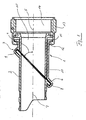
- FIG. 1 a section through an inventive end housing.
- FIG. 1 one recognizes the section through an inventive end housing. This has a closing element 1 and a subsequent to this cable guide tube 2.
- end element 1 and the cable guide tube 2 are made as two separate parts. These are interconnected by a flange unit 3.
- the flange unit shown in the example shown here has an installation angle 4 of approximately 45 ° relative to a central axis 5 of the end element 1.
- the Flanheitheit 3 consists on the one hand of a radially projecting circular disc 6, which is integrally formed in the darg Congressen example of the cable guide tube 2 and relative to the central axis 7 of the cable guide tube 2 forms an angle corresponding to the installation angle 4 of 45 ° in the present case.
- the circular disk 6 is formed like a collar and is of course not closed in its central region but contains a hole which does not affect the free cross section of the cable guide tube 2 in its dimensions.
- the circular disk 6 is received at its outer edge in an annular groove 8, which is provided as an integrally formed part of the flange unit 3 on the end element 1.
- This annular groove 8 has an outer edge 9, which is bent after insertion of the circular disc 6 in the annular groove 8 and thus closed, so that the circular disc 6 is held within the annular groove 8.
- this inwardly bent edge 9 may alternatively be provided an explosive or retaining ring.
- the annular groove 8 is provided at one end of an outer tube 10, which has a retaining flange 11 at its opposite end of the annular groove 8, which projects radially outwardly.
- This retaining flange 11 corresponds to a locking ring 12, which is provided in the radial direction inwardly projecting on a union nut 13.
- the molded locking ring 12 may alternatively be provided an explosive or retaining ring.
- Said union nut 13 is screwed in the direction of the central axis 5 of the end element 1 via a thread, which is not shown in the present example and belongs to a (also not shown) counterpart, such as a connector housing, a socket housing o.
- the fixing tube has at its end facing the circular disc 6 a chamfer, which corresponds to the mounting angle 4 in their angle.
Landscapes
- Engineering & Computer Science (AREA)
- Architecture (AREA)
- Civil Engineering (AREA)
- Structural Engineering (AREA)
- Insertion, Bundling And Securing Of Wires For Electric Apparatuses (AREA)
Abstract
Description
- Die Erfindung betrifft ein Endgehäuse für ein Kabel mit einem Abschlusselement und einem sich an dieses Abschlusselement anschließenden Kabelführungsrohr.
- Es ist bekannt, bei den verschiedensten Einsatzzwecken elektrische Kabel in der Nähe eines Abschlusselementes mit einem sich an dieses Abschlusselement anschließenden Kabelführungsrohr zu versehen. Unter einem Abschlusselement kann dabei sowohl ein Stecker oder eine Buchse verstanden werden oder aber auch eine Kabeldurchführung an einem Bauelement oder Bauteil. Das sich an dieses Abschlusselement anschließende Kabelführungsrohr kann eine Art Knickschutz für das Kabel sein oder aber auch ein Übergang von dem Abschlusselement in einen Kabelkanal o. ä.
- In gewissen Einsatzgebieten, wie beispielsweise im Verkehrsflugzeugbau werden unter den unterschiedlichsten Gesichtspunkten Kabel zum großen Teil in relativ starren Kabelkanälen verlegt. Wenn ein solcher Kabelkanal auf ein Gehäuse trifft, wird an dem Kabelkanal ein Endgehäuse vorgesehen, so dass das Kabel in das Gehäuse eintreten kann. Dieses Endgehäuse ist durch ein Kabelführungsrohr mit dem Kabelkanal verbunden und über ein Abschlusselement mit der Gehäusewand. Das Abschlusselement kann dabei sowohl einen Stecker oder eine Buchse als auch nur eine Kabeldurchführung aufweisen.
- Wenn nun die Gehäusewand nicht genau senkrecht zu der Mittelachse des Kabelkanals verläuft, muss ein Endgehäuse vorgesehen werden, durch das das Kabel geführt wird, das den Winkel zwischen der Gehäusewand und der Mittelachse des Kabelkanals ausgleicht.
- Es ist diesbezüglich üblich, für die sich ergebenden unterschiedlichen Winkel jeweils unterschiedliche Endgehäuse mit jeweils passenden Winkeln zwischen Abschlusselement und Kabelführungsrohr vorzusehen. Hierfür ist eine insgesamt umfangreiche Lagerhaltung von einer Vielzahl an Endstücken für unterschiedlichste Winkel notwendig.
- Selbst diese verhindert aber nicht, dass bei einer auch nur leichten Abweichung in dem zu überbrückenden Winkel kein exakt passendes Winkelstück vorhanden ist, um den Winkel ganz präzise ausgleichen zu können. Wenn ein mit einem Endgehäuse auszugleichender Winkel nur leicht von dem Winkel abweicht, für den ein spezielles Endgehäuse vorliegt, ist eine Montage des Endgehäuses ggf. nur mit einer unerwünschten Verspannung möglich.
- Aufgabe der vorliegenden Erfindung ist es daher, ein Endgehäuse für ein Kabel anzugeben, das derartige Nachteile vermeidet.
- Diese Aufgabe wird erfindungsgemäß dadurch gelöst, dass bei einem erfindungsgemäßen Endgehäuse das Abschlusselement und das Kabelführungsrohr als zwei Teile ausgeführt sind, die an einer gegenüber einer Mittelachse des Abschlusselementes geneigten Flanscheinheit miteinander verbunden sind.
- Der Vorteil der Erfindung liegt darin, dass es durch die geneigte Flanscheinheit möglich ist, Abschlusselement und Kabelführungsrohr gegeneinander zu verdrehen, wobei sich der Winkel zwischen der Mittelachse des Abschlusselementes und einer Mittelachse des Kabelführungsrohres verändert.
- Damit ist es möglich, das erfindungsgemäße Endgehäuse präzise auf die Anforderungen einzustellen, die je nach Einsatzstelle vorliegen.
- Als besonders vorteilhaft hat es sich erwiesen, wenn die Neigung, die die Flanscheinheit gegenüber der Mittelachse des Abschlusselementes aufweist, bei 45° liegt. Das Endgehäuse kann dadurch eingesetzt werden in allen Fällen, in denen der Winkel zwischen Mittelachse des Abschlusselementes und des Winkelementes des Kabelführungsrohres zwischen 0° und 90° liegt.
- Unter konstruktiven Gesichtspunkten wird vorgeschlagen, die Flanscheinheit verdrehbar auszugestalten und sie insbesondere mit einer in Radialrichtung vorspringenden Kreisscheibe an einem der genannten zwei Teile zu versehen und mit einer diese Kreisscheibe aufnehmenden Ringnut, die an dem anderen der genannten zwei Teile vorliegt.
- Es ist also erfindungsgemäß möglich, entweder am Abschlusselement oder auch an dem Kabelführungsrohr eine kreisförmige Flanschführung vorzusehen, die dann am Kabelführungsrohr oder aber am Abschlusselement in einer korrespondierenden Ringnut gehalten wird. Eine derartige Kreisscheiben/Ringnut-Kombination ermöglicht insbesondere auch eine stufenlose Veränderbarkeit des oben diskutierten Winkels zwischen seinen Grenzlagen.
- Um eine Fixierung des eingestellten Winkels zu erzielen, wird vorgeschlagen, in dem die Ringnut aufweisenden Teil ein gegen die Kreisscheibe drückbares Fixierrohr vorzusehen.
- Durch das Fixierrohr kann auf die Kreisscheibe ein Druck ausgeübt werden, durch den sie in ihrer Lage innerhalb der Ringnut festgehalten wird.
- Vorteilhafterweise wird das Fixierrohr an dem Abschlusselement vorgesehen und ist in eine am Abschlusselement vorgesehene Aufnahme verlängert. Die Aufnahme ist dabei an dem der Ringnut in Axialrichtung entgegengesetzten Ende des Abschlusselementes vorgesehen.
- Indem das Abschlusselement mit dieser Aufnahme an einem Gegenstück, sei es einem Stecker- oder Buchsenelement, sei es eine Gehäusedurchführung o. ä. befestigt wird, wird innerhalb der Aufnahme auf das Fixierrohr eine Kraft ausgeübt, die dann auf die Kreisscheibe übertragen wird und diese in ihrer Position innerhalb der sie umgebenden Ringnut festlegt.
- Weitere Vorteile und Merkmale der Erfindung ergeben sich aus der nachfolgenden Beschreibung eines Ausführungsbeispiels. Dabei zeigt
-
Figur 1 einen Schnitt durch ein erfindungsgemäßes Endgehäuse. - In
Figur 1 erkennt man den Schnitt durch ein erfindungsgemäßes Endgehäuse. Dieses weist ein Abschlusselement 1 und ein sich an dieses anschließendes Kabelführungsrohr 2 auf. - Es ist zu erkennen, dass das Abschlusselement 1 und das Kabelführungsrohr 2 als zwei separate Teile hergestellt sind. Diese sind durch eine Flanscheinheit 3 miteinander verbunden.
- Bei der im hier dargestellten Beispiel gezeigten Flanscheinheit weist diese einen Einbauwinkel 4 von etwa 45° zu einer Mittelachse 5 des Abschlusselementes 1 auf.
- Die Flanscheinheit 3 besteht zum einen aus einer in Radialrichtung vorspringenden Kreisscheibe 6, die im hier dargstellten Beispiel einstückig an dem Kabelführungsrohr 2 ausgebildet ist und gegenüber der Mittelachse 7 des Kabelführungsrohres 2 einen Winkel entsprechend dem Einbauwinkel 4 von im hier vorliegenden Fall 45° einschließt.
- Nur der guten Ordnung halber sei erwähnt, dass die Kreisscheibe 6 kragenartig ausgebildet ist und in ihrem mittleren Bereich selbstverständlich nicht geschlossen ist sondern ein Loch enthält, das in seinen Abmessungen den freien Querschnitt des Kabelführungsrohres 2 nicht beeinträchtigt.
- Die Kreisscheibe 6 ist an ihrem äußeren Rand in einer Ringnut 8 aufgenommen, die als einstückig angeformtes Teil der Flanscheinheit 3 am Abschlusselement 1 vorgesehen ist. Diese Ringnut 8 hat einen außen liegenden Rand 9, der nach Einsetzen der Kreisscheibe 6 in die Ringnut 8 umgebogen und damit verschlossen wird, so dass die Kreisscheibe 6 innerhalb der Ringnut 8 festgehalten wird. Anstelle dieses nach innen umgebogenen Randes 9 kann alternativ auch ein Spreng- bzw. Sicherungsring vorgesehen sein.
- Im hier dargestellten Beispiel ist die Ringnut 8 an einem Ende eines Außenrohres 10 vorgesehen, das an seinem der Ringnut 8 gegenüberliegenden Ende einen Halteflansch 11 aufweist, der radial nach außen vorspringt. Dieser Halteflansch 11 korrespondiert mit einem Arretierring 12, der in Radialrichtung nach innen vorstehenden an einer Überwurfmutter 13 vorgesehen ist. Auch hier kann statt des angeformten Arretierringes 12 alternativ ein Spreng- bzw. Sicherungsring vorgesehen sein.
- Die genannte Überwurfmutter 13 wird in Richtung der Mittelachse 5 des Abschlusselementes 1 über ein Gewinde geschraubt, das im hier vorliegenden Beispiel nicht dargestellt ist und zu einem (ebenfalls nicht dargestellten) Gegenstück gehört, beispielsweise einem Steckergehäuse, einem Buchsengehäuse o. ä.
- Dieses Gegenstück drückt dabei in der von der Überwurfmutter 13 in ihrem Inneren gebildeten Aufnahme 14 in Axialrichtung gegen ein Fixierrohr 15. Dieses wird in Axialrichtung innerhalb des Außenrohres 10 leicht verschoben und drückt mit seinem der Aufnahme 14 abgewandten Ende gegen die Kreisscheibe 6 des Kabelführungsrohres 2, die damit gegen den Rand 9 gedrückt wird. So wird die Kreisscheibe 6 in ihrer Stellung innerhalb der Ringnut 8 festgelegt.
- Es sei noch erwähnt, dass das Fixierrohr an seinem der Kreisscheibe 6 zugewandten Ende eine Abschrägung aufweist, die in ihrem Winkel dem Einbauwinkel 4 entspricht.
- Mit der hier beschriebenen Vorrichtung ist es also nun möglich, durch das Innere des Kabelführungsrohres 2 und des Fixierrohres 15 hindurch ein Kabel oder eine andere Art elektrischen Leiters zu der Aufnahme 14 des hier dargestellten Endgehäuses zu führen. Dabei ist über das Kabelführungsrohr 2 an seinem der Flanscheinheit 3 abgewandten Ende auch ein (hier nicht dargestelltes) Kabelkanalrohr schiebbar.
- Durch eine Verdrehung der Kreisscheibe 6 innerhalb der Ringnut 8 wird der in der
Figur 1 dargestellte geradlinige Verlauf zwischen der Mittelachse 7 des Kabelführungsrohres 2 und der Mittelachse 5 des Abschlusselementes 1 verändert. Damit kann mit dem hier dargestellten Endgehäuse eine beliebige Winkelstellung zwischen Abschlusselement 1 und Kabelführungsrohr 2 erzeugt werden. - Wird dann das Abschlusselement mit seiner Aufnahme 14 auf einen Stecker, ein Gewinderohr o. ä. aufgesetzt, so drückt dieses dann das innen liegende Fixierrohr 15 gegen die verdrehte Kreisscheibe 6 und fixiert so die gewünschte Winkelstellung.
- Es ist somit möglich, unterschiedliche Winkelstellungen mit demselben Endgehäuse zu erzeugen und es ist nicht mehr notwendig, für unterschiedliche Winkel eine Vielzahl von unterschiedlichen Endgehäusen vorzusehen.
- Es sei an dieser Stelle noch darauf hingewiesen, dass die hier dargestellte Bauform die bevorzugte Ausführungsform ist. Es ist aber auch möglich, die Kreisscheibe 6 am Abschlusselement 1 vorzusehen und die korrespondierende Ringnut 8 demgemäß am Kabelführungsrohr 2. Grundsätzlich ist auch eine Ausführungsform ohne Fixierrohr 15 möglich. In diesem Fall kann eine Fixierung der Kreisscheibe 6 innerhalb der Ringnut 8 beispielsweise auch durch eine Verlötung, Verklebung oder ähnliches erreicht werden.
Claims (5)
- Endgehäuse für ein Kabel
mit einem Abschlusselement (1) und einem sich an dieses anschließenden Kabelführungsrohr (2),
dadurch gekennzeichnet,
dass das Abschlusselement (1) und das Kabelführungsrohr (2) als zwei Teile ausgeführt sind, die an einer gegenüber einer Mittelachse (5) des Abschlusselementes (1) geneigten Flanscheinheit (3) miteinander verbunden sind. - Endgehäuse gemäß Anspruch 1,
dadurch gekennzeichnet,
dass die Neigung der Flanscheinheit (3) gegenüber der Mittelachse (5) etwa 45° beträgt. - Endgehäuse gemäß Anspruch 1,
dadurch gekennzeichnet,
dass die Flanscheinheit (3) eine in Radialrichtung vorspringende Kreisscheibe (6) an einem der genannten zwei Teile sowie eine diese aufnehmende Ringnut (8) am anderen der genannten zwei Teile aufweist. - Endgehäuse gemäß Anspruch 3,
dadurch gekennzeichnet,
dass in dem anderen Teil ein gegen die Kreisscheibe (6) drückbares Fixierrohr (15) vorgesehen ist. - Endgehäuse gemäß Anspruch 5,
dadurch gekennzeichnet,
dass das andere Teil das Abschlusselement (1) ist und sich das Fixierrohr (15) bis in eine Aufnahme (14) des Abschlusselementes (1) erstreckt.
Applications Claiming Priority (1)
| Application Number | Priority Date | Filing Date | Title |
|---|---|---|---|
| DE102009033778A DE102009033778A1 (de) | 2009-07-17 | 2009-07-17 | Endgehäuse für ein elektrisches Kabel |
Publications (3)
| Publication Number | Publication Date |
|---|---|
| EP2276130A2 true EP2276130A2 (de) | 2011-01-19 |
| EP2276130A3 EP2276130A3 (de) | 2014-10-29 |
| EP2276130B1 EP2276130B1 (de) | 2017-08-09 |
Family
ID=43014475
Family Applications (1)
| Application Number | Title | Priority Date | Filing Date |
|---|---|---|---|
| EP10006752.9A Not-in-force EP2276130B1 (de) | 2009-07-17 | 2010-06-30 | Endgehäuse für ein elektrisches Kabel |
Country Status (2)
| Country | Link |
|---|---|
| EP (1) | EP2276130B1 (de) |
| DE (1) | DE102009033778A1 (de) |
Cited By (3)
| Publication number | Priority date | Publication date | Assignee | Title |
|---|---|---|---|---|
| US20140300097A1 (en) * | 2013-04-05 | 2014-10-09 | Jeffrey Krause | Conduit stub-up connector assembly and method |
| US9391393B2 (en) | 2012-11-08 | 2016-07-12 | Delphi Technologies, Inc. | Connector backshell having multiple cable exit configurations |
| WO2025222075A1 (en) * | 2024-04-18 | 2025-10-23 | Mjm Industries, Inc. | Electrical connector system |
Family Cites Families (4)
| Publication number | Priority date | Publication date | Assignee | Title |
|---|---|---|---|---|
| DE1150424B (de) * | 1958-02-17 | 1963-06-20 | Elbtalwerk Heidenau Veb | Kabeleinfuehrungskasten mit mindestens einer seitlich angeordneten Anbauflaeche fuer den kontinuierlich oder stufenweise drehverstellbaren Anbau mindestens eines Einfuehrungsstutzens, insbesondere fuer elektrische Maschinen |
| DE3439784C2 (de) * | 1984-10-31 | 1986-09-04 | Endress U. Hauser Gmbh U. Co, 7867 Maulburg | Anordnung zur Einführung eines Kabels in ein Gehäuse |
| US5064226A (en) * | 1990-05-30 | 1991-11-12 | Hubbell Incorporated | Nonmetallic conduit fitting with transverse biasing abutments |
| US6932390B1 (en) * | 2002-10-28 | 2005-08-23 | Arlington Industries, Inc. | Swivel fitting |
-
2009
- 2009-07-17 DE DE102009033778A patent/DE102009033778A1/de not_active Withdrawn
-
2010
- 2010-06-30 EP EP10006752.9A patent/EP2276130B1/de not_active Not-in-force
Non-Patent Citations (1)
| Title |
|---|
| None |
Cited By (3)
| Publication number | Priority date | Publication date | Assignee | Title |
|---|---|---|---|---|
| US9391393B2 (en) | 2012-11-08 | 2016-07-12 | Delphi Technologies, Inc. | Connector backshell having multiple cable exit configurations |
| US20140300097A1 (en) * | 2013-04-05 | 2014-10-09 | Jeffrey Krause | Conduit stub-up connector assembly and method |
| WO2025222075A1 (en) * | 2024-04-18 | 2025-10-23 | Mjm Industries, Inc. | Electrical connector system |
Also Published As
| Publication number | Publication date |
|---|---|
| EP2276130B1 (de) | 2017-08-09 |
| EP2276130A3 (de) | 2014-10-29 |
| DE102009033778A1 (de) | 2011-01-20 |
Similar Documents
| Publication | Publication Date | Title |
|---|---|---|
| EP2649689B1 (de) | Vorrichtung zur fixierung eines kabels an einem kabelabgangsstutzen | |
| EP3132506B1 (de) | Kabelabgang | |
| DE102013109653B4 (de) | Steckverbindergehäuse und Verfahren zum Öffnen seines Kabelabgangs | |
| DE102014104446A1 (de) | Elektrischer Steckverbinder | |
| WO2015185511A2 (de) | Elektrisches gerät | |
| EP2532061B1 (de) | Elektrisches gerät mit einer durchführung eines kabels durch eine gehäusewand | |
| EP2264848A1 (de) | Kabelverschraubung | |
| EP2224544A1 (de) | Kabelordnender Einsatz für Steckverbinder | |
| DE102008057473B4 (de) | Kabeldurchführung | |
| EP3301770B1 (de) | Kabelverschraubung | |
| DE102014200133A1 (de) | Vorrichtung zur Fixierung einer elektrischen Leitung in einem Stecker, Stecker für eine elektrische Leitung sowie elektrisches Kabel | |
| EP2664042B1 (de) | Vorrichtung zur fixierung eines kabels an einen kabelabgangsstutzen | |
| DE102008019165A1 (de) | Kabelverschraubung, insbesondere für ein Abschirm- oder Erdungskabel | |
| EP2276130B1 (de) | Endgehäuse für ein elektrisches Kabel | |
| DE102011108123A1 (de) | Kabelanschlussbauteil sowie Kabelanschlusseinrichtung und Kabelverbindungseinrichtung mit einem Kabelanschlussbauteil | |
| DE102009033948A1 (de) | Kabel- oder Schlauchverschraubung | |
| EP1610049A2 (de) | Schlauchverbindungssystem für einen beheizbaren Schlauch | |
| DE102008011978B4 (de) | Verschraubung für abgedichtete Leitungsdurchführungen | |
| EP3183787A1 (de) | Elektrisches gerät | |
| DE4030765A1 (de) | Armatur | |
| DE202008002915U1 (de) | Verschraubung für abgedichtete Leitungsdurchführungen | |
| DE29722987U1 (de) | Kabelverschraubung für Kabel mit Abschirmummantelung | |
| EP2293390A1 (de) | Elektrische Verbindung zwischen dem Gehäuse eines Wickelgutes und einer Platine | |
| EP1303020B1 (de) | Elektrische Verkabelung mit Zugentlastung | |
| WO2018122048A1 (de) | Steckverbindungssystem und aufsteckwinkel dafür |
Legal Events
| Date | Code | Title | Description |
|---|---|---|---|
| PUAI | Public reference made under article 153(3) epc to a published international application that has entered the european phase |
Free format text: ORIGINAL CODE: 0009012 |
|
| AK | Designated contracting states |
Kind code of ref document: A2 Designated state(s): AL AT BE BG CH CY CZ DE DK EE ES FI FR GB GR HR HU IE IS IT LI LT LU LV MC MK MT NL NO PL PT RO SE SI SK SM TR |
|
| AX | Request for extension of the european patent |
Extension state: BA ME RS |
|
| PUAL | Search report despatched |
Free format text: ORIGINAL CODE: 0009013 |
|
| AK | Designated contracting states |
Kind code of ref document: A3 Designated state(s): AL AT BE BG CH CY CZ DE DK EE ES FI FR GB GR HR HU IE IS IT LI LT LU LV MC MK MT NL NO PL PT RO SE SI SK SM TR |
|
| AX | Request for extension of the european patent |
Extension state: BA ME RS |
|
| RIC1 | Information provided on ipc code assigned before grant |
Ipc: H02G 3/06 20060101ALI20140924BHEP Ipc: H02G 3/04 20060101AFI20140924BHEP |
|
| 17P | Request for examination filed |
Effective date: 20150110 |
|
| RBV | Designated contracting states (corrected) |
Designated state(s): AL AT BE BG CH CY CZ DE DK EE ES FI FR GB GR HR HU IE IS IT LI LT LU LV MC MK MT NL NO PL PT RO SE SI SK SM TR |
|
| GRAP | Despatch of communication of intention to grant a patent |
Free format text: ORIGINAL CODE: EPIDOSNIGR1 |
|
| INTG | Intention to grant announced |
Effective date: 20170221 |
|
| GRAS | Grant fee paid |
Free format text: ORIGINAL CODE: EPIDOSNIGR3 |
|
| GRAA | (expected) grant |
Free format text: ORIGINAL CODE: 0009210 |
|
| AK | Designated contracting states |
Kind code of ref document: B1 Designated state(s): AL AT BE BG CH CY CZ DE DK EE ES FI FR GB GR HR HU IE IS IT LI LT LU LV MC MK MT NL NO PL PT RO SE SI SK SM TR |
|
| REG | Reference to a national code |
Ref country code: GB Ref legal event code: FG4D Free format text: NOT ENGLISH |
|
| REG | Reference to a national code |
Ref country code: CH Ref legal event code: EP Ref country code: AT Ref legal event code: REF Ref document number: 917796 Country of ref document: AT Kind code of ref document: T Effective date: 20170815 |
|
| REG | Reference to a national code |
Ref country code: IE Ref legal event code: FG4D Free format text: LANGUAGE OF EP DOCUMENT: GERMAN |
|
| REG | Reference to a national code |
Ref country code: DE Ref legal event code: R096 Ref document number: 502010013959 Country of ref document: DE |
|
| REG | Reference to a national code |
Ref country code: NL Ref legal event code: MP Effective date: 20170809 |
|
| REG | Reference to a national code |
Ref country code: LT Ref legal event code: MG4D |
|
| PG25 | Lapsed in a contracting state [announced via postgrant information from national office to epo] |
Ref country code: SE Free format text: LAPSE BECAUSE OF FAILURE TO SUBMIT A TRANSLATION OF THE DESCRIPTION OR TO PAY THE FEE WITHIN THE PRESCRIBED TIME-LIMIT Effective date: 20170809 Ref country code: LT Free format text: LAPSE BECAUSE OF FAILURE TO SUBMIT A TRANSLATION OF THE DESCRIPTION OR TO PAY THE FEE WITHIN THE PRESCRIBED TIME-LIMIT Effective date: 20170809 Ref country code: FI Free format text: LAPSE BECAUSE OF FAILURE TO SUBMIT A TRANSLATION OF THE DESCRIPTION OR TO PAY THE FEE WITHIN THE PRESCRIBED TIME-LIMIT Effective date: 20170809 Ref country code: NO Free format text: LAPSE BECAUSE OF FAILURE TO SUBMIT A TRANSLATION OF THE DESCRIPTION OR TO PAY THE FEE WITHIN THE PRESCRIBED TIME-LIMIT Effective date: 20171109 Ref country code: NL Free format text: LAPSE BECAUSE OF FAILURE TO SUBMIT A TRANSLATION OF THE DESCRIPTION OR TO PAY THE FEE WITHIN THE PRESCRIBED TIME-LIMIT Effective date: 20170809 Ref country code: HR Free format text: LAPSE BECAUSE OF FAILURE TO SUBMIT A TRANSLATION OF THE DESCRIPTION OR TO PAY THE FEE WITHIN THE PRESCRIBED TIME-LIMIT Effective date: 20170809 |
|
| PG25 | Lapsed in a contracting state [announced via postgrant information from national office to epo] |
Ref country code: GR Free format text: LAPSE BECAUSE OF FAILURE TO SUBMIT A TRANSLATION OF THE DESCRIPTION OR TO PAY THE FEE WITHIN THE PRESCRIBED TIME-LIMIT Effective date: 20171110 Ref country code: PL Free format text: LAPSE BECAUSE OF FAILURE TO SUBMIT A TRANSLATION OF THE DESCRIPTION OR TO PAY THE FEE WITHIN THE PRESCRIBED TIME-LIMIT Effective date: 20170809 Ref country code: BG Free format text: LAPSE BECAUSE OF FAILURE TO SUBMIT A TRANSLATION OF THE DESCRIPTION OR TO PAY THE FEE WITHIN THE PRESCRIBED TIME-LIMIT Effective date: 20171109 Ref country code: ES Free format text: LAPSE BECAUSE OF FAILURE TO SUBMIT A TRANSLATION OF THE DESCRIPTION OR TO PAY THE FEE WITHIN THE PRESCRIBED TIME-LIMIT Effective date: 20170809 Ref country code: LV Free format text: LAPSE BECAUSE OF FAILURE TO SUBMIT A TRANSLATION OF THE DESCRIPTION OR TO PAY THE FEE WITHIN THE PRESCRIBED TIME-LIMIT Effective date: 20170809 Ref country code: IS Free format text: LAPSE BECAUSE OF FAILURE TO SUBMIT A TRANSLATION OF THE DESCRIPTION OR TO PAY THE FEE WITHIN THE PRESCRIBED TIME-LIMIT Effective date: 20171209 |
|
| PG25 | Lapsed in a contracting state [announced via postgrant information from national office to epo] |
Ref country code: CZ Free format text: LAPSE BECAUSE OF FAILURE TO SUBMIT A TRANSLATION OF THE DESCRIPTION OR TO PAY THE FEE WITHIN THE PRESCRIBED TIME-LIMIT Effective date: 20170809 Ref country code: RO Free format text: LAPSE BECAUSE OF FAILURE TO SUBMIT A TRANSLATION OF THE DESCRIPTION OR TO PAY THE FEE WITHIN THE PRESCRIBED TIME-LIMIT Effective date: 20170809 Ref country code: DK Free format text: LAPSE BECAUSE OF FAILURE TO SUBMIT A TRANSLATION OF THE DESCRIPTION OR TO PAY THE FEE WITHIN THE PRESCRIBED TIME-LIMIT Effective date: 20170809 |
|
| REG | Reference to a national code |
Ref country code: DE Ref legal event code: R097 Ref document number: 502010013959 Country of ref document: DE |
|
| PG25 | Lapsed in a contracting state [announced via postgrant information from national office to epo] |
Ref country code: EE Free format text: LAPSE BECAUSE OF FAILURE TO SUBMIT A TRANSLATION OF THE DESCRIPTION OR TO PAY THE FEE WITHIN THE PRESCRIBED TIME-LIMIT Effective date: 20170809 Ref country code: SK Free format text: LAPSE BECAUSE OF FAILURE TO SUBMIT A TRANSLATION OF THE DESCRIPTION OR TO PAY THE FEE WITHIN THE PRESCRIBED TIME-LIMIT Effective date: 20170809 Ref country code: SM Free format text: LAPSE BECAUSE OF FAILURE TO SUBMIT A TRANSLATION OF THE DESCRIPTION OR TO PAY THE FEE WITHIN THE PRESCRIBED TIME-LIMIT Effective date: 20170809 Ref country code: IT Free format text: LAPSE BECAUSE OF FAILURE TO SUBMIT A TRANSLATION OF THE DESCRIPTION OR TO PAY THE FEE WITHIN THE PRESCRIBED TIME-LIMIT Effective date: 20170809 |
|
| PLBE | No opposition filed within time limit |
Free format text: ORIGINAL CODE: 0009261 |
|
| STAA | Information on the status of an ep patent application or granted ep patent |
Free format text: STATUS: NO OPPOSITION FILED WITHIN TIME LIMIT |
|
| REG | Reference to a national code |
Ref country code: FR Ref legal event code: PLFP Year of fee payment: 9 |
|
| 26N | No opposition filed |
Effective date: 20180511 |
|
| PGFP | Annual fee paid to national office [announced via postgrant information from national office to epo] |
Ref country code: DE Payment date: 20180625 Year of fee payment: 9 |
|
| PG25 | Lapsed in a contracting state [announced via postgrant information from national office to epo] |
Ref country code: SI Free format text: LAPSE BECAUSE OF FAILURE TO SUBMIT A TRANSLATION OF THE DESCRIPTION OR TO PAY THE FEE WITHIN THE PRESCRIBED TIME-LIMIT Effective date: 20170809 |
|
| PGFP | Annual fee paid to national office [announced via postgrant information from national office to epo] |
Ref country code: FR Payment date: 20180625 Year of fee payment: 9 |
|
| PG25 | Lapsed in a contracting state [announced via postgrant information from national office to epo] |
Ref country code: MT Free format text: LAPSE BECAUSE OF FAILURE TO SUBMIT A TRANSLATION OF THE DESCRIPTION OR TO PAY THE FEE WITHIN THE PRESCRIBED TIME-LIMIT Effective date: 20170809 |
|
| PGFP | Annual fee paid to national office [announced via postgrant information from national office to epo] |
Ref country code: GB Payment date: 20180626 Year of fee payment: 9 |
|
| REG | Reference to a national code |
Ref country code: CH Ref legal event code: PL |
|
| REG | Reference to a national code |
Ref country code: BE Ref legal event code: MM Effective date: 20180630 |
|
| PG25 | Lapsed in a contracting state [announced via postgrant information from national office to epo] |
Ref country code: MC Free format text: LAPSE BECAUSE OF FAILURE TO SUBMIT A TRANSLATION OF THE DESCRIPTION OR TO PAY THE FEE WITHIN THE PRESCRIBED TIME-LIMIT Effective date: 20170809 Ref country code: LU Free format text: LAPSE BECAUSE OF NON-PAYMENT OF DUE FEES Effective date: 20180630 |
|
| REG | Reference to a national code |
Ref country code: IE Ref legal event code: MM4A |
|
| PG25 | Lapsed in a contracting state [announced via postgrant information from national office to epo] |
Ref country code: IE Free format text: LAPSE BECAUSE OF NON-PAYMENT OF DUE FEES Effective date: 20180630 Ref country code: CH Free format text: LAPSE BECAUSE OF NON-PAYMENT OF DUE FEES Effective date: 20180630 Ref country code: LI Free format text: LAPSE BECAUSE OF NON-PAYMENT OF DUE FEES Effective date: 20180630 |
|
| PG25 | Lapsed in a contracting state [announced via postgrant information from national office to epo] |
Ref country code: BE Free format text: LAPSE BECAUSE OF NON-PAYMENT OF DUE FEES Effective date: 20180630 |
|
| REG | Reference to a national code |
Ref country code: AT Ref legal event code: MM01 Ref document number: 917796 Country of ref document: AT Kind code of ref document: T Effective date: 20180630 |
|
| PG25 | Lapsed in a contracting state [announced via postgrant information from national office to epo] |
Ref country code: AT Free format text: LAPSE BECAUSE OF NON-PAYMENT OF DUE FEES Effective date: 20180630 |
|
| REG | Reference to a national code |
Ref country code: DE Ref legal event code: R119 Ref document number: 502010013959 Country of ref document: DE |
|
| GBPC | Gb: european patent ceased through non-payment of renewal fee |
Effective date: 20190630 |
|
| PG25 | Lapsed in a contracting state [announced via postgrant information from national office to epo] |
Ref country code: TR Free format text: LAPSE BECAUSE OF FAILURE TO SUBMIT A TRANSLATION OF THE DESCRIPTION OR TO PAY THE FEE WITHIN THE PRESCRIBED TIME-LIMIT Effective date: 20170809 |
|
| PG25 | Lapsed in a contracting state [announced via postgrant information from national office to epo] |
Ref country code: DE Free format text: LAPSE BECAUSE OF NON-PAYMENT OF DUE FEES Effective date: 20200101 Ref country code: GB Free format text: LAPSE BECAUSE OF NON-PAYMENT OF DUE FEES Effective date: 20190630 |
|
| PG25 | Lapsed in a contracting state [announced via postgrant information from national office to epo] |
Ref country code: PT Free format text: LAPSE BECAUSE OF FAILURE TO SUBMIT A TRANSLATION OF THE DESCRIPTION OR TO PAY THE FEE WITHIN THE PRESCRIBED TIME-LIMIT Effective date: 20170809 Ref country code: HU Free format text: LAPSE BECAUSE OF FAILURE TO SUBMIT A TRANSLATION OF THE DESCRIPTION OR TO PAY THE FEE WITHIN THE PRESCRIBED TIME-LIMIT; INVALID AB INITIO Effective date: 20100630 |
|
| PG25 | Lapsed in a contracting state [announced via postgrant information from national office to epo] |
Ref country code: FR Free format text: LAPSE BECAUSE OF NON-PAYMENT OF DUE FEES Effective date: 20190630 Ref country code: CY Free format text: LAPSE BECAUSE OF FAILURE TO SUBMIT A TRANSLATION OF THE DESCRIPTION OR TO PAY THE FEE WITHIN THE PRESCRIBED TIME-LIMIT Effective date: 20170809 Ref country code: MK Free format text: LAPSE BECAUSE OF NON-PAYMENT OF DUE FEES Effective date: 20170809 |
|
| PG25 | Lapsed in a contracting state [announced via postgrant information from national office to epo] |
Ref country code: AL Free format text: LAPSE BECAUSE OF FAILURE TO SUBMIT A TRANSLATION OF THE DESCRIPTION OR TO PAY THE FEE WITHIN THE PRESCRIBED TIME-LIMIT Effective date: 20170809 |