EP2275362B1 - Durchlaufregal mit einem Stützrahmen zur Befestigung einer Föderleiste - Google Patents
Durchlaufregal mit einem Stützrahmen zur Befestigung einer Föderleiste Download PDFInfo
- Publication number
- EP2275362B1 EP2275362B1 EP10166884A EP10166884A EP2275362B1 EP 2275362 B1 EP2275362 B1 EP 2275362B1 EP 10166884 A EP10166884 A EP 10166884A EP 10166884 A EP10166884 A EP 10166884A EP 2275362 B1 EP2275362 B1 EP 2275362B1
- Authority
- EP
- European Patent Office
- Prior art keywords
- support frame
- recess
- storage rack
- conveyor
- conveyor bar
- Prior art date
- Legal status (The legal status is an assumption and is not a legal conclusion. Google has not performed a legal analysis and makes no representation as to the accuracy of the status listed.)
- Not-in-force
Links
- 238000003860 storage Methods 0.000 title claims description 20
- 238000004519 manufacturing process Methods 0.000 claims description 8
- 238000000034 method Methods 0.000 claims description 8
- 238000004080 punching Methods 0.000 claims description 8
- 238000005520 cutting process Methods 0.000 claims description 5
- 238000005070 sampling Methods 0.000 description 11
- 238000009434 installation Methods 0.000 description 5
- 239000002699 waste material Substances 0.000 description 3
- 238000010586 diagram Methods 0.000 description 2
- 238000003780 insertion Methods 0.000 description 2
- 230000037431 insertion Effects 0.000 description 2
- 238000010276 construction Methods 0.000 description 1
- 230000001419 dependent effect Effects 0.000 description 1
- 230000005484 gravity Effects 0.000 description 1
- 230000002452 interceptive effect Effects 0.000 description 1
- 239000000314 lubricant Substances 0.000 description 1
- 239000004570 mortar (masonry) Substances 0.000 description 1
Images




Classifications
-
- B—PERFORMING OPERATIONS; TRANSPORTING
- B65—CONVEYING; PACKING; STORING; HANDLING THIN OR FILAMENTARY MATERIAL
- B65G—TRANSPORT OR STORAGE DEVICES, e.g. CONVEYORS FOR LOADING OR TIPPING, SHOP CONVEYOR SYSTEMS OR PNEUMATIC TUBE CONVEYORS
- B65G1/00—Storing articles, individually or in orderly arrangement, in warehouses or magazines
- B65G1/02—Storage devices
- B65G1/023—Arrangements of article supporting rollers on racks
Definitions
- the invention relates to a flow rack with a support frame for attaching a conveyor bar, a method for producing a conveyor bar and a support frame for a flow shelf and a method of assembling a flow shelf with a support frame for attachment of conveyor bars.
- a flow shelf usually has a task side and a removal side. On the removal side, the items in the flow rack can be removed. On the feed side, they are automatically or manually refilled into the flow rack.
- the conveyor rails of the flow shelf extend from the task side to the unloading side with a negative slope. Gravity ensures that the goods stored in the rack move from the feed side to the unloading side.
- a flow shelf is provided with a support frame for attachment of conveyor strips, which allows easier attachment of the conveyor bars.
- the support frame has a support frame element extending from an object side to a removal side, the support frame element having a first fastening element on the application side.
- the first fastening element may be, for example, a tab.
- the first fastening element is designed to form a positive connection with one of the conveyor strips. For example, this positive connection can be realized by engaging the tab in a recess on the conveyor bar.
- a second fastening element serves to form a clamping connection on the removal side between the support frame element and the conveyor bar.
- the installation of the conveyor strips in the flow shelf is simplified. It is possible to insert the conveyor bar from one side into the flow shelf and with the support frame element connect to.
- the attachment of the conveyor bar on the support frame element on the task side by a tab on the support frame element, which engages in a recess on the conveyor bar.
- the attachment of the conveyor bar on the support frame element is preferably carried out by a clip which produces a clamping connection between the conveyor bar and the support frame element.
- the conveyor bar can therefore be mounted from the unloading side, in which it is pushed from the sampling side to the task side, where the tab of the support frame element engages in the recess of the conveyor bar. At the removal side, the conveyor bar is then fastened by means of the clip on the support frame element.
- This type of attachment of the conveyor bar on the support frame element is advantageous because the assembly of the conveyor bars can be done in a raised shelf from one side. It is thus made possible to mount the conveyor strips only at the end of the construction of the flow rack. This is advantageous because other work - by e.g. Mortar - the rollers can not pollute. Also, an exchange of the conveyor bars is simplified because they can be easily removed from the sampling side and can be replaced by new conveyor bars. As part of the removal or installation of a conveyor bar, it is not necessary for the fitter to reach the task side of the flow rack. Any automatic refill devices installed there may remain on the task side without interfering with the mounting of the conveyor rails. On a scaffold when attaching or dismounting the conveyor rails on the task side can be omitted.
- the support frame element is formed angular. This is advantageous because it ensures greater stability.
- the support frame element serves as a support for a conveyor bar.
- the conveyor bar is thus on the support frame element.
- the conveyor bar on a first recess on the task side.
- the first fastening element is designed to engage in the first recess.
- the first fastener is a tab on the support frame member and the first recess on the conveyor bar is formed so that it enters into a positive connection with the tab.
- the conveyor bar can be attached from the sampling side of the support frame element.
- the first fastening element is designed as a tab. This is advantageous because the tab with the first recess enters into a positive connection. Characterized in that the first recess is tapered from the task side to the removal side, the insertion of the tab is facilitated in the recess.
- the support frame element has a second recess on the removal side, which is designed to receive a second fastening element.
- the second fastening element may for example be a fastening clip.
- the second fastening element is performed according to embodiments of the invention by the second recess on the removal side of the support frame member and serves to form a clamping connection with the conveyor bar.
- the mounting clamp engages from below through the support frame element and the conveyor bar is clamped from above into the mounting clamp.
- Other mounting clamps can - for example on conveyor bars from a length of 2m - be arranged between the task and the removal side to achieve an even more stable attachment of the conveyor bar.
- the support frame element has at least one further tab, wherein the tabs are arranged equidistantly.
- Each tab stands from a bearing surface of the support frame element.
- the support surface is the surface on which rests the attached to the support frame element conveyor bar.
- An equidistant arrangement of identical tabs on the support frame member has the advantage of simpler and less expensive manufacture.
- the support frame elements are produced in the form of an endless profile. In this support frame element endless profile, the tabs are now punched, for example, using a punching tool. In an equidistant arrangement of the identical tabs, the tabs are regularly punched, for example, from the punch into the support frame element endless profile. Later different length support frame elements can be made from the support frame element endless profile.
- the conveyor bar has a third recess into which protrudes a second tab of the support frame member in the mounting position.
- the third recess has a shape resulting from the shape of the first recess and the mirrored shape of the first recess.
- the third recess in the conveyor bar is advantageous because the second tab projects into it.
- the third recess makes it possible that the support surface of the support frame element is flat and the conveyor bar does not rest on the second tab.
- the shape of the third recess is advantageous since the first recess and the third recess can be produced by the same tool. This can be for example a punching tool.
- both recesses can be produced by equidistant punching the third recess in a conveyor strip endless profile.
- the conveyor strip endless profile is severed at the point at which the first recess is to be arranged.
- the conveyor bar endless profile is in the middle of a third recess cut through, resulting in a first recess.
- the end of this so produced conveyor bar with the first recess preferably represents the end of the conveyor bar on the task side.
- a walk-in stage is arranged on the removal side of the flow shelf.
- a walk-in stage is usually used to allow the user to remove goods from higher storage locations of the flow rack.
- Such a stage is advantageous for embodiments of the invention, since it can also be used for the assembly of the conveyor bars on the flow shelf. So no scaffolding on the removal side for mounting the conveyor rails must be built.
- an automatic feeder is arranged on the feed side of the flow rack.
- An automatic feed is advantageous because it automatically tracks the goods in the flow shelf. Characterized in that according to embodiments of the invention, the conveyor bars can be mounted only from the sampling side and access to the task side is not needed, the automatic feed is not affected by the installation or replacement of the conveyor bars.
- the recesses and fastening elements of the conveyor strips and supporting frame elements were punched out.
- This is advantageous because it allows a simple and cost-effective production of the support frame elements and conveyor bars.
- conveyor strips and Stüfizrahmenimplantation are produced in the form of endless profiles, in which then the recesses and fasteners are punched.
- the first recess and the first fastening element are arranged in a range of 5 to 40 mm before the end of the flow shelf on the feed side.
- the second recess and the second fastening element are arranged in a range of 5 to 300 mm before the end of the flow shelf on the discharge side.
- At least one further fastening clamp for fastening the conveyor bar to the support frame element is arranged between the removal side and the task side.
- the attachment of the conveyor bar using the mounting clamp on the support frame element takes place here on the same principle as on the sampling side.
- the mounting clamp is pushed through a recess in the support frame member and the conveyor bar is clamped into it, so that a clamping connection is formed.
- the conveyor bar is designed as a roller bar.
- the roller bar consists of several transversely to the conveying direction arranged rollers which are rotatably mounted in a roller bar profile.
- General cargo can be transported from the task to the removal side via the rollers arranged in this way.
- the conveyor bar is a slide rail.
- the slide rail is coated with a plastic having a low coefficient of friction, which makes it easier to slide piece goods. Further, for example, the friction coefficient can be reduced by lubricants.
- the slide rail is mounted at a 10-30% pitch, although shallower or steeper slopes can be achieved.
- the conveyor bar on a conveyor belt is arranged so that it is designed for transporting piece goods from the task to the removal side. It is not necessary but possible that the conveyor belt occupies the entire width of the conveyor bar.
- the conveyor belt can also extend only over part of the conveyor bar.
- the conveyor belt has a width of 1-10 cm, although smaller or larger widths can be realized.
- the conveyor bar is designed so that gears transport the piece goods from the task to the removal side.
- gears transport the piece goods from the task to the removal side.
- a plurality of gears is arranged on the conveyor bar, which transport the cargo by grab with their teeth from below into the cargo.
- the gears are rotatably mounted, the piece goods can be transported from the task to the removal side with a rotation of the gears.
- conveyor bar can be understood any means that is designed to transport piece goods from the task to the removal side.
- a conveyor for general cargo can be formed from a single conveyor bar. This is preferably the case when the width of the piece goods to be transported coincides with the width of the conveyor bar or when the width of the piece goods to be transported is smaller than the width of the conveyor bar.
- a conveyor for general cargo can also be formed from two or more conveyor strips. This is preferably the case when the width of the piece goods to be transported exceeds the width of a conveyor bar
- the invention relates to a method for producing a conveyor bar and a support frame for a flow shelf.
- the method comprises punching equidistant third recesses into a conveyor bar endless profile, punching out equally equidistant second recesses and first fixing elements into a support frame element endless profile.
- the distances between the third recesses are preferably equal to the distances between the first fastening elements. This is advantageous since each first fastening element can thus be passed through a third recess.
- the method comprises cutting the endless profiles to the desired length.
- a third recess of the conveyor strip endless profile is divided on the task side when cutting in the middle, so that a first recess arises.
- this end of the conveyor bar represents the end of the task side.
- the invention in another aspect, relates to an assembly method for a flow shelf.
- the mounting method comprises the mounting of the support frame with support frame elements, the mounting of a walkable stage on the removal side, placing at least one conveyor bar on a support frame element, pushing the conveyor bar on the support frame member to the first recess of the conveyor bar a positive connection with the first fastener of Support frame member forms and pinching the conveyor bar in the second fastener.
- the assembly of the conveyor bar is preferably carried out exclusively via the removal side. Through the walk-in stage, the flow shelf is easily accessible at any point from the sampling side, which simplifies the installation of the conveyor bars.
- FIG. 1 shows a schematic representation of a flow shelf 100 with a plurality of inventive conveyor strips 102 and a plurality of support frame 104 according to the invention.
- the flow shelf 100 has a removal side 106 and a task side 108. On the removal side 106 is a stage 110. On the task side 108 is an automatic feeder 112. Further, the flow shelf 100 has a plurality of support frame elements 114. On the feed side there is an automatic feeder 112 for the automatic refilling of the flow shelf 100.
- the assembly of the conveyor strips 102 can be carried out completely from the removal side 106. For the higher conveyor bars, this can be done from the stage 110. Access to the support frame 104 from the task side 108 is not required. This leaves the automatic feeder 112 of an assembly or renewal of the conveyor strips 102 untouched.
- the person 115 on the stage 110 mounted a conveyor bar 102 on a support frame member 114.
- the conveyor bar 102 is first pushed through to the back to task side 108, where, for example, a tab of the support frame member 114 with a recess in the conveyor bar 102 produces a positive connection.
- the conveyor bar 102 is attached by means of a clamping connection on the support frame member 114.
- a removal edge 117 is arranged on the support frame 104, which prevents that piece goods fall out of the flow shelf. Furthermore, it is prevented by the removal edge 117 that the conveyor bar 102 slips down to the front of the removal side 106 of the support frame member 114. Rear of the task side 108, the conveyor bar 102 is thus secured, for example, with a tab on the support frame member 114 and a recess in the conveyor bar 102 and the front of the removal side 106 is prevented by the removal edge 117 from slipping out. Between these two fastenings, a clamping connection between the conveyor bar 102 and support frame member 114 is made by means of a fastener.
- FIG. 2a shows a schematic representation of the plan view of an inventive support frame member 114. At the support frame member tabs 116 and recesses 118 are arranged. The interruption in the conveyor bar 102 shows that a portion of the conveyor bar 102 is not shown.
- FIG. 2b shows a schematic representation of a plan view of a conveyor bar according to the invention 102.
- recesses 120, 122 and 124 are arranged on the conveyor bar 102.
- the recesses 120, 122 and 124 are each formed to receive a tab 116 of a support frame member 114.
- the recesses 122 and 124 are located respectively at the end of the conveyor bar 102. They can be used to attach the conveyor bar 102 on the task side of the flow shelf to the support frame member 114. Through the interruption in the conveyor bar 102, it is shown that a portion of the conveyor bar 102 is not shown.
- FIG. 3 shows a schematic 3D perspective view of a section of a support frame member 114 according to the invention.
- a tab 116 and a recess 118 are arranged on the support frame member 114.
- the tab 116 is formed so that it can form a positive connection with a recess 122 on the feed bar on the feed side 108 of a flow shelf 100.
- the recess 118 is formed so that a fastening element 126 can be guided through it, with which a clamping connection of the support frame member 114 can be made with a conveyor bar.
- the tab 116 and the recess 118 are always arranged in pairs on the support frame member 114, as they are preferably made with a single punching tool. This allows a simple and cost-effective production of the support frame elements 114.
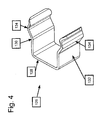
- FIG. 4 3 shows a schematic 3D illustration of a fastening clamp 126.
- the clamp is designed so that it can be passed through a recess 118 of the support frame element 114 and serves to establish a clamping connection between the support frame element 114 and the conveyor bar 102.
- the fastening clamp 126 has a bottom surface 128 , a left side surface 130, and a right side surface 132. The side surfaces are each formed equally and have a first vertically projecting from the bottom surface 128 surface. In the upper area, the opening of the fastening clip 126 widens first, before it in turn becomes narrower. This bulge 134 serves to receive the conveyor bar 102.
- FIG. 5 shows a schematic representation of a plan view of a conveyor bar 102.
- the conveyor bar 102 has two recesses 120 and 122.
- the recess 122 is preferably located on the task side of the flow shelf and serves for attachment by means of a positive connection with a tab on the support frame element.
- the recess 120 serves to receive a tab 116 of the support frame member 114 so that the conveyor bar 102 rests flat on the support surface of the support frame member and the tabs 116 do not belong to the support surface.
- FIG. 5 two ends of a conveyor bar are shown, wherein the one end has the recess 122 and at the other end no recess is shown.
- the end with the recess 122 is adapted to make a positive connection with a tab 116 of the support frame member 114.
- the end with the recess 122 is therefore intended to form the end of the conveyor bar on the task side of the flow shelf.
- the opposite end, in the in FIG. 5 No recess is shown, accordingly forms the end of the discharge side of the flow shelf. So it is not absolutely necessary that there is a recess in the conveyor bar on the removal side.
- FIG. 2 and 8th Other embodiments of a conveyor bar are shown with a recess at the end of the removal side.
- FIG. 6a shows a schematic representation of a conveyor bar 102, a support frame member 114 and a mounting bracket 126 in a side view.
- the support frame member 114 is angular.
- the mounting clamp 126 is performed by the recess 118 of the support frame member 114.
- the conveyor bar 102 is not yet in contact with the support frame member 114.
- the support frame member 114 further includes two tabs 116.
- FIG. 6b shows a schematic representation of a conveyor bar 102, a support frame member 114 and a mounting bracket 126 in a side view.
- the rear tab 116 on the task side 108 engages in a recess on the conveyor bar 102.
- the tab 116 forms with the recess in the conveyor bar 102 a positive connection.
- the mounting clamp 126 is in the FIG. 6b suspended in the recess 118.
- the conveyor bar 102 is not in contact with the support frame member 114 on the unloading side.
- the attachment of the conveyor bar 102 to the feed side 108 by means of the tab 116 and the recess on the conveyor bar 102 is done by holding the conveyor bar 102 at an angle, as in FIG of the FIG. 6b shown, and is pushed backwards until the tab 116 forms a positive connection with the recess.
- FIG. 6c shows a schematic representation of a conveyor bar 102, a support frame member 114 and a mounting bracket 126 in a side view.
- the conveyor bar 102 is still connected to the support frame member 114 by the tab 116 on the task side 108.
- the conveyor bar 102 is in FIG. 6c pressed down during assembly on the sampling side and pressed into the mounting clamp 126.
- FIG. 6d shows the arrangement FIG. 6c with a completely clamped in the mounting clamp 126 conveyor bar 102.
- the tab 116 directly behind the recess 118 engages in a recess in the conveyor bar 102 (in FIG. 6d not shown).
- the mounting clamp 126 connects with a clamping connection, the conveyor bar 102 with the support frame member 114 on the sampling side.
- the tab 116 forms a positive connection with a recess in the conveyor bar 102 (in FIG. 6d not shown).
- FIG. 7 shows a schematic view of the support frame member 114, the mounting clamp 126 and the conveyor bar 102 in cross section.
- the support frame member 114 is angular.
- the mounting clamp 126 engages through a recess of the support frame member 114 (in FIG FIG. 7 not shown) and provides a clamping connection of the conveyor bar 102 with the support frame member 114th ago.
- the conveyor bar 102 is pressed from above into the mounting clamp 126 and is clamped in the bulge 134 of the side surfaces 130 and 132 of the mounting clamp 126.
- FIG. 8a shows a schematic representation of a portion of a conveyor bar 102 having a recess 122.
- the recess 122 serves to receive a fastening element of the support frame member and forms a positive connection with the fastening element on the task side.
- the recess 122 is arranged at the end of the conveyor bar 102 and tapers. The widest point of the recess 122 is located at the end of the conveyor bar 102, so that the insertion of the fastener into the recess 122 is simplified.
- FIG. 8b shows a schematic representation of a portion of a conveyor bar 102 having a recess 124.
- the shape of the recess 124 results from a play of the shape of the recess 122 in FIG. 8a ,
- the recess 124 is preferably arranged on the removal side of the flow shelf.
- FIG. 8b has the conveyor bar in FIG. 8b at the end of the removal side a recess 124. This is advantageous since no waste is produced during the production of the conveyor strips, since the end at the removal side of a first conveyor bar connects directly to the end at the feed side of a second conveyor bar seamlessly at a conveyor strip endless profile. When cutting out the conveyor bars from the conveyor strip endless profile so no waste, which could not be used for a conveyor bar.
- FIG. 8c shows a schematic representation of a portion of a conveyor bar 102 with a recess 120.
- the shape of the recess 120 results from the shapes of the recesses 122 in FIG. 8a and 124 in FIG. 8b .
- the two forms of the recesses 122 and 124 must be brought together with their widest point in each case.
- the recess 120 thus has its widest point in the middle.
- the recess 120 is twice as long as the recesses 122 and 124.
- the shape of the recess 120 is obtained by mirroring the shape of the recess 122 on the mirror axis 135 and bringing the shape of the recess 122 into contact with the mirrored shape. Reflection of the shape of the recess 124 on the mirror axis 135 is also possible. In that case, the mirrored shape and the original shape must again be brought into contact with each other at their respectively widest point.
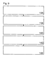
- FIG. 9 shows a block diagram of a method for mounting a conveyor bar according to the invention in an inventive flow shelf.
- the entire assembly is carried out in an already constructed shelf exclusively from the sampling side.
- a mounting clamp on the discharge side is performed by a recess of the support frame member and suspended 136th
- the conveyor bar is placed on the support frame element.
- the tab of the support frame element is inserted on the task side in the recess of the conveyor bar 142.
- the recess is tapered, since the tab can then be easily inserted.
- the conveyor bar When the tab of the support frame member is inserted into the recess of the conveyor bar, the conveyor bar is pressed from the sampling side down and clamped in the mounting clamp 144. Now the conveyor bar is clamped on the support surface of the support frame member.
- several mounting clamps can be used.
- Several tabs of the support frame element engage in recesses of the conveyor bar. A recess is formed in each case for receiving a tab. At the sampling side slipping out of the conveyor bar prevented by a withdrawal edge, which also prevents the falling out of cargo.
Landscapes
- Engineering & Computer Science (AREA)
- Mechanical Engineering (AREA)
- Warehouses Or Storage Devices (AREA)
Description
- Die Erfindung betrifft ein Durchlaufregal mit einem Stützrahmen zur Befestigung einer Förderleiste, ein Verfahren zur Herstellung einer Förderleiste und eines Stützrahmens für ein Durchlaufregal und ein Montageverfahren für ein Durchlaufregal mit einem Stützrahmen zur Befestigung von Förderleisten.
- Üblicherweise wird ein Durchlaufregal am Boden liegend fertig montiert und als ganzes Regal aufgestellt. Ein Durchlaufregal weist üblicherweise eine Aufgabeseite und eine Entnahmeseite auf. An der Entnahmeseite können die sich im Durchlaufregal befindenden Stückgüter entnommen werden. An der Aufgabeseite werden sie automatisch oder manuell in das Durchlaufregal nachgefüllt. Die Förderleisten des Durchlaufregals verlaufen von der Aufgabeseite hin zur Entnahmeseite mit einer negativen Steigung. Durch die Schwerkraft wird gewährleistet, dass die im Regal gelagerten Güter sich von der Aufgabeseite hin zur Entnahmeseite bewegen.
-
DE 9 003 104 U1 offenbart eine Förderleiste, die durch Laschen und Ausnehmungen auf dem Stützrahmen befestigt ist.
Der vorliegenden Erfindung liegt demgegenüber die Aufgabe zugrunde, ein Durchlaufregal zu schaffen, wobei die Förderleisten einfach hergestellt werden können. - Die der Erfindung zugrunde liegenden Aufgaben werden mit den Merkmalen der unabhängigen Patentansprüche gelöst. Ausführungsformen der Erfindung sind in den abhängigen Patentansprüchen gegeben.
- Wenn im nachfolgenden "an der Entnahmeseite" oder "auf der Entnahmeseite" erwähnt wird, meint dies einen Bereich zwischen der Mitte des Durchlaufregals und der Entnahmeseite. Wenn im nachfolgenden "an der Aufgabeseite" oder "auf der Aufgabeseite" erwähnt wird, meint dies einen Bereich zwischen der Mitte des Durchlaufregals und der Aufgabeseite.
- Erfindungsgemäß wird ein Durchlaufregal mit einem Stützrahmen zur Befestigung von Förderleisten geschaffen, die eine einfachere Anbringung der Förderleisten ermöglicht. Der Stützrahmen weist ein von einer Aufgabeseite zu einer Entnahmeseite verlaufendes Stützrahmenelement auf, wobei das Stützrahmenelement an der Aufgabeseite ein erstes Befestigungselement aufweist. Das erste Befestigungselement kann beispielsweise eine Lasche sein. Das erste Befestigungselement ist dabei zur Ausbildung einer formschlüssigen Verbindung mit einer der Förderleisten ausgebildet. Beispielsweise kann diese formschlüssige Verbindung durch ein Eingreifen der Lasche in eine Ausnehmung an der Förderleiste realisiert werden. Ein zweites Befestigungselement dient zur Bildung einer Klemmverbindung an der Entnahmeseite zwischen dem Stützrahmenelement und der Förderleiste.
- Dadurch, dass das erste Befestigungselement des Stützrahmenelements an der Aufgabeseite eine formschlüssige Verbindung mit einer der Förderleisten bildet, wird der Einbau der Förderleisten in das Durchlaufregal vereinfacht. Es ist möglich, die Förderleiste von einer Seite in das Durchlaufregal einzuschieben und mit dem Stützrahmenelement zu verbinden. Vorzugsweise erfolgt die Befestigung der Förderleiste am Stützrahmenelement an der Aufgabeseite durch eine Lasche am Stützrahmenelement, die in eine Ausnehmung an der Förderleiste eingreift. An der Entnahmeseite erfolgt die Befestigung der Förderleiste am Stützrahmenelement vorzugsweise durch einen Clip, der eine Klemmverbindung zwischen der Förderleiste und dem Stützrahmenelement herstellt. Die Förderleiste kann also von der Entnahmeseite aus montiert werden, in dem sie von der Entnahmeseite aus zur Aufgabeseite durchgeschoben wird, wo die Lasche des Stützrahmenelements in die Ausnehmung der Förderleiste greift. An der Entnahmeseite wird die Förderleiste dann mit Hilfe des Clips am Stützrahmenelement befestigt.
- Diese Art der Befestigung der Förderleiste am Stützrahmenelement ist vorteilhaft, da die Montage der Förderleisten in einem aufgestellten Regal von einer Seite erfolgen kann. Es wird so ermöglicht, die Förderleisten erst am Ende des Aufbaus des Durchlaufregals zu montieren. Dies ist vorteilhaft, da so andere Arbeiten - durch z.B. Mörtel - die Rollen nicht verschmutzen können. Auch ein Austausch der Förderleisten wird vereinfacht, da diese einfach von der Entnahmeseite aus herausgenommen werden können und durch neue Förderleisten ersetzt werden können. Im Rahmen des Aus- oder Einbaus einer Förderleiste ist es für den Monteur nicht notwendig, die Aufgabeseite des Durchlaufregals zu erreichen. Etwaige dort angebrachte automatische Nachfülleinrichtungen, können an der Aufgabeseite verbleiben, ohne dass sie die Montage der Förderleisten beinträchtigen. Auf ein Gerüst beim Anbringen oder Abmontieren der Förderleisten an der Aufgabeseite kann verzichtet werden.
- Auch wenn an der Aufgabeseite keine automatische Nachfülleinrichtung angebracht ist, sind Ausführungsformen der Erfindung vorteilhaft, da die Montage der Förderleisten alleine von der Entnahmeseite aus durchgeführt werden kann. Es wird also lediglich ein Monteur benötigt, der alle Förderleisten eines Durchlaufregals von einer Seite aus montieren kann. Es ist nicht nötig, dass der Monteur sich zur Aufgabeseite begeben muss, um die Förderleisten zu montieren.
- Nach Ausführungsformen der Erfindung ist das Stützrahmenelement winkelförmig ausgebildet. Dies ist vorteilhaft, da so eine höhere Stabilität gewährleistet wird.
- Nach Ausführungsformen der Erfindung dient das Stützrahmenelement als Auflage für eine Förderleiste. Die Förderleiste liegt also auf dem Stützrahmenelement auf.
- Nach Ausführungsformen der Erfindung weist die Förderleiste eine erste Ausnehmung an der Aufgabeseite auf. Dabei ist das erste Befestigungselement zum Eingriff in die erste Ausnehmung ausgebildet. Vorzugsweise ist das erste Befestigungselement eine Lasche am Stützrahmenelement und die erste Ausnehmung an der Förderleiste ist so ausgebildet, dass sie mit der Lasche eine formschlüssige Verbindung eingeht. Beispielsweise kann so die Förderleiste von der Entnahmeseite aus an dem Stützrahmenelement befestigt werden.
- Nach Ausführungsformen der Erfindung weist die erste Ausnehmung einen vorderen Bereich auf, der in Richtung der Aufgabeseite zur Entnahmeseite verjüngend ausgebildet ist. Das erste Befestigungselement ist als eine Lasche ausgebildet. Dies ist vorteilhaft, da die Lasche mit der ersten Ausnehmung eine formschlüssige Verbindung eingeht. Dadurch, dass die erste Ausnehmung von der Aufgabeseite zur Entnahmeseite hin verjüngend ausgebildet ist, wird das Einführen der Lasche in die Ausnehmung erleichtert.
- Nach Ausführungsformen der Erfindung weist das Stützrahmenelement eine zweite Ausnehmung an der Entnahmeseite auf, die zur Aufnahme eines zweiten Befestigungselements ausgebildet ist. Das zweite Befestigungselement kann beispielsweise eine Befestigungsklemme sein. Das zweite Befestigungselement wird nach Ausführungsformen der Erfindung durch die zweite Ausnehmung an der Entnahmeseite des Stützrahmenelements durchgeführt und dient zur Ausbildung einer Klemmverbindung mit der Förderleiste. Beispielsweise greift die Befestigungsklemme von unten durch das Stützrahmenelement und die Förderleiste wird von oben in die Befestigungsklemme eingeklemmt. Weitere Befestigungsklemmen können - z.B. bei Förderleisten ab einer Länge von 2m - zwischen der Aufgabe- und der Entnahmeseite angeordnet sein, um eine noch stabilere Befestigung der Förderleiste zu erreichen.
- Nach Ausführungsformen der Erfindung weist das Stützrahmenelement zumindest eine weitere Lasche auf, wobei die Laschen äquidistant angeordnet sind. Jede Lasche steht dabei von einer Auflagefläche des Stützrahmenelements ab. Die Auflagefläche ist die Fläche, auf der die an dem Stützrahmenelement befestigte Förderleiste aufliegt. Eine äquidistante Anordnung identischer Laschen an dem Stützrahmenelement hat den Vorteil einer einfacheren und kostengünstigeren Herstellung. Vorzugsweise werden die Stützrahmenelemente in Form eines Endlosprofils hergestellt. In dieses Stützrahmenelement-Endlosprofil werden nun beispielsweise mit Hilfe eines Stanzwerkzeuges die Laschen gestanzt. Bei einer äquidistanten Anordnung der identischen Laschen werden die Laschen beispielsweise von dem Stanzwerkzeug regelmäßig in das Stützrahmenelement-Endlosprofil gestanzt. Später können verschieden lange Stützrahmenelemente aus dem Stützrahmenelement-Endlosprofil hergestellt werden.
- Vorzugsweise weist die Förderleiste eine dritte Ausnehmung auf, in die in der Montageposition eine zweite Lasche des Stützrahmenelements ragt. Die dritte Ausnehmung hat eine Form, die sich aus der Form der ersten Ausnehmung und der gespiegelten Form der ersten Ausnehmung ergibt. Die dritte Ausnehmung in der Förderleiste ist vorteilhaft, da die zweite Lasche in sie hineinragt. Die dritte Ausnehmung ermöglicht es so, dass die Auflagefläche des Stützrahmenelements eben ist und die Förderleiste nicht auf der zweiten Lasche aufliegt. Die Form der dritten Ausnehmung ist vorteilhaft, da sich so die erste Ausnehmung und die dritte Ausnehmung durch das gleiche Werkzeug herstellen lassen. Dies kann beispielsweise ein Stanzwerkzeug sein. Dadurch, dass die dritte Ausnehmung sich aus der Form der ersten Ausnehmung und der gespiegelten Form der ersten Ausnehmung ergibt, lassen sich beide Ausnehmungen durch äquidistantes Stanzen der dritten Ausnehmung in ein Förderleisten-Endlosprofil herstellen. Hierfür wird das Förderleisten-Endlosprofil an der Stelle durchtrennt, an der die erste Ausnehmung angeordnet sein soll. Das Förderleisten-Endlosprofil wird in der Mitte einer dritten Ausnehmung durchtrennt, wodurch sich eine erste Ausnehmung ergibt. Das Ende dieser so hergestellten Förderleiste mit der ersten Ausnehmung stellt vorzugsweise das Ende der Förderleiste an der Aufgabeseite dar.
- Nach Ausführungsformen der Erfindung ist eine begehbare Bühne an der Entnahmeseite des Durchlaufregals angeordnet. Eine begehbare Bühne dient üblicherweise dazu, es dem Benutzer zu ermöglichen, Güter auch aus höheren Lagerorten des Durchlaufregals zu entnehmen. Eine solche Bühne ist vorteilhaft für Ausführungsformen der Erfindung, da sie auch für die Montage der Förderleisten am Durchlaufregal genutzt werden kann. So muss kein Gerüst auf der Entnahmeseite zur Montage der Förderleisten aufgebaut werden.
- Nach Ausführungsformen der Erfindung ist an der Aufgabeseite des Durchlaufregals eine automatische Zuführung angeordnet. Eine automatische Zuführung ist vorteilhaft, da sie automatisch die Güter in das Durchlaufregal nachführt. Dadurch, dass nach Ausführungsformen der Erfindung die Förderleisten lediglich von der Entnahmeseite aus montiert werden können und ein Zugang zu der Aufgabeseite nicht benötigt wird, wird die automatische Zuführung durch den Einbau oder den Ersatz der Förderleisten nicht beeinträchtigt.
- Nach Ausführungsformen der Erfindung wurden die Ausnehmungen und Befestigungselemente der Förderleisten und Stützrahmenelemente ausgestanzt. Dies ist vorteilhaft, da es eine einfache und kostengünstige Herstellung der Stützrahmenelemente und Förderleisten ermöglicht. Vorzugsweise werden Förderleisten und Stüfizrahmenelemente in Form von Endlosprofilen hergestellt, in die dann die Ausnehmungen und Befestigungselemente gestanzt werden.
- Nach Ausführungsformen der Erfindung sind die erste Ausnehmung und das erste Befestigungselement in einem Bereich von 5 bis 40 mm vor dem Ende des Durchlaufregals an der Aufgabeseite angeordnet.
- Nach Ausführungsformen der Erfindung sind die zweite Ausnehmung und das zweite Befestigungselement in einem Bereich von 5 bis 300 mm vor dem Ende des Durchlaufregals an der Entnahmeseite angeordnet.
- Nach Ausführungsformen der Erfindung ist zwischen der Entnahmeseite und der Aufgabeseite zumindest eine weitere Befestigungsklemme zur Befestigung der Förderleiste am Stützrahmenelement angeordnet. Die Befestigung der Förderleiste mit Hilfe der Befestigungsklemme am Stützrahmenelement erfolgt hier nach dem gleichen Prinzip wie an der Entnahmeseite. Die Befestigungsklemme wird durch eine Ausnehmung in dem Stützrahmenelement durchgesteckt und die Förderleiste wird in sie hinein geklemmt, sodass eine Klemmverbindung entsteht.
- Nach Ausführungsformen der Erfindung ist die Förderleiste als Rollenleiste ausgebildet. Vorzugsweise besteht die Rollenleiste aus mehreren quer zur Förderrichtung angeordneten Rollen, die drehbar in einem Rollenleistenprofil gelagert sind. Stückgut kann von der Aufgabe- zur Entnahmeseite über die so angeordneten Rollen transportiert werden.
- Nach Ausführungsformen der Erfindung ist die Förderleiste eine Rutschschiene. Vorzugsweise ist die Rutschschiene mit einem Kunststoff mit einem niedrigen Reibungskoeffizienten beschichtet, was ein Rutschen von Stückgut leichter möglich macht. Ferner kann beispielsweise der Reibungskoeffizient durch Gleitmittel verringert werden. Beispielsweise wird die Rutschschiene mit einer Steigung von 10-30% montiert, obwohl auch flachere oder steilere Steigungen realisiert werden können.
- Nach Ausführungsformen der Erfindung weist die Förderleiste ein Förderband auf. Beispielsweise ist zumindest ein Förderband so angeordnet, dass es zum Transport von Stückgut von der Aufgabe- zur Entnahmeseite ausgebildet ist. Es ist dabei nicht notwendig aber möglich, dass das Förderband die gesamte Breite der Förderleiste einnimmt. Das Förderband kann sich aber auch nur über einen Teil der Förderleiste erstrecken. Beispielsweise weist das Förderband eine Breite von 1-10cm auf, obwohl auch kleinere oder größere Breiten realisiert werden können.
- Nach Ausführungsformen der Erfindung ist die Förderleiste so ausgebildet, dass Zahnräder das Stückgut von der Aufgabe- zur Entnahmeseite transportieren. Hierzu ist eine Vielzahl von Zahnrädern an der Förderleiste angeordnet, die das Stückgut transportieren, indem sie mit ihren Zähnen von unten in das Stückgut greifen. Dadurch, dass die Zahnräder drehbar gelagert sind, kann bei einer Drehung der Zahnräder das Stückgut so von der Aufgabe- zur Entnahmeseite transportiert werden.
- Eine Vielzahl weiterer Ausbildungsmöglichkeiten der Förderleiste ist denkbar. Als Förderleiste kann jegliches Mittel verstanden werden, das dazu ausgebildet ist, Stückgut von der Aufgabe- zur Entnahmeseite zu transportieren.
- Eine Förderbahn für Stückgut kann aus einer einzelnen Förderleiste gebildet werden. Dies ist vorzugsweise dann der Fall, wenn die Breite des zu transportierenden Stückguts mit der Breite der Förderleiste übereinstimmt oder wenn die Breite des zu transportierenden Stückguts kleiner ist als die Breite der Förderleiste.
- Eine Förderbahn für Stückgut kann aber auch aus zwei oder mehreren Förderleisten gebildet werden. Dies ist vorzugsweise dann der Fall, wenn die Breite des zu transportierenden Stückguts die Breite einer Förderleiste übersteigt
- In einem weiteren Aspekt, betrifft die Erfindung ein Verfahren zur Herstellung einer Förderleiste und eines Stützrahmens für ein Durchlaufregal. Das Verfahren umfasst das Ausstanzen von äquidistanten dritten Ausnehmungen in ein Förderleisten-Endlosprofil, das Austanzen von ebenso äquidistanten zweiten Ausnehmungen und ersten Befestigungselementen in ein Stützrahmenelement-Endlosprofil. Hierbei sind vorzugsweise die Distanzen zwischen den dritten Ausnehmungen gleich den Distanzen zwischen den ersten Befestigungselementen. Dies ist vorteilhaft, da so jedes erste Befestigungselement durch eine dritte Ausnehmung hindurchgeführt werden kann. Ferner umfasst das Verfahren das Zuschneiden der Endlosprofile auf die gewünschte Länge. Dabei wird eine dritte Ausnehmung des Förderleisten-Endlosprofils an der Aufgabeseite beim Zuschneiden in der Mitte geteilt, sodass eine erste Ausnehmung entsteht. Vorzugsweise stellt dieses Ende der Förderleiste das Ende an der Aufgabeseite dar.
- In einem weiteren Aspekt betrifft die Erfindung ein Montageverfahren für ein Durchlaufregal. Dabei umfasst das Montageverfahren die Montage des Stützrahmens mit Stützrahmenelementen, die Montage einer begehbare Bühne an der Entnahmeseite, das Auflegen zumindest einer Förderleiste auf ein Stützrahmenelement, das Durchschieben der Förderleiste auf dem Stützrahmenelement bis die erste Ausnehmung der Förderleiste eine formschlüssige Verbindung mit dem ersten Befestigungselement des Stützrahmenelements bildet und das Einklemmen der Förderleiste in das zweite Befestigungselement. Die Montage der Förderleiste erfolgt hierbei vorzugsweise ausschließlich über die Entnahmeseite. Durch die begehbare Bühne ist das Durchlaufregal an jeder Stelle von der Entnahmeseite aus leicht zugänglich, was die Montage der Förderleisten vereinfacht. Dadurch, dass die Förderleisten lediglich jeweils auf ein Stützrahmenelement aufgelegt werden und nach hinten zur Aufgabeseite durchgeschoben werden, wo das erste Befestigungselement mit der erste Aufnehmung der Förderleiste eine formschlüssige Verbindung eingeht, ist ein Zugang von der Aufgabeseite aus nicht nötig. Etwaige automatische Zuführungen an der Aufgabeseite müssen nicht verändert werden, wenn die Förderleisten installiert oder ersetzt werden sollen. Das Einklemmen der Förderleiste in das zweite Befestigungselement gestaltet die Installation und das Ersetzen der Förderleisten einfach und kostengünstig.
- Im Weiteren werden Ausführungsformen der Erfindung mit Bezugnahme auf die Zeichnungen näher erläutert. Es zeigen:
- Figur 1
- eine schematische Darstellung eines erfindungsgemäßen Durchlaufre- gals,
- Figur 2a
- eine schematische Darstellung der Draufsicht auf ein erfindungsgemä- ßes Stützrahmenelement,
- Figur 2b
- eine schematische Darstellung der Draufsicht auf eine erfindungsge- mäße Förderleiste,
- Figur 3
- eine schematische perspektivische 3D-Darstellung eines erfindungs- gemäßen ersten Befestigungselements und einer zweiten Ausneh- mung an einem erfindungsgemäßen Stützrahmenelement,
- Figur 4
- eine schematische Darstellung einer erfindungsgemäßen Befesti- gungsklemme,
- Figur 5
- eine schematische Darstellung einer ersten und dritten erfindungsge- mäßen Ausnehmung in Draufsicht auf eine erfindungsgemäße Förder- leiste,
- Figur 6a
- eine schematische Darstellung der Seitenansicht einer erfindungsge- mäßen Förderleiste, einer erfindungsgemäßen Befestigungsklemme und eines erfindungsgemäßen Stützrahmenelements,
- Figur 6b
- eine schematische Darstellung der Seitenansicht einer erfindungsge- mäßen Förderleiste, einer erfindungsgemäßen Befestigungsklemme und eines erfindungsgemäßen Stützrahmenelements,
- Figur 6c
- eine schematische Darstellung der Seitenansicht einer erfindungsge- mäßen Förderleisten, einer erfindungsgemäßen Befestigungsklemme und eines erfindungsgemäßen Stützrahmenelements,
- Figur 6d
- eine schematische Darstellung der Seitenansicht einer erfindungsge- mäßen Förderleiste, einer erfindungsgemäßen Befestigungsklemme und eines erfindungsgemäßen Stützrahmenelements,
- Figur 7
- eine schematische Darstellung der Vorderansicht einer erfindungsge- mäßen Förderleiste, befestigt mit einer erfindungsgemäßen Befesti- gungsklemme an einem erfindungsgemäßen Stützrahmenelement,
- Figur 8a
- eine schematische Darstellung eines Teils einer Förderleiste mit einer Ausnehmung,
- Figur 8b
- eine schematische Darstellung eines Teils einer Förderleiste mit einer Ausnehmung,
- Figur 8c
- eine schematische Darstellung eines Teils einer Förderleiste mit einer Ausnehmung, und
- Figur 9
- ein Blockdiagramm eines Verfahrens zur Montage einer erfindungs- gemäßen Förderleiste in ein erfindungsgemäßes Durchlaufregal.
- Elemente der nachfolgenden Figuren, die einander entsprechen, sind mit denselben Bezugszeichen gekennzeichnet.
-
Figur 1 zeigt eine schematische Darstellung eines Durchlaufregals 100 mit mehreren erfindungsgemäßen Förderleisten 102 und mehreren erfindungsgemäßen Stützrahmen 104. Das Durchlaufregal 100 weist eine Entnahmeseite 106 und eine Aufgabeseite 108 auf. Auf der Entnahmeseite 106 befindet sich eine Bühne 110. An der Aufgabeseite 108 befindet sich eine automatische Zuführung 112. Ferner weist das Durchlaufregal 100 mehrere Stützrahmenelemente 114 auf. An der Aufgabeseite befindet sich eine automatische Zuführung 112 für die automatische Nachfüllung des Durchlaufregals 100. - Die Montage der Förderleisten 102 kann komplett von der Entnahmeseite 106 aus durchgeführt werden. Für die höheren Förderleisten kann dies von der Bühne 110 aus durchgeführt werden. Ein Zugriff auf den Stützrahmen 104 von der Aufgabeseite 108 aus, ist nicht erforderlich. Dadurch bleibt die automatische Zuführung 112 von einer Montage oder Erneuerung der Förderleisten 102 unberührt. Die Person 115 auf der Bühne 110 montiert eine Förderleiste 102 auf einem Stützrahmenelement 114. Die Förderleiste 102 wird hierfür zunächst bis hinten zur Aufgabeseite 108 durchgeschoben, wo beispielsweise eine Lasche des Stützrahmenelements 114 mit einer Ausnehmung in der Förderleiste 102 eine formschlüssige Verbindung herstellt. An der Entnahmeseite 106 wird die Förderleiste 102 mit Hilfe einer Klemmverbindung am Stützrahmenelement 114 befestigt.
- An der Entnahmeseite 106 ist am Stützrahmen 104 eine Entnahmekante 117 angeordnet, die verhindert, dass Stückgüter aus dem Durchlaufregal herausfallen. Ferner wird durch die Entnahmekante 117 verhindert, dass die Förderleiste 102 nach vorne zur Entnahmeseite 106 hin von dem Stützrahmenelement 114 herunterrutscht. Hinten an der Aufgabeseite 108 ist die Förderleiste 102 also beispielsweise mit einer Lasche an dem Stützrahmenelement 114 und einer Ausnehmung in der Förderleiste 102 befestigt und vorne an der Entnahmeseite 106 wird sie durch die Entnahmekante 117 am Herausrutschen gehindert. Zwischen diesen beiden Befestigungen wird mit Hilfe eines Befestigungselements eine Klemmverbindung zwischen Förderleiste 102 und Stützrahmenelement 114 hergestellt.
-
Figur 2a zeigt eine schematische Darstellung der Draufsicht auf ein erfindungsgemäßes Stützrahmenelement 114. An dem Stützrahmenelement sind Laschen 116 und Ausnehmungen 118 angeordnet. Durch die Unterbrechung in der Förderleiste 102 wird dargestellt, dass ein Abschnitt der Förderleiste 102 nicht gezeigt wird. -
Figur 2b zeigt eine schematische Darstellung einer Draufsicht auf eine erfindungsgemäße Förderleiste 102. An der Förderleiste 102 sind Ausnehmungen 120, 122 und 124 angeordnet. Die Ausnehmungen 120, 122 und 124 sind jeweils ausgebildet, um eine Lasche 116 eines Stützrahmenelements 114 aufzunehmen. Die Ausnehmungen 122 und 124 befinden sich jeweils am Ende der Förderleiste 102. Sie können zur Befestigung der Förderleiste 102 an der Aufgabeseite des Durchlaufregals an dem Stützrahmenelement 114 dienen. Durch die Unterbrechung in der Förderleiste 102 wird dargestellt, dass ein Abschnitt der Förderleiste 102 nicht gezeigt wird. - Dadurch, dass sich an beiden Enden der Förderleiste 102 Ausnehmungen 122 und 124 befinden, entsteht bei der Herstellung einer solchen Förderleiste aus einem Förderleisten-Endlosprofil keinerlei Verschnitt, da das Ende mit der Ausnehmung 124 sich im Förderleisten-Endlosprofil direkt nahtlos an das Ende mit der Ausnehmung 122 anschließt.
-
Figur 3 zeigt eine schematische perspektivische 3D-Darstellung eines Ausschnitts eines erfindungsgemäßen Stützrahmenelements 114. An dem Stützrahmenelement 114 sind eine Lasche 116 und eine Ausnehmung 118 angeordnet. Die Lasche 116 ist so ausgebildet, dass sie an der Aufgabeseite 108 eines Durchlaufregals 100 eine formschlüssige Verbindung mit einer Ausnehmung 122 an der Förderleiste eingehen kann. Die Ausnehmung 118 ist so ausgebildet, dass durch sie ein Befestigungselement 126 hindurch geführt werden kann, mit dem eine Klemmverbindung des Stützrahmenelements 114 mit einer Förderleiste hergestellt werden kann. Vorzugsweise werden die Lasche 116 und die Ausnehmung 118 immer paarweise an dem Stützrahmenelement 114 angeordnet, da sie vorzugsweise mit einem einzigen Ausstanzwerkzeug hergestellt werden. Dies ermöglicht eine einfache und kostengünstige Herstellung der Stützrahmenelemente 114. -
Figur 4 zeigt eine schematische 3D-Darstellung einer Befestigungsklemme 126. Die Klemme ist so ausgebildet, dass sie durch eine Ausnehmung 118 des Stützrahmenelements 114 durchgeführt werden kann und dient zur Herstellung einer Klemmverbindung zwischen dem Stützrahmenelement 114 und der Förderleiste 102. Die Befestigungsklemme 126 weist eine Bodenfläche 128, eine linke Seitenfläche 130, sowie eine rechte Seitenfläche 132 auf. Die Seitenflächen sind jeweils gleichermaßen ausgebildet und weisen eine zunächst senkrecht von der Bodenfläche 128 abstehende Fläche auf. Im oberen Bereich verbreitert sich die Öffnung der Befestigungsklemme 126 zunächst, bevor sie im Anschluss wiederum schmaler wird. Diese Auswölbung 134 dient zur Aufnahme der Förderleiste 102. -
Figur 5 zeigt eine schematische Darstellung einer Draufsicht auf eine Förderleiste 102. Es sind verschiedene Teilstücke der Förderleiste 102 dargestellt, was durch die gezackte Unterbrechung der Förderleiste 102 dargestellt wird. Die Förderleiste 102 weist zwei Ausnehmungen 120 und 122 auf. Die Ausnehmung 122 befindet sich vorzugsweise an der Aufgabeseite des Durchlaufregals und dient zur Befestigung mit Hilfe einer formschlüssigen Verbindung mit einer Lasche an dem Stützrahmenelement. Die Ausnehmung 120 dient zur Aufnahme einer Lasche 116 des Stützrahmenelements 114, damit die Förderleiste 102 flach auf der Auflagefläche des Stützrahmenelements aufliegt und die Laschen 116 nicht zur Auflagefläche gehören. - In
Figur 5 werden zwei Enden einer Förderleiste dargestellt, wobei das eine Ende die Ausnehmung 122 aufweist und am anderen Ende keine Ausnehmung dargestellt ist. Das Ende mit der Ausnehmung 122 ist dafür ausgebildet mit einer Lasche 116 des Stützrahmenelements 114 eine formschlüssige Verbindung herzustellen. Das Ende mit der Ausnehmung 122 ist daher dazu vorgesehen, das Ende der Förderleiste an der Aufgabeseite des Durchlaufregals zu bilden. Das gegenüberliegende Ende, in dem inFigur 5 keine Ausnehmung dargestellt ist, bildet dementsprechend das Ende an der Entnahmeseite des Durchlaufregals. Es ist also nicht zwingend notwendig, dass sich an der Entnahmeseite eine Ausnehmung in der Förderleiste befindet. In denFiguren 2 und8 werden andere Ausführungsformen einer Förderleiste mit einer Ausnehmung am Ende an der Entnahmeseite dargestellt. -
Figur 6a zeigt eine schematische Darstellung einer Förderleiste 102, eines Stützrahmenelements 114 und einer Befestigungsklemme 126 in seitlicher Ansicht. Das Stützrahmenelement 114 ist winkelförmig ausgebildet. Die Befestigungsklemme 126 wird durch die Ausnehmung 118 des Stützrahmenelements 114 durchgeführt. Die Förderleiste 102 befindet sich noch nicht in Kontakt mit dem Stützrahmenelement 114. Das Stützrahmenelement 114 weist ferner zwei Laschen 116 auf. -
Figur 6b zeigt eine schematische Darstellung einer Förderleiste 102, eines Stützrahmenelements 114 und einer Befestigungsklemme 126 in seitlicher Ansicht. Die hintere Lasche 116 an der Aufgabeseite 108 greift in eine Ausnehmung an der Förderleiste 102. Die Lasche 116 bildet mit der Ausnehmung in der Förderleiste 102 eine formschlüssige Verbindung. Durch die Unterbrechung in derFigur 6b wird deutlich gemacht, dass hier ein Teil der Förderleiste 102 und des Stützrahmenelements 114 nicht dargestellt werden. Die Befestigungsklemme 126 ist in derFigur 6b in die Ausnehmung 118 eingehängt. Die Förderleiste 102 befindet sich an der Entnahmeseite nicht in Kontakt mit dem Stützrahmenelement 114. Die Befestigung der Förderleiste 102 an der Aufgabeseite 108 mit Hilfe der Lasche 116 und der Ausnehmung an der Förderleiste 102 geschieht dadurch, dass die Förderleiste 102 schräg gehalten wird, wie in derFigur 6b dargestellt, und nach hinten durchgeschoben wird, bis die Lasche 116 eine formschlüssige Verbindung mit der Ausnehmung bildet. -
Figur 6c zeigt eine schematische Darstellung einer Förderleiste 102, eines Stützrahmenelements 114 und einer Befestigungsklemme 126 in seitlicher Ansicht. Die Förderleiste 102 ist immer noch durch die Lasche 116 an der Aufgabeseite 108 mit dem Stützrahmenelement 114 verbunden. Die Förderleiste 102 wird inFigur 6c bei der Montage an der Entnahmeseite hinuntergedrückt und in die Befestigungsklemme 126 hineingedrückt. -
Figur 6d zeigt die Anordnung ausFigur 6c mit einer vollständig in die Befestigungsklemme 126 eingeklemmten Förderleiste 102. Die Lasche 116 direkt hinter der Ausnehmung 118 greift in eine Ausnehmung in der Förderleiste 102 (inFigur 6d nicht dargestellt). Die Befestigungsklemme 126 verbindet mit einer Klemmverbindung die Förderleiste 102 mit dem Stützrahmenelement 114 an der Entnahmeseite. An der Aufgabeseite 108 bildet die Lasche 116 eine formschlüssige Verbindung mit einer Ausnehmung in der Förderleiste 102 (inFigur 6d nicht dargestellt). -
Figur 7 zeigt eine schematische Ansicht des Stützrahmenelements 114, der Befestigungsklemme 126 und der Förderleiste 102 im Querschnitt. Das Stützrahmenelement 114 ist winkelförmig ausgebildet. Die Befestigungsklemme 126 greift durch eine Ausnehmung des Stützrahmenelements 114 (inFigur 7 nicht dargestellt) und stellt eine Klemmverbindung der Förderleiste 102 mit dem Stützrahmenelement 114 her. Die Förderleiste 102 wird von oben in die Befestigungsklemme 126 hineingedrückt und wird in der Ausbeulung 134 der Seitenflächen 130 und 132 der Befestigungsklemme 126 eingeklemmt. -
Figur 8a zeigt eine schematische Darstellung eines Teils einer Förderleiste 102 mit einer Ausnehmung 122. Die Ausnehmung 122 dient zur Aufnahme eines Befestigungselements des Stützrahmenelements und bildet an der Aufgabeseite eine formschlüssige Verbindung mit dem Befestigungselement. Die Ausnehmung 122 ist am Ende der Förderleiste 102 angeordnet und verjüngt sich. Die breiteste Stelle der Ausnehmung 122 befindet sich am Ende der Förderleiste 102, sodass das Einführen des Befestigungselements in die Ausnehmung 122 vereinfacht wird. -
Figur 8b zeigt eine schematische Darstellung eines Teils einer Förderleiste 102 mit einer Ausnehmung 124. Die Form der Ausnehmung 124 ergibt sich aus einer Spielung der Form der Ausnehmung 122 inFigur 8a . Die Ausnehmung 124 ist vorzugsweise an der Entnahmeseite des Durchlaufregals angeordnet. Im Gegensatz zuFigur 5 weist also die Förderleiste inFigur 8b am Ende an der Entnahmeseite eine Ausnehmung 124 auf. Dies ist vorteilhaft, da so keinerlei Verschnitt bei der Herstellung der Förderleisten entsteht, da bei einem Förderleisten-Endlosprofil das Ende an der Entnahmeseite einer ersten Förderleiste sich direkt an das Ende an der Aufgabeseite einer zweiten Förderleiste nahtlos anschließt. Beim Herausschneiden der Förderleisten aus dem Förderleisten-Endlosprofil entsteht also kein Verschnitt, der nicht für eine Förderleiste genutzt werden könnte. -
Figur 8c zeigt eine schematische Darstellung eines Teils einer Förderleiste 102 mit einer Ausnehmung 120. Die Form der Ausnehmung 120 ergibt sich aus den Formen der Ausnehmungen 122 inFigur 8a und 124 inFigur 8b . Um die Form der Ausnehmung 120 zu erhalten, müssen die beiden Formen der Ausnehmungen 122 und 124 mit ihrer jeweils breitesten Stelle aneinandergeführt werden. Die Ausnehmung 120 hat also ihre breiteste Stelle in der Mitte. Die Ausnehmung 120 ist doppelt so lang wie die Ausnehmungen 122 und 124. - Mit anderen Worten erhält man die Form der Ausnehmung 120, indem man die Form der Ausnehmung 122 an der Spiegelachse 135 spiegelt und die Form der Ausnehmung 122 mit der gespiegelten Form in Berührung bringt. Eine Spiegelung der Form der Ausnehmung 124 an der Spiegelachse 135 ist ebenfalls möglich. In dem Fall müssen wieder die gespiegelte Form und die ursprüngliche Form an ihrer jeweils breitesten Stelle miteinander in Berührung gebracht werden.
-
Figur 9 zeigt ein Blockdiagramm eines Verfahrens zur Montage einer erfindungsgemäßen Förderleiste in ein erfindungsgemäßes Durchlaufregal. Die gesamte Montage wird bei einem bereits aufgebauten Regal ausschließlich von der Entnahmeseite aus durchgeführt. Zunächst wird eine Befestigungsklemme an der Entnahmeseite durch eine Ausnehmung des Stützrahmenelements durchgeführt und eingehängt 136. - Im nächsten Schritt 138 wird die Förderleiste auf das Stützrahmenelement aufgelegt.
- Das Durchschieben der Förderleiste auf dem Stützrahmenelement bis zur Aufgabeseite erfolgt in Schritt 140.
- Wenn die Förderleiste bis zur Aufgabeseite durchgeschoben wurde, wird die Lasche des Stützrahmenelements an der Aufgabeseite in die Ausnehmung der Förderleiste eingeführt 142. Hierbei ist es hilfreich, wenn die Ausnehmung verjüngend ausgebildet ist, da die Lasche dann einfacher eingeführt werden kann.
- Wenn die Lasche des Stützrahmenelements in die Ausnehmung der Förderleiste eingeführt ist, wird die Förderleiste von der Entnahmeseite aus nach unten gedrückt und in die Befestigungsklemme eingeklemmt 144. Nun liegt die Förderleiste festgeklemmt auf der Auflagefläche des Stützrahmenelements. Gegebenenfalls können bei langen Förderleisten - z.B. ab 2m Länge - auch mehrere Befestigungsklemmen verwendet werden. Mehrere Laschen des Stützrahmenelements greifen in Ausnehmungen der Förderleiste. Eine Ausnehmung ist jeweils für die Aufnahme einer Lasche ausgebildet. An der Entnahmeseite wird ein Herausrutschen der Förderleiste durch eine Entnahmekante verhindert, die auch das Herausfallen von Stückgütern verhindert.
-
- 100
- Durchlaufregal
- 102
- Förderleiste
- 104
- Stützrahmen
- 106
- Entnahmeseite
- 108
- Aufgabeseite
- 110
- Bühne
- 112
- automatische Zuführung
- 114
- Stützrahmenelement
- 115
- Person
- 116
- Lasche
- 117
- Entnahmekante
- 118
- Ausnehmung
- 120
- Ausnehmung
- 122
- Ausnehmung
- 124
- Ausnehmung
- 126
- Befestigungsklemme
- 128
- Bodenfläche
- 130
- Seitenfläche
- 132
- Seitenfläche
- 134
- Auswölbung
- 135
- Spiegelachse
- 136
- Einhängen der Befestigungsklemme
- 138
- Auflegen der Förderleiste
- 140
- Durchschieben der Förderleiste
- 142
- Einführen der Lasche in Ausnehmung
- 144
- Einklemmen der Förderleiste
Claims (15)
- Durchlaufregal (100) mit einem Stützrahmen (104) zur Befestigung von Förderleisten (102), wobei der Stützrahmen ein von einer Aufgabeseite (108) zu einer Entnahmeseite (106) verlaufendes Stützrahmenelement (114) aufweist, wobei das Stützrahmenelement an der Aufgabeseite (108) ein erstes Befestigungselement (116) aufweist, wobei das erste Befestigungselement (116) zur Ausbildung einer formschlüssigen Verbindung mit einer der Förderleisten (102) ausgebildet ist, und mit einem zweiten Befestigungselement (126) zur Ausbildung einer Klemmverbindung an der Entnahmeseite (106) zwischen dem Stützrahmenelement (114) und der Förderleiste (102), wobei die Fördeneiste (102) eine erste Ausnehmung (122) an der Aufgabeseite (108) aufweist und das erste Befestigungselement (116) eine erste Lasche ist und zum Eingriff in die erste Ausnehmung (122) ausgebildet ist, wobei das Stützrahmenelement (114) zumindest eine zweite Lasche aufweist, wobei das Stützrahmenelement (114) zumindest eine zweite Ausnehmung (118) an der Entnahmeseite (106) zur Aufnahme zumindest der zumindest einen zweiten Lasche aufweist, wobei- die Laschen äquidistant angeordnet sind;- jede Lasche von einer Auflagefläche des Stützrahmenelements (114) absteht;- zumindest eine dritte Ausnehmung (120) in der Förderleiste (102) angeordnet ist, wobei in Montageposition die zweite Lasche in die dritte Ausnehmung (120) ragt,- die dritte Ausnehmung (120) eine Form hat, die sich aus der Form der ersten Ausnehmung (122) und der gespiegelten Form der ersten Ausnehmung (122) ergibt.
- Durchlaufregal nach Anspruch 1, wobei das Stützrahmenelement (114) winkelförmig ausgebildet ist.
- Durchlaufregal nach einem der vorhergehenden Ansprüche, wobei die erste Ausnehmung (122) einen vorderen Bereich aufweist, der in Richtung von der Aufgabeseite (108) zur Entnahmeseite (106) verjüngend ausgebildet ist, und das erste Befestigungselement (116) als eine Lasche ausgebildet ist.
- Durchlaufregal nach Anspruch 3, wobei das zweite Befestigungselement (126) eine Befestigungsklemme ist.
- Durchlaufregal nach einem der vorhergehenden Ansprüche, wobei an der Entnahmeseite (106) eine begehbare Bühne (110) angeordnet ist.
- Durchlaufregal nach einem der vorhergehenden Ansprüche, wobei eine automatische Zuführung (112) an der Aufgabeseite (108) angeordnet ist.
- Durchlaufregal nach einem der vorhergehenden Ansprüche, wobei das Durchlaufregal (100) für eine Handbeschickung ausgebildet ist.
- Durchlaufregal nach einem der vorhergehenden Ansprüche, wobei die Ausnehmungen (118,120,121) und Befestigungselemente (116,126) der Förderleisten (102) und Stützrahmenelemente (114) ausgestanzt wurden.
- Durchlaufregal nach einem der vorhergehenden Ansprüche, wobei die erste Ausnehmung (122) und das erste Befestigungselement (116) in einem Bereich von 5 bis 40mm vor dem Ende des Durchlaufregals (100) an der Aufgabeseite (108) angeordnet sind.
- Durchlaufregal nach einem der vorhergehenden Ansprüche, wobei die zweite Ausnehmung (118) und das zweite Befestigungselement (126) in einem Bereich von 5 bis 300mm vor dem Ende des Durchlaufregals (100) an der Entnahmeseite (106) angeordnet sind.
- Durchlaufregal nach einem der vorhergehenden Ansprüche, wobei zwischen Entnahmeseite (106) und Aufgabeseite (108) zumindest eine weitere Befestigungsklemme zur Befestigung der Förderleiste (102) am Stützrahmenelement (114) angeordnet ist.
- Durchlaufregal nach einem der vorherigen Ansprüche, wobei die Förderleiste (102) eine Rollenleiste ist.
- Durchlaufregal nach einem der vorhergehenden Ansprüche, wobei die Förderleiste (102) eine Rutschschiene ist.
- Durchlaufregal nach einem der vorhergehenden Anspruche, wobei die Förderleiste (102) ein Förderband und/oder Zahnräder aufweist.
- Verfahren zur Herstellung einer Förderleiste (102) und eines Stützrahmens (114) für ein Durchlaufregal (100) nach einem der Ansprüche 1-14, wobei das Verfahren die folgenden Schritte umfasst:- Ausstanzen von äquidistanten dritten Ausnehmungen (120) in ein Förderleistenendlosprofil;- Ausstanzen von ebenso äquidistanten zweiten Ausnehmungen (118) und ersten Befestigungselementen (116) in ein Stützrahmenelementendlosprofil; und- Zuschneiden der Endlosprofile auf die gewünschte Länge, wobei eine dritte Ausnehmung (120) des Förderleistenendlosprofils an der Aufgabeseite (108) beim Zuschneiden in der Mitte geteilt wird, sodass eine erste Ausnehmung (122) entsteht.
Priority Applications (1)
| Application Number | Priority Date | Filing Date | Title |
|---|---|---|---|
| PL10166884T PL2275362T3 (pl) | 2009-07-17 | 2010-06-22 | Regał przepływowy z ramą podporową do mocowania listwy transportowej |
Applications Claiming Priority (1)
| Application Number | Priority Date | Filing Date | Title |
|---|---|---|---|
| DE102009027795.1A DE102009027795B4 (de) | 2009-07-17 | 2009-07-17 | Durchlaufregal mit einem Stützrahmen zur Befestigung einer Förderleiste |
Publications (3)
| Publication Number | Publication Date |
|---|---|
| EP2275362A2 EP2275362A2 (de) | 2011-01-19 |
| EP2275362A3 EP2275362A3 (de) | 2012-02-22 |
| EP2275362B1 true EP2275362B1 (de) | 2012-09-12 |
Family
ID=42739590
Family Applications (1)
| Application Number | Title | Priority Date | Filing Date |
|---|---|---|---|
| EP10166884A Not-in-force EP2275362B1 (de) | 2009-07-17 | 2010-06-22 | Durchlaufregal mit einem Stützrahmen zur Befestigung einer Föderleiste |
Country Status (5)
| Country | Link |
|---|---|
| EP (1) | EP2275362B1 (de) |
| DE (1) | DE102009027795B4 (de) |
| DK (1) | DK2275362T3 (de) |
| ES (1) | ES2391621T3 (de) |
| PL (1) | PL2275362T3 (de) |
Families Citing this family (2)
| Publication number | Priority date | Publication date | Assignee | Title |
|---|---|---|---|---|
| AT509295B1 (de) * | 2010-01-15 | 2012-12-15 | Salomon Automation Gmbh | Vorrichtung und verfahren zur kommissionierung von artikeln |
| US12384626B2 (en) * | 2022-02-17 | 2025-08-12 | Frazier Industrial Company | Pallet storage and flow system and method |
Family Cites Families (4)
| Publication number | Priority date | Publication date | Assignee | Title |
|---|---|---|---|---|
| DE9003104U1 (de) * | 1990-03-16 | 1990-05-17 | Fritz Schäfer GmbH, 5908 Neunkirchen | Befestigungs- und/oder Haltevorrichtung für Röllchenleisten auf Trägerschienen o.dgl. |
| US6105798A (en) * | 1998-11-06 | 2000-08-22 | Interlake Material Handling, Inc. | Rack with special mounting arrangement |
| US6520357B1 (en) * | 2001-01-10 | 2003-02-18 | Interlake Material Handling, Inc. | Rack with members attached by clips |
| US7114606B2 (en) * | 2002-05-08 | 2006-10-03 | B-O-F Corporation | Selectable width track apparatus and method for a gravity fed shelving system |
-
2009
- 2009-07-17 DE DE102009027795.1A patent/DE102009027795B4/de not_active Expired - Fee Related
-
2010
- 2010-06-22 PL PL10166884T patent/PL2275362T3/pl unknown
- 2010-06-22 EP EP10166884A patent/EP2275362B1/de not_active Not-in-force
- 2010-06-22 ES ES10166884T patent/ES2391621T3/es active Active
- 2010-06-22 DK DK10166884.6T patent/DK2275362T3/da active
Also Published As
| Publication number | Publication date |
|---|---|
| EP2275362A3 (de) | 2012-02-22 |
| DE102009027795A1 (de) | 2011-01-27 |
| DK2275362T3 (da) | 2012-10-22 |
| ES2391621T3 (es) | 2012-11-28 |
| EP2275362A2 (de) | 2011-01-19 |
| PL2275362T3 (pl) | 2013-02-28 |
| DE102009027795B4 (de) | 2014-01-16 |
Similar Documents
| Publication | Publication Date | Title |
|---|---|---|
| EP2353458B1 (de) | Warenvorschubeinsatz für ein Warenvorschubsystem | |
| EP2339941A2 (de) | Schubkasten und werkzeug zum festklemmen eines schubkastenbodens | |
| EP2270403A1 (de) | Tragschiene | |
| DE202008011312U1 (de) | Verriegelungssystem zum Verriegeln von flächigen Solarmodulen | |
| WO1999051405A1 (de) | Vorrichtung zum entfernen von ausbrechteilen aus einem werkstoffbogen oder dergleichen | |
| EP3529868B1 (de) | Verbindungsanordnung für die verbindung von zwei schaltschrankrahmengestellen | |
| WO2019007798A1 (de) | Vorrichtung zum führen von behälter für einen förderer | |
| DE102009027795B4 (de) | Durchlaufregal mit einem Stützrahmen zur Befestigung einer Förderleiste | |
| DE19737673C5 (de) | Schaltschrank mit einer Transportsicherung | |
| EP2807714B1 (de) | Führungseinrichtung | |
| EP1072179B1 (de) | Baugruppenträger | |
| EP1457618A1 (de) | Gitterrost | |
| EP3307653B1 (de) | Roste, insbesondere für die verwendung als fachboden für plattenregale oder schwerlastregale | |
| EP2128046A1 (de) | Befestigungselement für eine Rollenleiste und Durchlaufregal | |
| DE202018100004U1 (de) | Coilablageanordnung | |
| DE102017011293B4 (de) | Laufbahn, Fördereinrichtung und Verfahren zur Montage einer Laufbahn | |
| AT393600B (de) | Schublade | |
| EP1817981B1 (de) | Vorrichtung zur Führung der Bewegung von relativ zueinander bewegbaren Möbelteilen, insbesondere für Schubladenführungen, sowie Schubladenführung mit einer solchen Vorrichtung | |
| EP2019241B1 (de) | Flachkanal zur Leitung von gasförmigen Medien | |
| EP3082512B1 (de) | Möbelschublade und schubladenwandelement für eine schublade | |
| DE202008012343U1 (de) | Stanzmaschine mit Anhebeeinrichtung für Bogen | |
| EP2226272B1 (de) | Regalsystem | |
| EP0479714B1 (de) | Rollenauszugsvorrichtung für Schubladen | |
| EP0873705A2 (de) | Verbindung einer Trennwand zur Fachteilung mit einer Leiste zur Aufnahme oder Halterung von Gegenständen | |
| DE19647822C1 (de) | Führungsschine zum Einbringen und Positionieren einer Montageplatte in einen Schaltschrank |
Legal Events
| Date | Code | Title | Description |
|---|---|---|---|
| PUAI | Public reference made under article 153(3) epc to a published international application that has entered the european phase |
Free format text: ORIGINAL CODE: 0009012 |
|
| AK | Designated contracting states |
Kind code of ref document: A2 Designated state(s): AL AT BE BG CH CY CZ DE DK EE ES FI FR GB GR HR HU IE IS IT LI LT LU LV MC MK MT NL NO PL PT RO SE SI SK SM TR |
|
| AX | Request for extension of the european patent |
Extension state: BA ME RS |
|
| PUAL | Search report despatched |
Free format text: ORIGINAL CODE: 0009013 |
|
| AK | Designated contracting states |
Kind code of ref document: A3 Designated state(s): AL AT BE BG CH CY CZ DE DK EE ES FI FR GB GR HR HU IE IS IT LI LT LU LV MC MK MT NL NO PL PT RO SE SI SK SM TR |
|
| AX | Request for extension of the european patent |
Extension state: BA ME RS |
|
| RIC1 | Information provided on ipc code assigned before grant |
Ipc: B65G 1/02 20060101AFI20120113BHEP |
|
| 17P | Request for examination filed |
Effective date: 20120125 |
|
| GRAP | Despatch of communication of intention to grant a patent |
Free format text: ORIGINAL CODE: EPIDOSNIGR1 |
|
| GRAS | Grant fee paid |
Free format text: ORIGINAL CODE: EPIDOSNIGR3 |
|
| GRAA | (expected) grant |
Free format text: ORIGINAL CODE: 0009210 |
|
| AK | Designated contracting states |
Kind code of ref document: B1 Designated state(s): AL AT BE BG CH CY CZ DE DK EE ES FI FR GB GR HR HU IE IS IT LI LT LU LV MC MK MT NL NO PL PT RO SE SI SK SM TR |
|
| REG | Reference to a national code |
Ref country code: GB Ref legal event code: FG4D Free format text: NOT ENGLISH |
|
| REG | Reference to a national code |
Ref country code: CH Ref legal event code: EP |
|
| REG | Reference to a national code |
Ref country code: AT Ref legal event code: REF Ref document number: 574953 Country of ref document: AT Kind code of ref document: T Effective date: 20120915 |
|
| REG | Reference to a national code |
Ref country code: IE Ref legal event code: FG4D Free format text: LANGUAGE OF EP DOCUMENT: GERMAN |
|
| REG | Reference to a national code |
Ref country code: RO Ref legal event code: EPE |
|
| REG | Reference to a national code |
Ref country code: DK Ref legal event code: T3 |
|
| REG | Reference to a national code |
Ref country code: DE Ref legal event code: R096 Ref document number: 502010001242 Country of ref document: DE Effective date: 20121108 |
|
| REG | Reference to a national code |
Ref country code: NL Ref legal event code: T3 |
|
| REG | Reference to a national code |
Ref country code: ES Ref legal event code: FG2A Ref document number: 2391621 Country of ref document: ES Kind code of ref document: T3 Effective date: 20121128 |
|
| REG | Reference to a national code |
Ref country code: SK Ref legal event code: T3 Ref document number: E 12598 Country of ref document: SK |
|
| PG25 | Lapsed in a contracting state [announced via postgrant information from national office to epo] |
Ref country code: NO Free format text: LAPSE BECAUSE OF FAILURE TO SUBMIT A TRANSLATION OF THE DESCRIPTION OR TO PAY THE FEE WITHIN THE PRESCRIBED TIME-LIMIT Effective date: 20121212 Ref country code: HR Free format text: LAPSE BECAUSE OF FAILURE TO SUBMIT A TRANSLATION OF THE DESCRIPTION OR TO PAY THE FEE WITHIN THE PRESCRIBED TIME-LIMIT Effective date: 20120912 Ref country code: LT Free format text: LAPSE BECAUSE OF FAILURE TO SUBMIT A TRANSLATION OF THE DESCRIPTION OR TO PAY THE FEE WITHIN THE PRESCRIBED TIME-LIMIT Effective date: 20120912 Ref country code: FI Free format text: LAPSE BECAUSE OF FAILURE TO SUBMIT A TRANSLATION OF THE DESCRIPTION OR TO PAY THE FEE WITHIN THE PRESCRIBED TIME-LIMIT Effective date: 20120912 |
|
| REG | Reference to a national code |
Ref country code: LT Ref legal event code: MG4D Effective date: 20120912 |
|
| PG25 | Lapsed in a contracting state [announced via postgrant information from national office to epo] |
Ref country code: SI Free format text: LAPSE BECAUSE OF FAILURE TO SUBMIT A TRANSLATION OF THE DESCRIPTION OR TO PAY THE FEE WITHIN THE PRESCRIBED TIME-LIMIT Effective date: 20120912 Ref country code: GR Free format text: LAPSE BECAUSE OF FAILURE TO SUBMIT A TRANSLATION OF THE DESCRIPTION OR TO PAY THE FEE WITHIN THE PRESCRIBED TIME-LIMIT Effective date: 20121213 Ref country code: SE Free format text: LAPSE BECAUSE OF FAILURE TO SUBMIT A TRANSLATION OF THE DESCRIPTION OR TO PAY THE FEE WITHIN THE PRESCRIBED TIME-LIMIT Effective date: 20120912 Ref country code: LV Free format text: LAPSE BECAUSE OF FAILURE TO SUBMIT A TRANSLATION OF THE DESCRIPTION OR TO PAY THE FEE WITHIN THE PRESCRIBED TIME-LIMIT Effective date: 20120912 |
|
| REG | Reference to a national code |
Ref country code: PL Ref legal event code: T3 |
|
| PG25 | Lapsed in a contracting state [announced via postgrant information from national office to epo] |
Ref country code: EE Free format text: LAPSE BECAUSE OF FAILURE TO SUBMIT A TRANSLATION OF THE DESCRIPTION OR TO PAY THE FEE WITHIN THE PRESCRIBED TIME-LIMIT Effective date: 20120912 Ref country code: IS Free format text: LAPSE BECAUSE OF FAILURE TO SUBMIT A TRANSLATION OF THE DESCRIPTION OR TO PAY THE FEE WITHIN THE PRESCRIBED TIME-LIMIT Effective date: 20130112 |
|
| PG25 | Lapsed in a contracting state [announced via postgrant information from national office to epo] |
Ref country code: PT Free format text: LAPSE BECAUSE OF FAILURE TO SUBMIT A TRANSLATION OF THE DESCRIPTION OR TO PAY THE FEE WITHIN THE PRESCRIBED TIME-LIMIT Effective date: 20130114 |
|
| PLBE | No opposition filed within time limit |
Free format text: ORIGINAL CODE: 0009261 |
|
| STAA | Information on the status of an ep patent application or granted ep patent |
Free format text: STATUS: NO OPPOSITION FILED WITHIN TIME LIMIT |
|
| PGFP | Annual fee paid to national office [announced via postgrant information from national office to epo] |
Ref country code: SK Payment date: 20130619 Year of fee payment: 4 Ref country code: CZ Payment date: 20130614 Year of fee payment: 4 Ref country code: DK Payment date: 20130619 Year of fee payment: 4 |
|
| 26N | No opposition filed |
Effective date: 20130613 |
|
| REG | Reference to a national code |
Ref country code: HU Ref legal event code: AG4A Ref document number: E016468 Country of ref document: HU |
|
| PGFP | Annual fee paid to national office [announced via postgrant information from national office to epo] |
Ref country code: HU Payment date: 20130627 Year of fee payment: 4 Ref country code: RO Payment date: 20130530 Year of fee payment: 4 |
|
| PGFP | Annual fee paid to national office [announced via postgrant information from national office to epo] |
Ref country code: BG Payment date: 20130613 Year of fee payment: 4 |
|
| REG | Reference to a national code |
Ref country code: DE Ref legal event code: R097 Ref document number: 502010001242 Country of ref document: DE Effective date: 20130613 |
|
| PG25 | Lapsed in a contracting state [announced via postgrant information from national office to epo] |
Ref country code: CY Free format text: LAPSE BECAUSE OF FAILURE TO SUBMIT A TRANSLATION OF THE DESCRIPTION OR TO PAY THE FEE WITHIN THE PRESCRIBED TIME-LIMIT Effective date: 20120912 |
|
| PG25 | Lapsed in a contracting state [announced via postgrant information from national office to epo] |
Ref country code: MC Free format text: LAPSE BECAUSE OF FAILURE TO SUBMIT A TRANSLATION OF THE DESCRIPTION OR TO PAY THE FEE WITHIN THE PRESCRIBED TIME-LIMIT Effective date: 20120912 |
|
| REG | Reference to a national code |
Ref country code: IE Ref legal event code: MM4A |
|
| PG25 | Lapsed in a contracting state [announced via postgrant information from national office to epo] |
Ref country code: IE Free format text: LAPSE BECAUSE OF NON-PAYMENT OF DUE FEES Effective date: 20130622 |
|
| REG | Reference to a national code |
Ref country code: DK Ref legal event code: EBP Effective date: 20140630 |
|
| PG25 | Lapsed in a contracting state [announced via postgrant information from national office to epo] |
Ref country code: CZ Free format text: LAPSE BECAUSE OF NON-PAYMENT OF DUE FEES Effective date: 20140622 |
|
| PG25 | Lapsed in a contracting state [announced via postgrant information from national office to epo] |
Ref country code: MT Free format text: LAPSE BECAUSE OF FAILURE TO SUBMIT A TRANSLATION OF THE DESCRIPTION OR TO PAY THE FEE WITHIN THE PRESCRIBED TIME-LIMIT Effective date: 20120912 |
|
| REG | Reference to a national code |
Ref country code: SK Ref legal event code: MM4A Ref document number: E 12598 Country of ref document: SK Effective date: 20140622 |
|
| PG25 | Lapsed in a contracting state [announced via postgrant information from national office to epo] |
Ref country code: BG Free format text: LAPSE BECAUSE OF NON-PAYMENT OF DUE FEES Effective date: 20150331 Ref country code: HU Free format text: LAPSE BECAUSE OF NON-PAYMENT OF DUE FEES Effective date: 20140623 Ref country code: RO Free format text: LAPSE BECAUSE OF NON-PAYMENT OF DUE FEES Effective date: 20140622 Ref country code: SK Free format text: LAPSE BECAUSE OF NON-PAYMENT OF DUE FEES Effective date: 20140622 |
|
| PG25 | Lapsed in a contracting state [announced via postgrant information from national office to epo] |
Ref country code: SM Free format text: LAPSE BECAUSE OF FAILURE TO SUBMIT A TRANSLATION OF THE DESCRIPTION OR TO PAY THE FEE WITHIN THE PRESCRIBED TIME-LIMIT Effective date: 20120912 |
|
| PG25 | Lapsed in a contracting state [announced via postgrant information from national office to epo] |
Ref country code: TR Free format text: LAPSE BECAUSE OF FAILURE TO SUBMIT A TRANSLATION OF THE DESCRIPTION OR TO PAY THE FEE WITHIN THE PRESCRIBED TIME-LIMIT Effective date: 20120912 |
|
| PG25 | Lapsed in a contracting state [announced via postgrant information from national office to epo] |
Ref country code: LU Free format text: LAPSE BECAUSE OF NON-PAYMENT OF DUE FEES Effective date: 20130622 Ref country code: MK Free format text: LAPSE BECAUSE OF FAILURE TO SUBMIT A TRANSLATION OF THE DESCRIPTION OR TO PAY THE FEE WITHIN THE PRESCRIBED TIME-LIMIT Effective date: 20120912 Ref country code: DK Free format text: LAPSE BECAUSE OF NON-PAYMENT OF DUE FEES Effective date: 20140630 |
|
| REG | Reference to a national code |
Ref country code: FR Ref legal event code: PLFP Year of fee payment: 7 |
|
| REG | Reference to a national code |
Ref country code: FR Ref legal event code: PLFP Year of fee payment: 8 |
|
| PGFP | Annual fee paid to national office [announced via postgrant information from national office to epo] |
Ref country code: FR Payment date: 20170621 Year of fee payment: 8 Ref country code: CH Payment date: 20170620 Year of fee payment: 8 Ref country code: GB Payment date: 20170620 Year of fee payment: 8 Ref country code: DE Payment date: 20170621 Year of fee payment: 8 |
|
| PGFP | Annual fee paid to national office [announced via postgrant information from national office to epo] |
Ref country code: PL Payment date: 20170620 Year of fee payment: 8 Ref country code: BE Payment date: 20170620 Year of fee payment: 8 Ref country code: NL Payment date: 20170620 Year of fee payment: 8 Ref country code: AT Payment date: 20170622 Year of fee payment: 8 Ref country code: IT Payment date: 20170622 Year of fee payment: 8 |
|
| PGFP | Annual fee paid to national office [announced via postgrant information from national office to epo] |
Ref country code: ES Payment date: 20170724 Year of fee payment: 8 |
|
| PG25 | Lapsed in a contracting state [announced via postgrant information from national office to epo] |
Ref country code: AL Free format text: LAPSE BECAUSE OF FAILURE TO SUBMIT A TRANSLATION OF THE DESCRIPTION OR TO PAY THE FEE WITHIN THE PRESCRIBED TIME-LIMIT Effective date: 20120912 |
|
| REG | Reference to a national code |
Ref country code: DE Ref legal event code: R119 Ref document number: 502010001242 Country of ref document: DE |
|
| REG | Reference to a national code |
Ref country code: CH Ref legal event code: PL |
|
| REG | Reference to a national code |
Ref country code: NL Ref legal event code: MM Effective date: 20180701 |
|
| REG | Reference to a national code |
Ref country code: AT Ref legal event code: MM01 Ref document number: 574953 Country of ref document: AT Kind code of ref document: T Effective date: 20180622 |
|
| GBPC | Gb: european patent ceased through non-payment of renewal fee |
Effective date: 20180622 |
|
| REG | Reference to a national code |
Ref country code: BE Ref legal event code: MM Effective date: 20180630 |
|
| PG25 | Lapsed in a contracting state [announced via postgrant information from national office to epo] |
Ref country code: NL Free format text: LAPSE BECAUSE OF NON-PAYMENT OF DUE FEES Effective date: 20180701 |
|
| PG25 | Lapsed in a contracting state [announced via postgrant information from national office to epo] |
Ref country code: AT Free format text: LAPSE BECAUSE OF NON-PAYMENT OF DUE FEES Effective date: 20180622 Ref country code: FR Free format text: LAPSE BECAUSE OF NON-PAYMENT OF DUE FEES Effective date: 20180630 Ref country code: CH Free format text: LAPSE BECAUSE OF NON-PAYMENT OF DUE FEES Effective date: 20180630 Ref country code: GB Free format text: LAPSE BECAUSE OF NON-PAYMENT OF DUE FEES Effective date: 20180622 Ref country code: LI Free format text: LAPSE BECAUSE OF NON-PAYMENT OF DUE FEES Effective date: 20180630 Ref country code: IT Free format text: LAPSE BECAUSE OF NON-PAYMENT OF DUE FEES Effective date: 20180622 Ref country code: DE Free format text: LAPSE BECAUSE OF NON-PAYMENT OF DUE FEES Effective date: 20190101 |
|
| PG25 | Lapsed in a contracting state [announced via postgrant information from national office to epo] |
Ref country code: BE Free format text: LAPSE BECAUSE OF NON-PAYMENT OF DUE FEES Effective date: 20180630 |
|
| REG | Reference to a national code |
Ref country code: ES Ref legal event code: FD2A Effective date: 20190916 |
|
| PG25 | Lapsed in a contracting state [announced via postgrant information from national office to epo] |
Ref country code: ES Free format text: LAPSE BECAUSE OF NON-PAYMENT OF DUE FEES Effective date: 20180623 |
|
| PG25 | Lapsed in a contracting state [announced via postgrant information from national office to epo] |
Ref country code: PL Free format text: LAPSE BECAUSE OF NON-PAYMENT OF DUE FEES Effective date: 20180622 |