EP2275196A2 - Dispositif de réglage en hauteur pour mécanisme de malaxage ou de pompage immergé - Google Patents
Dispositif de réglage en hauteur pour mécanisme de malaxage ou de pompage immergé Download PDFInfo
- Publication number
- EP2275196A2 EP2275196A2 EP10401099A EP10401099A EP2275196A2 EP 2275196 A2 EP2275196 A2 EP 2275196A2 EP 10401099 A EP10401099 A EP 10401099A EP 10401099 A EP10401099 A EP 10401099A EP 2275196 A2 EP2275196 A2 EP 2275196A2
- Authority
- EP
- European Patent Office
- Prior art keywords
- hydraulic cylinder
- agitator
- hydraulic
- height adjustment
- adjustment device
- Prior art date
- Legal status (The legal status is an assumption and is not a legal conclusion. Google has not performed a legal analysis and makes no representation as to the accuracy of the status listed.)
- Withdrawn
Links
Images

Classifications
-
- B—PERFORMING OPERATIONS; TRANSPORTING
- B66—HOISTING; LIFTING; HAULING
- B66D—CAPSTANS; WINCHES; TACKLES, e.g. PULLEY BLOCKS; HOISTS
- B66D1/00—Rope, cable, or chain winding mechanisms; Capstans
- B66D1/28—Other constructional details
- B66D1/40—Control devices
- B66D1/42—Control devices non-automatic
- B66D1/44—Control devices non-automatic pneumatic of hydraulic
-
- A—HUMAN NECESSITIES
- A01—AGRICULTURE; FORESTRY; ANIMAL HUSBANDRY; HUNTING; TRAPPING; FISHING
- A01C—PLANTING; SOWING; FERTILISING
- A01C3/00—Treating manure; Manuring
- A01C3/02—Storage places for manure, e.g. cisterns for liquid manure; Installations for fermenting manure
- A01C3/026—Storage places for manure, e.g. cisterns for liquid manure; Installations for fermenting manure with mixing or agitating devices
-
- B—PERFORMING OPERATIONS; TRANSPORTING
- B01—PHYSICAL OR CHEMICAL PROCESSES OR APPARATUS IN GENERAL
- B01F—MIXING, e.g. DISSOLVING, EMULSIFYING OR DISPERSING
- B01F27/00—Mixers with rotary stirring devices in fixed receptacles; Kneaders
- B01F27/23—Mixers with rotary stirring devices in fixed receptacles; Kneaders characterised by the orientation or disposition of the rotor axis
- B01F27/231—Mixers with rotary stirring devices in fixed receptacles; Kneaders characterised by the orientation or disposition of the rotor axis with a variable orientation during mixing operation, e.g. with tiltable rotor axis
- B01F27/2312—Mixers with rotary stirring devices in fixed receptacles; Kneaders characterised by the orientation or disposition of the rotor axis with a variable orientation during mixing operation, e.g. with tiltable rotor axis the position of the rotating shaft being adjustable in the interior of the receptacle, e.g. to locate the stirrer in different locations during the mixing
-
- B—PERFORMING OPERATIONS; TRANSPORTING
- B01—PHYSICAL OR CHEMICAL PROCESSES OR APPARATUS IN GENERAL
- B01F—MIXING, e.g. DISSOLVING, EMULSIFYING OR DISPERSING
- B01F27/00—Mixers with rotary stirring devices in fixed receptacles; Kneaders
- B01F27/25—Mixers with both stirrer and drive unit submerged in the material being mixed
-
- B—PERFORMING OPERATIONS; TRANSPORTING
- B66—HOISTING; LIFTING; HAULING
- B66D—CAPSTANS; WINCHES; TACKLES, e.g. PULLEY BLOCKS; HOISTS
- B66D1/00—Rope, cable, or chain winding mechanisms; Capstans
- B66D1/28—Other constructional details
- B66D1/40—Control devices
- B66D1/48—Control devices automatic
-
- B—PERFORMING OPERATIONS; TRANSPORTING
- B66—HOISTING; LIFTING; HAULING
- B66F—HOISTING, LIFTING, HAULING OR PUSHING, NOT OTHERWISE PROVIDED FOR, e.g. DEVICES WHICH APPLY A LIFTING OR PUSHING FORCE DIRECTLY TO THE SURFACE OF A LOAD
- B66F7/00—Lifting frames, e.g. for lifting vehicles; Platform lifts
- B66F7/02—Lifting frames, e.g. for lifting vehicles; Platform lifts with platforms suspended from ropes, cables, or chains or screws and movable along pillars
- B66F7/04—Lifting frames, e.g. for lifting vehicles; Platform lifts with platforms suspended from ropes, cables, or chains or screws and movable along pillars hydraulically or pneumatically operated
Definitions
- the invention relates to a height adjustment device with a guide system and a height adjustment means for a stirrer or pumping station, the agitator or pumping station in a container, namely a storage tank, a clarifier, a fermentation tank, in particular a fermenter, or the like, filled with a to be touched or pumping liquid is disposed within the liquid and the agitator or pumping station on the guide system with the height adjustment means in height is adjustable.
- agitators in particular submersible mixers, as well as Langachsrrocktechnike or the like, but at least a driven shaft with a propeller to understand that are mounted on a guide system in a container and are adjustable in height.
- Under pumping stations are in particular submersible pumps, feed pumps or the like to understand, which are mounted on a guide system in a container and are variably adjustable in height and so can be located within the container liquid stirring, conveying or pumping.
- agitators Different height adjustment devices for agitators are known in the prior art.
- a height adjustment device in such agitators for example in the field of bio-gas plants, especially a guided along the pole wire should be mentioned, which is guided by a gas-tight cable feedthrough in the container outer wall to the outside, and on the outside of the container by means of a winding Winch is wound up.
- the agitator is pulled up by the rope and thus changed in its height position. A lowering of the agitator takes place by unwinding the rope, so that the agitator moves by its own weight on the mast down.
- a lifting device for an agitator in a sealed container wherein the device by means of a winch, which is arranged within the container, is realized.
- the winch is driven by an electric unit, such as an electric motor.
- the particular advantage here lies on the abandonment of a gas-tight cable bushing through a container wall to the rope, which pulls the agitator up or it drops, to lead outside. It only needs a supply line for the cable drum drive are led to the outside.
- a level measurement signal is detected and converted by means of a control device into control pulses for the height adjustment device, so that an automatic height adjustment of an agitator can take place within the container filled with a substrate.
- sensors for detecting a fill level measurement signal are, for example, mechanically operating sensors such as floats or displacement bodies, as well as limit switches or the like. Alternatively, optical or acoustic sensors can also be used.
- the height adjustment takes place via a driven by an electric motor winch, which is located in or outside of the container.
- the containers are getting higher in the biogas plant, which leads to larger strokes of the agitator. Although these large strokes can be overcome with previous technology, but lead to higher wear and thus shorter life of known in the art height adjustment devices.
- a typical problem with the use of winches is the lack of readability of the position of the agitator on the mast, since on the one hand, the agitator is disposed within the closed container and also in a cloudy liquid, such as in a biogas plant within a fermenter, not with the eyes can be seen.
- the length of the wound rope per revolution constantly changes, as the inner radius increases due to the wound rope. The more rope is wound, the more rope is wound on the rope drum per revolution, so that no continuous scale can be applied to determine how high the agitator is currently.
- the rope can be wound on the cable drum very difficult without aids, such as guide rods or take-up aids. Without tools, the rope wraps around with overlaps and crossovers on the rope drum. Not only that the length of the rope to be wound increased drastically per cable drum circulation, but the rope takes damage by crossing over. The life of a poorly wound rope is dramatically reduced, which ultimately results in the cable winch not being used to lift and lower the agitator with the rope.
- the biggest problem with moving the agitator up and down the mast is to adjust the tension of the pull rope.
- a hand-operated rope rewind the user can estimate the traction after a certain period of experience, which he transmits via the crank on the cable drum.
- the operator is immediately able to determine this clamping on the basis of stiffness or ease and initiate appropriate countermeasures to tear the rope by overloading with the hoist or by detecting the loose rope by the rotating propeller to prevent.
- the jamming and wedging of the agitator on the mast when lifting is not a problem in itself, since the agitator by its own weight in targeted lowering using the rope triggers alone or dissolves when lowering the agitator by targeted lifting again.
- tearing the rope would result in costly and costly repairs and long downtime.
- the object of the invention is to provide a height adjustment device for an agitator, with which it is possible to easily adjust the height of the agitator within a container, a durable construction with high maintenance, long life and high security is guaranteed.
- the height adjustment means is a linear drive and a control means disposed outside the container, wherein a fixed end of the linear drive is arranged in a stationary receptacle and a distal end, connected to the fixed end of the linear drive via an operative connection with the agitator or pumping station, it is possible to adjust the agitator or the pumping station on the guide system in height.
- Linear drive means a drive that leads to a translatory movement. This may include, for example, a rack drive, a ball screw, a roller screw, a hydraulic cylinder, a pneumatic cylinder and electromechanical linear drive, such as linear motors or linear actuators.
- Control means are means required for the control and supply of the respective linear drive, for example hydraulic / pneumatic pressure generating means, power supplies and the like.
- the linear drive is a hydraulic cylinder and a hydraulic pressure generating means disposed outside the container, a technically simple, extremely robust and provided with high actuating force height adjustment can be effected.
- the hydraulic cylinder can be arranged within the container such that its distal end is connected via the operative connection with the agitator and upon pressurization of the hydraulic cylinder, a corresponding movement of the distal end, caused by the movement of the piston is transmitted to the agitator and so on Adjustment in the height of the agitator takes place.
- the operative connection can now be, for example, a direct connection of the distal end to the agitator, wherein the hydraulic cylinder is arranged, for example, pressingly below the agitator or alternatively pulling above the agitator.
- the hydraulic cylinder can be arranged, for example, in a recess inside the container downwards or in a bulge within the container upwards.
- telescoping and reciprocally displaceable pistons can also be used.
- the hydraulic cylinder can be controlled via the hydraulic pressure generating means and an actuating lever or actuating element connected therebetween, so that when pressure is applied to the pressurizing cylinder configuration, the agitator is moved upwards on the mast and, when the pressure is reduced, the agitator is moved downwards again.
- the design of the hydraulic cylinder as a double-acting cylinder with two opposite piston surfaces is particularly preferred to use. As a result, the high weight of the agitator is moved in the simplest way on the mast.
- the height is determined by suitable measuring sensors on the hydraulic cylinder, the measuring sensors detecting the change in length or the cylinder stroke. In this way can be determined from the outside to the located within the container and located within a non-transparent substrate hydraulic cylinder whose height.
- the height or the height change can be determined by means of a continuous piston rod with a corresponding scale, wherein the continuous piston rod in the region of the attached end of the hydraulic cylinder is readable or detectable.
- An arrangement of the hydraulic cylinder outside the container is also possible, in which case a corresponding operative connection must be realized, by means of which the lifting movement of the hydraulic cylinder is transferred to the agitator, so that the lifting movement causes an adjustment of the height of the agitator.
- This operative connection can be realized by levers, rods or the like.
- the downward movement takes place with reduction of the pressure by the weight of the agitator or the pumping station on the mast, the rope is not released or loose herumlerschlingert because the rope permanently on tension or train by the weight of the agitator or the pumping station is held. Destruction of the rope by the propeller of the agitator is thus excluded.
- an adjustable pressure relief valve for limiting the force of the hydraulic cylinder is arranged within the hydraulic system to limit the hydraulic pressure acting on the hydraulic cylinder at a certain predetermined hydraulic pressure within the system. This makes it possible to counteract damage caused by the jamming or wedging of the agitator movable up and down on the guide system. If the agitator jams on the guide system, the hydraulic pressure is limited by the pressure relief valve. By reducing the hydraulic Pressure can solve the agitator by its own weight from the deadlock. Damage to the height adjustment by the jamming of the agitator on the guide system is effectively counteracted, so that the agitator on the guide system is freely movable again.
- the here provided adjustable pressure relief valve is to be understood as an additional pressure relief valve. It does not serve to protect the hydraulic system itself, but only the limitation of the tensile or compressive force of the hydraulic cylinder. The entire hydraulic system can be designed for much higher pressures, for which purpose an additional protection is provided or can be provided.
- the hydraulic pressure generating means is a manually operated pump, a hydraulic unit and / or a hydraulic pressure accumulator, wherein the hydraulic unit is an electro-hydraulic or a pneumatic-hydraulic hydraulic unit
- the hydraulic pressure cylinder can be loaded in the simplest way with a hydraulic pressure.
- the corresponding hydraulic pressure generating means can also be replaced in different stages by appropriate alternatives, so that initially can be started with a simple hand-operated pump and can be later increased to an electro-hydraulic or compressed air hydraulic power unit.
- the hydraulic pressure generating means is connected to a plurality of hydraulic cylinders, each individually controllable valves between the respective hydraulic cylinders and the hydraulic pressure generating means are arranged.
- hydraulic pressure lines can be led to the corresponding hydraulic cylinders from a centrally arranged hydraulic pressure generating means, so that in the arrangement of several agitators and corresponding height adjustment devices by means of hydraulic cylinders, the agitators simultaneously in height are adjustable or a plurality of agitators in several containers each individually or jointly can be controlled.
- a wide variety of known in the art control and adjustment options can be provided.
- the hydraulic cylinder has a protective casing, wherein the protective casing comprises at least two überpulschiebbare single shells, namely at least one inner and outer single sheath, the hydraulic cylinder is protected from the environment.
- the hydraulic cylinder is sufficiently protected against environmental influences and / or against influences of the substrate or the liquid arranged inside the container.
- An arrangement of the hydraulic cylinder partially inside and outside of the container, namely the arrangement of the fixed end outside of the container and the arrangement of the distal end within the container also appears suitable, since in the simplest way the hydraulic cylinder can be supplied with the corresponding hydraulic pressure lines and only a bushing must be sealed.
- a scale is applied, which indicates the stroke, the exact deflection or height of the agitator can be determined within the container.
- the scale can be recognized optically or scanned by sensors. For this purpose, the widely used in the prior art sensors offer to determine the deflection of the hydraulic cylinder.
- the installation orientation of the hydraulic cylinder can be arranged at an angle with respect to the lifting and lowering direction of the agitator.
- the hydraulic cylinder can be arranged horizontally, vertically or vice versa parallel to the lifting and lowering direction of the agitator, wherein a corresponding movement of the distal end of the hydraulic cylinder causes a correspondingly planned movement of the agitator upwards or downwards.
- lever and lever can be provided.
- the operative connection is a rope with a Rlickwerksende and a working end, the Rlickwerksende to the agitator and the working end attached to the distal end of the hydraulic cylinder.
- the hydraulic cylinder can now be arranged decoupled from the agitator, so that the lifting movement is transmitted via the rope.
- the operative connection is a rope with a Rlickwerksende and a working end
- the Rlickwerksende is attached to the agitator and the working end to a stationary breakpoint, preferably on the container, on the ground, on a holder, on the cylinder of the hydraulic cylinder or on the stationary
- a first block receiver comprising a roller angeorndet, wherein the rope is guided U-shaped around the roller, a force distribution by means of a first simple dividing pulley is possible.
- the hydraulic cylinder performs a stroke that is only half as far as the stroke of the agitator on the mast.
- the force in contrast to a direct operative connection of the hydraulic cylinder and the agitator twice the force must be used to move the agitator the same height upwards.
- first and second block receptacle each have at least one roller and the cable is guided over the rollers in a corresponding reeving, so that a pulley is formed , wherein the distance of the block receptacles is variable by the hydraulic cylinder, the stroke movement of the hydraulic cylinder can be a multiple, corresponding to Number of Einscherungs trimmar the rope to be reduced, so that the hydraulic cylinder between zero position and maximum deflection takes up less space.
- the deflection device for the rope is at least one deflection roller, the rope is further protected, since the deflection roller is the gentlest treatment of a rope, if this is deflected.
- a chain or the like may be used. It depends on the forces that must be transferred from the maximum hydraulic cylinder to the agitator. Under the rope is of course to understand a steel cable, which is matched in the dimensioning of the corresponding case.
- the rope may also consist of a plastic, a belt or a flat belt or the like.
- the hydraulic cylinder can be arranged outside a gas-tight container, for example a fermenter of a biogas plant, so that the hydraulic components are all accessible.
- a gas-tight container for example a fermenter of a biogas plant
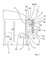
- the Fig. 1 shows a schematic representation of an embodiment of the height adjustment device 1 according to the invention in a fermenter of a bio-gas plant, the container. 3
- the agitator 2 is arranged.
- the agitator 2 can be moved up and down on the guide system 5 in the direction of the agitator movement XR, wherein the agitator 2 can be adjusted in height by the agitator stroke SR.
- the guide system 5 is mounted by means of one or more holders on the wall of the container 2, preferably placed on the floor and fixed with an upper bracket.
- the container 3 is a liquid 4, for example, a fermentation liquid.
- the container 3 is filled to a filling level height HF with the liquid 4, wherein the level height HF of the liquid 4 within the container 3 due to removal or addition of material or liquid can fluctuate.
- the level height HF is limited by a maximum filling height Hmax within the container 3.
- a rope 8 is non-positively connected to a Rrockwerksende 81. This rope is further guided over a arranged at the upper end of the guide system 5 pulley 83. Subsequently, the cable 8 is guided through a gas-tight cable feedthrough 84, wherein the gas-tight cable feedthrough 84 is in the upper region, at least above the maximum filling level height Hmax, in the wall of the container 3. On the outside of the container 3, the cable 8 is guided to a hydraulic cylinder 6, which serves as height adjustment, and is in operative connection with this.
- the hydraulic cylinder 6 consists of a cylinder 61 and a piston 62 with a piston rod. At the end of the piston rod is the distal end 64. The cylinder 61 and the head portion of the cylinder 61, the fixed end 63 of the hydraulic cylinder 6 is. The hydraulic cylinder 6 is fixedly secured to the cylinder 61 via a holder on the outer wall of the container 3 , wherein the holder or the container 3 serves as an abutment for the hydraulic cylinder 6 ..
- the piston 62 and the piston rod of the hydraulic cylinder 6 can perform a movement corresponding to the piston movement XK when pressurized.
- the total length of the hydraulic cylinder 6 and thereby the distance of the block recordings ⁇ x changed (see below).
- a block receiver 9 is provided at the top of the cylinder 61 of the hydraulic cylinder 6, the fixed end 63. Another block receiver 9 is arranged at the distal end 64 of the hydraulic cylinder 6.
- the block holders 9 have rollers 91, over which the cable 8 are guided.
- the hydraulic cylinder 6 is connected to the agitator 2 via the cable 8.
- the rope 8 in this case has the agitator end 81, which on the agitator. 2 is frictionally arranged and is deflected by the guide roller 83 at the upper end of the guide system 5 from a vertical orientation in a horizontal orientation and then leaves the interior of the container 3 through the gas-tight cable feedthrough 84 to the outside.
- the rope 8 On the outside of the container 3, the rope 8 is guided over the roller 91 of the upper block holder 9, the roller 91 also serves as a guide roller to convert the rope 8 from a horizontal orientation in a vertical orientation.
- a further deflection roller 83 may be arranged separately.
- the cable After the first contact with the roller 91 of the upper block holder 9, the cable is guided in a U-shape around the roller 91 of the lower block holder 9 and then directed upwards, where it ends in this embodiment on the block holder 9 in an attachment point 85.
- This end represents the working end 82 of the rope 8.
- This attachment point 85 serves as an abutment for the rope 8.
- the hydraulic cylinder 6 is pressurized with a hydraulic oil.
- the piston 62 of the hydraulic cylinder 6 performs a piston movement XK.
- the piston rod is extended in accordance with the stroke of the distal end, so that the rope 8, which is permanently held by the counterweight of the agitator 2 to tension, is moved so that the agitator 2 within the container 3 is moved up.
- This embodiment operates with a factor of 2, which means that a stroke movement of 1 meter of the piston SP, or the distal end SD causes a 2-meter stroke of the agitator SR.
- this requires twice the force that would have been necessary if there had been a direct operative connection between the hydraulic cylinder 6 and the agitator 2.
- the hydraulic cylinder is arranged with the associated components of the cable outside the container.
- the hydraulic cylinder with the associated components can also be arranged very well within the container, so that only the hydraulic pressure generating means and the operation are arranged outside the container.
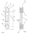
- Fig. 2 and Fig. 3 show a schematic representation of the hydraulic cylinder 6 as a pushing hydraulic cylinder in a plan view ( Fig. 2 ) and a side view ( Fig. 3 ).
- the rope 8 is guided by means of the corresponding reeving on the rollers 91 of the block holders 9 and attached non-positively at the working end 82 in an attachment point 85 to the lower block holder 9.
- the agitator 2 is lowered.
- the ratio 1: 6 it is meant that with a reduction of the distance ⁇ x by 1 m the agitator 2 is lowered by 6 m. The same applies to the upward movement of the agitator 2 when pressure is applied to the hydraulic cylinder 6.
- Fig. 3 shows correspondingly a schematic representation of the block recordings 9 with the already in Fig. 2 said six rollers 91 of the hydraulic cylinder 6 in a side view according to the in Fig. 2 illustrated hydraulic cylinder. 6
- the rope 8 is in accordance with the Einscherung on the six rollers 91, three rollers 91 per block recording 9, out.
- the working end 82 is attached to the attachment point 85 of the lower block holder 9.
- This arrangement represents a pulley with which it is possible with the aid of a correspondingly higher factorized (in this example, factor 6) increased force to implement a movement of the piston 62 of the hydraulic cylinder 6 in a movement of the agitator 2 corresponding to a 6-fold piston stroke SP ,
- Fig. 4 shows a further embodiment of the height adjustment means, namely the hydraulic cylinder 6 as a pulling hydraulic cylinder.
- the hydraulic pressure in the hydraulic system is generated with a hydraulic pressure generating means 7.
- the hydraulic system has hydraulic lines 71, through which the hydraulic pressure is distributed.
- two connections are provided on the hydraulic cylinder 6 in order to be able to build up a hydraulic pressure within the cylinder 61 on both sides of the piston 62.
- the hydraulic cylinder 6 is designed here as a double-acting hydraulic cylinder, wherein hydraulic oil can be introduced into the upper region of the cylinder 61 of the hydraulic cylinder 6, above the piston 62 and also below the piston 62 in the lower cylinder portion of the cylinder 61 of the hydraulic cylinder 6 can.
- the piston When introducing the hydraulic oil in the lower region of the cylinder, the piston performs a piston movement XK, in which case the upper block holder 9 is pulled with the or the roller 91 upwards. Accordingly, a downward movement of the upper block receiver 9 takes place when pressure is applied to the cylinder area located above the piston. In one-sided acting hydraulic cylinders 6 is sufficient for the downward movement and a lowering of the hydraulic pressure.
- the individual hydraulic lines 71 can be controlled via valves 73, so that hydraulic pressure is available only in the desired areas.
- a pressure relief valve 72 is preferably arranged just before the hydraulic cylinder 6 or in the hydraulic cylinder 6 itself. This pressure relief valve 72 is adjustable so that it triggers only at a certain pressure and so limits the pressure within the hydraulic cylinder. As a result, the maximum torque that can be generated by the hydraulic cylinder 6, limited.
- the overpressure valve 72 is used to prevent the cable from being over-inflated by excessive force being applied, for example, when the agitator 2 jams or canted on the guide system 5 and does not move further.
- the lower block holder 9 is arranged with his or her roller 91 on a solid surface.
- the lower block holder 9 serves with its role 91 as a deflection of the rope and as an abutment.
- Fig. 5 shows a schematic representation of the hydraulic cylinder 6 with a sheath.
- the casing of the hydraulic cylinder 6 consists of at least two individual sheathing.
- an inner single casing 65 is arranged above the cylinder 61 of the hydraulic cylinder 6.
- a scale 67 is applied on the outside of the inner single casing 65.
- an outer single casing 66 is arranged.
- the outer individual casing 66 is fixedly arranged on the lower block receptacle 9, so that when the distance ⁇ x of the block receptacles changes, the outer individual casing 66 is moved over the inner individual casing 65.
- the height of the agitator 2 can be read within the container 3 either directly or according to a factor. The determination is also possible via corresponding sensors, so that the control can be automated. The agitator 2 should always be kept below the level height HF so that it can work at all.
Landscapes
- Life Sciences & Earth Sciences (AREA)
- Chemical & Material Sciences (AREA)
- Chemical Kinetics & Catalysis (AREA)
- Engineering & Computer Science (AREA)
- Mechanical Engineering (AREA)
- Soil Sciences (AREA)
- Environmental Sciences (AREA)
- Geology (AREA)
- Structural Engineering (AREA)
- Mixers Of The Rotary Stirring Type (AREA)
- Apparatus Associated With Microorganisms And Enzymes (AREA)
Priority Applications (1)
| Application Number | Priority Date | Filing Date | Title |
|---|---|---|---|
| EP12169376A EP2500085A1 (fr) | 2009-07-15 | 2010-07-13 | Dispositif de réglage en hauteur pour centrale de malaxage ou de pompage immergée |
Applications Claiming Priority (1)
| Application Number | Priority Date | Filing Date | Title |
|---|---|---|---|
| DE202009005024U DE202009005024U1 (de) | 2009-07-15 | 2009-07-15 | Höhenverstellung für ein getauchtes Rühr- oder Pumpwerk |
Related Child Applications (2)
| Application Number | Title | Priority Date | Filing Date |
|---|---|---|---|
| EP12169376A Division EP2500085A1 (fr) | 2009-07-15 | 2010-07-13 | Dispositif de réglage en hauteur pour centrale de malaxage ou de pompage immergée |
| EP12169376.6 Division-Into | 2012-05-24 |
Publications (2)
| Publication Number | Publication Date |
|---|---|
| EP2275196A2 true EP2275196A2 (fr) | 2011-01-19 |
| EP2275196A3 EP2275196A3 (fr) | 2012-08-08 |
Family
ID=41078972
Family Applications (2)
| Application Number | Title | Priority Date | Filing Date |
|---|---|---|---|
| EP10401099A Withdrawn EP2275196A3 (fr) | 2009-07-15 | 2010-07-13 | Dispositif de réglage en hauteur pour mécanisme de malaxage ou de pompage immergé |
| EP12169376A Withdrawn EP2500085A1 (fr) | 2009-07-15 | 2010-07-13 | Dispositif de réglage en hauteur pour centrale de malaxage ou de pompage immergée |
Family Applications After (1)
| Application Number | Title | Priority Date | Filing Date |
|---|---|---|---|
| EP12169376A Withdrawn EP2500085A1 (fr) | 2009-07-15 | 2010-07-13 | Dispositif de réglage en hauteur pour centrale de malaxage ou de pompage immergée |
Country Status (2)
| Country | Link |
|---|---|
| EP (2) | EP2275196A3 (fr) |
| DE (1) | DE202009005024U1 (fr) |
Cited By (3)
| Publication number | Priority date | Publication date | Assignee | Title |
|---|---|---|---|---|
| CN104611194A (zh) * | 2015-03-03 | 2015-05-13 | 吉首大学 | 浓浆搅拌发酵罐 |
| CN113144979A (zh) * | 2021-05-18 | 2021-07-23 | 西安西北有色地质研究院有限公司 | 一种用于土壤粒度测定的智能搅拌装置 |
| CN117263105A (zh) * | 2023-11-16 | 2023-12-22 | 山东省环能设计院股份有限公司 | 用于光伏板组件安装的提升装置 |
Families Citing this family (6)
| Publication number | Priority date | Publication date | Assignee | Title |
|---|---|---|---|---|
| EP2689831A1 (fr) * | 2012-07-26 | 2014-01-29 | Michael Niederbacher | Installation de biogaz |
| EP2689830B1 (fr) * | 2012-07-26 | 2016-04-20 | Michael Niederbacher | Installation de biogaz |
| DE102012021206A1 (de) * | 2012-10-30 | 2014-04-30 | Uts Biogastechnik Gmbh | Fermenter einer Biogasanlage |
| DE102014116246A1 (de) | 2014-11-07 | 2016-05-12 | Uts Biogastechnik Gmbh | Höhenverstelleinrichtung und Verfahren zum Betreiben einer Rühreinrichtung |
| IT201900024490A1 (it) * | 2019-12-18 | 2021-06-18 | Ies Biogas S R L | Assieme di produzione di biogas o biometano con dispositivo di rilevamento posizione agitatore |
| DE102020102264A1 (de) * | 2020-01-30 | 2021-08-05 | Michael Niederbacher | Fermenterbehälter einer Biogasanlage mit wenigstens einem höhenverstellbaren Rührwerk |
Citations (4)
| Publication number | Priority date | Publication date | Assignee | Title |
|---|---|---|---|---|
| DE2855206A1 (de) * | 1978-12-21 | 1980-06-26 | Hoelz Otto Masch Gmbh | Ruehrgeraete fuer fluessigmist und abwasser |
| DE20316252U1 (de) * | 2003-10-23 | 2004-02-19 | Harbs, Volker, Dipl.-Ing. | Schwimmschlamm-Saugmischer zum Ansaugen, Grobentgasen und Untermischen von Schwimmschlämmen |
| DE102007012014A1 (de) * | 2007-03-13 | 2008-09-18 | Uts Biogastechnik Gmbh | Verfahren zum Ein- und Ausbau eines Rührgeräts in eine Biogasanlage und Tragarmverlängerung zur Durchführung des Verfahrens |
| EP2213720A1 (fr) * | 2009-01-28 | 2010-08-04 | Michael Dr. Niederbacher | Installation de biogaz dotée d'un appareil d'agitation submersible réglable en hauteur |
Family Cites Families (9)
| Publication number | Priority date | Publication date | Assignee | Title |
|---|---|---|---|---|
| DE1026060B (de) * | 1952-12-04 | 1958-03-13 | Rutger Manten | Hydraulische Hebevorrichtung fuer Lasten |
| FR1475099A (fr) * | 1966-03-18 | 1967-03-31 | H C Pope Ltd Et Henry | Dispositif actionné hydrauliquement pour faire monter et descendre des charges |
| JPS63106289A (ja) * | 1986-10-22 | 1988-05-11 | 株式会社日立製作所 | 流体圧エレベ−タ |
| DE4015478C1 (fr) | 1990-05-14 | 1991-09-12 | Abs Pumpen Ag, 5204 Lohmar, De | |
| DE4342716A1 (de) * | 1993-12-15 | 1995-06-22 | Zasche Foerdertechnik Gmbh | Hubvorrichtung für ein Handhabungsgerät |
| DE9414920U1 (de) | 1994-09-14 | 1995-01-12 | Streisal Tauchmotor Gmbh | Mischeinrichtung für Flüssigkeiten unterhalb explosiver Atmosphären |
| DE19732198C1 (de) | 1997-07-26 | 1998-10-08 | Uts Umwelt Technik Sued Gmbh | Hubvorrichtung für ein Aggregat, insbesondere für ein Tauchmotorrührgerät, in einem dichten Behälter |
| DE102007009451B4 (de) | 2007-02-27 | 2010-04-01 | Uts Biogastechnik Gmbh | Biogasanlagen-Fermenter mit einem motorisch höhenverstellbaren Tauchmotorrührgerät |
| DE202009001118U1 (de) * | 2008-11-11 | 2009-04-09 | Streisal Gmbh | Verstelleinrichtung für Tauchmotorrührwerke |
-
2009
- 2009-07-15 DE DE202009005024U patent/DE202009005024U1/de not_active Expired - Lifetime
-
2010
- 2010-07-13 EP EP10401099A patent/EP2275196A3/fr not_active Withdrawn
- 2010-07-13 EP EP12169376A patent/EP2500085A1/fr not_active Withdrawn
Patent Citations (4)
| Publication number | Priority date | Publication date | Assignee | Title |
|---|---|---|---|---|
| DE2855206A1 (de) * | 1978-12-21 | 1980-06-26 | Hoelz Otto Masch Gmbh | Ruehrgeraete fuer fluessigmist und abwasser |
| DE20316252U1 (de) * | 2003-10-23 | 2004-02-19 | Harbs, Volker, Dipl.-Ing. | Schwimmschlamm-Saugmischer zum Ansaugen, Grobentgasen und Untermischen von Schwimmschlämmen |
| DE102007012014A1 (de) * | 2007-03-13 | 2008-09-18 | Uts Biogastechnik Gmbh | Verfahren zum Ein- und Ausbau eines Rührgeräts in eine Biogasanlage und Tragarmverlängerung zur Durchführung des Verfahrens |
| EP2213720A1 (fr) * | 2009-01-28 | 2010-08-04 | Michael Dr. Niederbacher | Installation de biogaz dotée d'un appareil d'agitation submersible réglable en hauteur |
Cited By (4)
| Publication number | Priority date | Publication date | Assignee | Title |
|---|---|---|---|---|
| CN104611194A (zh) * | 2015-03-03 | 2015-05-13 | 吉首大学 | 浓浆搅拌发酵罐 |
| CN113144979A (zh) * | 2021-05-18 | 2021-07-23 | 西安西北有色地质研究院有限公司 | 一种用于土壤粒度测定的智能搅拌装置 |
| CN117263105A (zh) * | 2023-11-16 | 2023-12-22 | 山东省环能设计院股份有限公司 | 用于光伏板组件安装的提升装置 |
| CN117263105B (zh) * | 2023-11-16 | 2024-03-08 | 山东省环能设计院股份有限公司 | 用于光伏板组件安装的提升装置 |
Also Published As
| Publication number | Publication date |
|---|---|
| DE202009005024U1 (de) | 2009-09-17 |
| EP2500085A1 (fr) | 2012-09-19 |
| EP2275196A3 (fr) | 2012-08-08 |
Similar Documents
| Publication | Publication Date | Title |
|---|---|---|
| EP2275196A2 (fr) | Dispositif de réglage en hauteur pour mécanisme de malaxage ou de pompage immergé | |
| EP3280674B1 (fr) | Dispositif de transport | |
| DE1484577B1 (de) | Vorrichtung zum Eintreiben oder Ziehen von Pfaehlen,Spundbohlen od.dgl. | |
| DE102015116506A1 (de) | Mobile Schachtwinde | |
| EP2857493A1 (fr) | Agitateur pour un récipient, récipient et procédé de montage d'un agitateur dans un récipient | |
| EP1130084B1 (fr) | Installation de biogaz pour la fermentation de matériaux organiques | |
| EP3590881A1 (fr) | Dispositif de transport | |
| WO2020156856A1 (fr) | Dispositif de serrage et de levage | |
| DE3516289A1 (de) | Seegangsfolgeeinrichtung | |
| DE19982997B4 (de) | Vorrichtung zum Untersuchen, Entnehmen oder Extrahieren eines Inhalts eines Silos an einen präzisen Punkt unter einer Platte | |
| EP1531139A1 (fr) | Moteur sans châssis pour ascenseur | |
| EP3819434B1 (fr) | Procédé et dispositif de fraisage de paroi de fente permettant de créer une fente fraisée dans le sol | |
| DE19933771B4 (de) | Kran | |
| DE102004061182A1 (de) | Scherenhubtisch | |
| DE19605949C2 (de) | Schachthaspel | |
| EP3290383B1 (fr) | Dispositif destiné à lever, abaisser ou maintenir une charge | |
| EP1774999A1 (fr) | Unité d'entraînement | |
| EP3904632B1 (fr) | Procédé et dispositif de levage d'une tige de forage | |
| EP1975113B1 (fr) | Dispositif de câble de commande destiné à l'utilisation lors de la pose ou du renouvellement de conduites dans le sol | |
| DE202013006584U1 (de) | Ballastvorrichtung zur Erzeugung einer Windenvorspannung | |
| DE102013113574A1 (de) | Hubgerüst mit hydraulikfreiem Hubantrieb | |
| EP3473566B1 (fr) | Système de transport destiné au transport des objets dans une installation de traitement par immersion | |
| DE102004019914A1 (de) | Mehrstufiges Hubsystem für einen Gabelstapler | |
| DE3443191C2 (de) | Stoßschutzeinrichtung für das Abbremsen von Schiffen in Schleusenanlagen | |
| DE1032907B (de) | Wippkran mit hydrostatischem Hubwerksantrieb |
Legal Events
| Date | Code | Title | Description |
|---|---|---|---|
| PUAI | Public reference made under article 153(3) epc to a published international application that has entered the european phase |
Free format text: ORIGINAL CODE: 0009012 |
|
| AK | Designated contracting states |
Kind code of ref document: A2 Designated state(s): AL AT BE BG CH CY CZ DE DK EE ES FI FR GB GR HR HU IE IS IT LI LT LU LV MC MK MT NL NO PL PT RO SE SI SK SM TR |
|
| AX | Request for extension of the european patent |
Extension state: BA ME RS |
|
| RAP1 | Party data changed (applicant data changed or rights of an application transferred) |
Owner name: MT-ENERGIE GMBH |
|
| RIC1 | Information provided on ipc code assigned before grant |
Ipc: B66F 7/04 20060101ALI20120308BHEP Ipc: B66D 1/48 20060101ALI20120308BHEP Ipc: B66D 1/44 20060101ALI20120308BHEP Ipc: B01F 7/00 20060101AFI20120308BHEP |
|
| PUAL | Search report despatched |
Free format text: ORIGINAL CODE: 0009013 |
|
| AK | Designated contracting states |
Kind code of ref document: A3 Designated state(s): AL AT BE BG CH CY CZ DE DK EE ES FI FR GB GR HR HU IE IS IT LI LT LU LV MC MK MT NL NO PL PT RO SE SI SK SM TR |
|
| AX | Request for extension of the european patent |
Extension state: BA ME RS |
|
| RIC1 | Information provided on ipc code assigned before grant |
Ipc: B66D 1/48 20060101ALI20120629BHEP Ipc: B66D 1/44 20060101ALI20120629BHEP Ipc: B01F 7/00 20060101AFI20120629BHEP Ipc: B66F 7/04 20060101ALI20120629BHEP |
|
| STAA | Information on the status of an ep patent application or granted ep patent |
Free format text: STATUS: THE APPLICATION IS DEEMED TO BE WITHDRAWN |
|
| 18D | Application deemed to be withdrawn |
Effective date: 20130201 |