EP2274825B1 - Systeme d'alimentation electrique - Google Patents
Systeme d'alimentation electrique Download PDFInfo
- Publication number
- EP2274825B1 EP2274825B1 EP09741948.5A EP09741948A EP2274825B1 EP 2274825 B1 EP2274825 B1 EP 2274825B1 EP 09741948 A EP09741948 A EP 09741948A EP 2274825 B1 EP2274825 B1 EP 2274825B1
- Authority
- EP
- European Patent Office
- Prior art keywords
- power supply
- supply device
- converter
- power converter
- power
- Prior art date
- Legal status (The legal status is an assumption and is not a legal conclusion. Google has not performed a legal analysis and makes no representation as to the accuracy of the status listed.)
- Active
Links
- 238000004146 energy storage Methods 0.000 claims description 17
- 239000004065 semiconductor Substances 0.000 claims description 16
- 239000003990 capacitor Substances 0.000 claims description 15
- 238000004804 winding Methods 0.000 description 10
- 230000005540 biological transmission Effects 0.000 description 6
- 238000010586 diagram Methods 0.000 description 3
- 230000008878 coupling Effects 0.000 description 2
- 238000010168 coupling process Methods 0.000 description 2
- 238000005859 coupling reaction Methods 0.000 description 2
- 238000005516 engineering process Methods 0.000 description 2
- 230000007704 transition Effects 0.000 description 2
- 238000004891 communication Methods 0.000 description 1
- 238000006073 displacement reaction Methods 0.000 description 1
- 230000002349 favourable effect Effects 0.000 description 1
- 238000009413 insulation Methods 0.000 description 1
- 238000004519 manufacturing process Methods 0.000 description 1
- 210000002023 somite Anatomy 0.000 description 1
Images


Classifications
-
- H—ELECTRICITY
- H02—GENERATION; CONVERSION OR DISTRIBUTION OF ELECTRIC POWER
- H02M—APPARATUS FOR CONVERSION BETWEEN AC AND AC, BETWEEN AC AND DC, OR BETWEEN DC AND DC, AND FOR USE WITH MAINS OR SIMILAR POWER SUPPLY SYSTEMS; CONVERSION OF DC OR AC INPUT POWER INTO SURGE OUTPUT POWER; CONTROL OR REGULATION THEREOF
- H02M7/00—Conversion of ac power input into dc power output; Conversion of dc power input into ac power output
- H02M7/42—Conversion of dc power input into ac power output without possibility of reversal
- H02M7/44—Conversion of dc power input into ac power output without possibility of reversal by static converters
- H02M7/48—Conversion of dc power input into ac power output without possibility of reversal by static converters using discharge tubes with control electrode or semiconductor devices with control electrode
- H02M7/483—Converters with outputs that each can have more than two voltages levels
- H02M7/4835—Converters with outputs that each can have more than two voltages levels comprising two or more cells, each including a switchable capacitor, the capacitors having a nominal charge voltage which corresponds to a given fraction of the input voltage, and the capacitors being selectively connected in series to determine the instantaneous output voltage
Definitions
- the invention relates to a power supply device according to the preamble of claim 1.
- variable-speed drives consisting of an electric motor and a pump or a compressor, supplied on the seabed with energy from an electrical supply network on land.
- the distance between infeed on land and propulsion at the seabed can be several hundred kilometers with sea depths of several kilometers.
- Variable speed drives for underwater applications also referred to as subsea applications, are used, for example, in oil and gas production on the seabed. These variable-speed drives are known to be powered by means of a voltage source inverter from an electrical supply network with energy.
- inverter topologies include 3-level neutral-point-clamped (3L-NPC) 12-pulse diode feed, 4-level flying capacitors (4L-FC) with 12-pulse diode feed, Series Connected H-Bridge cell inverters with 2-level H-bridges per cell (SC-HB (2L)) and a Series-Connected H-Bridge cell inverter with 3-level H-bridge per cell (SC-HB (3L)).
- Modular power converter concept for mains coupling application at high voltages is a converter with a mains and load side power converter, the DC side connected to each other electrically conductive , in which a modular multipoint power converter, also referred to as a modular multilevel converter (M2C), is used as the power converter.
- M2C modular multilevel converter
- Such a voltage source converter with a mains and load side converter in M2C topology has no voltage intermediate circuit constructed from intermediate circuit capacitors more compared to the already described voltage source inverter.
- Each valve branch of each phase module of the inverter in M2C topology has at least one two-pole subsystem. The number of subsystems used in each valve branch determines the frequency of a phase output voltage.
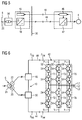
- FIG. 2 a further known power supply device of a arranged on the seabed speed variable drive is shown.
- This embodiment differs from the embodiment according to FIG. 1 in that the AC cable 14 is linked by means of a transformer 32 to outputs of the self-commutated pulse-controlled converter 12 of the voltage intermediate-circuit converter 2.
- this AC power cable 14 is connected by means of a second transformer 34 to terminals of the seabed electric motor 14.
- a generated inverter voltage is transformed to a potential higher than the potential of the rated voltage of the electric motor 4. After transmission, this potential is transformed back to nominal potential of the motor.
- the increased transmission voltage results in lower ohmic power losses.
- the AC cable 14 may have a smaller cable cross-section, thereby allowing a more favorable design of the cable 14. This allows a greater distance between inverter 2 and motor 4 over the embodiment according to FIG. 1 be bridged.
- the voltage intermediate-circuit converter 2 with mains-side converter transformer 6 is according to FIG. 3 arranged on the seabed in the immediate vicinity of the electric motor 4 of the variable speed drive.
- a mains transformer 36 is provided, which is the primary side connected to the dining supply network 8, in particular with the feed point 26, and the secondary side electrically connected to the AC cable 14.
- FIG. 4 is a multi-motor variant of the power supply device according to FIG. 4 shown schematically.
- Each motor of a variable-speed drive is coupled to a voltage source inverter 2 with line-side converter transformer 6.
- the AC power cable 14 is linked to an AC busbar 38 to which are connected the plurality of power converter powered drives.
- the AC cable 14 may be provided on the load side of the seabed with another transformer 40, which is the secondary side connected to the AC busbar 38. Since this further transformer 40 is not absolutely necessary, this is shown by broken lines. With this further transformer 40, the AC busbar 38 has a potential below the potential of the transmission voltage, but above the potential of the rated voltage of the electric motor 4 of a variable-speed drive.
- the distance between entry point 26 on land and drive at the seabed is the same as in the other variants FIGS. 1 to 3 still limited.
- the number of plant parts on the seabed has multiplied. All plant components arranged at the seabed are encapsulated, in particular each be housed in a pressure vessel.
- the one self-commutated pulse-controlled converter is arranged by means of a mains transformer at a feed point of a feeding network on land, whereas the second self-commutated pulse-controlled converter is arranged on a platform on the sea.
- a direct voltage cable a submarine cable is provided, which has a length of about 300km. Between these two converters no communication is necessary. Only the value of the DC voltage at both ends of the DC cable is needed.
- the converter station on land regulates the transmission voltage and the converter station on the platform at sea regulates the active power. Also in this power supply device, the distance between the feed point and platform is also limited.
- the invention is based on the object, the known power supply device such that the distance between the feed point to land and drive at the seabed is much larger.
- a power converter with distributed energy storage is provided as load-side self-commutated power converter of the upper and lower valve branch of each phase module at least two electrically connected in series bipolar subsystems
- the power supply device according to the invention no energy storage in the DC intermediate circuit more, so that now that the network-side converter and the load-side converter of the power supply device according to the invention electrically connecting DC cables can bridge much greater distances.
- the power converter with distributed energy stores of the power supply device according to the invention can be arranged on the motor to be fed on the seabed and its power converter on shore.
- a power converter with a plurality of bipolar subsystems as a load-side power converter of the power supply device of the voltage source inverter can be divided between land and seabed.
- the load-side converter with distributed energy storage of this power supply device on the seabed.
- the value of the converter output voltage and thus the motor voltage is determined, no transformer is needed at the seabed.
- the finely graded output voltage form of the load-side power converter with distributed energy storage devices of the power supply device according to the invention submerged motors with reduced requirements for the winding insulation. Since a high motor voltage can still be set regardless of the use of a transformer, connecting lines and feedthroughs to the motor can be designed for smaller currents. In addition, it can be avoided at higher power motors with multiple winding systems.
- the load-side converter with distributed energy stores of the power supply device per valve branch only consists of a number of electrically connected in series bipolar subsystems, the availability of the power supply device can be substantially increased by adding redundant bipolar subsystems.
- signal electronics of the load-side arranged on the seabed power converter with distributed energy storage on land is arranged.
- This signal electronics is connected by means of a data cable signal technology with control inputs of the load-side converter with distributed energy storage on the seabed.
- the network-side uncontrolled power converter by means of the DC cable with a arranged on seabed DC busbar is electrically conductively connected.
- a plurality of load-side converters with distributed energy storage can be connected in each case with an output-side motor of a variable speed drive.
- FIG. 5 a first variant of the power supply device according to the invention is shown schematically.
- 42 denotes a load-side power converter with distributed energy stores
- 44 denotes a DC cable
- 46 denotes a control unit.
- the network side and the Load-side power converters 10 and 42 are connected to one another by means of the DC cable 44 on the DC voltage side.
- the control unit 46 of this load-side power converter 42 with distributed energy stores is connected by means of a data cable 18 with the signal electronics 16 of the power supply device, which is associated with the network-side converter 10.
- the network-side power converter 10 which is designed as an uncontrolled power converter, is connected on the alternating voltage side by means of the power transformer 36 to the feed point 26 of the feeding supply network 8.
- the load-side power converter 42 is arranged with distributed energy storage on the seabed. All other components of this power supply device are arranged on land. The transition from land to sea is also indicated by a wavy line 30 in this figure.
- a line-side converter 10 a diode feed is provided, which is designed in the simplest case 6-pulse. If current harmonics in the network are not to be present if possible, and if so, then only with a small amplitude, the diode feed 10 must be designed, for example, 12, 18 or 24-pulse.
- FIG. 6 is a block diagram of an advantageous embodiment of the power supply device according to the invention schematically illustrated.
- the diode feed 10 has two 6-pulse diode bridges 48 and 50, which are each connected on the alternating voltage side to a secondary winding 22 and 20 of the converter transformer 6 and the DC side electrically in series.
- the load-side power converter 42 with distributed energy storage devices has a plurality of phase modules 52, which are electrically connected in parallel on the DC voltage side.
- a positive and negative DC bus bar P 0W and N 0W are provided for the parallel connection of these phase modules 52.
- a positive and negative DC bus bar P 0W and N 0W are provided. Between these two DC busbars P 0W and N 0W falls from an unspecified DC voltage.
- Each phase module 52 has an upper one and a lower valve branch T1, T2 and T3, T4 and T5, T6, respectively.
- Each valve branch T1,..., T6 has at least two two-pole subsystems 54.
- each valve branch has four two-pole subsystems 54.
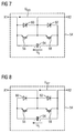
- the bipolar subsystems 54 are electrically connected in series. Embodiments of these bipolar subsystems 54 are shown in FIGS FIGS. 7 and 8 shown.
- Each connection point of two valve branches T1, T2 or T3, T4 or T5, T6 form an AC-side terminal L1 or L2 or L3.
- At these AC-side terminals L1, L2 and L3 is in the FIG. 5 shown electric motor 4 connected.
- the DC busbars P 0W and N 0W of the load-side power converter 42 with distributed energy storage devices and the DC busbars P 0G and N 0G of the network-side power converter are electrically conductively connected to each other by means of the DC cable 44.
- FIG. 7 A first embodiment of a bipolar subsystem 54 is shown.
- This bipolar subsystem 54 has two turn-off semiconductor switches 56 and 58, two diodes 60 and 62 and a unipolar storage capacitor 64.
- the two turn-off semiconductor switches 56 and 58 are electrically connected in series, wherein this series circuit is electrically connected in parallel to the storage capacitor 64.
- Each turn-off semiconductor switch 56 and 58, one of the two diodes 60 and 62 is electrically connected in parallel, that this is connected in antiparallel to the corresponding turn-off semiconductor switch 56 and 58.
- the unipolar storage capacitor 64 of the bipolar subsystem 54 consists of either a capacitor or a capacitor bank of a plurality of such capacitors with a resulting capacitance C 0 .
- connection point of emitter of the turn-off semiconductor switch 56 and anode of the diode 60 form a terminal X1 of the subsystem 54.
- connection point of the two turn-off semiconductor switch 56th and 58 and the two diodes 60 and 62 form a second terminal X2 of the bipolar subsystem 54.
- connection point forms the first connection terminal X1.
- the connection point of drain of the turn-off semiconductor switch 58 and cathode of the diode 62 forms the second terminal X2 of the bipolar subsystem 54th
- the bipolar subsystem 54 may assume three switching states. In the switching state I, the turn-off semiconductor switch 56 is turned on and the turn-off semiconductor switch 58 is turned off. In this switching state I, the terminal voltage U X21 of the bipolar subsystem 54 is equal to zero. In switching state II, the turn-off semiconductor switch 56 are turned off and the turn-off semiconductor switch 58 is turned on. In this switching state II, the terminal voltage U X21 of the bipolar subsystem 54 is equal to the voltage U C on the storage capacitor 64. In normal, trouble-free operation, only these two switching states I and II are used. In switching state III, both turn-off semiconductor switches 56 and 58 are turned off.
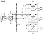
- FIG. 9 a second variant of the power supply device according to the invention is illustrated schematically.
- This second variant differs in that a DC busbar 66 is provided.
- three load-side converter 42 are connected with distributed energy storage devices each with a load-side motor 4 of a variable speed drive.
- This DC busbar 66 is linked by means of the DC cable 44 with DC terminals of the network-side converter 10.
- a data busbar 68 is provided, on the one hand, the control units 46 of the load-side power converter 42 with distributed energy storage and on the other hand, the data cable 18 are connected.
- the land-based signal electronics 16 of the power supply device according to the invention in each case with a control unit 46 of a respective arranged on the seabed load-side converter 42 with distributed energy storage signal technology connected.
- a DC busbar 66 By using a DC busbar 66, the cable costs for a multi-motor drive and the effort for assembly are reduced.
- variable-speed drives of subsea applications for example oil and gas conveyors
- a feeding supply network wherein the distance between the feed on land and the drive on the seabed can be several hundred kilometers at sea depths of several kilometers
Landscapes
- Engineering & Computer Science (AREA)
- Power Engineering (AREA)
- Inverter Devices (AREA)
- Rectifiers (AREA)
- Control Of Eletrric Generators (AREA)
- Other Liquid Machine Or Engine Such As Wave Power Use (AREA)
Claims (11)
- Dispositif d'alimentation en courant d'un entraînement disposé au fond de la mer et à vitesse de rotation variable, dans lequel ce dispositif d'alimentation en courant a un convertisseur (10) de courant du côté du réseau et un convertisseur (12) du côté de la charge, qui sont reliés entre eux d'une manière conductrice de l'électricité du côté de la tension continue au moyen d'un câble (44) de tension continue, dont le convertisseur (10) du côté du réseau est relié à terre à un réseau (8) d'alimentation,
caractérisé en ce qu'il est prévu, du côté du réseau, un convertisseur (10) non commandé et, du côté de la charge, un convertisseur (42) à accumulateurs d'énergie répartis, en ce que chaque module (52) de phase du convertisseur (42) à accumulateurs d'énergie répartis a une branche (T1, T3, T5; T2, T4, T6) de soupape supérieure et inférieure ayant au moins deux sous-systèmes (54) bipolaires montés en série, en ce que le convertisseur (42) à accumulateurs d'énergie répartis est disposé au fond de la mer à proximité immédiate de l'entraînement à vitesse de rotation variable et en ce qu'une électronique (16) de signalisation du convertisseur (42) à accumulateurs d'énergie répartis est à terre. - Dispositif d'alimentation en courant suivant la revendication 1,
caractérisé en ce que le convertisseur (10) non commandé du côté du réseau est relié d'une manière conductrice de l'électricité au moyen du câble (44) de courant continu à une barre (66) collectrice de tension continue disposée au fond de la mer, barre à laquelle est connecté au moins un convertisseur (42) du côté de la charge à commutation automatique à entraînement à vitesse de rotation variable du côté de la tension alternative. - Dispositif d'alimentation en courant suivant la revendication 1 ou 2,
caractérisé en ce que le convertisseur (10) non commandé du côté du réseau est disposé sur une plateforme en mer. - Dispositif d'alimentation en courant suivant l'une des revendications précédentes,
caractérisé en ce qu'il est prévu un redresseur à diode comme convertisseur (10) non commandé du côté du réseau. - Dispositif d'alimentation en courant suivant la revendication 4,
caractérisé en ce que le redresseur à diode est réalisé à 12 impulsions. - Dispositif d'alimentation en courant suivant la revendication 4,
caractérisé en ce que le redresseur à diode est réalisé à 18 impulsions. - Dispositif d'alimentation en courant suivant la revendication 4,
caractérisé en ce que le redresseur à diode est réalisé à 24 impulsions. - Dispositif d'alimentation en courant suivant l'une des revendications précédentes,
caractérisé en ce qu'un sous-système (54) bipolaire a deux commutateurs (56, 58) à semiconducteurs montés en série et pouvant être ouverts et un condensateur (64) d'accumulation, ce circuit série étant monté électriquement en parallèle au condensateur (64) d'accumulation, dans lequel un point de liaison des deux commutateurs (56, 58) à semiconducteurs pouvant être ouverts forme une première borne (X2, X1) de connexion du sous-système (54) bipolaire, un pôle du condensateur (64) d'accumulation formant une deuxième borne (X1, X2) de connexion de ce sous-système bipolaire. - Dispositif d'alimentation en courant suivant la revendication 8,
caractérisé en ce qu'il est prévu, comme commutateur (56, 58) à semiconducteurs pouvant être ouvert, un insulated gate bipolar transistor. - Dispositif d'alimentation en courant suivant l'une des revendications précédentes,
caractérisé en ce que l'entraînement à vitesse de rotation variable a un moteur électrique ayant une pompe du côté de l'induit. - Dispositif d'alimentation en courant suivant l'une des revendications 1 à 9,
caractérisé en ce que l'entraînement à vitesse de rotation variable a un moteur électrique ayant un compresseur du côté de l'induits.
Applications Claiming Priority (2)
| Application Number | Priority Date | Filing Date | Title |
|---|---|---|---|
| DE102008022618A DE102008022618A1 (de) | 2008-05-07 | 2008-05-07 | Stromversorgungseinrichtung |
| PCT/EP2009/053654 WO2009135730A1 (fr) | 2008-05-07 | 2009-03-27 | Système d'alimentation électrique |
Publications (2)
| Publication Number | Publication Date |
|---|---|
| EP2274825A1 EP2274825A1 (fr) | 2011-01-19 |
| EP2274825B1 true EP2274825B1 (fr) | 2016-08-10 |
Family
ID=40875153
Family Applications (1)
| Application Number | Title | Priority Date | Filing Date |
|---|---|---|---|
| EP09741948.5A Active EP2274825B1 (fr) | 2008-05-07 | 2009-03-27 | Systeme d'alimentation electrique |
Country Status (10)
| Country | Link |
|---|---|
| US (1) | US8476854B2 (fr) |
| EP (1) | EP2274825B1 (fr) |
| JP (1) | JP5506784B2 (fr) |
| CN (1) | CN102017385B (fr) |
| BR (1) | BRPI0912423B1 (fr) |
| CY (1) | CY1118133T1 (fr) |
| DE (1) | DE102008022618A1 (fr) |
| DK (1) | DK2274825T3 (fr) |
| RU (1) | RU2479914C2 (fr) |
| WO (1) | WO2009135730A1 (fr) |
Families Citing this family (42)
| Publication number | Priority date | Publication date | Assignee | Title |
|---|---|---|---|---|
| DE102005045091B4 (de) | 2005-09-21 | 2007-08-30 | Siemens Ag | Steuerverfahren zur Redundanznutzung im Störungsfall eines mehrphasigen Stromrichters mit verteilten Energiespeichern |
| US8692408B2 (en) * | 2008-12-03 | 2014-04-08 | General Electric Company | Modular stacked subsea power system architectures |
| EP2486645B1 (fr) * | 2009-10-06 | 2018-01-10 | ABB Research Ltd. | Structure modifiée de convertisseur de source de tension |
| NO332768B1 (no) * | 2009-12-16 | 2013-01-14 | Smartmotor As | System for drift av langstrakte elektriske maskiner |
| CN103119531B (zh) | 2010-08-04 | 2015-08-05 | 柯蒂斯-赖特机电公司 | 耦联到电流源电源上的m2lc系统 |
| WO2012033958A1 (fr) | 2010-09-09 | 2012-03-15 | Curtiss-Wright Electro-Mechanical Corporation | Système et procédé pour le contrôle d'un système m2lc |
| RU2571117C2 (ru) * | 2010-09-13 | 2015-12-20 | Акер Сабси АС | Система передачи электроэнергии под водой для обеспечения работы высокооборотного двигателя |
| US8649187B2 (en) | 2010-09-21 | 2014-02-11 | Curtiss-Wright Electro-Mechanical Corporation | Two-terminal M2LC subsystem and M2LC system including same |
| US9450412B2 (en) * | 2010-12-22 | 2016-09-20 | General Electric Company | Method and system for control power in remote DC power systems |
| US8624431B2 (en) * | 2011-02-26 | 2014-01-07 | General Electric Company | System and method for power sharing of front-end converters without communication link in a modular-stacked DC transmission system |
| RU2548174C1 (ru) | 2011-03-02 | 2015-04-20 | Абб Ас | Защита блока управления работой, подключенного к электрической машине по длинному кабелю |
| DE102011006987A1 (de) | 2011-04-07 | 2012-10-11 | Siemens Aktiengesellschaft | Modulares Stromrichterschranksystem |
| AU2011250865A1 (en) * | 2011-08-15 | 2013-03-07 | Saminco Inc. | DC trailing cable system for tethered mining vehicles |
| GB2493938B (en) * | 2011-08-23 | 2014-08-13 | Framo Eng As | Double motor pump with variable speed drive |
| EP2626994B1 (fr) * | 2012-02-08 | 2019-04-03 | GE Oil & Gas UK Limited | Fourniture d'une alimentation électrique pour équipement sous-marin |
| MX345133B (es) | 2012-03-09 | 2017-01-18 | Benshaw Inc | Sistema m2lc y metodo para controlar el mismo. |
| WO2013132098A2 (fr) * | 2012-03-09 | 2013-09-12 | Abb Technology Ag | Unité électrique pour centrale de pompage |
| WO2014046555A1 (fr) * | 2012-09-21 | 2014-03-27 | Auckland Uniservices Limited | Améliorations dans ou concernant des convertisseurs multi-niveau modulaires |
| DK2713468T3 (da) * | 2012-09-28 | 2019-11-04 | Ge Energy Power Conversion Technology Ltd | Elektriske energioverførselssystemer |
| EP2762347A1 (fr) | 2013-01-31 | 2014-08-06 | Siemens Aktiengesellschaft | Convertisseur haute fréquence modulaire et procédé de fonctionnement de celui-ci |
| JP2016510203A (ja) * | 2013-02-28 | 2016-04-04 | シーメンス アクチエンゲゼルシヤフトSiemens Aktiengesellschaft | ダイオード整流器を有する変換器ステーション |
| EP2941822B1 (fr) * | 2013-02-28 | 2022-08-24 | Siemens Energy Global GmbH & Co. KG | Poste de conversion équipé d'un redresseur à diodes |
| EP2773032A1 (fr) * | 2013-03-01 | 2014-09-03 | GE Energy Power Conversion Technology Ltd | Convertisseur alimenté par une source de courant imposé avec des composants blocable et une commutation spéciale |
| US9859806B2 (en) * | 2014-03-14 | 2018-01-02 | Abb Research Ltd. | Method and apparatus for obtaining electricity from offshore wind turbines |
| BR112016026060B1 (pt) | 2014-05-07 | 2022-08-02 | Aker Solutions As | Conjunto de fornecimento de energia e método associado |
| EP2961021A1 (fr) * | 2014-06-27 | 2015-12-30 | Siemens Aktiengesellschaft | Système de distribution d'énergie sous-marine et son procédé |
| NO337348B1 (no) * | 2014-08-18 | 2016-03-21 | Aker Subsea As | Drivenhet over vannflaten med variabel hastighet for store pumper og kompressorer. |
| EP2996238A1 (fr) * | 2014-09-09 | 2016-03-16 | ABB Technology Ltd | Convertisseur sous-marin modulaire |
| US20160215769A1 (en) * | 2015-01-27 | 2016-07-28 | Baker Hughes Incorporated | Systems and Methods for Providing Power to Well Equipment |
| EP3131377A1 (fr) | 2015-08-14 | 2017-02-15 | Siemens Aktiengesellschaft | Modulateur de phase pour convertisseur de courant |
| GB2545455A (en) * | 2015-12-17 | 2017-06-21 | General Electric Technology Gmbh | Power supply apparatus |
| CN105807664A (zh) * | 2016-04-25 | 2016-07-27 | 浙江大学 | 一种基于高低电平数字信号控制的水下分支器 |
| DE102016209983A1 (de) | 2016-06-07 | 2017-12-07 | Leybold Gmbh | Vorrichtung und Verfahren zum Antreiben einer Vakuumpumpe |
| US10153640B2 (en) * | 2016-11-30 | 2018-12-11 | State Grid Jiangsu Electric Power Research Institute | Unified power flow controller and control method thereof |
| EP3407447A1 (fr) | 2017-05-24 | 2018-11-28 | Siemens Aktiengesellschaft | Réseau de tension électrique continue à haute redondance |
| JP7066879B2 (ja) * | 2019-01-24 | 2022-05-13 | 株式会社日立産機システム | 電力変換システム |
| CN110112730A (zh) * | 2019-05-15 | 2019-08-09 | 全球能源互联网研究院有限公司 | 一种输电系统 |
| US20210320578A1 (en) | 2020-04-08 | 2021-10-14 | Halliburton Energy Services, Inc. | Axial Flux Submersible Electric Motor |
| CN113765425B (zh) | 2020-06-01 | 2024-08-20 | 台达电子企业管理(上海)有限公司 | 模块化多电平换流器的控制方法及控制系统与输电系统 |
| CN113765426B (zh) * | 2020-06-01 | 2024-08-20 | 台达电子企业管理(上海)有限公司 | 模块化多电平换流器的控制方法及控制系统与输电系统 |
| CN111799661B (zh) * | 2020-06-04 | 2022-05-20 | 许继集团有限公司 | 一种模块化海上柔性直流输电系统换流站 |
| US11677264B2 (en) * | 2020-11-09 | 2023-06-13 | Electronic Power Design, Inc. | System and method for a backup power supply |
Family Cites Families (22)
| Publication number | Priority date | Publication date | Assignee | Title |
|---|---|---|---|---|
| JPH0677710B2 (ja) * | 1986-05-15 | 1994-10-05 | 兵神装備株式会社 | 定量塗布装置 |
| US5050058A (en) * | 1990-08-14 | 1991-09-17 | La Corporation De L'ecole Polytechnique | Family of power converters using rectifier transformers connected in series on the primary side |
| US5804953A (en) * | 1995-08-03 | 1998-09-08 | Atlas Energy Systems, Inc. | Power converter for converting AC shore power to shipboard use |
| SE524384C2 (sv) * | 1997-03-24 | 2004-08-03 | Abb Ab | Anläggning för överföring av elektrisk effekt |
| RU2137945C1 (ru) * | 1997-04-15 | 1999-09-20 | Вячеслав Александрович Чванов | Электронасосная погружная установка |
| JP3290947B2 (ja) * | 1998-03-12 | 2002-06-10 | 株式会社東芝 | 電力変換器 |
| US6519169B1 (en) * | 1999-03-29 | 2003-02-11 | Abb Ab | Multiphase inverter with series of connected phase legs |
| JP2002142365A (ja) * | 2000-11-06 | 2002-05-17 | Toshiba Corp | 直流送電設備 |
| DE20122923U1 (de) * | 2001-01-24 | 2010-02-25 | Siemens Aktiengesellschaft | Stromrichterschaltungen mit verteilten Energiespeichern |
| GB2382600B (en) * | 2001-12-03 | 2005-05-11 | Abb Offshore Systems Ltd | Transmitting power to an underwater hydrocarbon production system |
| RU28743U1 (ru) * | 2002-10-04 | 2003-04-10 | Федеральное государственное унитарное предприятие "НПП ВНИИЭМ" | Электронасосная погружная установка |
| JP2004254456A (ja) * | 2003-02-21 | 2004-09-09 | Sumitomo Electric Ind Ltd | 風力発電システム |
| EP1385259A3 (fr) * | 2003-09-24 | 2004-04-28 | ABB Technology AG | Système pour des entraínemenst à haute puissance |
| JP2005307784A (ja) * | 2004-04-19 | 2005-11-04 | Kawamoto Densan Kk | 水中ポンプ用制御装置 |
| DE102004033578A1 (de) * | 2004-07-05 | 2006-02-02 | Siemens Ag | Vorrichtung zur Hochspannungsleichtstromübertragung |
| WO2007028349A1 (fr) | 2005-09-09 | 2007-03-15 | Siemens Aktiengesellschaft | Dispositif de transmission d'energie electrique |
| DE112005003749A5 (de) * | 2005-09-09 | 2008-08-14 | Siemens Aktiengesellschaft | Vorrichtung für die Elektroenergieübertragung |
| DE102005045090B4 (de) * | 2005-09-21 | 2007-08-30 | Siemens Ag | Verfahren zur Steuerung eines mehrphasigen Stromrichters mit verteilten Energiespeichern |
| DK1963616T4 (en) * | 2005-12-19 | 2016-04-11 | Siemens Ag | Electrical power system for a subsea system |
| MY140418A (en) | 2006-01-27 | 2009-12-31 | Alpha Perisai Sdn Bhd | Electrical power transmission system |
| DE102006042038B3 (de) * | 2006-09-07 | 2008-02-07 | Siemens Ag | Verfahren und Vorrichtung zur sicheren Drehmomentbegrenzung |
| US20080203734A1 (en) * | 2007-02-22 | 2008-08-28 | Mark Francis Grimes | Wellbore rig generator engine power control |
-
2008
- 2008-05-07 DE DE102008022618A patent/DE102008022618A1/de not_active Ceased
-
2009
- 2009-03-27 WO PCT/EP2009/053654 patent/WO2009135730A1/fr active Application Filing
- 2009-03-27 BR BRPI0912423-3A patent/BRPI0912423B1/pt not_active IP Right Cessation
- 2009-03-27 US US12/991,277 patent/US8476854B2/en active Active
- 2009-03-27 CN CN200980116471.6A patent/CN102017385B/zh active Active
- 2009-03-27 JP JP2011507854A patent/JP5506784B2/ja not_active Expired - Fee Related
- 2009-03-27 DK DK09741948.5T patent/DK2274825T3/en active
- 2009-03-27 EP EP09741948.5A patent/EP2274825B1/fr active Active
- 2009-03-27 RU RU2010149958/07A patent/RU2479914C2/ru not_active IP Right Cessation
-
2016
- 2016-10-21 CY CY20161101062T patent/CY1118133T1/el unknown
Also Published As
| Publication number | Publication date |
|---|---|
| CN102017385B (zh) | 2014-07-16 |
| BRPI0912423A2 (pt) | 2016-02-10 |
| DE102008022618A1 (de) | 2009-12-31 |
| US8476854B2 (en) | 2013-07-02 |
| RU2479914C2 (ru) | 2013-04-20 |
| WO2009135730A1 (fr) | 2009-11-12 |
| CN102017385A (zh) | 2011-04-13 |
| RU2010149958A (ru) | 2012-06-20 |
| JP2011520412A (ja) | 2011-07-14 |
| BRPI0912423B1 (pt) | 2019-02-12 |
| CY1118133T1 (el) | 2017-06-28 |
| DK2274825T3 (en) | 2016-11-21 |
| US20110089873A1 (en) | 2011-04-21 |
| EP2274825A1 (fr) | 2011-01-19 |
| JP5506784B2 (ja) | 2014-05-28 |
Similar Documents
| Publication | Publication Date | Title |
|---|---|---|
| EP2274825B1 (fr) | Systeme d'alimentation electrique | |
| EP2241001B1 (fr) | Convertisseur | |
| EP2283233B1 (fr) | Parc éolien comprenant plusieurs installations éoliennes | |
| EP2681834B1 (fr) | Système d'armoire de convertisseur de puissance modulaire | |
| EP1311058B1 (fr) | Convertisseur de frequence | |
| EP3005543B1 (fr) | Convertisseur cc/cc modulair multi-niveaux pour les applications haute tension | |
| EP3109966B1 (fr) | Liaison de parc eolien comprenant un redresseur a diodes | |
| EP2088668A2 (fr) | Convertisseur statique | |
| WO2003090331A2 (fr) | Alimentation electrique dotee d'un convertisseur direct | |
| EP2107672A1 (fr) | Onduleur triphasé sans connexion entre le conducteur de neutre du réseau et le point milieu du circuit intermédiaire | |
| EP2408081A1 (fr) | Convertisseur multi-niveau modulaire | |
| WO2014001079A1 (fr) | Convertisseur et procédés de conversion de tension | |
| EP3180844B1 (fr) | Ensemble convertisseur muni d'une unité de court-circuit ainsi que procédé de coupure d'une ligne à tension alternative | |
| EP2928060A1 (fr) | Circuit de convertisseur modulaire doté de sous-modules présentant différentes capacités de commutation | |
| WO2019007502A1 (fr) | Onduleur à plusieurs niveaux | |
| EP3363091B1 (fr) | Dispositif et procédé pour commander un flux de charge dans un réseau à tension alternative | |
| EP3331118B1 (fr) | Installation de transfert d'énergie électrique | |
| DE102015008369A1 (de) | Schaltungsanordnung zur bidirektionalen Kopplung eines Gleichspannungssystems mit mehreren Wechselspannungssystemen und Verfahren zur Steuerung einer solchen Schaltungsanordnung | |
| EP4264815A1 (fr) | Convertisseur destiné à des systèmes de courant alternatif | |
| WO2018059664A1 (fr) | Arrangement et procédé de transmission de puissance électrique | |
| DE102010010781A1 (de) | Anordnung aus Wechselrichter und elektrischer Maschine |
Legal Events
| Date | Code | Title | Description |
|---|---|---|---|
| PUAI | Public reference made under article 153(3) epc to a published international application that has entered the european phase |
Free format text: ORIGINAL CODE: 0009012 |
|
| 17P | Request for examination filed |
Effective date: 20101013 |
|
| AK | Designated contracting states |
Kind code of ref document: A1 Designated state(s): AT BE BG CH CY CZ DE DK EE ES FI FR GB GR HR HU IE IS IT LI LT LU LV MC MK MT NL NO PL PT RO SE SI SK TR |
|
| AX | Request for extension of the european patent |
Extension state: AL BA RS |
|
| DAX | Request for extension of the european patent (deleted) | ||
| RAP1 | Party data changed (applicant data changed or rights of an application transferred) |
Owner name: SIEMENS AKTIENGESELLSCHAFT |
|
| GRAP | Despatch of communication of intention to grant a patent |
Free format text: ORIGINAL CODE: EPIDOSNIGR1 |
|
| INTG | Intention to grant announced |
Effective date: 20160226 |
|
| GRAS | Grant fee paid |
Free format text: ORIGINAL CODE: EPIDOSNIGR3 |
|
| GRAA | (expected) grant |
Free format text: ORIGINAL CODE: 0009210 |
|
| AK | Designated contracting states |
Kind code of ref document: B1 Designated state(s): AT BE BG CH CY CZ DE DK EE ES FI FR GB GR HR HU IE IS IT LI LT LU LV MC MK MT NL NO PL PT RO SE SI SK TR |
|
| REG | Reference to a national code |
Ref country code: GB Ref legal event code: FG4D Free format text: NOT ENGLISH |
|
| REG | Reference to a national code |
Ref country code: CH Ref legal event code: EP Ref country code: AT Ref legal event code: REF Ref document number: 819836 Country of ref document: AT Kind code of ref document: T Effective date: 20160815 |
|
| REG | Reference to a national code |
Ref country code: IE Ref legal event code: FG4D Free format text: LANGUAGE OF EP DOCUMENT: GERMAN |
|
| REG | Reference to a national code |
Ref country code: DE Ref legal event code: R096 Ref document number: 502009012934 Country of ref document: DE |
|
| REG | Reference to a national code |
Ref country code: CH Ref legal event code: NV Representative=s name: SIEMENS SCHWEIZ AG, CH |
|
| REG | Reference to a national code |
Ref country code: SE Ref legal event code: TRGR |
|
| REG | Reference to a national code |
Ref country code: NL Ref legal event code: FP |
|
| REG | Reference to a national code |
Ref country code: DK Ref legal event code: T3 Effective date: 20161115 |
|
| REG | Reference to a national code |
Ref country code: LT Ref legal event code: MG4D Ref country code: NO Ref legal event code: T2 Effective date: 20160810 |
|
| PG25 | Lapsed in a contracting state [announced via postgrant information from national office to epo] |
Ref country code: HR Free format text: LAPSE BECAUSE OF FAILURE TO SUBMIT A TRANSLATION OF THE DESCRIPTION OR TO PAY THE FEE WITHIN THE PRESCRIBED TIME-LIMIT Effective date: 20160810 Ref country code: LT Free format text: LAPSE BECAUSE OF FAILURE TO SUBMIT A TRANSLATION OF THE DESCRIPTION OR TO PAY THE FEE WITHIN THE PRESCRIBED TIME-LIMIT Effective date: 20160810 |
|
| PG25 | Lapsed in a contracting state [announced via postgrant information from national office to epo] |
Ref country code: LV Free format text: LAPSE BECAUSE OF FAILURE TO SUBMIT A TRANSLATION OF THE DESCRIPTION OR TO PAY THE FEE WITHIN THE PRESCRIBED TIME-LIMIT Effective date: 20160810 Ref country code: PT Free format text: LAPSE BECAUSE OF FAILURE TO SUBMIT A TRANSLATION OF THE DESCRIPTION OR TO PAY THE FEE WITHIN THE PRESCRIBED TIME-LIMIT Effective date: 20161212 Ref country code: PL Free format text: LAPSE BECAUSE OF FAILURE TO SUBMIT A TRANSLATION OF THE DESCRIPTION OR TO PAY THE FEE WITHIN THE PRESCRIBED TIME-LIMIT Effective date: 20160810 Ref country code: GR Free format text: LAPSE BECAUSE OF FAILURE TO SUBMIT A TRANSLATION OF THE DESCRIPTION OR TO PAY THE FEE WITHIN THE PRESCRIBED TIME-LIMIT Effective date: 20161111 Ref country code: ES Free format text: LAPSE BECAUSE OF FAILURE TO SUBMIT A TRANSLATION OF THE DESCRIPTION OR TO PAY THE FEE WITHIN THE PRESCRIBED TIME-LIMIT Effective date: 20160810 |
|
| REG | Reference to a national code |
Ref country code: FR Ref legal event code: PLFP Year of fee payment: 9 |
|
| PG25 | Lapsed in a contracting state [announced via postgrant information from national office to epo] |
Ref country code: RO Free format text: LAPSE BECAUSE OF FAILURE TO SUBMIT A TRANSLATION OF THE DESCRIPTION OR TO PAY THE FEE WITHIN THE PRESCRIBED TIME-LIMIT Effective date: 20160810 Ref country code: EE Free format text: LAPSE BECAUSE OF FAILURE TO SUBMIT A TRANSLATION OF THE DESCRIPTION OR TO PAY THE FEE WITHIN THE PRESCRIBED TIME-LIMIT Effective date: 20160810 |
|
| PGFP | Annual fee paid to national office [announced via postgrant information from national office to epo] |
Ref country code: FI Payment date: 20170313 Year of fee payment: 9 |
|
| REG | Reference to a national code |
Ref country code: DE Ref legal event code: R097 Ref document number: 502009012934 Country of ref document: DE |
|
| PG25 | Lapsed in a contracting state [announced via postgrant information from national office to epo] |
Ref country code: BG Free format text: LAPSE BECAUSE OF FAILURE TO SUBMIT A TRANSLATION OF THE DESCRIPTION OR TO PAY THE FEE WITHIN THE PRESCRIBED TIME-LIMIT Effective date: 20161110 Ref country code: SK Free format text: LAPSE BECAUSE OF FAILURE TO SUBMIT A TRANSLATION OF THE DESCRIPTION OR TO PAY THE FEE WITHIN THE PRESCRIBED TIME-LIMIT Effective date: 20160810 Ref country code: CZ Free format text: LAPSE BECAUSE OF FAILURE TO SUBMIT A TRANSLATION OF THE DESCRIPTION OR TO PAY THE FEE WITHIN THE PRESCRIBED TIME-LIMIT Effective date: 20160810 |
|
| PGFP | Annual fee paid to national office [announced via postgrant information from national office to epo] |
Ref country code: IS Payment date: 20170216 Year of fee payment: 9 Ref country code: IE Payment date: 20170323 Year of fee payment: 9 Ref country code: CY Payment date: 20170228 Year of fee payment: 9 Ref country code: DK Payment date: 20170321 Year of fee payment: 9 |
|
| PLBE | No opposition filed within time limit |
Free format text: ORIGINAL CODE: 0009261 |
|
| STAA | Information on the status of an ep patent application or granted ep patent |
Free format text: STATUS: NO OPPOSITION FILED WITHIN TIME LIMIT |
|
| PGFP | Annual fee paid to national office [announced via postgrant information from national office to epo] |
Ref country code: IT Payment date: 20170329 Year of fee payment: 9 Ref country code: TR Payment date: 20170314 Year of fee payment: 9 |
|
| 26N | No opposition filed |
Effective date: 20170511 |
|
| PG25 | Lapsed in a contracting state [announced via postgrant information from national office to epo] |
Ref country code: SI Free format text: LAPSE BECAUSE OF FAILURE TO SUBMIT A TRANSLATION OF THE DESCRIPTION OR TO PAY THE FEE WITHIN THE PRESCRIBED TIME-LIMIT Effective date: 20160810 |
|
| REG | Reference to a national code |
Ref country code: CH Ref legal event code: PCOW Free format text: NEW ADDRESS: WERNER-VON-SIEMENS-STRASSE 1, 80333 MUENCHEN (DE) |
|
| PG25 | Lapsed in a contracting state [announced via postgrant information from national office to epo] |
Ref country code: MC Free format text: LAPSE BECAUSE OF FAILURE TO SUBMIT A TRANSLATION OF THE DESCRIPTION OR TO PAY THE FEE WITHIN THE PRESCRIBED TIME-LIMIT Effective date: 20160810 |
|
| PG25 | Lapsed in a contracting state [announced via postgrant information from national office to epo] |
Ref country code: LU Free format text: LAPSE BECAUSE OF NON-PAYMENT OF DUE FEES Effective date: 20170327 |
|
| REG | Reference to a national code |
Ref country code: BE Ref legal event code: MM Effective date: 20170331 |
|
| REG | Reference to a national code |
Ref country code: FR Ref legal event code: PLFP Year of fee payment: 10 |
|
| REG | Reference to a national code |
Ref country code: AT Ref legal event code: MM01 Ref document number: 819836 Country of ref document: AT Kind code of ref document: T Effective date: 20170327 |
|
| PG25 | Lapsed in a contracting state [announced via postgrant information from national office to epo] |
Ref country code: BE Free format text: LAPSE BECAUSE OF NON-PAYMENT OF DUE FEES Effective date: 20170331 |
|
| PG25 | Lapsed in a contracting state [announced via postgrant information from national office to epo] |
Ref country code: AT Free format text: LAPSE BECAUSE OF NON-PAYMENT OF DUE FEES Effective date: 20170327 |
|
| PG25 | Lapsed in a contracting state [announced via postgrant information from national office to epo] |
Ref country code: MT Free format text: LAPSE BECAUSE OF FAILURE TO SUBMIT A TRANSLATION OF THE DESCRIPTION OR TO PAY THE FEE WITHIN THE PRESCRIBED TIME-LIMIT Effective date: 20160810 |
|
| REG | Reference to a national code |
Ref country code: DK Ref legal event code: EBP Effective date: 20180331 |
|
| PG25 | Lapsed in a contracting state [announced via postgrant information from national office to epo] |
Ref country code: CY Free format text: LAPSE BECAUSE OF NON-PAYMENT OF DUE FEES Effective date: 20180327 Ref country code: FI Free format text: LAPSE BECAUSE OF NON-PAYMENT OF DUE FEES Effective date: 20180327 |
|
| REG | Reference to a national code |
Ref country code: IE Ref legal event code: MM4A |
|
| PG25 | Lapsed in a contracting state [announced via postgrant information from national office to epo] |
Ref country code: IE Free format text: LAPSE BECAUSE OF NON-PAYMENT OF DUE FEES Effective date: 20180327 Ref country code: IS Free format text: LAPSE BECAUSE OF FAILURE TO SUBMIT A TRANSLATION OF THE DESCRIPTION OR TO PAY THE FEE WITHIN THE PRESCRIBED TIME-LIMIT Effective date: 20181012 |
|
| PG25 | Lapsed in a contracting state [announced via postgrant information from national office to epo] |
Ref country code: IT Free format text: LAPSE BECAUSE OF NON-PAYMENT OF DUE FEES Effective date: 20180327 |
|
| PG25 | Lapsed in a contracting state [announced via postgrant information from national office to epo] |
Ref country code: DK Free format text: LAPSE BECAUSE OF NON-PAYMENT OF DUE FEES Effective date: 20180331 |
|
| PG25 | Lapsed in a contracting state [announced via postgrant information from national office to epo] |
Ref country code: HU Free format text: LAPSE BECAUSE OF FAILURE TO SUBMIT A TRANSLATION OF THE DESCRIPTION OR TO PAY THE FEE WITHIN THE PRESCRIBED TIME-LIMIT; INVALID AB INITIO Effective date: 20090327 |
|
| PG25 | Lapsed in a contracting state [announced via postgrant information from national office to epo] |
Ref country code: MK Free format text: LAPSE BECAUSE OF FAILURE TO SUBMIT A TRANSLATION OF THE DESCRIPTION OR TO PAY THE FEE WITHIN THE PRESCRIBED TIME-LIMIT Effective date: 20160810 |
|
| PGFP | Annual fee paid to national office [announced via postgrant information from national office to epo] |
Ref country code: NL Payment date: 20200311 Year of fee payment: 12 Ref country code: SE Payment date: 20200317 Year of fee payment: 12 |
|
| PGFP | Annual fee paid to national office [announced via postgrant information from national office to epo] |
Ref country code: CH Payment date: 20200602 Year of fee payment: 12 |
|
| REG | Reference to a national code |
Ref country code: GB Ref legal event code: 732E Free format text: REGISTERED BETWEEN 20210819 AND 20210825 |
|
| REG | Reference to a national code |
Ref country code: CH Ref legal event code: PL |
|
| REG | Reference to a national code |
Ref country code: NL Ref legal event code: MM Effective date: 20210401 |
|
| PG25 | Lapsed in a contracting state [announced via postgrant information from national office to epo] |
Ref country code: NL Free format text: LAPSE BECAUSE OF NON-PAYMENT OF DUE FEES Effective date: 20210401 Ref country code: CH Free format text: LAPSE BECAUSE OF NON-PAYMENT OF DUE FEES Effective date: 20210331 Ref country code: LI Free format text: LAPSE BECAUSE OF NON-PAYMENT OF DUE FEES Effective date: 20210331 Ref country code: SE Free format text: LAPSE BECAUSE OF NON-PAYMENT OF DUE FEES Effective date: 20210328 |
|
| PG25 | Lapsed in a contracting state [announced via postgrant information from national office to epo] |
Ref country code: TR Free format text: LAPSE BECAUSE OF NON-PAYMENT OF DUE FEES Effective date: 20180327 |
|
| REG | Reference to a national code |
Ref country code: DE Ref legal event code: R081 Ref document number: 502009012934 Country of ref document: DE Owner name: INNOMOTICS GMBH, DE Free format text: FORMER OWNER: SIEMENS AKTIENGESELLSCHAFT, 80333 MUENCHEN, DE |
|
| REG | Reference to a national code |
Ref country code: NO Ref legal event code: CHAD Owner name: INNOMOTICS GMBH, DE |
|
| PGFP | Annual fee paid to national office [announced via postgrant information from national office to epo] |
Ref country code: NO Payment date: 20240306 Year of fee payment: 16 Ref country code: FR Payment date: 20240319 Year of fee payment: 16 |
|
| PGFP | Annual fee paid to national office [announced via postgrant information from national office to epo] |
Ref country code: GB Payment date: 20240409 Year of fee payment: 16 |
|
| PGFP | Annual fee paid to national office [announced via postgrant information from national office to epo] |
Ref country code: DE Payment date: 20240517 Year of fee payment: 16 |