EP2274493B2 - End cap - Google Patents
End cap Download PDFInfo
- Publication number
- EP2274493B2 EP2274493B2 EP09722069.3A EP09722069A EP2274493B2 EP 2274493 B2 EP2274493 B2 EP 2274493B2 EP 09722069 A EP09722069 A EP 09722069A EP 2274493 B2 EP2274493 B2 EP 2274493B2
- Authority
- EP
- European Patent Office
- Prior art keywords
- end cap
- functional element
- use according
- profile
- tolerance compensating
- Prior art date
- Legal status (The legal status is an assumption and is not a legal conclusion. Google has not performed a legal analysis and makes no representation as to the accuracy of the status listed.)
- Active
Links
- 239000000463 material Substances 0.000 claims description 20
- 229920001971 elastomer Polymers 0.000 claims description 4
- 229920001169 thermoplastic Polymers 0.000 claims description 3
- 229920002725 thermoplastic elastomer Polymers 0.000 claims description 3
- 239000004416 thermosoftening plastic Substances 0.000 claims description 3
- 230000001413 cellular effect Effects 0.000 claims description 2
- 239000000806 elastomer Substances 0.000 claims description 2
- 229920001296 polysiloxane Polymers 0.000 claims description 2
- 229920002635 polyurethane Polymers 0.000 claims description 2
- 239000004814 polyurethane Substances 0.000 claims description 2
- 229920000915 polyvinyl chloride Polymers 0.000 claims description 2
- 239000004800 polyvinyl chloride Substances 0.000 claims description 2
- 229920006132 styrene block copolymer Polymers 0.000 claims description 2
- 229920006344 thermoplastic copolyester Polymers 0.000 claims description 2
- 239000012815 thermoplastic material Substances 0.000 claims description 2
- 239000013013 elastic material Substances 0.000 claims 3
- 239000004014 plasticizer Substances 0.000 claims 1
- 229920001187 thermosetting polymer Polymers 0.000 claims 1
- 238000007789 sealing Methods 0.000 description 34
- 230000000694 effects Effects 0.000 description 7
- 238000004519 manufacturing process Methods 0.000 description 7
- 229920012485 Plasticized Polyvinyl chloride Polymers 0.000 description 2
- 230000001154 acute effect Effects 0.000 description 1
- 239000000853 adhesive Substances 0.000 description 1
- 230000001070 adhesive effect Effects 0.000 description 1
- 238000010276 construction Methods 0.000 description 1
- 229920001577 copolymer Polymers 0.000 description 1
- 230000007547 defect Effects 0.000 description 1
- 230000001419 dependent effect Effects 0.000 description 1
- -1 duromers Polymers 0.000 description 1
- 238000001746 injection moulding Methods 0.000 description 1
- 239000007788 liquid Substances 0.000 description 1
- 230000003287 optical effect Effects 0.000 description 1
- 230000000149 penetrating effect Effects 0.000 description 1
- 229920001909 styrene-acrylic polymer Polymers 0.000 description 1
Images

Classifications
-
- E—FIXED CONSTRUCTIONS
- E06—DOORS, WINDOWS, SHUTTERS, OR ROLLER BLINDS IN GENERAL; LADDERS
- E06B—FIXED OR MOVABLE CLOSURES FOR OPENINGS IN BUILDINGS, VEHICLES, FENCES OR LIKE ENCLOSURES IN GENERAL, e.g. DOORS, WINDOWS, BLINDS, GATES
- E06B3/00—Window sashes, door leaves, or like elements for closing wall or like openings; Layout of fixed or moving closures, e.g. windows in wall or like openings; Features of rigidly-mounted outer frames relating to the mounting of wing frames
- E06B3/32—Arrangements of wings characterised by the manner of movement; Arrangements of movable wings in openings; Features of wings or frames relating solely to the manner of movement of the wing
- E06B3/34—Arrangements of wings characterised by the manner of movement; Arrangements of movable wings in openings; Features of wings or frames relating solely to the manner of movement of the wing with only one kind of movement
- E06B3/36—Arrangements of wings characterised by the manner of movement; Arrangements of movable wings in openings; Features of wings or frames relating solely to the manner of movement of the wing with only one kind of movement with a single vertical axis of rotation at one side of the opening, or swinging through the opening
- E06B3/362—Double winged doors or windows
Definitions
- the invention relates to the use of an end cap for closing a hollow chamber of a blind post, a forend profile or a transom profile of a window, a door and the like according to the preamble of claim 1.
- Such end caps are used in the prior art to close the hollow chambers of profile strips of a window, a door and the like.
- These profile strips are used in window construction, for example in the case of multi-leaf windows between which a blind post, a mullion profile, a sash bar profile and the like is arranged.
- the windows, doors and the like generally have a rectangular cross section, with the profile strips forming the window or the door being bonded to one another at their free ends.
- the profile strips used between the window, door leaf and the like, such as blind posts, a faceplate profile, a rung profile and the like. Are open at their free ends, so that dirt or liquids can penetrate into the hollow chambers of these profile strips.
- end caps which have retaining elements engaging in the hollow chambers of the profile strip and an outer circumference axially adjoining the profile strip, so that the free ends of these profile strips are sealed off and optically appealing.
- Such an end cap is for example in DE 9102714 U1 described.
- This end cap for closing a hollow profile bar of windows, doors and the like with clamping projections engaging in the bar and with an outer circumference axially adjoining the bar profile should be characterized in that the end cap is divided axially into at least two separately manufacturable sections, which after their manufacture are radial are firmly assembled.
- This end cap is intended to eliminate optical defects when differently colored hollow profile rods are assembled into a window, a door and the like.
- a further disadvantage of the end cap is seen in the fact that due to the multi-piece design, particularly in the case of an end cap made of a metallic or also a thermoplastic material, no tolerance compensation can be achieved between the profile strips forming the windows, doors and the like, and that, in particular with these materials, a standard-compliant seal especially in the area of the outer sealing level of the windows, doors and the like is not possible.
- an end cap for closing a hollow chamber of a blind post, a forend profile or a glazing bar profile of a window, a door and the like, with retaining elements engaging in the hollow chamber, with an outer circumference at least partially axially adjoining the profile strip advantageously has at least one functional element , which consists at least partially of a flexible material.
- This functional element is designed in such a way that the gap existing between the profile strip, for example a faceplate profile, to the window frame or to the casement frame is sealed and at the same time possible production-related tolerances can be compensated for.
- the flexible material of the functional element is selected from the group of thermoplastics, duromers, silicones, elastomers, rubber and the like, which allows the end cap to be produced cost-effectively.
- the flexible material of the functional element can advantageously be selected from the group of thermoplastic elastomers, thermoplastic copolyesters, styrene block copolymers, thermoplastic copolyamides, polyurethanes, plasticized polyvinyl chloride and the like.
- the functional element is, for example, materially connected to the end cap, which reduces the production costs and at the same time increases the variety of geometries of these end caps.
- the functional element prefferably be non-positively connected to the end cap, so that different color variants, for example of the end cap or of the functional element, can be combined with one another.
- this advantageous embodiment makes it possible to replace already mounted end caps in windows or doors with the end cap used according to the invention or to remodele them with the functional element.
- a further advantage of the use according to the invention is seen in the fact that the functional element consists at least partially of a flexible material. Materials that can be used advantageously have a maximum hardness of Shore A 96.
- the flexible material prefferably be selected from the group of foamed and/or foamable materials Materials that have a maximum density of 0.5 g/cm 3 .
- the functional element has a wall thickness of approximately 0.2 to 5 mm, preferably 0.5 to 1.5 mm.
- end caps can be produced that solve the well-known problem of tightness and tolerance compensation, particularly in the case of profile strips that are designed as cuff profiles and the like.
- the use is characterized in that the functional element has at least one base and at least one tolerance compensation element.
- the sealing element can be connected to the base and/or to the end cap in a materially bonded and/or non-positive manner, which leaves a wide range of manufacturing options open without restricting the functionality of the end cap used according to the invention.
- the tolerance compensation element is designed to be flexible in relation to its longitudinal axis. Due to this advantageous geometry, the tolerance compensation element is able to absorb compressive forces occurring in the window system in the installed state, for example due to opening or closing of a casement despite existing manufacturing tolerances, and thus to seal the window system.
- the tolerance compensation element of the end cap used according to the invention can flexibly compensate the tolerance differences of the profile strips of a window system via its longitudinal axis due to the flexible materials.
- the tolerance compensating element is also designed with an approximately U-shaped, C-shaped, Z-shaped and the like cross-section.
- the geometry of the tolerance compensation element can thus be adapted according to the geometry of the dummy post, the faceplate profile, the rung profile and the like so that all production-related tolerances can be compensated for in a sealing manner.
- the material of the tolerance compensation element can have a cellular and/or honeycomb structure in cross section, particularly when using foamed and/or foamable materials.
- the tolerance compensation element has at least one recess, a hollow chamber and the like, which is designed in such a way that when the end cap used according to the invention is used in accordance with standards, production-related tolerances, in particular of the frame or casement profiles, are compensated for in a sealing manner without these sealing and tolerance-compensating Effect over time due to mechanical stress or material changes to leaks in the windows, doors and the like.
- the end cap used according to the invention is also advantageously designed in such a way that it has at least one opening through which known fastening elements can be inserted which seal the end cap and are adapted to the design of the profile strip, for example a cuff profile, which can be sealed and fastened.
- the position of the openings can be selected in such a way that the sealing, tolerance-compensating function of the end cap and in particular of the functional element can also be additionally supported by a certain pretension.
- a window system is shown in perspective, which has a window frame 1 which is in operative connection with a casement frame 2 .
- a sealing element 21 is arranged between the sash frame 2 and the window frame 1 .
- the window system has a further casement 3 which also has a sealing element 31 .
- a profile strip 4 is arranged, which is formed in this embodiment as a cuff profile.
- An end cap 5 is arranged on a free end of the profile strip 4, which covers the hollow chamber of the profile strip 4 and has holding elements 55, not shown here, which engage in the hollow chamber, the end cap 5 being designed in such a way that it is attached to the profile strip 4 with a axially subsequent outer circumference is equipped, which corresponds at least partially to the contour of the profile strip 4.
- the arranged on the profile strip 4 end cap 5 has a functional element 50 which at the Seals 21, 31 of the casement 2, 3 is arranged.
- a positioning element 56 which seals the free end of the casement 2 is arranged in the gap 6 between the casement 2 and the casement 3 .
- the functional element 50 of the end cap 5 thus connects the seals 21, 31 of the wing frames 2, 3, so that moisture or dirt penetrating between the wing frame 2 and the wing frame 3 cannot reach the inside of the room via the sealing element 53.
- a further sealing of the casement 2, 3 is realized by the vertical seals of the profile strip 4, not shown here.
- the end cap 5 is designed in such a way that a rib 58 enables a direct connection between the casement frames 2, 3 in such a way that a seal 11 which is arranged in the frame 1 and rests against the casement frame 2, 3 closes the gap between the casement frames 2, 3 sealed.
- a rib 57 is arranged on the end cap 5, which is also arranged on the inner sides of the casement frame 2, 3 in such a way that a seal 12 of the frame 1 closes the gap between the casement frame 2 and the casement 3 bridged sealingly.
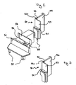
- FIG 2 a perspective view of an end cap 5 is shown.
- the end cap 5 has holding elements 55 on its underside, which are designed in such a way that they engage in the hollow chamber of a profile strip, not shown here.
- the contour of the end cap 5 is designed in such a way that it is equipped with an outer circumference at least partially axially adjoining the profile strip (not shown).
- the end cap 5 can completely cover the free end and thus the hollow chamber of a profile strip, not shown, in a sealing manner.
- the end cap 5 has a functional element 50 which is made from a flexible thermoplastic elastomer.
- the functional element 50 has an approximately prismatic base 51 on which a sealing element 53 and a tolerance compensation element 52 are arranged in one piece.
- the tolerance compensation element 52 has an approximately U-shaped recess 520 formed over its entire length and is non-positively connected to the positioning element 56 .
- the base 51 is approximately rectangular and is connected to the end cap 5 in a materially bonded manner, for example by means of an adhesive.
- the base 51 can be fixed to the end cap 5 by means of hooks, snap-in or plug-in connections known per se.
- the end cap 5 used according to the invention also has a positioning element 56, which in this exemplary embodiment is arranged approximately at right angles to the functional element 50 and has an angled portion arranged approximately parallel to the sealing element 53 of the functional element 50, which in the installed state (see Fig. figure 1 ), Sealing the free end of the casement 2, supporting it, engages behind.
- a positioning element 56 which in this exemplary embodiment is arranged approximately at right angles to the functional element 50 and has an angled portion arranged approximately parallel to the sealing element 53 of the functional element 50, which in the installed state (see Fig. figure 1 ), Sealing the free end of the casement 2, supporting it, engages behind.
- the end cap 5 used according to the invention has an opening 54 through which the end cap 5 can be mechanically connected to the profile strip (not shown).
- the opening 54 of the end cap 5 lies between the ribs 57, 58 projecting approximately at right angles from the upper side of the end cap 5.
- the ribs 57, 58 of the end cap 5 are designed in such a way that their opposite free ends have a bevel or a radius, so that in the assembled state (see figure 1 )
- the seals 11, 12 of the frame 1 can create a seal on the rib 57, 58.
- the functional element 50 is produced in one piece with the end cap 5, for example using the two-component injection molding process known per se.
- the end cap 5 it is also within the scope of the invention for the end cap 5 to be designed in several parts, so that it is divided, for example, at the rib 57 and/or at the rib 58 in a non-positive manner, and thus the end cap 5 can also be used for faceplate profiles of different geometries by separating individual elements is usable.
- FIG 3 a section of a perspective view of the end cap 5 is shown.
- the functional element 50 which consists of a base 51 , a sealing element 53 and a tolerance compensation element 52 , is arranged on the positioning element 56 of the end cap 5 .
- the base 51 is non-positively connected to the upper side of the end cap 5 visible underneath, by a foot, not shown here, which can be inserted into the hollow chamber of the end cap 5, also not shown.
- the sealing element 53 has a wall thickness of 0.6 mm and is made of a flexible material with a Shore A hardness of 73.
- the flexible material was selected from the group of plasticized polyvinyl chlorides.
- the tolerance compensation element 52 is materially connected to the base 51 of the functional element 50 and to the positioning element 56 .
- the end cap 5 was made from a material that can be processed thermoplastically, preferably from acrylonitrile-styrene-acrylic ester copolymer (ASA), to which the functional element 50, preferably made from soft polyvinyl chloride, was attached in a force-fitting manner via the base 51 and via the Tolerance compensation element 52 cohesively on the positioning element 56 of End cap 5 is fixed.
- ASA acrylonitrile-styrene-acrylic ester copolymer
- the tolerance compensation element 52 has an approximately V-shaped recess 520 which extends over the entire longitudinal axis of the tolerance compensation element 52 .
- the sealing element 53 of the functional element 50 has a different geometry which, when used in windows, doors and the like, also brings about tolerance compensation in addition to the sealing effect.
- the functional element 50 can also be designed in such a way that the base 51 and/or the sealing element 53 has additional ribs, knobs, lamellae and the like, which further enhance the effect of the end cap 5 and the functional element 50 .
- the choice of materials means that both the base 51 and the sealing element 53 and the tolerance compensation element 52 can be correspondingly flexible and cost-effectively adapted to the tightness and tolerance compensation requirements for windows, doors and the like.
- functional element 50 it is also within the scope of the invention for functional element 50 to be designed in such a way that another sealing element, which projects away from sealing element 53 and corresponds to the geometry of seals 21 , 31 of the casement 2, 3 is simulated.
- the sealing element 53 has at its free end opposite the base 51 a further sealing element pointing across its entire width and arranged approximately at an acute angle.
- the functional element 50 is designed in such a way that the sealing element 53 , which is connected in one piece to the base 51 , is arranged directly on the positioning element 56 .
- the sealing element 53 it is necessary, for example, for the sealing element 53 to have an additional sealing element at its free end opposite the base 51, which is adapted to the geometry of the seals 21, 31 (not shown here) of the casement 2, 3 .
Landscapes
- Engineering & Computer Science (AREA)
- Civil Engineering (AREA)
- Structural Engineering (AREA)
- Specific Sealing Or Ventilating Devices For Doors And Windows (AREA)
Description
Die Erfindung betrifft die Verwendung einer Endkappe zum Verschließen einer Hohlkammer eines Blindpfosten, eines Stulpprofils oder eines Sprossenprofils eines Fensters, einer Tür und dergleichen gemäß dem Obergriff des Anspruches 1.The invention relates to the use of an end cap for closing a hollow chamber of a blind post, a forend profile or a transom profile of a window, a door and the like according to the preamble of claim 1.
Derartige Endkappen werden im Stand der Technik dazu eingesetzt, die Hohlkammern von Profilleisten eines Fensters, einer Tür und dergleichen zu verschließen. Diese Profilleisten werden eingesetzt im Fensterbau beispielweise bei mehrflügeligen Fenstern zwischen denen ein Blindpfosten, ein Stulpprofil, ein Sprossenprofil und dgl. angeordnet ist. Die Fenster, Türen und dergleichen weisen im Allgemeinen einen rechteckigen Querschnitt auf, wobei das Fenster bzw. die Tür bildenden Profilleisten an ihren freien Enden miteinander stoffschlüssig verbunden sind. Die zwischen den Fenster-, Türflügel und dergleichen eingesetzten Profilleisten wie Blindpfosten, ein Stulpprofil, ein Sprossenprofil und dgl. sind an ihren freien Enden offen, so dass in die Hohlkammern dieser Profilleisten Schmutz bzw. Flüssigkeiten eindringen können.Such end caps are used in the prior art to close the hollow chambers of profile strips of a window, a door and the like. These profile strips are used in window construction, for example in the case of multi-leaf windows between which a blind post, a mullion profile, a sash bar profile and the like is arranged. The windows, doors and the like generally have a rectangular cross section, with the profile strips forming the window or the door being bonded to one another at their free ends. The profile strips used between the window, door leaf and the like, such as blind posts, a faceplate profile, a rung profile and the like. Are open at their free ends, so that dirt or liquids can penetrate into the hollow chambers of these profile strips.
Um dies zu verhindern, werden sogenannte Endkappen verwendet, die in die Hohlkammern der Profilleiste eingreifende Halteelemente aufweisen und einem an die Profilleiste axial anschließenden Außenumfang, so dass die freien Enden dieser Profilleisten abdichtend und optisch ansprechend abgeschlossen sind.To prevent this, so-called end caps are used, which have retaining elements engaging in the hollow chambers of the profile strip and an outer circumference axially adjoining the profile strip, so that the free ends of these profile strips are sealed off and optically appealing.
Eine derartige Endkappe ist beispielsweise in der
Diese Endkappe soll optische Mängel beseitigen, wenn verschiedenfarbige Hohlprofilstäbe zu einem Fenster, zu einer Tür und dergleichen zusammengebaut sind.This end cap is intended to eliminate optical defects when differently colored hollow profile rods are assembled into a window, a door and the like.
Nachteilig bei dieser Endkappe wird gesehen, dass beispielsweise durch die Toleranzen zwischen den beiden separaten Teilstücken sowohl die Dichtwirkung als auch der Toleranzausgleich zwischen den verschiedenen ein Fenster, eine Tür und dergleichen bildenden Profilleisten erheblich erschwert ist.The disadvantage of this end cap is that, for example, due to the tolerances between the two separate sections, both the sealing effect and the tolerance compensation between the various profile strips forming a window, a door and the like are made considerably more difficult.
Ein weiterer Nachteil der Endkappe wird darin gesehen, dass durch die Mehrteiligkeit insbesondere bei einer Endkappe aus einem metallischen aber auch einem thermoplastischen Werkstoff kein Toleranzausgleich zwischen den die Fenster, Türen und dergleichen bilden-den Profilleisten erreichbar ist und das insbesondere bei diesen Materialien eine normgerechte Abdichtung insbesondere im Bereich der äußeren Dichtungsebene der Fenster, Türen und dergleichen nicht möglich ist.A further disadvantage of the end cap is seen in the fact that due to the multi-piece design, particularly in the case of an end cap made of a metallic or also a thermoplastic material, no tolerance compensation can be achieved between the profile strips forming the windows, doors and the like, and that, in particular with these materials, a standard-compliant seal especially in the area of the outer sealing level of the windows, doors and the like is not possible.
Hier setzt die Erfindung ein, die sich die Aufgabe gestellt hat, die Nachteile des bekannten Standes der Technik zu überwinden und eine Endkappe aufzuzeigen, die wirtschaftlich und kostengünstig herstellbar ist, die bei ausreichender mechanischer Festigkeit und Stabilität eine normgerechte Abdichtung sowie zusätzlich einen Toleranzausgleich ermöglicht.This is where the invention comes in, which has set itself the task of overcoming the disadvantages of the known prior art and demonstrating an end cap which can be produced economically and inexpensively, which, with sufficient mechanical strength and stability, enables standard-compliant sealing and additional tolerance compensation.
Die Aufgabe der Erfindung wird durch die Merkmale des Anspruches 1 gelöst.The object of the invention is achieved by the features of claim 1.
Weitere vorteilhafte Ausgestaltungen sind in den Unteransprüchen beschrieben.Further advantageous configurations are described in the dependent claims.
Es konnte festgestellt werden, dass eine Endkappe zum Verschließen einer Hohlkammer eines Blindpfosten, eines Stulpprofils oder eines Sprossenprofils eines Fensters, einer Tür und dergleichen, mit in die Hohlkammer eingreifenden Halteelementen, mit einem an die Profilleiste wenigstens teilweise axial anschließendem Außenumfang vorteilhafterweise wenigstens ein Funktionselement aufweist, welches wenigstens teilweise aus einem weichelastischen Werkstoff besteht. Dieses Funktionselement ist so ausgebildet, dass der zwischen der Profilleiste beispielsweise einem Stulpprofil zum Blendrahmen bzw. zum Flügelrahmen bestehende Spalt abgedichtet ist und gleichzeitig mögliche fertigungsbedingte Toleranzen ausgeglichen werden können.It was found that an end cap for closing a hollow chamber of a blind post, a forend profile or a glazing bar profile of a window, a door and the like, with retaining elements engaging in the hollow chamber, with an outer circumference at least partially axially adjoining the profile strip, advantageously has at least one functional element , which consists at least partially of a flexible material. This functional element is designed in such a way that the gap existing between the profile strip, for example a faceplate profile, to the window frame or to the casement frame is sealed and at the same time possible production-related tolerances can be compensated for.
Dabei ist der weichelastische Werkstoff des Funktionselementes ausgewählt aus der Gruppe der Thermoplaste, der Duromere, der Silikone, der Elastomere, Gummi und dergleichen, was eine kostengünstige Herstellung der Endkappe ermöglicht.The flexible material of the functional element is selected from the group of thermoplastics, duromers, silicones, elastomers, rubber and the like, which allows the end cap to be produced cost-effectively.
Der weichelastische Werkstoff des Funktionselementes kann vorteilhafterweise ausgewählt sein aus der Gruppe der thermoplastischen Elastomere, der thermoplastischen Copolyester, der Styrol-Blockcopolymere, der thermoplastische Copolyamide, der Polyurethane, weichmacherhaltigen Polyvinylchloride und dergleichen.The flexible material of the functional element can advantageously be selected from the group of thermoplastic elastomers, thermoplastic copolyesters, styrene block copolymers, thermoplastic copolyamides, polyurethanes, plasticized polyvinyl chloride and the like.
Dabei ist das Funktionselement beispielsweise stoffschlüssig mit der Endkappe verbunden, was die Herstellungskosten reduziert und die Geometrievielfalt dieser Endkappen gleichzeitig erhöht.In this case, the functional element is, for example, materially connected to the end cap, which reduces the production costs and at the same time increases the variety of geometries of these end caps.
Es liegt jedoch auch im Rahmen der Erfindung, dass das Funktionselement kraftschlüssig mit der Endkappe verbunden ist, sodass verschiedene Farbvarianten beispielsweise der Endkappe bzw. des Funktionselementes miteinander kombinierbar sind. Weiterhin ist es durch diese vorteilhafte Ausgestaltung möglich, bereits montierte Endkappen in Fenstern bzw. Türen durch die erfindungsgemäß verwendete Endkappe zu ersetzen bzw. durch das Funktionselement zu sanieren.However, it is also within the scope of the invention for the functional element to be non-positively connected to the end cap, so that different color variants, for example of the end cap or of the functional element, can be combined with one another. Furthermore, this advantageous embodiment makes it possible to replace already mounted end caps in windows or doors with the end cap used according to the invention or to renovate them with the functional element.
Ein weiterer Vorteil der erfindungsgemäßen Verwendung wird darin gesehen, dass das Funktionselement wenigstens teilweise aus einem weichelastischen Werkstoff besteht. Dabei sind vor allem solche Werkstoffe vorteilhaft einsetzbar, die eine Härte von maximal Shore A 96 aufweisen.A further advantage of the use according to the invention is seen in the fact that the functional element consists at least partially of a flexible material. Materials that can be used advantageously have a maximum hardness of Shore A 96.
Es liegt jedoch auch im Rahmen der Erfindung, dass der weichelastische Werkstoff ausgewählt ist aus der Gruppe der geschäumten und/oder schäumbaren Werkstoffe, die eine Dichte von maximal 0,5 g/cm3 aufweisen.However, it is also within the scope of the invention for the flexible material to be selected from the group of foamed and/or foamable materials Materials that have a maximum density of 0.5 g/cm 3 .
In einer weiteren vorteilhaften Ausgestaltung der erfindungsgemäßen Verwendung weist das Funktionselement eine Wandstärke von etwa 0,2 bis 5 mm, vorzugsweise 0,5 bis 1,5 mm auf.In a further advantageous embodiment of the use according to the invention, the functional element has a wall thickness of approximately 0.2 to 5 mm, preferably 0.5 to 1.5 mm.
Durch diese Ausgestaltung sind Endkappen herstellbar, die das bekannte Problem der Dichtigkeit und des Toleranzausgleiches, insbesondere bei Profilleisten, die als Stulpprofile und dergleichen ausgebildet sind, lösen.With this configuration, end caps can be produced that solve the well-known problem of tightness and tolerance compensation, particularly in the case of profile strips that are designed as cuff profiles and the like.
Erfindungsgemäß zeichnet sich die Verwendung dadurch aus, dass das Funktionselement wenigstens eine Basis und wenigstens ein Toleranzausgleichselement aufweist. Hierdurch ist es möglich, in verschiedenen komplizierten Geometrien von Stulpprofilen, Blendrahmenprofilen bzw. Flügelrahmenprofilen eine Endkappe zur Verfügung zu stellen, die in den kritischen Bereichen sowohl eine abdichtende Wirkung aufweist, als auch zusätzlich einen Toleranzausgleich zwischen den einzelnen Profilen bewirkt.According to the invention, the use is characterized in that the functional element has at least one base and at least one tolerance compensation element. This makes it possible to provide an end cap in various complicated geometries of cuff profiles, blind frame profiles or casement profiles that has both a sealing effect in the critical areas and also causes tolerance compensation between the individual profiles.
Dabei kann in einer weiteren vorteilhaften Ausgestaltung das Dichtelement stoffschlüssig und/oder kraftschlüssig mit der Basis und/oder mit der Endkappe verbunden sein, was eine vielfältige Anzahl von Herstellungsmöglichkeiten offen lässt, ohne die Funktionalität der erfindungsgemäß verwendeten Endkappe einzuschränken.In a further advantageous embodiment, the sealing element can be connected to the base and/or to the end cap in a materially bonded and/or non-positive manner, which leaves a wide range of manufacturing options open without restricting the functionality of the end cap used according to the invention.
Erfindungsgemäß ist das Toleranzausgleichselement bezogen auf seine Längsachse flexibel ausgebildet. Durch diese vorteilhafte Geometrie ist das Toleranzausgleichselement in der Lage, im eingebauten Zustand auftretende Druckkräfte im Fenstersystem, beispielsweise durch öffnen bzw. Schließen eines Flügelrahmens trotz bestehender Fertigungstoleranzen, aufzunehmen und so das Fenstersystem abzudichten. Dabei kann das Toleranzausgleichselement der erfindungsgemäß verwendeten Endkappe über seine Längsachse aufgrund der weichelastischen Werkstoffe flexibel die Toleranzunterschiede der Profilleisten eines Fenstersystems ausgleichen.According to the invention, the tolerance compensation element is designed to be flexible in relation to its longitudinal axis. Due to this advantageous geometry, the tolerance compensation element is able to absorb compressive forces occurring in the window system in the installed state, for example due to opening or closing of a casement despite existing manufacturing tolerances, and thus to seal the window system. The tolerance compensation element of the end cap used according to the invention can flexibly compensate the tolerance differences of the profile strips of a window system via its longitudinal axis due to the flexible materials.
Das Toleranzausgleichselement ist weiterhin im Querschnitt etwa U-förmig, C-förmig, Z-förmig und dergleichen ausgebildet ist. Die Geometrie des Toleranzausgleichselementes kann somit entsprechend der Geometrie des Blindpfostens, des Stulpprofils, des Sprossenprofils und dergleichen so angepasst werden, dass alle fertigungsbedingten Toleranzen abdichtend ausgleichbar sind.The tolerance compensating element is also designed with an approximately U-shaped, C-shaped, Z-shaped and the like cross-section. The geometry of the tolerance compensation element can thus be adapted according to the geometry of the dummy post, the faceplate profile, the rung profile and the like so that all production-related tolerances can be compensated for in a sealing manner.
Entsprechend den Anforderungen der Fenstersysteme kann der Werkstoff des Toleranzausgleichselementes im Querschnitt eine zell- und/oder wabenförmige Struktur aufweisen, insbesondere bei der Verwendung von geschäumten und/oder schäumbaren Werkstoffen.According to the requirements of the window systems, the material of the tolerance compensation element can have a cellular and/or honeycomb structure in cross section, particularly when using foamed and/or foamable materials.
In der erfindungsgemäß verwendeten Endkappe weist das Toleranzausgleichselement wenigstens eine Ausnehmung, eine Hohlkammer und dergleichen auf, die so ausgebildet ist, dass bei normgerechtem Einsatz der erfindungsgemäß verwendeten Endkappe fertigungsbedingte Toleranzen insbesondere der Blendrahmen- bzw. Flügelrahmenprofile abdichtend ausgeglichen werden, ohne dass diese abdichtende und toleranzausgleichende Wirkung im Laufe der Zeit durch mechanische Beanspruchung bzw. Werkstoffveränderungen zu Undichtigkeiten an den Fenstern, Türen und dergleichen führt.In the end cap used according to the invention, the tolerance compensation element has at least one recess, a hollow chamber and the like, which is designed in such a way that when the end cap used according to the invention is used in accordance with standards, production-related tolerances, in particular of the frame or casement profiles, are compensated for in a sealing manner without these sealing and tolerance-compensating Effect over time due to mechanical stress or material changes to leaks in the windows, doors and the like.
Die erfindungsgemäß verwendete Endkappe ist weiterhin vorteilhaft so ausgebildet, dass sie wenigstens eine Öffnung aufweist, durch die an sich bekannte Befestigungselemente einführbar sind, die die Endkappe abdichtend und dem Design der Profilleiste beispielsweise eines Stulpprofiles angepasst, dieses abdichtend, befestigbar ist.The end cap used according to the invention is also advantageously designed in such a way that it has at least one opening through which known fastening elements can be inserted which seal the end cap and are adapted to the design of the profile strip, for example a cuff profile, which can be sealed and fastened.
Dabei kann die Position der Öffnungen so gewählt sein, dass die abdichtende toleranzausgleichende Funktion der Endkappe und insbesondere des Funktionselementes noch zusätzlich durch eine gewisse Vorspannung unterstützbar ist.The position of the openings can be selected in such a way that the sealing, tolerance-compensating function of the end cap and in particular of the functional element can also be additionally supported by a certain pretension.
Die Erfindung soll nun an einem diese nicht einschränkenden Ausführungsbeispiel näher beschrieben werden. Es zeigen:
-
Figur 1 perspektivische Darstellung einer erfindungsgemäß verwendeten Endkappe an einem Fenstersystem -
Figur 2 -
Figur 3
-
figure 1 perspective view of an end cap used according to the invention on a window system -
figure 2 perspective view of an end cap for use according to the invention -
figure 3 perspective view of the section of the end cap for use according to the invention
In
Das Fenstersystem weist einen weiteren Flügelrahmen 3 auf, der ebenfalls ein Dichtelement 31 aufweist. Zwischen dem Flügelrahmen 2 und dem Flügelrahmen 3 ist eine Profilleiste 4 angeordnet, welche in diesem Ausführungsbeispiel als Stulpprofil ausgebildet ist. An einem freien Ende der Profilleiste 4 ist eine Endkappe 5 angeordnet, die die Hohlkammer der Profilleiste 4 abdeckt und in die Hohlkammer eingreifende, hier nicht dargestellte, Halteelemente 55 aufweist, wobei die Endkappe 5 so ausgebildet ist, dass sie mit einem an die Profileiste 4 axial anschließenden Außenumfang ausgestattet ist, der zumindest teilweise der Kontur der Profilleiste 4 entspricht.The window system has a
Zur besseren Darstellung wurde der dem Blendrahmen 1 gegenüberliegende Blendrahmen, welcher mit dem Flügelrahmen 3 in Wirkverbindung steht, nicht dargestellt.For the sake of clarity, the blind frame opposite the blind frame 1, which is in operative connection with the
Die auf der Profilleiste 4 angeordnete Endkappe 5 weist ein Funktionselement 50 auf, welches an den Dichtungen 21, 31 der Flügelrahmen 2, 3 angeordnet ist.The arranged on the
In dem Spalt 6 zwischen dem Flügelrahmen 2 und dem Flügelrahmen 3 ist ein Positionierelement 56 angeordnet, welches das freie Ende des Flügelrahmens 2 abdichtet.A
Das Funktionselement 50 der Endkappe 5 verbindet somit die Dichtungen 21, 31 der Flügelrahmen 2, 3, sodass zwischen dem Flügelrahmen 2 und dem Flügelrahmen 3 eindringende Feuchtigkeit bzw. Schmutz nicht über das Dichtelement 53 auf die Rauminnenseite gelangen kann.The
Eine weitere Abdichtung des Flügelrahmens 2, 3 wird durch die, hier nicht dargestellten, senkrechten Dichtungen der Profilleiste 4 realisiert.A further sealing of the
Die Endkappe 5 ist in diesem Ausführungsbeispiel so ausgebildet, dass eine Rippe 58 eine direkte Verbindung zwischen den Flügelrahmen 2, 3 dahingehend ermöglicht, dass eine im Blendrahmen 1 angeordnete Dichtung 11 welche am Flügelrahmen 2,3 anliegt, den Spalt zwischen dem Flügelrahmen 2, 3 abdichtend überbrückt. Zur weiteren Verbesserung der Dichtwirkung und zur Schaffung einer so genannten dritten Dichtungsebene ist an der Endkappe 5 eine Rippe 57 angeordnet, die ebenfalls an den Innenseiten des Flügelrahmens 2, 3 so angeordnet ist, dass eine Dichtung 12 des Blendrahmens 1 den Spalt zwischen dem Flügelrahmen 2 und dem Flügelrahmen 3 abdichtend überbrückt.In this exemplary embodiment, the
In
Die Kontur der Endkappe 5 ist so ausgebildet, dass sie mit einem, an die nicht dargestellte Profilleiste, wenigstens teilweise axial anschließenden Außenumfang ausgestattet ist. Somit kann die Endkappe 5 das freie Ende und damit die Hohlkammer einer nicht dargestellten Profilleiste vollumfänglich abdichtend überdecken.The contour of the
In diesem Ausführungsbeispiel weist die Endkappe 5 ein Funktionselement 50 auf, welches aus einem weichelastischen thermoplastischen Elastomer hergestellt ist. Das Funktionselement 50 weist eine etwa prismatisch ausgebildete Basis 51 auf, an der ein Dichtelement 53 und ein Toleranzausgleichselement 52 einstückig angeordnet sind.In this exemplary embodiment, the
Das Toleranzausgleichselement 52 weist in diesem Beispiel eine etwa U-förmige über seine gesamte Länge ausgebildete Ausnehmung 520 auf und ist kraftschlüssig mit dem Positionierelement 56 verbunden ist.In this example, the
Die Basis 51 ist in dieser Ausführungsform etwa rechteckig ausbildet und über bspw. Klebstoff stoffschlüssig mit der Endkappe 5 verbunden.In this embodiment, the
Es liegt jedoch auch im Rahmen der Erfindung, dass die Basis 51 über an sich bekannte Haken, Rast- bzw. Steckverbindungen mit der Endkappe 5 fixierbar ist.However, it is also within the scope of the invention that the base 51 can be fixed to the
Die erfindungsgemäß verwendete Endkappe 5 weist weiterhin ein Positionierelement 56 auf, welches in diesem Ausführungsbeispiel etwa rechtwinklig zum Funktionselement 50 angeordnet ist und eine etwa parallel zum Dichtelement 53 des Funktionselements 50 angeordnete Abwinklung aufweist, die im eingebauten Zustand (sh.
Die erfindungsgemäß verwendete Endkappe 5 weist in diesem Ausführungsbeispiel eine Öffnung 54 auf, durch die die Endkappe 5 mit der nicht dargestellten Profilleiste mechanisch verbindbar ist. Die Öffnung 54 der Endkappe 5 liegt zwischen den etwa rechtwinklig von der Oberseite der Endkappe 5 wegragenden Rippen 57, 58.In this exemplary embodiment, the
Die Rippen 57, 58 der Endkappe 5 sind in diesem Ausführungsbeispiel so ausgebildet, dass ihre einander gegenüberliegenden freien Enden eine Abschrägung bzw. einen Radius aufweisen, so dass im montierten Zustand (sh.
Das Funktionselement 50 ist in diesem Ausführungsbeispiel einstückig mit der Endkappe 5 hergestellt, beispielsweise im an sich bekannten Zweikomponenten-Spritzgießverfahren.In this exemplary embodiment, the
Es liegt jedoch auch im Rahmen der Erfindung, dass die Endkappe 5 mehrteilig ausgebildet ist, sodass diese beispielsweise an der Rippe 57 und/oder an der Rippe 58 kraftschlüssig geteilt, hergestellt ist und somit die Endkappe 5 auch für Stulpprofile unterschiedlicher Geometrien durch Abtrennen einzelner Elemente verwendbar ist.However, it is also within the scope of the invention for the
In
Die Basis 51 ist kraftschlüssig mit der darunter sichtbaren Oberseite der Endkappe 5 verbunden, durch einen hier nicht dargestellten Fuß, der in die ebenfalls nicht dargestellte Hohlkammer der Endkappe 5 einführbar ist.The
Das Dichtelement 53 weist in diesem Ausführungsbeispiel eine Wandstärke von 0,6 mm auf und ist aus einem weichelastischen Werkstoff mit einer Härte Shore A 73 ausgebildet. Der weichelastische Werkstoff wurde ausgewählt aus Gruppe der weichmacherhaltigen Polyvinylchloride.In this exemplary embodiment, the sealing
Das Toleranzausgleichselement 52 ist stoffschlüssig mit der Basis 51 des Funktionselementes 50 und mit dem Positionierelement 56 verbunden.The
In diesem Ausführungsbeispiel wurde die Endkappe 5 aus einem thermoplastisch verarbeitbaren Werkstoff, vorzugsweise aus Acrylnitril-Styrol-Acrylester-Copolymer (ASA) hergestellt, an die in einem separaten Arbeitsgang das Funktionselement 50 vorzugsweise aus weich-Polyvinylchlorid über die Basis 51 kraftschlüssig angefügt und über das Toleranzausgleichselement 52 stoffschlüssig am Positionierelement 56 der Endkappe 5 fixiert ist. Das Toleranzausgleichselement 52 weist in diesem Ausführungsbeispiel eine etwa V-förmige Ausnehmung 520 auf, die sich über die gesamte Längsachse des Toleranzausgleichselementes 52 erstreckt.In this exemplary embodiment, the
Durch diese Ausbildung ist das Funktionselement 50, welches über das Dichtelement 53 abdichtend mit den hier nicht dargestellten Dichtungen 21, 31 der Flügelrahmen 2, 3 in Wirkverbindung steht, gleichzeitig toleranzausgleichend zum Blendrahmen 1 sowie zur Profilleiste 4, da über die Ausnehmung 520 bei gleichbleibender Dichtwirkung eine gewisse Verformung bzw. Flexibilität des Funktionselementes 50 möglich ist.This design means that
Es liegt jedoch auch im Rahmen der Erfindung, dass beispielsweise das Dichtelement 53 des Funktionselementes 50 eine andere Geometrie aufweist, die beim Einsatz in Fenstern, Türen und dergleichen neben der abdichtenden Wirkung auch einen Toleranzausgleich bewirkt.However, it is also within the scope of the invention that, for example, the sealing
Das Funktionselement 50 kann dabei weiterhin so ausgebildet sein, dass die Basis 51 und/oder das Dichtelement 53 zusätzliche Rippen, Noppen, Lamellen und dergleichen aufweist, die die Wirkung der Endkappe 5 und des Funktionselementes 50 noch verstärken. Dabei können durch die Wahl der Werkstoffe sowohl die Basis 51 als auch das Dichtelement 53 sowie das Toleranzausgleichselement 52 entsprechend flexibel und den Anforderungen an die Dichtigkeit und den Toleranzausgleich bei Fenstern, Türen und dergleichen kostengünstig angepasst werden.The
Es liegt auch im Rahmen der Erfindung, dass das Funktionselement 50 so ausgebildet ist, dass an dem die Basis 51 und das Toleranzausgleichselement 52 verbindenden Dichtelement 53 ein weiteres, vom Dichtelement 53 wegragendes, Dichtelement angeordnet ist, welches der Geometrie der hier nicht dargestellten Dichtungen 21, 31 der Flügelrahmen 2, 3 nachgebildet ist. Dabei weist das Dichtelement 53 an seinem der Basis 51 gegenüberliegenden freien Ende ein über seine gesamte Breite weisendes, etwa in einem spitzen Winkel angeordnetes weiteres Dichtelement auf.It is also within the scope of the invention for
Es liegt weiterhin im Rahmen der Erfindung, dass das Funktionselement 50 so ausgebildet ist, dass das Dichtelement 53, welches einstückig mit der Basis 51 verbunden ist, direkt am Positionierelement 56 angeordnet ist.It is also within the scope of the invention that the
In dieser vorteilhaften Ausgestaltung des Funktionselementes 50 ist es bspw. erforderlich, dass das Dichtelement 53 an seinem, der Basis 51 gegenüberliegenden freien Ende, ein zusätzliches Dichtelement aufweist, welches der Geometrie der hier nicht dargestellten Dichtungen 21, 31 des Flügelrahmens 2, 3 nachgebildet ist. In this advantageous embodiment of the
Claims (9)
- Use of an end cap (5) for closing a hollow chamber of a mullion, a meeting profile or a glazing bar profile of a window, door and the like, having retaining elements (55) which engage in the hollow chamber, having an outer perimeter at least partially axially adjacent to the profile strip (4), wherein the end cap (5) has at least one functional element (50) that consists at least in part of a soft elastic material, wherein the functional element (50) has a base (51) and at least one tolerance compensating element (52), the tolerance compensating element (52) being designed to be flexible with respect to its longitudinal axis,
characterised in that
the tolerance compensating element (52) has at least one recess (520) or hollow chamber. - Use according to claim 1, characterised in that the soft elastic material of the functional element (50) is chosen from the group of thermoplastic materials, thermoset materials, silicones, elastomers, rubber and the like.
- Use according to claim 1 and 2, characterised in that the soft elastic material of the functional element (50) is chosen from the group of thermoplastic elastomers, thermoplastic copolyesters, styrene block copolymers, thermoplastic copolyamides, polyurethanes, plasticiser-containing polyvinyl chloride and the like.
- Use according to one of the preceding claims, characterised in that the functional element (50) is connected to the end cap (5) in material integral manner.
- Use according to one of the preceding claims, characterised in that the functional element (50) is connected to the end cap (5) in force fitting manner.
- Use according to one of the preceding claims, characterised in that the functional element (50) has a wall thickness of approximately 0.2 to 5 mm, preferably 0.5 to 1.5 mm.
- Use according to claim 1, characterised in that the tolerance compensating element (52) is connected to the base (51) and/or to the end cap (5) in material integral manner and/or in force fitting manner.
- Use according to one of the preceding claims, characterised in that the tolerance compensating element (52) is approximately U-shaped, C-shaped, Z-shaped or the like in cross section.
- Use according to one of the preceding claims, characterised in that the tolerance compensating element (52) has a cellular and/or honeycomb structure in cross section.
Applications Claiming Priority (2)
| Application Number | Priority Date | Filing Date | Title |
|---|---|---|---|
| DE202008003931U DE202008003931U1 (en) | 2008-03-20 | 2008-03-20 | endcap |
| PCT/EP2009/001887 WO2009115256A1 (en) | 2008-03-20 | 2009-03-16 | End cap |
Publications (3)
| Publication Number | Publication Date |
|---|---|
| EP2274493A1 EP2274493A1 (en) | 2011-01-19 |
| EP2274493B1 EP2274493B1 (en) | 2014-09-03 |
| EP2274493B2 true EP2274493B2 (en) | 2022-07-13 |
Family
ID=40800484
Family Applications (1)
| Application Number | Title | Priority Date | Filing Date |
|---|---|---|---|
| EP09722069.3A Active EP2274493B2 (en) | 2008-03-20 | 2009-03-16 | End cap |
Country Status (3)
| Country | Link |
|---|---|
| EP (1) | EP2274493B2 (en) |
| DE (1) | DE202008003931U1 (en) |
| WO (1) | WO2009115256A1 (en) |
Families Citing this family (5)
| Publication number | Priority date | Publication date | Assignee | Title |
|---|---|---|---|---|
| ITMC20090257A1 (en) * | 2009-12-23 | 2011-06-24 | Alessandro Cirilli | STOPPER FOR WINDOWS. |
| EP2503089A1 (en) | 2011-03-24 | 2012-09-26 | profine GmbH | System for producing a double leaf window and mullion cap for same |
| DE102017100293A1 (en) | 2016-01-08 | 2017-07-13 | Profine Gmbh | End cap and its use |
| EP3190255B1 (en) | 2016-01-08 | 2019-04-03 | Profine GmbH | End cap and its use |
| DE102018101765B4 (en) | 2018-01-26 | 2019-12-05 | Stahl Cranesystems Gmbh | Scalable hysteresis clutch |
Citations (2)
| Publication number | Priority date | Publication date | Assignee | Title |
|---|---|---|---|---|
| DE8221853U1 (en) † | 1982-08-02 | 1982-11-25 | Gebrüder Kömmerling Kunststoffwerke GmbH, 6780 Pirmasens | SINGLE-WING WINDOW |
| DE19615378A1 (en) † | 1996-04-18 | 1997-10-23 | Koemmerling Kunststoff | Sealing body for window or door profiles |
Family Cites Families (8)
| Publication number | Priority date | Publication date | Assignee | Title |
|---|---|---|---|---|
| NL156478B (en) * | 1975-02-13 | 1978-04-17 | Kateka Bv | WINDOW CONSTRUCTION. |
| DE7623292U1 (en) * | 1976-07-23 | 1976-12-09 | Schueco Heinz Schuermann Gmbh & Co, 4800 Bielefeld | WINDOW OR DOOR IN FRONT LEAF DESIGN |
| DE8318000U1 (en) * | 1983-06-22 | 1983-10-20 | Fa. Carl Freudenberg, 6940 Weinheim | KIT FOR SEALING CONNECTION AND SPACING AT LEAST TWO GLASS PANELS |
| DE9102714U1 (en) | 1991-03-07 | 1991-06-06 | Niemann, Hans Dieter, 5014 Kerpen | End cap for closing a hollow profile bar of windows, doors, etc. |
| DE9401256U1 (en) * | 1994-01-26 | 1994-03-10 | Grotefeld, Hans Dieter, 32549 Bad Oeynhausen | Fighter connector |
| DE29620153U1 (en) * | 1996-11-20 | 1998-03-19 | Niemann, Hans Dieter, 50169 Kerpen | Connection for angled hollow profile bars |
| DE19800130C1 (en) * | 1998-01-03 | 1999-05-20 | Hans Dieter Grotefeld | Connector for window or door frames |
| EP1035294B1 (en) * | 1999-03-05 | 2004-07-07 | Hans Dieter Grotefeld | Assembly kit for a mullion within a frame |
-
2008
- 2008-03-20 DE DE202008003931U patent/DE202008003931U1/en not_active Expired - Lifetime
-
2009
- 2009-03-16 WO PCT/EP2009/001887 patent/WO2009115256A1/en active Application Filing
- 2009-03-16 EP EP09722069.3A patent/EP2274493B2/en active Active
Patent Citations (2)
| Publication number | Priority date | Publication date | Assignee | Title |
|---|---|---|---|---|
| DE8221853U1 (en) † | 1982-08-02 | 1982-11-25 | Gebrüder Kömmerling Kunststoffwerke GmbH, 6780 Pirmasens | SINGLE-WING WINDOW |
| DE19615378A1 (en) † | 1996-04-18 | 1997-10-23 | Koemmerling Kunststoff | Sealing body for window or door profiles |
Also Published As
| Publication number | Publication date |
|---|---|
| EP2274493A1 (en) | 2011-01-19 |
| WO2009115256A1 (en) | 2009-09-24 |
| DE202008003931U1 (en) | 2009-07-30 |
| EP2274493B1 (en) | 2014-09-03 |
Similar Documents
| Publication | Publication Date | Title |
|---|---|---|
| EP2921634B1 (en) | Seal for doors for sealing an air gap between a door wing on the one hand and a door frame, a floor, a ceiling, a lintel or the like on the other hand | |
| EP3221540B1 (en) | Sealing device for a slidable sash as a sliding shash or slidable lift-and-slide sash of a window or a door | |
| EP2824270B1 (en) | Surface element of a fire resistant glazing, in particular glass door for fire protection purposes for preventing fire and smoke passing between rooms in case of fire | |
| EP2274493B2 (en) | End cap | |
| DE102012010028A1 (en) | FRAME ARRANGEMENT FOR A SECTIONAL PANEL | |
| EP3034768A1 (en) | Window or door with a glazing rebate adhesive | |
| EP2476854B1 (en) | External cladding for a window, door or similar | |
| DE102014100369A1 (en) | Fire-resistant glazing with a wooden door | |
| EP2088337A2 (en) | Profile and profile system | |
| EP2363567A2 (en) | Frame of a plastic window or a plastic door as well as centre seal for it | |
| AT518200B1 (en) | Combi glass holder and thus equipped wood-aluminum composite window | |
| DE202008011056U1 (en) | Building window or building door and curb compensation part for use in a building window or a building door | |
| DE202017003552U1 (en) | Arrangement for securing inwardly opening windows and doors against burglary | |
| DE102005037926B4 (en) | Window arrangement for mobile rooms and retrofit kit for it | |
| DE60123854T2 (en) | Frame arrangement for glass or windows, fixed or mobile | |
| DE102009012202A1 (en) | Window i.e. double casement window, for building, has outer single glass pane and inner single glass pane forming steps, respectively, where step of inner single glass pane and step of outer single glass pane are not equal | |
| DE102010040498A1 (en) | Sealing arrangement for sealing portion of air gap region of door or window, has overlapping area-sealing element fixed at one of two wings of door | |
| EP2230373B1 (en) | Window cladding system for cladding a frame of a window | |
| DE102007002627B4 (en) | Multi-part profile for door frames and door leaves | |
| DE102007002640B4 (en) | Movable completion for an opening in a building | |
| DE102016111475A1 (en) | Seal insert for mounting in a frame | |
| DE202012100159U1 (en) | Window or door | |
| EP3075941B1 (en) | Building closure element | |
| WO2024211936A1 (en) | Profile for at least one cover element | |
| EP2823126A1 (en) | Window, door or the like, having a closure element |
Legal Events
| Date | Code | Title | Description |
|---|---|---|---|
| PUAI | Public reference made under article 153(3) epc to a published international application that has entered the european phase |
Free format text: ORIGINAL CODE: 0009012 |
|
| 17P | Request for examination filed |
Effective date: 20101008 |
|
| AK | Designated contracting states |
Kind code of ref document: A1 Designated state(s): AT BE BG CH CY CZ DE DK EE ES FI FR GB GR HR HU IE IS IT LI LT LU LV MC MK MT NL NO PL PT RO SE SI SK TR |
|
| AX | Request for extension of the european patent |
Extension state: AL BA RS |
|
| RAX | Requested extension states of the european patent have changed |
Extension state: RS Payment date: 20101008 |
|
| GRAP | Despatch of communication of intention to grant a patent |
Free format text: ORIGINAL CODE: EPIDOSNIGR1 |
|
| INTG | Intention to grant announced |
Effective date: 20140224 |
|
| GRAS | Grant fee paid |
Free format text: ORIGINAL CODE: EPIDOSNIGR3 |
|
| GRAP | Despatch of communication of intention to grant a patent |
Free format text: ORIGINAL CODE: EPIDOSNIGR1 |
|
| INTG | Intention to grant announced |
Effective date: 20140423 |
|
| GRAS | Grant fee paid |
Free format text: ORIGINAL CODE: EPIDOSNIGR3 |
|
| GRAA | (expected) grant |
Free format text: ORIGINAL CODE: 0009210 |
|
| STAA | Information on the status of an ep patent application or granted ep patent |
Free format text: STATUS: THE PATENT HAS BEEN GRANTED |
|
| AK | Designated contracting states |
Kind code of ref document: B1 Designated state(s): AT BE BG CH CY CZ DE DK EE ES FI FR GB GR HR HU IE IS IT LI LT LU LV MC MK MT NL NO PL PT RO SE SI SK TR |
|
| AX | Request for extension of the european patent |
Extension state: RS |
|
| REG | Reference to a national code |
Ref country code: GB Ref legal event code: FG4D Free format text: NOT ENGLISH |
|
| REG | Reference to a national code |
Ref country code: CH Ref legal event code: EP Ref country code: AT Ref legal event code: REF Ref document number: 685735 Country of ref document: AT Kind code of ref document: T Effective date: 20140915 |
|
| REG | Reference to a national code |
Ref country code: IE Ref legal event code: FG4D Free format text: LANGUAGE OF EP DOCUMENT: GERMAN |
|
| REG | Reference to a national code |
Ref country code: DE Ref legal event code: R096 Ref document number: 502009009892 Country of ref document: DE Effective date: 20141016 |
|
| PG25 | Lapsed in a contracting state [announced via postgrant information from national office to epo] |
Ref country code: LT Free format text: LAPSE BECAUSE OF FAILURE TO SUBMIT A TRANSLATION OF THE DESCRIPTION OR TO PAY THE FEE WITHIN THE PRESCRIBED TIME-LIMIT Effective date: 20140903 Ref country code: NO Free format text: LAPSE BECAUSE OF FAILURE TO SUBMIT A TRANSLATION OF THE DESCRIPTION OR TO PAY THE FEE WITHIN THE PRESCRIBED TIME-LIMIT Effective date: 20141203 Ref country code: GR Free format text: LAPSE BECAUSE OF FAILURE TO SUBMIT A TRANSLATION OF THE DESCRIPTION OR TO PAY THE FEE WITHIN THE PRESCRIBED TIME-LIMIT Effective date: 20141204 Ref country code: ES Free format text: LAPSE BECAUSE OF FAILURE TO SUBMIT A TRANSLATION OF THE DESCRIPTION OR TO PAY THE FEE WITHIN THE PRESCRIBED TIME-LIMIT Effective date: 20140903 Ref country code: SE Free format text: LAPSE BECAUSE OF FAILURE TO SUBMIT A TRANSLATION OF THE DESCRIPTION OR TO PAY THE FEE WITHIN THE PRESCRIBED TIME-LIMIT Effective date: 20140903 Ref country code: FI Free format text: LAPSE BECAUSE OF FAILURE TO SUBMIT A TRANSLATION OF THE DESCRIPTION OR TO PAY THE FEE WITHIN THE PRESCRIBED TIME-LIMIT Effective date: 20140903 |
|
| REG | Reference to a national code |
Ref country code: NL Ref legal event code: VDEP Effective date: 20140903 |
|
| REG | Reference to a national code |
Ref country code: LT Ref legal event code: MG4D |
|
| PG25 | Lapsed in a contracting state [announced via postgrant information from national office to epo] |
Ref country code: LV Free format text: LAPSE BECAUSE OF FAILURE TO SUBMIT A TRANSLATION OF THE DESCRIPTION OR TO PAY THE FEE WITHIN THE PRESCRIBED TIME-LIMIT Effective date: 20140903 Ref country code: HR Free format text: LAPSE BECAUSE OF FAILURE TO SUBMIT A TRANSLATION OF THE DESCRIPTION OR TO PAY THE FEE WITHIN THE PRESCRIBED TIME-LIMIT Effective date: 20140903 Ref country code: CY Free format text: LAPSE BECAUSE OF FAILURE TO SUBMIT A TRANSLATION OF THE DESCRIPTION OR TO PAY THE FEE WITHIN THE PRESCRIBED TIME-LIMIT Effective date: 20140903 |
|
| PG25 | Lapsed in a contracting state [announced via postgrant information from national office to epo] |
Ref country code: NL Free format text: LAPSE BECAUSE OF FAILURE TO SUBMIT A TRANSLATION OF THE DESCRIPTION OR TO PAY THE FEE WITHIN THE PRESCRIBED TIME-LIMIT Effective date: 20140903 |
|
| PG25 | Lapsed in a contracting state [announced via postgrant information from national office to epo] |
Ref country code: IS Free format text: LAPSE BECAUSE OF FAILURE TO SUBMIT A TRANSLATION OF THE DESCRIPTION OR TO PAY THE FEE WITHIN THE PRESCRIBED TIME-LIMIT Effective date: 20150103 Ref country code: RO Free format text: LAPSE BECAUSE OF FAILURE TO SUBMIT A TRANSLATION OF THE DESCRIPTION OR TO PAY THE FEE WITHIN THE PRESCRIBED TIME-LIMIT Effective date: 20140903 Ref country code: EE Free format text: LAPSE BECAUSE OF FAILURE TO SUBMIT A TRANSLATION OF THE DESCRIPTION OR TO PAY THE FEE WITHIN THE PRESCRIBED TIME-LIMIT Effective date: 20140903 Ref country code: CZ Free format text: LAPSE BECAUSE OF FAILURE TO SUBMIT A TRANSLATION OF THE DESCRIPTION OR TO PAY THE FEE WITHIN THE PRESCRIBED TIME-LIMIT Effective date: 20140903 Ref country code: PT Free format text: LAPSE BECAUSE OF FAILURE TO SUBMIT A TRANSLATION OF THE DESCRIPTION OR TO PAY THE FEE WITHIN THE PRESCRIBED TIME-LIMIT Effective date: 20150105 Ref country code: SK Free format text: LAPSE BECAUSE OF FAILURE TO SUBMIT A TRANSLATION OF THE DESCRIPTION OR TO PAY THE FEE WITHIN THE PRESCRIBED TIME-LIMIT Effective date: 20140903 |
|
| PGFP | Annual fee paid to national office [announced via postgrant information from national office to epo] |
Ref country code: LU Payment date: 20150327 Year of fee payment: 7 |
|
| PG25 | Lapsed in a contracting state [announced via postgrant information from national office to epo] |
Ref country code: PL Free format text: LAPSE BECAUSE OF FAILURE TO SUBMIT A TRANSLATION OF THE DESCRIPTION OR TO PAY THE FEE WITHIN THE PRESCRIBED TIME-LIMIT Effective date: 20140903 |
|
| REG | Reference to a national code |
Ref country code: DE Ref legal event code: R026 Ref document number: 502009009892 Country of ref document: DE |
|
| PLBI | Opposition filed |
Free format text: ORIGINAL CODE: 0009260 |
|
| PLAX | Notice of opposition and request to file observation + time limit sent |
Free format text: ORIGINAL CODE: EPIDOSNOBS2 |
|
| 26 | Opposition filed |
Opponent name: PROFINE GMBH Effective date: 20150602 |
|
| PG25 | Lapsed in a contracting state [announced via postgrant information from national office to epo] |
Ref country code: DK Free format text: LAPSE BECAUSE OF FAILURE TO SUBMIT A TRANSLATION OF THE DESCRIPTION OR TO PAY THE FEE WITHIN THE PRESCRIBED TIME-LIMIT Effective date: 20140903 |
|
| PG25 | Lapsed in a contracting state [announced via postgrant information from national office to epo] |
Ref country code: IT Free format text: LAPSE BECAUSE OF FAILURE TO SUBMIT A TRANSLATION OF THE DESCRIPTION OR TO PAY THE FEE WITHIN THE PRESCRIBED TIME-LIMIT Effective date: 20140903 |
|
| PG25 | Lapsed in a contracting state [announced via postgrant information from national office to epo] |
Ref country code: MC Free format text: LAPSE BECAUSE OF FAILURE TO SUBMIT A TRANSLATION OF THE DESCRIPTION OR TO PAY THE FEE WITHIN THE PRESCRIBED TIME-LIMIT Effective date: 20140903 |
|
| PLAF | Information modified related to communication of a notice of opposition and request to file observations + time limit |
Free format text: ORIGINAL CODE: EPIDOSCOBS2 |
|
| PG25 | Lapsed in a contracting state [announced via postgrant information from national office to epo] |
Ref country code: SI Free format text: LAPSE BECAUSE OF FAILURE TO SUBMIT A TRANSLATION OF THE DESCRIPTION OR TO PAY THE FEE WITHIN THE PRESCRIBED TIME-LIMIT Effective date: 20140903 |
|
| REG | Reference to a national code |
Ref country code: IE Ref legal event code: MM4A |
|
| PLBB | Reply of patent proprietor to notice(s) of opposition received |
Free format text: ORIGINAL CODE: EPIDOSNOBS3 |
|
| PG25 | Lapsed in a contracting state [announced via postgrant information from national office to epo] |
Ref country code: IE Free format text: LAPSE BECAUSE OF NON-PAYMENT OF DUE FEES Effective date: 20150316 |
|
| REG | Reference to a national code |
Ref country code: FR Ref legal event code: PLFP Year of fee payment: 8 |
|
| PG25 | Lapsed in a contracting state [announced via postgrant information from national office to epo] |
Ref country code: LU Free format text: LAPSE BECAUSE OF NON-PAYMENT OF DUE FEES Effective date: 20160316 |
|
| PG25 | Lapsed in a contracting state [announced via postgrant information from national office to epo] |
Ref country code: MT Free format text: LAPSE BECAUSE OF FAILURE TO SUBMIT A TRANSLATION OF THE DESCRIPTION OR TO PAY THE FEE WITHIN THE PRESCRIBED TIME-LIMIT Effective date: 20140903 |
|
| REG | Reference to a national code |
Ref country code: FR Ref legal event code: PLFP Year of fee payment: 9 |
|
| PG25 | Lapsed in a contracting state [announced via postgrant information from national office to epo] |
Ref country code: BG Free format text: LAPSE BECAUSE OF FAILURE TO SUBMIT A TRANSLATION OF THE DESCRIPTION OR TO PAY THE FEE WITHIN THE PRESCRIBED TIME-LIMIT Effective date: 20140903 Ref country code: HU Free format text: LAPSE BECAUSE OF FAILURE TO SUBMIT A TRANSLATION OF THE DESCRIPTION OR TO PAY THE FEE WITHIN THE PRESCRIBED TIME-LIMIT; INVALID AB INITIO Effective date: 20090316 |
|
| PG25 | Lapsed in a contracting state [announced via postgrant information from national office to epo] |
Ref country code: TR Free format text: LAPSE BECAUSE OF FAILURE TO SUBMIT A TRANSLATION OF THE DESCRIPTION OR TO PAY THE FEE WITHIN THE PRESCRIBED TIME-LIMIT Effective date: 20140903 |
|
| RDAF | Communication despatched that patent is revoked |
Free format text: ORIGINAL CODE: EPIDOSNREV1 |
|
| STAA | Information on the status of an ep patent application or granted ep patent |
Free format text: STATUS: THE PATENT HAS BEEN GRANTED |
|
| APBM | Appeal reference recorded |
Free format text: ORIGINAL CODE: EPIDOSNREFNO |
|
| APBP | Date of receipt of notice of appeal recorded |
Free format text: ORIGINAL CODE: EPIDOSNNOA2O |
|
| APAH | Appeal reference modified |
Free format text: ORIGINAL CODE: EPIDOSCREFNO |
|
| REG | Reference to a national code |
Ref country code: FR Ref legal event code: PLFP Year of fee payment: 10 |
|
| PGFP | Annual fee paid to national office [announced via postgrant information from national office to epo] |
Ref country code: BE Payment date: 20180316 Year of fee payment: 10 |
|
| APBQ | Date of receipt of statement of grounds of appeal recorded |
Free format text: ORIGINAL CODE: EPIDOSNNOA3O |
|
| PG25 | Lapsed in a contracting state [announced via postgrant information from national office to epo] |
Ref country code: MK Free format text: LAPSE BECAUSE OF FAILURE TO SUBMIT A TRANSLATION OF THE DESCRIPTION OR TO PAY THE FEE WITHIN THE PRESCRIBED TIME-LIMIT Effective date: 20140903 |
|
| REG | Reference to a national code |
Ref country code: BE Ref legal event code: MM Effective date: 20190331 |
|
| PG25 | Lapsed in a contracting state [announced via postgrant information from national office to epo] |
Ref country code: BE Free format text: LAPSE BECAUSE OF NON-PAYMENT OF DUE FEES Effective date: 20190331 |
|
| PLAB | Opposition data, opponent's data or that of the opponent's representative modified |
Free format text: ORIGINAL CODE: 0009299OPPO |
|
| R26 | Opposition filed (corrected) |
Opponent name: PROFINE GMBH Effective date: 20150602 |
|
| REG | Reference to a national code |
Ref country code: CH Ref legal event code: PCOW Ref country code: CH Ref legal event code: PCOW Free format text: NEW ADDRESS: OTTO-HAHN-STR. 2, 95111 REHAU (DE) |
|
| RAP2 | Party data changed (patent owner data changed or rights of a patent transferred) |
Owner name: REHAU AG + CO |
|
| APBU | Appeal procedure closed |
Free format text: ORIGINAL CODE: EPIDOSNNOA9O |
|
| PLAB | Opposition data, opponent's data or that of the opponent's representative modified |
Free format text: ORIGINAL CODE: 0009299OPPO |
|
| REG | Reference to a national code |
Ref country code: DE Ref legal event code: R081 Ref document number: 502009009892 Country of ref document: DE Owner name: REHAU INDUSTRIES SE & CO. KG, DE Free format text: FORMER OWNER: REHAU AG + CO, 95111 REHAU, DE |
|
| R26 | Opposition filed (corrected) |
Opponent name: PROFINE GMBH Effective date: 20150602 |
|
| REG | Reference to a national code |
Ref country code: GB Ref legal event code: 732E Free format text: REGISTERED BETWEEN 20220505 AND 20220512 |
|
| PUAH | Patent maintained in amended form |
Free format text: ORIGINAL CODE: 0009272 |
|
| STAA | Information on the status of an ep patent application or granted ep patent |
Free format text: STATUS: PATENT MAINTAINED AS AMENDED |
|
| RAP2 | Party data changed (patent owner data changed or rights of a patent transferred) |
Owner name: REHAU INDUSTRIES SE & CO. KG |
|
| REG | Reference to a national code |
Ref country code: AT Ref legal event code: PC Ref document number: 685735 Country of ref document: AT Kind code of ref document: T Owner name: REHAU INDUSTRIES SE & CO. KG, DE Effective date: 20220419 |
|
| 27A | Patent maintained in amended form |
Effective date: 20220713 |
|
| AK | Designated contracting states |
Kind code of ref document: B2 Designated state(s): AT BE BG CH CY CZ DE DK EE ES FI FR GB GR HR HU IE IS IT LI LT LU LV MC MK MT NL NO PL PT RO SE SI SK TR |
|
| REG | Reference to a national code |
Ref country code: DE Ref legal event code: R102 Ref document number: 502009009892 Country of ref document: DE |
|
| PGFP | Annual fee paid to national office [announced via postgrant information from national office to epo] |
Ref country code: AT Payment date: 20240305 Year of fee payment: 16 |
|
| PGFP | Annual fee paid to national office [announced via postgrant information from national office to epo] |
Ref country code: DE Payment date: 20240331 Year of fee payment: 16 Ref country code: GB Payment date: 20240305 Year of fee payment: 16 |
|
| PGFP | Annual fee paid to national office [announced via postgrant information from national office to epo] |
Ref country code: FR Payment date: 20240201 Year of fee payment: 16 |
|
| PGFP | Annual fee paid to national office [announced via postgrant information from national office to epo] |
Ref country code: CH Payment date: 20240401 Year of fee payment: 16 |