EP2273776A1 - Appareil de compression de données d'image, appareil de décompression, procédé de compression, procédé de décompression et programme - Google Patents
Appareil de compression de données d'image, appareil de décompression, procédé de compression, procédé de décompression et programme Download PDFInfo
- Publication number
- EP2273776A1 EP2273776A1 EP08720702A EP08720702A EP2273776A1 EP 2273776 A1 EP2273776 A1 EP 2273776A1 EP 08720702 A EP08720702 A EP 08720702A EP 08720702 A EP08720702 A EP 08720702A EP 2273776 A1 EP2273776 A1 EP 2273776A1
- Authority
- EP
- European Patent Office
- Prior art keywords
- pixel
- value
- processing
- hierarchical level
- values
- Prior art date
- Legal status (The legal status is an assumption and is not a legal conclusion. Google has not performed a legal analysis and makes no representation as to the accuracy of the status listed.)
- Withdrawn
Links
Images


Classifications
-
- H—ELECTRICITY
- H04—ELECTRIC COMMUNICATION TECHNIQUE
- H04N—PICTORIAL COMMUNICATION, e.g. TELEVISION
- H04N19/00—Methods or arrangements for coding, decoding, compressing or decompressing digital video signals
- H04N19/42—Methods or arrangements for coding, decoding, compressing or decompressing digital video signals characterised by implementation details or hardware specially adapted for video compression or decompression, e.g. dedicated software implementation
-
- H—ELECTRICITY
- H04—ELECTRIC COMMUNICATION TECHNIQUE
- H04N—PICTORIAL COMMUNICATION, e.g. TELEVISION
- H04N19/00—Methods or arrangements for coding, decoding, compressing or decompressing digital video signals
- H04N19/10—Methods or arrangements for coding, decoding, compressing or decompressing digital video signals using adaptive coding
- H04N19/102—Methods or arrangements for coding, decoding, compressing or decompressing digital video signals using adaptive coding characterised by the element, parameter or selection affected or controlled by the adaptive coding
- H04N19/103—Selection of coding mode or of prediction mode
- H04N19/105—Selection of the reference unit for prediction within a chosen coding or prediction mode, e.g. adaptive choice of position and number of pixels used for prediction
-
- H—ELECTRICITY
- H04—ELECTRIC COMMUNICATION TECHNIQUE
- H04N—PICTORIAL COMMUNICATION, e.g. TELEVISION
- H04N19/00—Methods or arrangements for coding, decoding, compressing or decompressing digital video signals
- H04N19/10—Methods or arrangements for coding, decoding, compressing or decompressing digital video signals using adaptive coding
- H04N19/169—Methods or arrangements for coding, decoding, compressing or decompressing digital video signals using adaptive coding characterised by the coding unit, i.e. the structural portion or semantic portion of the video signal being the object or the subject of the adaptive coding
- H04N19/182—Methods or arrangements for coding, decoding, compressing or decompressing digital video signals using adaptive coding characterised by the coding unit, i.e. the structural portion or semantic portion of the video signal being the object or the subject of the adaptive coding the unit being a pixel
-
- H—ELECTRICITY
- H04—ELECTRIC COMMUNICATION TECHNIQUE
- H04N—PICTORIAL COMMUNICATION, e.g. TELEVISION
- H04N19/00—Methods or arrangements for coding, decoding, compressing or decompressing digital video signals
- H04N19/50—Methods or arrangements for coding, decoding, compressing or decompressing digital video signals using predictive coding
- H04N19/593—Methods or arrangements for coding, decoding, compressing or decompressing digital video signals using predictive coding involving spatial prediction techniques
Definitions
- Embodiments described herein relates to the technology of compressing and decompressing image data, and more specifically to the technology of compressing and decompressing image data by a differential pulse code modulation system for estimating a pixel level value for each pixel.
- FIG. 1 is an example of loading an on-board image data compressing and decompressing device.
- FIG. 1 a plurality of cameras 2-1 through 2-6 are provided outside a vehicle 1, a plurality of monitors 3 and rear monitors 4-1 and 4-2 are provided in the vehicle 1, and these components are connected on an on-board LAN 5.
- Image data compressing devices 6-1 through 6-6 are respectively connected to the cameras 2-1 through 2-6, and image data decompressing devices 7-1 through 7-3 are connected to the monitor 3 and the rear monitors 4-1 and 4-2.
- the image data of the images shot by each of the cameras 2-1 through 2-6 and the image data of the images of a car navigation not illustrated in the attached drawings are compressed by the image data compressing devices 6-1 through 6-6, the compressed data transferred through the on-board LAN 5 is decompressed by the image data decompressing devices 7-1 through 7-3, and then displayed on the monitor 3 and the rear monitors 4-1 and 4-2.
- High quality an original image is to be of high quality as a natural image and a CG (computer graphics) image
- the image information processed in a vehicle there are natural images represented by common TV images, moving pictures, etc., and CG images (digital images) represented by maps of a car navigation system, etc.
- CG images digital images
- low-frequency components are mainly included in natural images
- high-frequency components are mainly included in digital images.
- both digital images of maps, etc and natural images of TV, movies, etc are processed, and an effective data compressing system for both low- and high-frequency components is demanded to efficiently transmit both types of image data.
- Image information for on-board-use can be images from a peripheral monitor-camera. To perform a real-time monitoring operation, a low delay is required to quickly perform a compressing and decompressing process.
- Picture information is transmitted normally by an on-board LAN.
- a compressing and decompressing device is required for each LAN terminal. Therefore, each circuit is to be small.
- a DCT is a method of frequency-converting image data. Since human eyes are sensitive to low-frequency components (flat portions in an image), a natural image can be compressed at a high compression ratio to suppress picture degradation by finely quantizing a DCT coefficient of a low frequency while roughly quantizing a DCT coefficient of a high frequency.
- FIG. 2 illustrates a coding method by the DCT used in the JPEG etc. as a prior art.
- original image data is first frequency-converted so as to divide the data into high-frequency components and low-frequency components. Then, the low-frequency components are finely quantized and the high frequency components are roughly quantized. Thus, the image data can be compressed at a high compression ratio. However, the picture degradation of the high-frequency components of lines, letters, etc remains in this compressing method.
- the two-dimensional correlation can be acquired by performing a converting and coding process on a block of 8 ⁇ 8 pixels in the JPEG, thereby realizing a high compression ratio (about 1/10).
- memory of at least 8 lines is required and the circuit becomes large.
- a considerably-high compression ratio (1/20 or more) can be expected because the correlation, is acquired between frames, but the memory for holding data of 1 frame is required and the circuit becomes larger.
- JPEG-LS lossless
- a JPEG-LS is a compressing system capable of performing lossless compression on still image data. In this system, a reasonable level value is estimated by considering the edge in the vertical and horizontal directions on the basis of a MED (median edge detector, that is, a type of MAP and DPCM), and an estimation error is directly coded.
- fig. 3 illustrates a compressing system by the JPEG-LS as a prior art.
- an estimating unit estimates a pixel X from pixels A, B, and C illustrated in FIG. 3 . Then, an error (X - X') between an estimated value X' and a measured value X is obtained and coded, thereby performing data compressing.
- Subject (1) Difficult to adjust image quality Since the JPEG-LS is lossless compression, it is difficult to gradually degrade image quality during the lossy compression.
- Patent Document 1 To perform an estimation and coding system with high quality and at a high compression ratio (image quality adjustment), a hierarchical estimation method is frequently used.
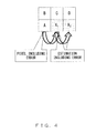
- An example of hierarchical estimation in a prior art is described below with reference to FIG. 6 .
- Patent Document 1 Japanese Laid-open Patent Publication No. 60-127875 Patent.
- Document 2 Japanese Laid-open Patent Publication No. 10-84548
- an image compression apparatus includes a line memory unit, a division unit, a first estimation value calculation unit, a second estimation value calculation unit, and an estimation coding unit.
- the line memory unit holds pixel values for at least one immediately previous line in the lines to be processed of an image to be compressed.
- the division unit divides the pixels of the line to be processed into 2 n -pixel blocks.
- the first estimation value calculation unit extrapolation-estimates the 2 n-1 -th pixel and the 2 n -th pixel in the blocks divided by the division unit using as reference values the values of the pixels immediately above the 2 n-1 -th pixel and the 2 n -th pixel, respectively, and obtains an estimated value in the processing for the first hierarchical level.
- the second estimation value calculation unit interpolation-estimates certain pixels using as reference values the pixel values of the one immediately previous line in the line memory and the estimated, values obtained up to the processing for the immediately previous hierarchical level, and obtains an estimated value in the processing for the second hierarchical level through the processing for the n-th hierarchical level.
- the estimation coding unit obtains an estimation error from the estimated, value obtained in the processes from the processing for the first hierarchical level to the processing for the n-th hierarchical level, converts the estimation error into a quantization number, converts the quantization number into a variable length code, and obtains a compression code.
- the memory only has to include a line memory unit, thereby maintaining a small circuit.
- the compressing process may be performed at a high speed.
- the image decompression apparatus includes a line memory unit, a first estimation value calculation unit, a second estimation value calculation unit, and a decompressed pixel value calculation unit.
- the line memory unit holds, pixel values for at least one immediately previous line in the lines to be processed of an image to be decompressed.
- the division unit divides the pixels of the line to be processed into 2 n -pixel blocks.
- the first estimation value calculation unit extrapolation-estimates the 2 n-1 -th pixel and the 2 n -th pixel in the blocks divided by the division unit using as reference values the values of the pixels immediately above the 2 n-1 -th. pixel and the 2 n -th pixel, respectively, and obtains an estimated value in the processing for the first hierarchical level.
- the second estimation value calculation unit interpolation estimates certain pixels using as reference values the pixel values of the one immediately previous line in the line memory and the estimated values obtained up to the processing for the immediately previous hierarchical level, and obtains an estimated value in the processing for the second hierarchical level through the processing for the n-th hierarchical level.
- the decompressed pixel value calculation unit obtains a quantization number from a compression code, obtains an estimation error quantization value from the quantization number, and obtains a pixel value of a decompressed pixel, using the estimation error quantization value and the estimated value obtained the first estimation value calculation unit or the estimated value obtained by the second estimation value calculation unit.
- the memory only has to include a line memory unit, thereby maintaining a small circuit.
- the decompressing process may be performed at a high speed.
- the image compression apparatus and the image decompression apparatus of the present embodiment include memory for storing about one line of an image and perform MAP (median adaptive predictor) estimation alternately among hierarchical levels in one block, thereby solving the bottleneck in the processing speed in an estimating process for processing with a high image quality and low delay at a high speed as lightweight apparatuses.
- MAP median adaptive predictor
- the MAP estimation is performed by considering the interpolation-estimate on a high resolution component pixel.
- the estimating system may be an extrapolation-estimate for estimating data outside a data sequence, and an interpolation-estimate for estimating in a data sequence.
- the estimation accuracy of the interpolation-estimate is higher because the tendency of the data sequence may be more easily acquired.
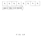
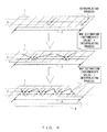
- FIG. 7 illustrates the outline of the estimating method according to an embodiment of the present invention.
- image data is processed in 2 n units (2 n pixels are hereinafter processed as one block).
- the pixels X 1 through X 2 n are pixels to be processed, and X' 1 through X' 2 n form an immediately previous line to the already processed X 1 through X 2 n , that is, the pixels of an immediately previous line.
- the intermediate pixel X 2 n-1 and the last X 2 n in the pixels X 1 through X 2 n are obtained by the extrapolation-estimate using the adjacent pixels X' 2 n-1 and X' 2 n that is, the pixels immediately above.
- the intermediate pixel of the pixels X 2 n is obtained by the MAP estimation in the pixel order of X 2 n-1 and X 2 n-1 + X 2 n-1 using the pixel X 0 to the left of the pixel X 1 (that is, X 2 n in the immediately previous block obtained in the process performed on the immediately previous block), the pixel X 2 n-1 obtained in the processing for the first hierarchical level, and a decompressed pixel value in the immediately previous line.
- the intermediate pixels of the obtained pixels are obtained by the MAP estimation and, in the last processing for the n-th hierarchical level, the intermediate pixel is obtained by the MAP estimation in the pixel order X 1, X 3, ..., and X 2 n-1 .
- the process for the next hierarchical level may be started before completing the current hierarchical process, thereby concurrently performing the processing for two hierarchical levels and performing the entire processing at a high speed.
- the data of the pixels required in the processing is only the data of the pixels in the immediately previous line to the pixel to be processed and the data of the pixels in the block to be processed, it is necessary to provide the memory for about one line of an image for holding the pixel data, thereby maintaining small circuits for the image compression apparatus and the image decompression apparatus.
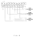
- the pixels X 3 and X 8 are estimated and obtained by the extrapolating process first in the processing for the first hierarchical level on the pixel data of the process line 2 using the pixel data of the immediately previous line 1.
- the pixels X 2 and X 6 are obtained by estimating them in the interpolating process using the pixel data of the immediately previous line 1 and the pixel data obtained in the processing for the first hierarchical level.
- the pixels X1, X3, X5, and X7 are estimated and obtained by the interpolating process using the pixel data of the immediately previous line and the pixel data obtained in the processing for the first and second hierarchical levels.
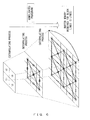
- FIG. 9 practically illustrates the process for each hierarchical level illustrated In FIG. 8 .
- the estimation coding process is practically performed on the basis of the pixel data of the immediately previous line 1 in the lines to be processed and stored in the line memory and the pixel data estimated and obtained for the processed previous hierarchical level.
- the line memory stores the decompressed pixel of each pixel level value for the immediately previous line 1.
- the order of processing the eight pixels In the target pixel block 3 is (1), (2), ..., and (8).
- (1) corresponding to X4 in FIG. 8 is estimated and obtained by the extrapolating process from X' 4 In the Immediately previous line 1 In the line memory.
- (2) corresponding to X8 in FIG. 8 is estimated and obtained by the extrapolating process from X' 8 in the immediately previous line 1 in the line memory.
- (3) corresponding to X 2 in FIG. 8 is obtained by the MAP estimation from the pixels X' 0, X' 2, and X' 4 in the immediately previous line 1 in, the line memory, and the pixels X 0 and X4 obtained in the processes up to the processing for the first hierarchical level of the process line 1.
- (4) corresponding to X 6 in FIG. 8 is 3 obtained the MAP estimation from the pixels X' 4, X' 6, and X' 8 in the immediately previous line 1 in the line memory, and the pixels X 4 and X 8 obtained in the processes up to the processing for the first hierarchical level of the process line 1.
- (5) corresponding to X 1 in FIG. 8 is obtained by the MAP estimation from the pixels X' 0, X' 1, and X' 2 in the immediately previous line 1 in the line memory, and the pixels X 0 and X 2 obtained in the processes up to the processing for the second hierarchical level of the process line 1.
- (6) corresponding to X 3 in FIG. 8 is obtained by the MAP estimation from the pixels X' 2, X' 3, and X' 4 in the immediately previous line 1 in the line memory, and the pixels X 2 and X 4 obtained in the processes up to the processing for the first hierarchical level of the process line 1.
- the above-mentioned processes are performed without waiting for the estimation results by alternately performing the processing on the hierarchical levels in a block in the line direction 4.
- the MAP performs an estimating process of high performance by defining as an estimated value one of the three candidates for and estimated value with the correlations in the vertical and horizontal directions taken into account.
- three candidates for an estimated value may be calculated, with the correlations in the vertical and horizontal directions taken into account by referring to the decompressed pixels of the previous hierarchical level in and after the processing for the second hierarchical level. Therefore, the estimation accuracy may be furthermore improved, and the compression may be realized with high image quality.
- n the number of pixels in the previous block.
- FIG. 10 when the pixels up to the pixel X 6 of the previous block are decompressed, the estimating process of the pixel X 4 of the next block is started.
- the process may be performed with delay. Therefore, the MAP performed with the interpolating process capable of realizing high performance estimation may take sufficient processing time.
- one circuit each is necessary for the estimation, the quantization, and the calculation of a decompressed pixel level value by performing each process with a different timing in the same clock.
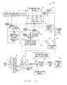
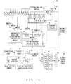
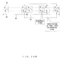
- FIG. 11 is an example of a configuration of an image data compression apparatus 100 according to an embodiment of the present invention.
- the image data 11 input to the image data compression apparatus 100 is a group of pixels to be compressed, and the pixel data is input in the line direction.
- a sequence control circuit 12a controls the order of the processes on the eight pixels of a block to be compressed, and controls the pixel data output from the multiplexer in the image data compression apparatus 100 using a control signal.
- the pixel processing timing of the image data compression apparatus 100 and an image data decompression apparatus 200 described later according to the present embodiment is described below with reference to FIG. 10 .
- the order of the processes on the pixels in one block is illustrated in FIG. 10 . That is, the pixel X 4 is completely processed at the third cloock, the pixel X 8 is completely processed at the fourth clock, the pixel X 5 is completely processed at the fifth clock, the pixel X 2 is completely processed at the sixth clock, the pixel X 6 is completely processed as the seventh clock, the pixel X 7 is completely a processed at the eighth clock, the pixel X 1 is completely processed at the ninth clock, and the pixel X 3 is completely processes at the tenth clock.
- the processes on the pixel X 5 X 7 are those performed on the pixels of the previous block.
- a multiplexer (MUX 1) 13 sequentially allocates the pixels of the image data 11 Input pixel by pixel to the image data compression apparatus 100 for processing in blocks.
- a pixel block 14 to be compressed holds pixel data (level value) of the pixel to be compressed in the current step.
- the pixel data of one immediately previous block is help from the viewpoint of delay process
- a demultiplexer (DMUX 1) 15 passes the pixel level value in the pixel block 14 to be compressed to the processing in the subsequent stages in the order of hierarchical levels.
- An estimating line buffer 16 holds the decompressed pixel level value for at least one immediately previous line of the block to be processed, and passes the value to an immediately above block line memory 17 immediately above the pixel block 14 to be compressed.
- the immediately above block line memory 17 stores a pixel level value of the line immediately above the pixel in the pixel block 14 to be compressed.
- the pixels X' -4, X' -3, X' -2, X' -1, and X' 0 in the immediately above block line memory 17 indicate the pixels of the pixels X' 4, X' 5, X' 6, X' 7, and X' 8 of the previous block.
- a pixel block 18 to be compressed holds a decompressed pixel level value already processed in the pixel of a pixel block 004 to be compressed.
- the pixel level value in the pixel block 18 to be compressed is used in calculating an estimated, value.
- the pixels X-4, X-2, and X 0 in the pixel block 1 to be compressed indicate the previous block pixels X 4, X 6, and X 8 for use in processing the previous block pixels X 5 and X 7.
- demultiplexer (DMUX 2) 19 outputs the level value of the pixel immediately above the pixel to be compressed to an estimated value calculation and selection module 26.
- the pixel immediately above corresponding to the pixel to be estimated output by the demultiplexer 19 is illustrated in C of FIG. 12 .
- a demultiplexer 20 outputs the pixel level value for use in calculating the two immediately above values' average of the pixel to be compressed to a two immediately above values' average calculation module 24.
- the two immediately above values' average corresponding to the pixel two be estimated is indicated by B in FIG. 12 , and the demultiplexer 20 outputs a larger pixel level value between two pixels used in calculating the average value.
- the demultiplexer 20 does not operate.
- a demultiplexer (DMUX 4) 21 outputs a pixel level value used in calculating a two immediately above values' average of a pixel to be compressed to the two immediately above values' average calculation module 24.
- the two immediately above values' average corresponding to the pixel to be estimated is illustrated by B in FIG. 2 , and the demultiplexer 21 outputs a pixel level value having a larger value in the two pixels used in calculating an average value.
- the demultiplexer (DMUX 4) 21 does not operate when the pixel to be estimated is the pixel X 4 or X 8 processed, in the processing for the first hierarchical level.
- the demultiplexer (DMUX 5) 22 outputs the pixel level value of the pixel for use in calculating the current line two-value average of the pixel to be compressed to a current line two-value average calculation module 25.
- the current line two-value average corresponding to the pixel to be estimated is indicated by A in FIG. 12 , and the demultiplexer 22 outputs a pixel having a smaller value between the two pixels used in calculating the average value.
- the demultiplexer 22 does not operate.
- a demultiplexer (DMUX 6) 23 outputs the pixel level value of the pixel for use in calculating the current line two-value average of the pixel to be compressed to the current line two-value average calculation module 25.
- the current line two-value average corresponding to the pixel to be estimated is indicated by A in FIG. 12 , and the demultiplexer 23 outputs a pixel having a larger value between the two pixels used in calculating the average value.
- the demultiplexer 23 does not operate.
- the two immediately above values average calculation module 24 calculates an average value between two-value in the vicinity immediately above the pixel to be compressed.
- the current line two-value average corresponding to the pixel to be estimated is indicated by A in FIG. 12 .
- the two immediately above values average calculation module 24 does not operate when the pixels to be estimated are the pixels X 4 and X 8 processed in the processing for the first hierarchical level.
- the estimating system is higher in estimation accuracy by the interpolation, estimate for estimation by already decompressed pixels enclosing the pixel to be estimated than by the extrapolating estimate for estimation of a pixel level value outside the pixel to be compressed and the already decompressed pixel level value. Therefore, if the interpolating process is performed on the reference value A in the previous line, the estimation accuracy may be furthermore improved.
- the current line two-value average calculation module 25 calculates a pixel to be compressed and an average value between two values of two adjacent pixels.
- the current line two-value average calculation module 25 does not operate when the pixels to be estimated, are the pixels X 4 and X 8 processed in the processing for the first hierarchical level.
- the estimating system has a higher estimation accuracy for the interpolation estimate when estimating using already decompressed pixels enclosing the pixel to be estimated than using the extrapolating estimate for estimation of a pixel level value outside the pixel to be compressed and the already decompressed pixel level value. Tnerefore, if the interpolating process is performed on the reference value A in the same line, the estimation accuracy may be further improved.
- the estimated value calculation and selection module 26 calculates and selects an estimated value according to a control signal from the sequence control circuit 12a on the basis of the pixel immediately above the pixel to be compressed, the two immediately above values' average, and a current line two-value average.
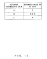
- FIG. 13 illustrates a reference intermediate value and a corresponding estimated value. Only the pixel immediately above the pixel to be compressed is used in the processing for the first hierarchical level in calculating an estimated value by the estimated value calculation and selection module 26. However, in the processing in and after the processing for the second hierarchical level, the estimated value calculation and selection module 26 calculates the intermediate values with the current line two-value average set as A, the two immediately above values' average set as B, and the pixel immediately above set as C, and determines an estimated value to be used from among A, C, and A + C - B to satisfy the relationships illustrated in FIG. 13 .
- An estimated value 27 is an estimated value calculated by the estimated value calculation and selection module 26.
- a subtracter 28 subtracts the estimated value 27 from the pixel to be compressed output from the demultiplexer 15, and calculates an estimation error.
- a quantizer 29 quantizes the estimation error as a difference value between the pixel to be compressed and the estimated value.
- the quantizer 29 receives the estimation error and outputs a quantization value and a quantization number.
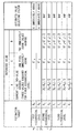
- the estimation error, the estimation error quantization value, and the quantization number are associated with one another as illustrated in FIG. 14 . According to the table in FIG. 14 , the quantizer 29 outputs a corresponding estimation error quantization value and quantization number from the input estimation error.
- An adder 30 adds the estimated value 27 to the estimation error quantization value output from the quantizer 29, calculates a decompressed pixel level value, and outputs it to a multiplexer (MUX 2) 31 and a multiplexer (MUX 3) 32.
- MUX 2 multiplexer
- MUX 3 multiplexer
- the multiplexer (MUX 2) 31 outputs the decompressed pixel level values X 2, X 4, X 6, and X 8 to the pixel block 18 to be compressed.
- the multiplexer (MUX 3) 32 sequentially outputs the decompressed pixel level values to the estimating line buffer 16.
- a variable length coder 33 receives the quantization number output from the quantizer 29, converts it into a variable length code such as a Huffman code, etc., and outputs the code.
- a compression code buffer 34 accumulates the variable length codes output from the variable length coder 33.
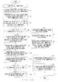
- FIG. 15 is a flowchart of the operating process of the image data compression apparatus 100 according to an embodiment of the present invention when image data is compressed.
- the image data compression apparatus 100 when the process is started and the image data 11 is input to the image data compression apparatus 100, the image data compression apparatus 100 first stores eight pixels of the image data 11 in the pixel block 14 to be compressed in step S1.
- step S2 the image data compression apparatus 100 stores the pixel level values corresponding to the pixels X' -4, X' -3, X' -2, X' -1, X' 0, X' 1, X' 2, X' 3, X' 4, X' 5, X' 6, X' 7, and X' 8 in the immediately above block line memory.
- step S3 the pixel block 14 to be compressed overwrites the pixel level values of the pixels X 4, X 6, and X 8 of a previous block according to the control signal from the sequence control circuit on the pixels X -4, X -2, and X 0
- step S4 if the pixel to be compressed is the pixel X 4 orX 8 to be processed in the processing for the first hierarchical level (YES in step S4), then the processing for the first hierarchical level is performed in step S5, that is, the estimated, value calculation and selection module 26 outputs as the estimated values 27 the pixel level values of the pixel immediately above X' 4 and X' 8 of the pixels to be processed X 4 and X 8 output from the demultiplexer (DMUX 2) 19.
- DMUX 2 demultiplexer
- step S4 if the pixels to be compressed are not the pixels X 4 and X 8 to be processed in the processing for the first hierarchical level (NO in step S4), then the pixels are to be processed in and after the processing for the second hierarchical level. Therefore, to perform the MAP estimation, the two immediately above values' average calculation module 24 calculates the two immediately above values' average on the basis of the values selected and output by the demultiplexer (DMUX 3) 20 and the demultiplexer (DMUX 4) 21 in step S6, and the current line two-value average calculation module 25 calculates the current line two-value average on the basis of the values selected and output by the demultiplexer (DMUX 5) 22 and the demultiplexer (DMUX 6) 23 in step S7. Then, in step S8, the estimated value calculation and selection module 26 calculates an estimated value 26 using the pixel immediately above and the two immediately above values' average and the current line two-value average obtained in steps S6 and S7.
- the subtracter 28 subtracts the estimated value 27 from the pixel level value of the pixel to be compressed, selected, and output by the demultiplexer (DMUX 1) from the pixel block 14 to be compressed in step S9, and calculates an estimation error.
- the quantizer 29 quantizes the estimation error calculated in step S9, and outputs an estimation error quantization value and a quantization number.
- the adder 30 adds the estimation error quantization value to the estimated value 27 in step S11, obtains a decompressed pixel, and outputs it to the multiplexer (MUX 2) 31 and the multiplexer (MUX 3) 32.
- the multiplexer (MUX 2) 31 holds the decompressed pixels of the pixels X 2, X 4, X 6, and X 8 in the pixel block 18 to be compressed in step S13. If the pixels to be compressed are other than X 2, X 4, X 6, and X 8 in step S12 (NO In step S12), then the processes in step S13 are omitted. Then, in the image data compression apparatus 100, the multiplexer (MUX 3) 32 passes the decompressed pixels to the estimating line buffer 16 in step S14.
- variable length coder 33 generates a code on the basis of the quantization number.
- the type of the code used in this process may be a Golomb code or an arithmetic code.
- high precision estimation- may be realized because of the execution of the calculation of an intermediate value by reference to and interpolation of a decompressed value of the previous line and the previous hierarchical level
- FIG. 16 is an example of a configuration of the image data decompression apparatus 200 according to the present embodiment.
- the components of the portion for obtaining the estimated value 27 have basically the some operation as the components of the image data compression apparatus 100, and are assigned the same reference numerals. Detailed descriptions of these components are omitted here.
- the compression code 41 is obtained by coding image data, and is to be decompressed by the image data decompression apparatus 200 according to the present embodiment.
- An inverse coder 42 receives the compression code 41, and outputs a quantization number corresponding to the compression code 41.
- An inverse quantizer 43 receives the quantization number output from the inverse coder 42, and outputs an estimation error quantization value 44.
- the quantization number and the estimation error quantization value have the relationship illustrated in FIG. 17 , and it is obviously the same as the relationship between the estimation error quantization value and the quantization number illustrated in FIG. 14 .
- the inverse quantizer 43 outputs the estimation error quantization value 44 corresponding to the input quantization number.
- the estimation error quantization value 44 is a quantization value of the estimation error output from the inverse quantizer 43.
- a sequence control circuit 12b controls the order of processing of eight pixels of a block to be decompressed by outputting a control signal to control the output of each multiplexer (MuX) and demultiplexer (DMUX).
- the order of processing pixels is pixels X 4, X 8, X 5, X 2, X 6, X 7, X 1, ard X 3, which is similar to the order illustrated in FIG. 10 .
- the pixels X 5 and X 7 are processed using the pixels in the immediately previous block.
- An adder 45 adds the estimated value 27 to the decompressed pixel level value.
- a multiplexer (MUX 1) 46 allocates the pixel decompressed pixel by pixel sequentially to a decompression completion pixel block 47.
- the decompression completion pixel block 47 holds a pixel level value for which the decompression is completed in the current decompressing process.
- a demultiplexer (DMUX1) 48 rearranges the pixel data in the decompression completion pixel block 47 in the order of the data before the compression (X 1, X 2, X 3, X 4, X 5, X 6, X 7, and X 8) and outputs the data.
- Decompressed image data 49 is a result of the decompression by the image data decompression apparatus 200.
- FIG. 16 Described next is the operation of the image data decompression apparatus 200 illustrated in FIG. 16 when the compressed data is decompressed.
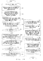
- FIG. 18 is a flowchart of the operating process of the image data decompression apparatus 200 according to the present embodiment when compressed data is decompressed.
- the inverse coder 42 obtains a quantization number on the basis of the input compression code 41 first in step S21.
- step S22 in the image data decompression apparatus 200 the inverse quantizer 43 obtains the estimation error quantization value 44 on the basis of the quantization number obtained in step S21. Then, in step 323, the immediately above block line memory 17 holds the pixel level values corresponding to the pixels X' -4, X' -3, X' -2, X' -1, X' 0, X' 1, X' 2, X' 3, X' 4, X' 5, X' 6, X' 7, and X' 3 output from the estimating line buffer 16.
- step S24 in the pixel block 18 to be compressed, the values of the pixels X 4, X 6, and X 8 of the previous block are overwritten on the X -4, X -2, and X 0 on the basis of the control signal from the sequence control circuit 12b.
- step S25 the image data decompression apparatus 200 determines whether or not the pixel to be decompressed is X 4 or X 8 If the pixel is X 4 or X 8 (YES in step S25), the estimated value calculation and selection module 26 outputs the pixel level value of the pixel immediately above the pixel to be compressed and output from the demultiplexer (DMUX 2) 19 as the estimated value 27.
- DMUX 2 demultiplexer
- step S25 If the pixel to be decompressed is not X 4 or X 8 in step S25 (NO in step S25), then the two immediately above values' average calculation module 24 calculates the selected two immediately above values' average from the values selected and output by the demultiplexer (DMUX 3) 20 and the demultiplexer (DMUX 4) 21, and outputs the result of the calculation to the estimated value calculation and selection module 26 in step S27.
- step S28 the current line two-value average calculation module 25 calculates a reference value from the value selected and output by the demultiplexer (DMUX 5) 22 and the demultiplexer (DMUX 6) 23, and outputs the value to the estimated value calculation and selection module 26.
- step S29 the estimated value calculation and selection module 26 obtains the estimated value 27 with reference to FIGS. 12 and 13 on the basis of the two immediately above values' average obtained in step S27 and the current line two-value average obtained in step S28.
- the adder 45 adds in step S30 the estimation error quantization value 44 to the estimated value 27 obtained in step S22 in the image data decompression apparatus 200, and calculates a decompressed pixel.
- step S30 When the decompressed pixels calculated in step S30 are pixels X 2, X 4, X 6, and X 8 (YES in step S31), the multiplexer (MUX 2) 31 Inputs the pixels to the pixel block 18 to be Compressed. If they are decompressed pixels of other pixels (NO in step S31), then step S31 is omitted.
- the multiplexer (MUX 3) 32 inputs the decompressed pixels to the estimating line butter 16.
- the image data decompression apparatus 200 inputs all decompressed pixels to the decompression completion, pixel block 47 in step S34.
- the demultiplexer (DMUX 1) 48 outputs the decompressed pixels in the decompression completion pixel block 47 in the order before the compression (X 1, X 2, X 3, X 4, X 5, X 6, X 7, and X 8).
- the processing in steps S21 through S35 is repeated on all image data, and when the decompressing process is completed on all image data, the present processing is terminated.
- the pixels in a line are divided into blocks, and the processing timing is shifted for each hierarchical level in the block, thereby solving the bottleneck in processing speed of an estimating process.
- high precision estimation may be realized because of the execution of the calculation of an intermediate value by reference to and interpolation of a decompressed value of the previous line and the previous hierarchical level.
- FIG. 19 illustrates the position of the image data in one frame when exception handling is performed in the image data compressing process and decompressing process in the present embodiment.
- 0 ⁇ 80 refers to 80 in hexadecimal notation, and corresponds to 128 in decimal notation.
- 128 is half the value of 256 gradations of gray scale for the pixels.
- the extrapolating process is performed by assuming that the value 128 (0 ⁇ 80) exists so as to obtain an estimated value.
- the value of the corresponding pixel of the previous block is used as an estimated value.
- the interpolating process is performed to obtain an estimated value by assuming that there are 0 ⁇ 80 gray-scale gradations (128 in decimal notation, which is half the value of 256 gray-scale gradations) in the position of a non-existent pixel.
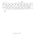
- FIG. 21 is an example of a substitute pixel when an estimated value of the pixel in the leftmost position of (3) illustrated in FIG. 19 is obtained.
- the value of the pixel X' 1 is used as a substitute pixel in the position of the pixel X' 0 of a pixel immediately above 52 and the position of the pixel X 0 process line 53.
- a reference value is configured by using substitute pixels in the positions of X' 9 and X9.
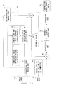
- FIG. 22 is an example of a program configuration of a date compression program 300 in the present embodiment.
- the configuration unit of the data compressing program 300 in FIG. 22 is realized by the CPU executing the data compressing program 300 in the memory.
- the data compressing program 300 may be configured as one program or as a program group formed by a plurality of programs.
- image data 61 is the data of pixels (gray scale values) to be compressed by the data compressing program 300 according to the present embodiment.
- the image data 61 is input to the data compressing program 300 in the line direction.
- An image format 62 is the information about the horizontal image size of the image data 61, and is input into the data compressing program 300 when the data compressing process is performed.
- a hierarchical level access unit 63 is a program unit for classifying each pixel into a hierarchical level on the basis of the horizontal image size of the frame of an image, and accessing each piece of pixel data to perform a coding process for each hierarchical level.
- the hierarchical level is N
- the processes are not to be concurrently performed, unlike the case in which the compressing process is performed by hardware as described above. Therefore, the blocks are divided and a pixel is selected in each hierarchical level as follows, unlike in the conventional methods.
- a memory area 64 for the line to be compressed holds a level value of the pixel of the line to be compressed in the current step, and is provided in the memory area of the information processing device by the data compressing program 300.
- An estimating line memory area 66 holds the decompressed pixel level value of the immediately previous line to the process line, and is provided in the memory area of the information processing device by the data compressing program 300.
- a current line two-value average calculation, unit 67 is a program unit for calculating the pixel to be compressed and an average value of the two adjacent values.
- the calculating process is performed in and after the second hierarchical level, and the calculating method is expressed as follows.
- a two immediately above values average calculation unit 68 is a program unit for calculating an average value of two values in the vicinity immediately above the pixel to be compressed. The calculation is also performed in and after the second hierarchical level, and the calculating method is described as follows.
- An estimated value calculation, and selection unit 69 is a program unit for calculating and selecting an estimated value on the basis of the pixel immediately above, the two immediately above values average, and the current line two-value average.
- a quantization unit 71 is a program unit for quantizing an "estimation error" as a difference between the pixel to be compressed, and the estimated value.
- the quantization unit 71 receives the estimation error and outputs an estimation error quantization value and a quantization number.
- the relationship among the estimation error, the estimation error quantization value, and the quantization number are illustrated in Fig. 14 .
- a variable length coding unit 72 is a program unit for receiving a quantization number, and outputting a variable length code.
- a compression code memory area 73 is a buffer for accumulating a variable length code output from the variable length coding unit 72 as a compression code.
- the compression code memory area 73 is reserved by the data compressing program 300 in the memory of the information processing device for executing the data compressing program 300.
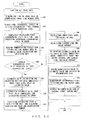
- FIG. 23 is a flowchart of the operating process of the data compression program 300 when image data is compressed. The process illustrated in FIG. 23 is realized by the CPU of the information processing device executing the data compressing program 300 on the memory.
- step S42 When the process in FIG. 23 is started, one line of the image data 61 is stored in the memory area 64 for the line to be compressed first in step S41. Next, in step S42, one block of pixels to be compressed is classified into pixels to be processed in the processing for the N-th hierarchical level.
- step S343 the estimated value calculation and selection unit 69 reads data from the estimating line memory area 66. If the current process is the processing for the first hierarchical level (YES in step S44), the estimated value calculation and selection unit 69 defines the pixel level value of the pixel immediately above the pixel to be compressed as an estimated value as the processing for the first hierarchical level in step S45.
- step S44 if the current process is the processing for the second or subsequent hrerarchical level (NO in step S44), the two immediately above values average calculation unit 68 calculates a two immediately aboves values average in step S46, the current line two-value average calculation unit 67 calculates a current line two-value average in step S47, and an estimated value of the pixel to be compressed is obtained in step S49 using the two immediately above values average calculated in step S46 and the current line two-value average calculated in step S47.
- the subtraction unit 65 subtracts the estimated value from the pixel level value of the pixel to be compressed and calculates an estimation error in step S49. Then, in step S50, the quantization unit p71 quantizes the estimation error obtained in step S49, and obtains a quantization value and a quantization number.
- step S51 an addition unit 70 adds the quantization value obtained in step S50 to the estimated value obtained in step 345 of S48, and calculates a decompressed pixel.
- step S52 the decompressed pixel is stored in the estimating line memory area 66.
- variable length coding unit 72 converts data into a variable length code, generates a compression code, and stores it in the compression code memory. area 73.
- the compression code may be a Golomb code or an arithmetic code.
- steps S43 through S53 are performed in the processing for the first hierarchical level on all blocks in one line, and the processing is performed on each hierarchical level.
- the processes in S41 through S53 are performed on all image data, and a compression code is generated, the current processing is terminated.
- the image data compression according to the present embodiment may be performed by software rather than hardware.
- exception handling is performed in the orocessing in FIG. 23 .
- the pixels correspond to the portions (1) and (2) in the first line, there is no local decode value immediately above. Therefore, the following value is defined as an estimated value without using the central value among the reference values A through C in FIG. 12 .
- the portions (3) and (4) corresponding to the leading and trailing blocks in the second and subsequent lines configure a reference value by using the following substitute pixels.
- the portions (1) and (2) are described above with reference to FIG. 21 .
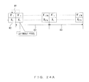
- FIG. 24A illustrates an estimated value calculated in the position of (3) illustrated in FIG. 19 .
- an estimated value of each block 33 is obtained by assuming that there is a pixel having a pixel level value of the leftmost pixel of the previous line 81 to the left end of the previous line 81 and the current line 82.
- FIG. 24B illustrates an estimated value calculated in the position of (4) illustrated in FIG. 19 .
- the number of pixels short in one block at the right end of the previous line 81 and the current line 82 it is assumed, that there is a pixel of the pixel level value at the right end of the immediately previous block, and an estimated value of each block 83 is obtained.
- FIG. 25 is an example of a program configuration of the data decompression program 400 according to the present embodiment.
- the configuration unit of the data decompressing program 400 in FIG. 25 is realized by the CPU executing the data compressing program 300 in the memory.
- the data decompressing program 400 may be configured as one program or as a program group formed by a plurality of programs.
- the components for obtaining an estimated value perform basically the same operations as the components or the data compressing program 300 in FIG. 22 , and are assigned the same reference numerals. Therefore, detailed descriptions are omitted for these components.
- a compression code 91 is coded image data, and is to be decompressed by the data decompressing program 400.
- An inverse coding unit 92 is a program unit for converting the compression code 91 into a corresponding quantization number.
- An inverse quantization unit 93 converts the quantization, number converted by the inverse quantization unit 93 into an estimation error quantization value.
- the quantization number and the estimation error quantization value have the relationship illustrated In FIG. 17 at described above, and the inverse quantization unit 93 converts the quantization number into the estimation error quantization value.
- An addition unit 94 is a program unit for adding the estimation error quantization value to the estimated value and obtaining a decompressed pixel.
- a completely decompressed pixel block area 95 is a memory area for storing pixel level values of decompressed pixels in one block, and is reserved by the data decompressing program 400 in the memory of the information processing device for executing the data decompressing program 400.
- a sequence conversion unit 96 is a program unit for reading a pixel level value from the completely decompressed pixel block area 95 in the order before the compression.
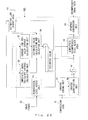
- FIG. 26 is a flowchart of the operating process of a data decompressing program 400 when image data is decompressed.
- the process in FIG. 26 is realized by the CPU of the information processing device executing the data decompressing program 400 in the memory.
- the inverse coding unit 92 first converts the compression code 91 into a quantization number in step S61.
- the inverse quantization unit 93 acquires an estimation error quantization value based, on the quantization number obtained in step S61.
- step S63 the estimated value calculation and selection unit 69 reads the pixel level value of the block immediately above the block to be decompressed from the estimated value line memory area. It the current pixel to be processed is processed in the processing for the first hierarchical level (YES in step S64), then the estimated value calculation and selection unit 69 outputs the pixel level value of the pixel immediately above the pixel to be processed, as an estimated value in step S65.
- the two immediately above values average calculation unit 68 calculates a two immediately above values average in step S65
- the current line two-value average calculation unit 67 calculates a current line two-value average in step S66 and obtains an estimated value of the pixel to be compressed using the two immediately above values average calculated in step S66 and the current line two-value average calculated in step S67 in step S68.
- the audition unit 94 adds the pixel level value of the pixel to be compressed to the estimated value, and calculates a decompressed pixel in step S69.
- step S70 the decompressed pixel calculated in seep S69 is stored in the estimating line buffer memory area 65, and stores the decompressed pixel in the completely or decompressed pixel block area 95 step S71.
- sequence conversion unit 96 reads the pixel level value of the decompressed pixel from the completely decompressed pixel block area 95 in the order of the image data before the compression, and outputs the value.
- the output value is decompressed image data.
- the decompressing process by the data 7 decompressing program 400 is completed by repeating the processes in steps S61 through S72 for each piece of all-compressed image data.
- the image data decompressing process according to the present embodiment may also be realized using software by executing the data decompressing program 400.
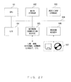
- FIG. 27 illustrates a system environment of the information processing device for executing the data compressing program 300 and the data decompressing program 400.
- the information processing device includes a CPU 101, main storage 102 such as RAM etc., auxiliary-storage 103 such as a hard disk etc., an input/output device (I/O) 104 such as a display,a keyboard, a pointing device, etc., a network connection device 105 such as a communication interface, a modem, etc., and a medium reader 106 for reading stored content from a portable storage medium such as a disk, a magnetic tape, etc.
- I/O input/output device
- a network connection device 105 such as a communication interface, a modem, etc.
- a medium reader 106 for reading stored content from a portable storage medium such as a disk, a magnetic tape, etc.
- the CPU 101 executes a program on the auxiliary storage 103 and a program installed through the network connection device 105 by using the main storage 102 as work memory, thereby realizing the function of each component of the data compressing program 300 and the data decompressing program 400 illustrated in FIGS. 22 and 25 , and realizing the processes according to the flowcharts illustrated in FIGS. 23 and 26 .
- a medium reader 107 reads a program and data stored in the storage medium 108 such as a magnetic tape, a flexible disk, CD-ROM, an MO, a DVD, etc., and loads them into a connection management server 10 in the present embodiment through the medium reader 106.
- the program, and data is stored in the main storage 102 and the auxiliary storage 103, and executed and used by the CPU 101, hereby realizing the processes according to the flowcharts as if the operation were performed by software
- the present invention is not limited to the image data compression apparatus, decompression, apparatus, compressing process, decompressing process, or program, but may be configured as a computer-readable storage medium 107 and program used to direct a computer to perform the function according to the above-mentioned embodiments of the present invention when it is used by the computer.
- the "storage medium” may be a portable storage medium 116 that may be attached to and detached from a medium drive device 117 such as a CD-ROM, a flexible disk (or an MO, DVD, a memory card, a removable hard disk, etc.), a storage unit (database etc.) 112 in an external device (a server etc.) transmitted through a network circuit 113, or memory (RAM or hard disk etc.) 115 in a body 114 of an information processing device 111, etc.
- a program stored in the portable storage medium 116 and the storage unit (database etc.) 112 is loaded into the memory (RAM or hard disk etc.) 115 in the body 114 and executed.
- the storage medium such as the above-mentioned CD-ROM, DVD-ROM may be, in addition to the above-mentioned examples, a next generation optical disk storage media using blue lasers such as Blue-ray Disc (registered trademark), AOD (advanced optical disc), etc., a next generation optical disk storage media using red lasers such as HD-DVD9, Blue Laser DVD and hologram using blue-violet lasers, etc., to embody the present invention using various types of large capacity storage mediums to be developed hereafter,
- blue lasers such as Blue-ray Disc (registered trademark), AOD (advanced optical disc), etc.
- red lasers such as HD-DVD9, Blue Laser DVD and hologram using blue-violet lasers, etc.
- the pixels in a line are divided into blocks, and the processing timing is shifted in every hierarchical level in a block, thereby solving the bott leneck problem in processing speed in the estimating process.
- high precision estimation may be realized because of the execution of the calculation of an intermediate value by reference to and interpolation of a decompressed value of the previous line and the previous hierarchical level.
Landscapes
- Engineering & Computer Science (AREA)
- Multimedia (AREA)
- Signal Processing (AREA)
- Compression Or Coding Systems Of Tv Signals (AREA)
- Compression Of Band Width Or Redundancy In Fax (AREA)
Applications Claiming Priority (1)
| Application Number | Priority Date | Filing Date | Title |
|---|---|---|---|
| PCT/JP2008/000836 WO2009122463A1 (fr) | 2008-03-31 | 2008-03-31 | Appareil de compression de données d'image, appareil de décompression, procédé de compression, procédé de décompression et programme |
Publications (2)
| Publication Number | Publication Date |
|---|---|
| EP2273776A1 true EP2273776A1 (fr) | 2011-01-12 |
| EP2273776A4 EP2273776A4 (fr) | 2014-07-16 |
Family
ID=41134885
Family Applications (1)
| Application Number | Title | Priority Date | Filing Date |
|---|---|---|---|
| EP08720702.3A Withdrawn EP2273776A4 (fr) | 2008-03-31 | 2008-03-31 | Appareil de compression de données d'image, appareil de décompression, procédé de compression, procédé de décompression et programme |
Country Status (5)
| Country | Link |
|---|---|
| US (1) | US8411976B2 (fr) |
| EP (1) | EP2273776A4 (fr) |
| JP (1) | JP4756665B2 (fr) |
| KR (1) | KR101172983B1 (fr) |
| WO (1) | WO2009122463A1 (fr) |
Families Citing this family (5)
| Publication number | Priority date | Publication date | Assignee | Title |
|---|---|---|---|---|
| TW201016017A (en) * | 2008-10-08 | 2010-04-16 | Univ Nat Taiwan | Memory management method and system of video encoder |
| US8934028B2 (en) * | 2011-12-15 | 2015-01-13 | Samsung Electronics Co., Ltd. | Imaging apparatus and image processing method |
| GB2578769B (en) | 2018-11-07 | 2022-07-20 | Advanced Risc Mach Ltd | Data processing systems |
| GB2583061B (en) * | 2019-02-12 | 2023-03-15 | Advanced Risc Mach Ltd | Data processing systems |
| US10971079B2 (en) * | 2019-08-20 | 2021-04-06 | Apple Inc. | Multi-frame-history pixel drive compensation |
Citations (6)
| Publication number | Priority date | Publication date | Assignee | Title |
|---|---|---|---|---|
| US20060050972A1 (en) * | 2004-07-21 | 2006-03-09 | Amimon Ltd. | Interpolation image compression |
| EP1761064A2 (fr) * | 2005-09-06 | 2007-03-07 | Samsung Electronics Co., Ltd. | Appareil et procèdè de prédiction de codage et dècodage vidéo pour trames intra-predictives |
| US20070121731A1 (en) * | 2005-11-30 | 2007-05-31 | Akiyuki Tanizawa | Image encoding/image decoding method and image encoding/image decoding apparatus |
| US20070206872A1 (en) * | 2006-03-03 | 2007-09-06 | Samsung Electronics Co., Ltd. | Method of and apparatus for video intraprediction encoding/decoding |
| WO2007132539A1 (fr) * | 2006-05-17 | 2007-11-22 | Fujitsu Limited | Dispositif, procédé et programme de compression de données d'image, et dispositif, procédé et programme de décompression de données d'image |
| CA2659351A1 (fr) * | 2006-07-28 | 2008-01-31 | Kabushiki Kaisha Toshiba | Procede et appareil de codage et de decodage d'image |
Family Cites Families (14)
| Publication number | Priority date | Publication date | Assignee | Title |
|---|---|---|---|---|
| JPS6087570A (ja) * | 1983-10-20 | 1985-05-17 | Matsushita Graphic Commun Syst Inc | 画信号内插方式 |
| JPS60127875A (ja) * | 1983-12-15 | 1985-07-08 | Kokusai Denshin Denwa Co Ltd <Kdd> | 2値画像の符号化方式 |
| JPS62264785A (ja) * | 1986-05-13 | 1987-11-17 | Fujitsu Ltd | 並列処理回路 |
| US5475501A (en) * | 1991-09-30 | 1995-12-12 | Sony Corporation | Picture encoding and/or decoding method and apparatus |
| US6965644B2 (en) * | 1992-02-19 | 2005-11-15 | 8×8, Inc. | Programmable architecture and methods for motion estimation |
| US5960116A (en) * | 1995-11-02 | 1999-09-28 | Canon Kabushiki Kaisha | Image processing apparatus and method for performing prediction data encoding |
| US6292591B1 (en) * | 1996-07-17 | 2001-09-18 | Sony Coporation | Image coding and decoding using mapping coefficients corresponding to class information of pixel blocks |
| US6072830A (en) * | 1996-08-09 | 2000-06-06 | U.S. Robotics Access Corp. | Method for generating a compressed video signal |
| JP3348612B2 (ja) * | 1996-10-31 | 2002-11-20 | 日本ビクター株式会社 | ブロック間予測符号化装置、ブロック間予測復号化装置、ブロック間予測符号化方法、ブロック間予測復号化方法、及びブロック間予測符号化復号化装置 |
| JP3861957B2 (ja) * | 1998-02-03 | 2006-12-27 | ソニー株式会社 | 記憶装置、並びに書き込み方法および読み出し方法 |
| US6633677B1 (en) * | 1999-12-30 | 2003-10-14 | Stmicroelectronics, Inc. | Method and apparatus for processing an image in an image compression/decompression system that uses hierachical coding |
| US6907075B2 (en) * | 2000-06-30 | 2005-06-14 | Koninklijke Philips Electronics N.V. | Encoding method for the compression of a video sequence |
| US6853755B2 (en) * | 2001-03-28 | 2005-02-08 | Sharp Laboratories Of America, Inc. | Method and apparatus for adaptive compression of scanned documents |
| FR2852773A1 (fr) * | 2003-03-20 | 2004-09-24 | France Telecom | Procedes et dispositifs de codage et de decodage d'une sequence d'images par decomposition mouvement/texture et codage par ondelettes |
-
2008
- 2008-03-31 EP EP08720702.3A patent/EP2273776A4/fr not_active Withdrawn
- 2008-03-31 JP JP2010505043A patent/JP4756665B2/ja not_active Expired - Fee Related
- 2008-03-31 WO PCT/JP2008/000836 patent/WO2009122463A1/fr active Application Filing
- 2008-03-31 KR KR20107022260A patent/KR101172983B1/ko not_active IP Right Cessation
-
2010
- 2010-09-21 US US12/887,014 patent/US8411976B2/en not_active Expired - Fee Related
Patent Citations (6)
| Publication number | Priority date | Publication date | Assignee | Title |
|---|---|---|---|---|
| US20060050972A1 (en) * | 2004-07-21 | 2006-03-09 | Amimon Ltd. | Interpolation image compression |
| EP1761064A2 (fr) * | 2005-09-06 | 2007-03-07 | Samsung Electronics Co., Ltd. | Appareil et procèdè de prédiction de codage et dècodage vidéo pour trames intra-predictives |
| US20070121731A1 (en) * | 2005-11-30 | 2007-05-31 | Akiyuki Tanizawa | Image encoding/image decoding method and image encoding/image decoding apparatus |
| US20070206872A1 (en) * | 2006-03-03 | 2007-09-06 | Samsung Electronics Co., Ltd. | Method of and apparatus for video intraprediction encoding/decoding |
| WO2007132539A1 (fr) * | 2006-05-17 | 2007-11-22 | Fujitsu Limited | Dispositif, procédé et programme de compression de données d'image, et dispositif, procédé et programme de décompression de données d'image |
| CA2659351A1 (fr) * | 2006-07-28 | 2008-01-31 | Kabushiki Kaisha Toshiba | Procede et appareil de codage et de decodage d'image |
Non-Patent Citations (2)
| Title |
|---|
| MARCELO J WEINBERGER ET AL: "The LOCO-I Lossless Image Compression Algorithm: Principles and Standardization into JPEG-LS", IEEE TRANSACTIONS ON IMAGE PROCESSING, IEEE SERVICE CENTER, PISCATAWAY, NJ, US, vol. 9, no. 8, 1 August 2000 (2000-08-01), XP011025643, ISSN: 1057-7149, DOI: 10.1109/83.855427 * |
| See also references of WO2009122463A1 * |
Also Published As
| Publication number | Publication date |
|---|---|
| US20110013854A1 (en) | 2011-01-20 |
| KR101172983B1 (ko) | 2012-08-09 |
| US8411976B2 (en) | 2013-04-02 |
| EP2273776A4 (fr) | 2014-07-16 |
| WO2009122463A1 (fr) | 2009-10-08 |
| JP4756665B2 (ja) | 2011-08-24 |
| KR20100122947A (ko) | 2010-11-23 |
| JPWO2009122463A1 (ja) | 2011-07-28 |
Similar Documents
| Publication | Publication Date | Title |
|---|---|---|
| US8311107B2 (en) | Image data compression device, compressing method, image data decompression device, decompressing method, and recording medium | |
| US8908982B2 (en) | Image encoding device and image encoding method | |
| KR20070046852A (ko) | 혼합된 그래픽 및 비디오 소스의 압축을 위한 시스템 및방법 | |
| US20120308128A1 (en) | Image data coding apparatus, method of controlling operation of same, and program therefor | |
| US8411976B2 (en) | Image data compression apparatus, decompression apparatus, compressing method, decompressing method, and storage medium | |
| US8358861B2 (en) | Image compression device and image decompression device | |
| KR20010043394A (ko) | 정보 스트림 디코더에서 메모리 자원 이용을 증가시키는방법 및 장치 | |
| JP2004356850A (ja) | 圧縮動画像の伸張装置及びそれを用いた画像表示装置 | |
| JP2010098352A (ja) | 画像情報符号化装置 | |
| WO2012160626A1 (fr) | Dispositif de compression d'image, dispositif de restauration d'image et programme | |
| US20110299790A1 (en) | Image compression method with variable quantization parameter | |
| US8306341B2 (en) | Image data compression apparatus and decoding apparatus | |
| US20110110424A1 (en) | Video Encoder and Data Processing Method | |
| WO2007148425A1 (fr) | Dispositif de compression et de rétablissement d'image et programme correspondant | |
| US8467619B2 (en) | Image compressing apparatus, image compressing method, image decompressing apparatus, and storage medium | |
| US20130223516A1 (en) | Block quantizer in h.264 with reduced computational stages | |
| US10284879B2 (en) | Image processing apparatus and method based on integerprecision image data | |
| JP2020092327A (ja) | 画像符号化装置、画像符号化方法、およびプログラム | |
| EP2315445A1 (fr) | Compression vidéo | |
| CN110300303B (zh) | 编码装置、显示装置、编码装置的控制方法、及计算机能够读取的记录介质 | |
| JP2009038740A (ja) | 画像符号化装置 | |
| JP2001128182A (ja) | 画像符号化方法および画像符号化プログラムを格納したコンピュータで読取可能な記録媒体 | |
| JP3227170B2 (ja) | 画像符号化装置 | |
| JP3397682B2 (ja) | 画像符号化装置 | |
| JPH10313403A (ja) | 静止画撮像装置、カラー複写装置及び表示装置 |
Legal Events
| Date | Code | Title | Description |
|---|---|---|---|
| PUAI | Public reference made under article 153(3) epc to a published international application that has entered the european phase |
Free format text: ORIGINAL CODE: 0009012 |
|
| 17P | Request for examination filed |
Effective date: 20101027 |
|
| AK | Designated contracting states |
Kind code of ref document: A1 Designated state(s): AT BE BG CH CY CZ DE DK EE ES FI FR GB GR HR HU IE IS IT LI LT LU LV MC MT NL NO PL PT RO SE SI SK TR |
|
| AX | Request for extension of the european patent |
Extension state: AL BA MK RS |
|
| DAX | Request for extension of the european patent (deleted) | ||
| A4 | Supplementary search report drawn up and despatched |
Effective date: 20140618 |
|
| RIC1 | Information provided on ipc code assigned before grant |
Ipc: H04N 19/105 20140101ALI20140612BHEP Ipc: H04N 19/182 20140101ALI20140612BHEP Ipc: H04N 19/593 20140101ALI20140612BHEP Ipc: H04N 19/42 20140101ALI20140612BHEP Ipc: H04N 1/41 20060101AFI20140612BHEP |
|
| 17Q | First examination report despatched |
Effective date: 20140711 |
|
| STAA | Information on the status of an ep patent application or granted ep patent |
Free format text: STATUS: EXAMINATION IS IN PROGRESS |
|
| STAA | Information on the status of an ep patent application or granted ep patent |
Free format text: STATUS: THE APPLICATION IS DEEMED TO BE WITHDRAWN |
|
| 18D | Application deemed to be withdrawn |
Effective date: 20180626 |
|
| RIC1 | Information provided on ipc code assigned before grant |
Ipc: H04N 1/41 20060101AFI20140612BHEP Ipc: H04N 19/593 20140101ALI20140612BHEP Ipc: H04N 19/105 20140101ALI20140612BHEP Ipc: H04N 19/182 20140101ALI20140612BHEP Ipc: H04N 19/42 20140101ALI20140612BHEP |