EP2272045B1 - Alignement de données de nuages de points 3d par création d images de densité filtrée - Google Patents
Alignement de données de nuages de points 3d par création d images de densité filtrée Download PDFInfo
- Publication number
- EP2272045B1 EP2272045B1 EP09718697A EP09718697A EP2272045B1 EP 2272045 B1 EP2272045 B1 EP 2272045B1 EP 09718697 A EP09718697 A EP 09718697A EP 09718697 A EP09718697 A EP 09718697A EP 2272045 B1 EP2272045 B1 EP 2272045B1
- Authority
- EP
- European Patent Office
- Prior art keywords
- frame
- point cloud
- cloud data
- frames
- data
- Prior art date
- Legal status (The legal status is an assumption and is not a legal conclusion. Google has not performed a legal analysis and makes no representation as to the accuracy of the status listed.)
- Not-in-force
Links
- 238000000034 method Methods 0.000 claims abstract description 115
- 230000008569 process Effects 0.000 claims abstract description 65
- 238000013519 translation Methods 0.000 claims abstract description 39
- 239000013598 vector Substances 0.000 claims abstract description 23
- 238000001914 filtration Methods 0.000 claims description 30
- 238000005457 optimization Methods 0.000 abstract description 15
- 230000009466 transformation Effects 0.000 abstract description 8
- 238000000844 transformation Methods 0.000 abstract description 3
- 238000006073 displacement reaction Methods 0.000 abstract 1
- 238000003384 imaging method Methods 0.000 description 13
- 238000013459 approach Methods 0.000 description 10
- 230000000875 corresponding effect Effects 0.000 description 9
- 239000000463 material Substances 0.000 description 8
- 239000011159 matrix material Substances 0.000 description 6
- 238000004220 aggregation Methods 0.000 description 5
- 230000002776 aggregation Effects 0.000 description 5
- 239000012634 fragment Substances 0.000 description 5
- 238000012545 processing Methods 0.000 description 5
- 239000002131 composite material Substances 0.000 description 4
- 238000004458 analytical method Methods 0.000 description 3
- 238000004590 computer program Methods 0.000 description 3
- 238000001514 detection method Methods 0.000 description 3
- 230000000694 effects Effects 0.000 description 3
- 238000005259 measurement Methods 0.000 description 3
- 238000003860 storage Methods 0.000 description 3
- 238000007796 conventional method Methods 0.000 description 2
- 238000002592 echocardiography Methods 0.000 description 2
- 238000003708 edge detection Methods 0.000 description 2
- 230000003287 optical effect Effects 0.000 description 2
- 230000003466 anti-cipated effect Effects 0.000 description 1
- 238000004364 calculation method Methods 0.000 description 1
- 230000008859 change Effects 0.000 description 1
- 230000002596 correlated effect Effects 0.000 description 1
- 238000000354 decomposition reaction Methods 0.000 description 1
- 230000006870 function Effects 0.000 description 1
- 238000004519 manufacturing process Methods 0.000 description 1
- 238000012986 modification Methods 0.000 description 1
- 230000004048 modification Effects 0.000 description 1
- 238000002360 preparation method Methods 0.000 description 1
- 239000011435 rock Substances 0.000 description 1
- 238000012800 visualization Methods 0.000 description 1
Images


Classifications
-
- G06T3/147—
-
- G—PHYSICS
- G06—COMPUTING; CALCULATING OR COUNTING
- G06T—IMAGE DATA PROCESSING OR GENERATION, IN GENERAL
- G06T7/00—Image analysis
- G06T7/30—Determination of transform parameters for the alignment of images, i.e. image registration
- G06T7/32—Determination of transform parameters for the alignment of images, i.e. image registration using correlation-based methods
-
- G—PHYSICS
- G06—COMPUTING; CALCULATING OR COUNTING
- G06T—IMAGE DATA PROCESSING OR GENERATION, IN GENERAL
- G06T2207/00—Indexing scheme for image analysis or image enhancement
- G06T2207/10—Image acquisition modality
- G06T2207/10028—Range image; Depth image; 3D point clouds
-
- G—PHYSICS
- G06—COMPUTING; CALCULATING OR COUNTING
- G06T—IMAGE DATA PROCESSING OR GENERATION, IN GENERAL
- G06T2207/00—Indexing scheme for image analysis or image enhancement
- G06T2207/10—Image acquisition modality
- G06T2207/10032—Satellite or aerial image; Remote sensing
-
- G—PHYSICS
- G06—COMPUTING; CALCULATING OR COUNTING
- G06T—IMAGE DATA PROCESSING OR GENERATION, IN GENERAL
- G06T2207/00—Indexing scheme for image analysis or image enhancement
- G06T2207/20—Special algorithmic details
- G06T2207/20068—Projection on vertical or horizontal image axis
-
- G—PHYSICS
- G06—COMPUTING; CALCULATING OR COUNTING
- G06T—IMAGE DATA PROCESSING OR GENERATION, IN GENERAL
- G06T2207/00—Indexing scheme for image analysis or image enhancement
- G06T2207/30—Subject of image; Context of image processing
- G06T2207/30181—Earth observation
Definitions
- targets may be partially obscured by other objects which prevent the sensor from properly illuminating and imaging the target.
- targets can be occluded by foliage or camouflage netting, thereby limiting the ability of a system to properly image the target.
- objects that occlude a target are often somewhat porous. Foliage and camouflage netting are good examples of such porous occluders because they often include some openings through which light can pass.
- any instantaneous view of a target through an occluder will include only a fraction of the target's surface. This fractional area will be comprised of the fragments of the target which are visible through the porous areas of the occluder. The fragments of the target that are visible through such porous areas will vary depending on the particular location of the imaging sensor. However, by collecting data from several different sensor locations, an aggregation of data can be obtained. In many cases, the aggregation of the data can then be analyzed to reconstruct a recognizable image of the target. Usually this involves a registration process by which a sequence of image frames for a specific target taken from different sensor poses are corrected so that a single composite image can be constructed from the sequence.
- LIDAR 3D point cloud data for targets partially visible across multiple views or frames can be useful for target identification, scene interpretation, and change detection.
- a registration process is required for assembling the multiple views or frames into a composite image that combines all of the data.
- the registration process aligns 3D point clouds from multiple scenes (frames) so that the observable fragments of the target represented by the 3D point cloud are combined together into a useful image.
- One method for registration and visualization of occluded targets using LIDAR data is described in U.S. Patent Publication 20050243323 .
- the invention concerns a method for registration of two or more of frames of three dimensional (3D) point cloud data concerning a target of interest as disclosed in claim 1.
- the method can include the step of selecting for registration a sub-volume of the 3D point cloud data from each frame which includes less than a total volume of the 3D point cloud data.
- the density images for each of the first frame and the second frame include a pair of XY density images which are obtained by setting to zero a z coordinate value of each data point in a 3D point cloud contained in the first and second frame.
- the density images for each of the first frame and the second frame also include a pair of XZ density images which are obtained by setting to zero a y coordinate value of each data point in a 3D point cloud contained in the first and second frame.
- Each of the foregoing density images are filtered to obtain a filtered density image.
- the filtering includes median filtering, edge enhancement filtering, or both types of filtering.
- the one or more translation vectors are determined by performing a cross-correlation of the filtered density image obtained from the first frame and the filtered density image obtained from the second frame. Once the cross-correlation is performed the one or more translation vectors is determined based on the location of a peak in the cross-correlation output matrix.
- the coarse registration of the 3D point cloud data from the first frame and the second frame is advantageously performed with respect to both the XY plane and in the Z axis direction using a plurality of the translation vectors. Thereafter the method continues by performing a fine registration process on the 3D point cloud data from the first frame and the second frame.
- the fine registration process includes several steps. For example, the fine registration process begins by defining two or more sub-volumes within each of the first and second (3D) frames. Thereafter, one or more qualifying ones of the sub-volumes are identified which include selected arrangements of 3D point cloud data. This step is performed calculating a set of eigen values for each of the sub-volumes. Thereafter, a set of eigen-metrics are calculated using the eigen values. The eigen metrics are selected so as to identify sub-volumes containing 3D point clouds that have a blob-like arrangement. This process is continued for both adjacent and non-adjacent scenes, such as frames 1, 2; 1, 3; 1, 4; 2, 3; 2, 4; 2, 5 and so on, where consecutively numbered frames are adjacent, and non consecutively numbered frames are not adjacent.
- adjacent and non-adjacent scenes such as frames 1, 2; 1, 3; 1, 4; 2, 3; 2, 4; 2, 5 and so on, where consecutively numbered frames are adjacent, and non consecutively numbered frames are
- the method also includes the step of identifying qualifying data points in the qualifying ones of the sub-volumes.
- the qualifying data points include two or more of pairs of data points. Each pair of data points comprises a first data point in the first frame that most closely matches a position of a corresponding second data point in the second frame.
- an optimization routine is simultaneously performed on the 3D point cloud data associated with all of the frames.
- the optimization routine is used to determine a global rotation, scale, and translation matrix applicable to all points and all frames in the data set. Consequently, a global transformation is achieved rather than a local frame to frame transformation.
- the present invention advantageously uses a global transform for fine registration of all frames as once.
- the invention is unlike conventional approaches that do a frame to frame registration for the fine registration process or an average across several frames. Although these conventional approaches are commonly used, they have been found to be inadequate for purposes of producing a satisfactory result.
- the global transform that is used with the present invention advantageously collects all the correspondences for each pair of frames of interest.
- the term "pairs" as used herein does not refer merely to frames that are adjacent such as frame 1 and frame 2. Instead, pairs can include frames 1, 2; 1, 3, 1, 4, 2, 3; 2, 4; 2, 5 and so on. All of these pair correspondences are then used simultaneously in a global optimization routine in the fine registration step. Parameters that minimize the error between all frames simultaneously are output and used to transform the frames.
- FIG. 1 shows sensors 102-i, 102-j at two different locations at some distance above a physical location 108.
- Sensors 102-i, 102-j can be physically different sensors of the same type, or they can represent the same sensor at two different times.
- Sensors 102-i, 102-j will each obtain at least one frame of three-dimensional (3D) point cloud data representative of the physical area 108.
- point cloud data refers to digitized data defining an object in three dimensions.
- the physical location 108 will be described as a geographic location on the surface of the earth.
- inventive arrangements described herein can also be applied to registration of data from a sequence comprising a plurality of frames representing any object to be imaged in any imaging system.
- imaging systems can include robotic manufacturing processes, and space exploration systems.
- a 3D imaging system that generates one or more frames of 3D point cloud data is a conventional LIDAR imaging system.
- LIDAR systems use a high-energy laser, optical detector, and timing circuitry to determine the distance to a target.
- one or more laser pulses is used to illuminate a scene. Each pulse triggers a timing circuit that operates in conjunction with the detector array.
- the system measures the time for each pixel of a pulse of light to transit a round-trip path from the laser to the target and back to the detector array.
- the reflected light from a target is detected in the detector array and its round-trip travel time is measured to determine the distance to a point on the target.
- the calculated range or distance information is obtained for a multitude of points comprising the target, thereby creating a 3D point cloud.
- the 3D point cloud can be used to render the 3-D shape of an object.
- the physical volume 108 which is imaged by the sensors 102-i, 102-j can contain one or more objects or targets 104, such as a vehicle.
- the line of sight between the sensor 102-i, 102-j and the target may be partly obscured by occluding materials 106.
- the occluding materials can include any type of material that limits the ability of the sensor to acquire 3D point cloud data for the target of interest.
- the occluding material can be natural materials, such as foliage from trees, or man made materials, such as camouflage netting.
- the occluding material 106 will be somewhat porous in nature. Consequently, the sensors 102-I, 102-j will be able to detect fragments of the target which are visible through the porous areas of the occluding material. The fragments of the target that are visible through such porous areas will vary depending on the particular location of the sensor 102-i, 102j. However, by collecting data from several different sensor poses, an aggregation of data can be obtained. In many cases, the aggregation of the data can then be analyzed to reconstruct a recognizable image of the target.
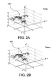
- FIG. 2A is an example of a frame containing 3D point cloud data 200-i, which is obtained from a sensor 102-i in FIG. 1 .
- FIG. 2B is an example of a frame of 3D point cloud data 200-j, which is obtained from a sensor 102-j in FIG. 1 .
- the frames of 3D point cloud data in FIGS. 2A and 2B shall be respectively referred to herein as "frame i" and "frame j". It can be observed in FIGS.
- the 3D point cloud data 200-i, 200-j each define the location of a set of data points in a volume, each of which can be defined in a three-dimensional space by a location on an x, y, and z axis.
- the measurements performed by the sensor 102-I, 102-j define the x, y, z location of each data point.
- the sensor(s) 102-i, 102-j can have respectively different locations and orientation.
- the location and orientation of the sensors 102-i, 102-j is sometimes referred to as the pose of such sensors.
- the sensor 102-i can be said to have a pose that is defined by pose parameters at the moment that the 3D point cloud data 200-i comprising frame i was acquired.
- a sequence of frames of 3D point cloud data can only be registered if at least a portion of the 3D point cloud data in frame i and frame j is obtained based on common subject matter (i.e. the same physical or geographic area). Accordingly, at least a portion of frames i and j will generally include data from a common geographic area. For example, it is generally preferable for at least about 1/3 common of each frame to contain data for a common geographic area, although the invention is not limited in this regard. Further, it should be understood that the data contained in frames i and j need not be obtained within a short period of time of each other.
- the registration process described herein can be used for 3D point cloud data contained in frames i and j that have been acquired weeks, months, or even years apart.
- Step 302 and 304 involve obtaining 3D point cloud data 200-i, 200-j comprising frame i and j, where frame j is designated as a reference frame. This step is performed using the techniques described above in relation to FIGS. 1 and 2 .
- the exact method used for obtaining the 3D point cloud data 200-i, 200-j for each frame is not critical. All that is necessary is that the resulting frames contain data defining the location of each of a plurality of points in a volume, and that each point is defined by a set of coordinates corresponding to an x, y, and z axis.
- step 600 a determination is made as to whether coarse registration has been completed for all n frames in a sequence of frames which are to be registered. If not, then the value of j is incremented in step 602 and the process returns to step 304 to acquire the point cloud data for the next frame j. Thereafter, steps 304, 400, 500, 600 and 602 are repeated until registration is completed for all n frames. At that point, the process will proceed to step 700.
- step 700 all coarsely adjusted frame pairs from the coarse registration process in steps 400, 500 and 600 are processed simultaneously to provide a more precise registration.
- Step 700 involves simultaneously calculating global values of R j T j for all n frames of 3D point cloud data, where R j is the rotation vector necessary for aligning or registering all points in each frame j to frame i, and T j is the translation vector for aligning or registering all points in frame j with frame i.
- Step 800 is the final step in the registration process.
- the calculated values for R j and T j for each frame as calculated in step 700 are used to translate the point cloud data from each frame to a common coordinate system.
- the common coordinate system can be the coordinate system of frame i.
- the registration process is complete for all frames in the sequence of frames.
- a sensor may collect 25 to 40 consecutive frames consisting of 3D measurements during a collection interval. All of these frames can be aligned with the process described in FIG. 3 .
- the process thereafter terminates in step 900 and the aggregated data from a sequence of frames can be displayed.
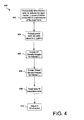
- the coarse x, y registration in step 400 can include a plurality of steps, beginning with step 402.
- each frame i, j is sliced horizontally (i.e., parallel to the plane defined by the x, y axes in FIG. 2 ) so that a portion of the total volume comprising the 3D point clouds 200-i, 200-j is selected.
- FIGS. 2C and 2D show planes 201, 202 forming sub-volume 203 in frames i, j.
- This sub-volume 203 is advantageously selected to be a volume that is believed likely to contain a target of interest and which excludes extraneous data which is not of interest.
- the sub-volume of the frame that is selected can include 3D point cloud data points corresponding to locations which are slightly above the surface of the ground level and extending to some predetermined altitude or height above ground level.
- the invention is not limited in this regard.
- step 404 the various data points that comprise the 3D point cloud 200-i, 200-j are projected to their respective x, y plane from their location in the point clouds. Stated another way, the x and y values of the data points in each frame remain the same, while the z value for each of the data points is set to zero.
- the result of step 404 is to convert each frame i, j comprised of the 3D point cloud data to a 2 dimensional frame in the x, y plane (XY frame).
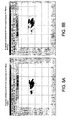
- FIG. 8A shows a projection to the XY plane of selected 3D point cloud data for frame i.
- FIG. 8B shows a projection to the XY plane of selected 3D point cloud data for frame j.
- the selected 3D point cloud data will in each case be the 3D point cloud data set selected in step 402.
- the projection of the 3D point cloud data to the XY plane for frames i and j is used to generate XY density images.
- the XY density images are created by using a window of size 5*voxelsize x 5*voxelsize.
- a voxel is a cube of scene data.
- the term "voxelsize" refers to the length of an edge of a single cubic voxel. For instance, a single voxel can have a size of (0.2 m) 3 based upon the LIDAR sensor resolution.
- the voxelsize*numvoxels (minus any filter edge effects) will equal the width of the density image,
- numvoxel refers to the number of voxels that are aligned in a direction corresponding to a width dimension of the density image.
- the width of the density image is very close to the width of 2D XY projection image after partial voxels and edge effects are removed.
- FIG. 9A shows an XY density image obtained from the XY projection of 3D point cloud data for frame i.
- FIG. 9B shows an XY density image obtained from the XY projection of point cloud data for frame j
- the purpose of the XY density images as described herein is to allow a subsequently applied filtering process to find edge content of the 2D shapes that will be registered. It should be noted that the approach described herein, involving filtering of a density image, is the preferred method for registration of for certain types of objects appearing in an image. In particular, this process works well for objects which are out in the open (i.e. not occluded or only minimally occluded) since it is simpler to apply computationally, versus an eigenmetric method. Based on the limited number of data points within each frame for objects that are heavily occluded, one skilled in the art might anticipate that this approach would not work with more heavily occluded objects.
- the registration technique has also been found to work unexpectedly well for objects under tree canopies. If the slice of data samples from a 3D image is carefully selected, enough shape content is available to perform the correlation and therefore complete the coarse registration of the 'incomplete' frames as described below.
- the slice of data points is preferably selected in such instances so as to include only data points between ground level to just under the lower tree limbs.
- step 406 the process continues with one or more filtering steps to create a filtered XY density image i and a filtered XY density image j respectively from the XY density image for frame i and the XY density image for frame j.
- step 406 includes (1) performing median filtering of the XY density images i, j, and (2) performing Sobel edge filtering of the median filter XY density images i, j.
- the median filter step is performed primarily to reduce noise in the XY density images i, j.
- Median filters are well known in the art. Accordingly, the process will not be described here in detail. In general, however, median filtering involves selection of a filter mask that is a certain number of pixels in height and width. The exact size of the mask can vary according to the particular application. In the present case, a filter mask having a size of 5 pixels high x 5 pixels wide has been found to provide suitable results. However, the invention is not limited in this regard. In practice, the mask is slid over the image and the center pixel contained within the mask is examined to determine if it has similar values as compared to its neighboring pixels. If not, this is often an indication that the particular pixel has been corrupted by noise.
- the median filter will replace the center pixel value with the median of the remaining pixels values under the mask.
- the median is calculated by first sorting all the pixel values under the mask into numerical order and then replacing the pixel being considered with the middle pixel value.
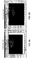
- FIG. 10A shows an XY density image for frame j before median filtering.
- FIG. 10B shows an XY density image for frame j after median filtering.
- the preparation of the filtered density images also involves edge filtering.
- edge filtering For the purpose of aligning two images, it can be helpful to identify the edges of objects contained in the image. For example, detecting the edges of objects forming an image will substantially reduce the total amount of data contained in the image. Edge detection preserves the important structural properties of an image but will remove information which is not generally useful for purposes of image alignment. Accordingly, it is advantageous to perform edge filtering on the XY density images after median filtering has been performed.
- edge generally refers to areas within a two-dimensional image where there exist strong intensity contrasts. In such areas, there is usually a rapid variation in intensity as between adjacent pixels.
- edge filtering can include any technique now known, or which is discovered in the future, which can be used for detecting or emphasizing edges within an image.
- edge filtering in the present invention can be carried out using a conventional Sobel filter.
- a Sobel operator is used to determine a 2-D spatial gradient measurement on an image.
- Conventional techniques for Sobel filter processing are well known. Accordingly, the Sobel filtering technique will not be described here in great detail.
- a first convolution mask 3 pixels high and 3 pixels wide is used for determining a gradient in the x-direction.
- a second convolution mask of the same size is used for determining a gradient in the ⁇ -direction.
- each of the first and second convolution masks will be much smaller than the actual XY density image.
- the masks are each slid over the image, manipulating one 3x3 group of pixels at a time in accordance with the Sobel operator.
- the first convolution mask highlights the edges in a first direction while the second convolution mask highlights the edges in a second direction, transverse to the first direction.
- the term "highlight" can refer to any image or data enhancement that allows edges of point clouds to be more clearly defined.
- the result of the process is edges that are highlighted in directions aligned with both the x and y axis.
- FIG. 11A shows the XY density image after median filtering, but before Sobel filtering.
- FIG. 11B shows the XY density image after Sobel filtering.
- the filtered XY density image is shown in FIG. 11B , which includes the median filtering and the edge enhancement effect resulting from the Sobel filtering.
- an XY translation error is determined.
- the XY translation error is a shift or offset in the x, y plane which exists as between the image data represented in the filtered XY density image i and the image data represented by the filtered XY density image j.
- the XY translation error can be defined by a vector which identifies the direction and distance of the shift or offset as between the two filtered XY density images i, j.
- One method for determining the XY translation error is by performing a cross-correlation of the filtered density images i, j. It is well known in the art that the cross-correlation of two images is a standard approach which can be used for identifying similarities as between two images. If two images contain at least some common subject matter, the cross-correlation process will generally result in a peak in the correlation value at a location which corresponds to the actual XY translation error.
- a normalized correlation is generally only usable for rotational variations of two or three degrees.
- the 2D projections in the case of the preferred mode for objects in the open
- the 3D volumes in the case of the preferred mode for occluded objects under trees
- This problem can be addressed by collecting supporting data to allow for adjustment of the orientation of the data.
- a correlation process which is invariant to rotation is preferred. Rotationally invariant correlation processes are known in the art.
- the normalized cross-correlation for the filtered density images i, j we calculate the normalized cross-correlation for the filtered density images i, j.
- the peak of the cross-correlation surface plot occurs where the XY filtered density images for frame i and frame j are best correlated.
- the correlation peak location will identify a shift in the x, y plane as between frames i and j.
- the actual XY translation error vector is easily determined from the peak location. Simply it is the delta x and delta y between the two frames calculated from the center of the frames.
- the adjustments are applied while holding the reference frame constant. If there are only two frames, either can be considered the reference. For a sequence of frames (as is collected for objects located under a tree canopy, for instance) the center frame works best as the reference frame.
- the correlation process described herein with respect to step 408 can include a Normalized Cross Correlation (NCC) process performed with respect to filtered XY density images i, and j.
- NCC Normalized Cross Correlation
- the cross-correlation of two images i and j is defined as the product: ⁇ p i ⁇ w i ⁇ p j ⁇ w j p i ⁇ p j where pi is the pixel index running over the domain of interest w i in the filtered XY density image i, and similarly p j a running 2-dimensional index over the domain of interest w j in the XY density image j.
- the cross-correlation product denoted as ⁇ can be defined by various different functions, depending on the purpose of the cross-correlation.
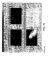
- FIG. 12 is a composite set of screen images showing the filtered density image obtained from frame i, the filtered density image obtained from frame j, and a correlation surface obtained by performing a normalized cross-correlation on these filtered density images.
- the correlation surface includes a correlation peak, which is identified in the figure.
- a different approach can be used in step 408 in place of the NCC process to determine the XY translation error.
- the NCC can be replaced by a similarity metric which is rotationally invariant.
- any suitable similarity metric can be used for this purpose, provided that it is rotationally invariant, or is at least less sensitive to rotational variations as compared to the NCC process.
- a rotationally invariant similarity metric can be particularly advantageous in those situations where the pose of sensor 102-i was rotated with respect to sensor 102-j when the frames i and j were obtained.
- the result will be some translation error vector in the x, y plane which defines the XY translation error as between the filtered density image i and the filtered density image j.
- the process can continue on to step 410.
- the translation error vector is used to provide a coarse adjustment of the position of the data points in the frames i and j so that they are approximately aligned with each other, at least with respect to their position in the x, y plane.
- step 500 where the frames i, j after coarse alignment in the x, y plane is complete, are passed on for coarse alignment in the z direction.
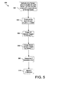
- the coarse z registration in step 500 can also include a plurality of steps 502, 504, 506, 508 and 510. These steps are generally similar to steps 402, 404, 406, 408 410 in FIG. 4 , except that in FIG. 5 , the coarse registration is performed for the z direction instead of in the x, y plane.
- each frame i, j is sliced vertically (i.e., parallel to the plane defined by the x, z axes) so that a portion of the total volume comprising the 3D point cloud 200-i, 200-j is selected.
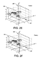
- FIGS. 2E and 2F show planes 203, 204 forming sub-volume 205 in frames i, j.
- This sub-volume 205 is advantageously selected to be a volume that is believed likely to contain a target of interest.
- the sub-volume 205 of the frame i, j that is selected can include 3D point cloud data points corresponding to locations which are spaced a predetermined distance on either side of the plane defined by the x, z axes in FIG. 2 .
- the invention is not limited in this regard. In other circumstances it can be desirable to choose a sub-volume that extends a greater or lesser distance away from the plane defined by the x, z axes.
- step 504 the method continues by projecting the various data points that comprise the 3D point cloud 200-i, 200-j onto the x, z plane from their location in the point cloud. Stated another way, the x and z values of the data points remain the same, while the y value for each of the data points is set to zero.
- the result of step 504 is to convert each frame i, j comprising the 3D point cloud data to a 2 dimensional frame in the x, z plane (XZ frame).
- FIG. 13A is a projection to the x, z plane of the selected 3D point cloud data from frame i.
- FIG. 13B is a projection to the x, z plane of the selected 3D point cloud data from frame j.
- step 505 the projection of the 3D point cloud data to the XZ plane for frames i and j is used to generate XZ density images.
- the XZ density images are generated in a manner similar to the one described above with regard to the XY density mages, except that in this instance the value of Y is set to zero. In this way, an XZ density image for frame i is obtained, and an XZ density image for frame j is obtained.
- step 506 the process continues by creating filtered XZ density image i and filtered XZ density image j. These filtered XZ density images are respectively created from the XZ density image for frame i and the XZ density image for frame j. Creation of the filtered XZ density images i, j in step 506 actually involves at least two steps. Briefly, step 506 includes (1) performing median filtering of the XZ density images i, j, and (2) performing Sobel edge filtering of the median filter XZ density images i, j. These intermediate steps were described above in detail with respect to FIG. 4 . Accordingly, that description will not be repeated here.
- a coarse determination of the Z translation error is determined.
- the Z translation error is a shift or offset in the z axis direction which exists as between the image data represented in the filtered XZ density image i and the image data represented by the filtered XZ density image j.
- the Z translation error can be defined by a vector which identifies the z direction shift or offset as between the two filtered XZ density images i, j.
- One method for determining the Z translation error is by performing an NCC operation on the filtered XZ density images i, j in a manner similar to that previously described with respect to step 408.
- other types of similarity metrics can also be used. In this regard, it will be appreciated that similarity metrics that are rotationally invariant can be advantageous, particularly in those situations where the pose of sensor 102-i was rotated with respect to sensor 102-j when the frames i and j were obtained.
- a fine registration process is performed in step 700 following the coarse registration process in steps 400, 500 and 600.
- steps 400, 500 and 600 there are a variety of conventional methods that can be used to perform fine registration for 3D point cloud frames i, j, particularly after the coarse registration process described above has been completed. Any such fine registration process can be used with the present invention.
- a simple iterative approach can be used which involves a global optimization routine. Such an approach can involve finding x, y and z transformations that best explain the positional relationships between the data points in frame i and frame j after coarse registration has been completed.
- the optimization routine can iterate between finding the various positional transformations of data points that explain the correspondence of points in the frames i, j, and then finding the closest points given a particular iteration of a positional transformation.
- Various mathematical techniques that are known in the art can be applied to this problem. For example, one such mathematical technique that can be applied to this problem is described in a paper by J. Williams and M. Bennamoun entitled “Simultaneous Registration of Multiple Point Sets Using Orthonormal Matrices" Proc., IEEE Int. Conf. on Acoustics, Speech and Signal Processing (ICASSP '00), the disclosure of which is incorporated herein by reference.
- fine registration step 700 can include a number of steps, beginning with step 710.
- frame i and frame j are each subdivided into a plurality of sub-volumes.
- individual sub-volumes can be selected that are considerably smaller in total volume as compared to the entire volume of frame i and frame j.
- the volume comprising each of frame i and frame j can be divided into 16 sub-volumes. The exact size of the sub-volume can be selected based on the anticipated size of selected objects appearing within the scene.
- step 720 the process continues by performing an eigen analysis to determine a set of eigen values ⁇ 1 , ⁇ 2 , and ⁇ 3 for each of the sub-volumes defined in step 710.
- an eigen analysis can be used to provide a summary of a data structure represented by a symmetrical matrix.
- the symmetrical matrix used to calculate each set of eigen values is selected to be the point cloud data contained in each of the sub-volumes.
- Each of the point cloud data points in each sub-volume are defined by a x,y and z value.
- an ellipsoid can be drawn around the data, and the ellipsoid can be defined by the three 3 eigen values, namely ⁇ 1 , ⁇ 2 , and ⁇ 3 .
- the first eigenvalue is always the largest and the third is always the smallest.
- the eigenmetrics are calculated using the table in FIG. 6 to determine the structure of the point cloud in that sub-volume.
- the coarse alignment previously performed for each of the frames of 3D point cloud data is sufficient such that corresponding sub-volumes from each frame can be expected to contain data points associated with corresponding structure or objects contained in a scene.
- eigen values are particularly useful for characterizing or summarizing a data structure that is represented by a symmetrical matrix.
- the eigen values ⁇ 1 , ⁇ 2 , and ⁇ 3 are used for computation of a series of metrics which are useful for providing a measure of the shape formed by a 3D point cloud within a sub-volume.
- the table in FIG. 6 identifies three metrics that can be computed and shows how they can be used for identifying lines, planes, curves, and blob-like objects.
- a blob-like point cloud can be understood to be a three dimensional ball or mass having an amorphous shape. Accordingly, blob-like point clouds as referred to herein generally do not include point clouds which form a straight line, a curved line, or a plane.
- step 730 the results of the eigen analysis and the table in FIG. 6 are used for identifying qualifying sub-volumes of frame i, j which can be most advantageously used for the fine registration process.
- qualifying sub-volumes refers to those sub-volumes defined in step 710 that the eigen metrics indicate contain a blob-like point cloud structure. It can be advantageous to further limit qualifying sub-volumes to those that include a sufficient amount of data or content. For example, qualifying sub-volumes can be limited to those with at least a predetermined number of data points contained therein.
- This process is performed in step 730 for a plurality of scene pairs comprising both adjacent and non-adjacent scenes represented by a set of frames.
- scene pairs can comprise frames 1, 2; 1, 3; 1, 4; 2, 3; 2, 4; 2, 5 and so on, where consecutively numbered frames are adjacent, and non-consecutively numbered frames are not adjacent.
- step 740 the process continues by identifying, for each scene pair in the data set, corresponding pairs of data points that are contained within the qualifying sub-volumes. This step is accomplished by finding data points in a qualifying sub-volume of one frame (e.g. frame j), that most closely match the position or location of data points from the qualifying sub-volume of the other frame (e.g. frame i). The raw data points from the qualifying sub-volumes are used to find correspondence between frame pairs. Point correspondence between frame pairs can be found using a K-D tree search method. This method, which is known in the art, is sometimes referred to as a nearest neighbor search method.
- the optimization routine can involve a simultaneous perturbation stochastic approximation (SPSA).
- SPSA simultaneous perturbation stochastic approximation
- Other optimization methods which can be used include the Nelder Mead Simplex method, the Least-Squares Fit method, and the Quasi-Newton method.
- the SPSA method is preferred for performing the optimization described herein.
- the present invention may be embodied as a data processing system or a computer program product. Accordingly, the present invention may take the form of an entirely hardware embodiment, an entirely software embodiment or an embodiment combining software and hardware aspects.
- the present invention may also take the form of a computer program product on a computer-usable storage medium having computer-usable program code embodied in the medium. Any suitable computer useable medium may be used, such as RAM, a disk driver, CD-ROM, hard disk, a magnetic storage device, and/or any other form of program bulk storage.
- Computer program code for carrying out the present invention may be written in Java®, C++, or any other object orientated programming language. However, the computer programming code may also be written in conventional procedural programming languages, such as "C" programming language. The computer programming code may be written in a visually oriented programming language, such as VisualBasic.
Claims (11)
- Procédé de repérage d'une pluralité de trames de données de nuage de points tridimensionnel (3D) concernant une cible d'intérêt, comprenant :l'acquisition d'au moins une première trame et une deuxième trame, contenant chacune des données de nuage de points 3D collectées pour un objet sélectionné ;la création d'une image en densité pour chacune de ladite première trame et de ladite deuxième trame respectivement (a) en projetant lesdites données de nuage de points 3D de chacune de ladite première trame et de ladite deuxième trame sur un plan bidimensionnel (2D) de manière à obtenir une trame 2D de points de données d'image 2D, et (b) en faisant passer une fenêtre sur ladite trame 2D desdits points de données d'image 2D pour déterminer une pluralité de valeurs d'image en densité, chacune définie par le nombre de points de données d'image 2D dans ladite fenêtre ;l'utilisation desdites images en densité obtenues à partir de ladite première trame et de ladite deuxième trame pour déterminer au moins un vecteur de translation ;l'exécution d'un repérage grossier desdites données de nuage de points 3D dans au moins l'un d'un plan XY et d'un plan Z en utilisant ledit au moins un vecteur de translation ;dans lequel ledit plan XY est défini par une pluralité de points ayant des valeurs z communes dans un système de coordonnées cartésiennes défini par des axes x, y et z, et ledit plan Z est défini par une pluralité de points dans un plan qui est normal audit plan XY.
- Procédé selon la revendication 1, comprenant en outre la sélection exclusive pour repérage d'un sous-volume desdites données de nuage de points 3D à partir de chaque trame, lequel sous-volume inclut moins d'un volume total desdites données de nuage de points 3D.
- Procédé selon la revendication 1, comprenant en outre la sélection desdites images en densité pour chacune de ladite première trame et de ladite deuxième trame pour être des images en densité XY en fixant à zéro une valeur de coordonnée z de chaque point de données dans un nuage de points 3D contenu dans lesdites première et deuxième trames.
- Procédé selon la revendication 1, comprenant en outre la sélection desdites images en densité pour ladite première trame et ladite deuxième trame pour être des images en densité XY en fixant à zéro une valeur de coordonnée y de chaque point de données dans un nuage de points 3D contenu dans lesdites première et deuxième trames.
- Procédé selon la revendication 1, comprenant en outre le filtrage de chacune desdites images en densité pour obtenir une image en densité filtrée pour chacune de ladite première trame et de ladite deuxième trame, avant la détermination dudit vecteur de translation.
- Procédé selon la revendication 5, dans lequel l'étape de détermination dudit au moins un vecteur de translation comprend en outre l'exécution d'une corrélation croisée de ladite image en densité filtrée obtenue à partir de ladite première trame et de ladite image en densité filtrée obtenue à partir de ladite deuxième trame.
- Procédé selon la revendication 6, comprenant en outre la détermination dudit au moins un vecteur de translation sur la base d'une valeur de pic résultant de la corrélation croisée de ladite image en densité filtrée à partir de ladite première trame et de ladite image en densité filtrée à partir de ladite deuxième trame.
- Procédé selon la revendication 1, comprenant en outre l'exécution d'un repérage grossier desdites données de nuage de points 3D à partir de ladite première trame et de ladite deuxième trame à la fois dans ledit plan XY et dans un sens de l'axe Z.
- Procédé selon la revendication 8, comprenant en outre l'exécution d'un processus de repérage fin sur lesdites données de nuage de points 3D à partir de ladite première trame et de ladite deuxième trame.
- Procédé selon la revendication 9, dans lequel ledit processus de repérage fin comprend en outre la définition d'une pluralité de sous-volumes au sein de chacune desdites première et deuxième trames.
- Procédé selon la revendication 10, dans lequel ledit processus de repérage fin comprend en outre l'identification d'un ou plusieurs sous-volumes qualifiants parmi lesdits sous-volumes qui inclut/incluent des agencements sélectionnés de données de nuage de points 3D.
Applications Claiming Priority (2)
| Application Number | Priority Date | Filing Date | Title |
|---|---|---|---|
| US12/046,862 US20090232388A1 (en) | 2008-03-12 | 2008-03-12 | Registration of 3d point cloud data by creation of filtered density images |
| PCT/US2009/034857 WO2009114254A1 (fr) | 2008-03-12 | 2009-02-23 | Alignement de données de nuages de points 3d par création d’images de densité filtrée |
Publications (2)
| Publication Number | Publication Date |
|---|---|
| EP2272045A1 EP2272045A1 (fr) | 2011-01-12 |
| EP2272045B1 true EP2272045B1 (fr) | 2011-07-13 |
Family
ID=40591969
Family Applications (1)
| Application Number | Title | Priority Date | Filing Date |
|---|---|---|---|
| EP09718697A Not-in-force EP2272045B1 (fr) | 2008-03-12 | 2009-02-23 | Alignement de données de nuages de points 3d par création d images de densité filtrée |
Country Status (7)
| Country | Link |
|---|---|
| US (1) | US20090232388A1 (fr) |
| EP (1) | EP2272045B1 (fr) |
| JP (1) | JP4926281B2 (fr) |
| AT (1) | ATE516561T1 (fr) |
| CA (1) | CA2716880A1 (fr) |
| TW (1) | TW200945245A (fr) |
| WO (1) | WO2009114254A1 (fr) |
Cited By (1)
| Publication number | Priority date | Publication date | Assignee | Title |
|---|---|---|---|---|
| EP4124890A1 (fr) | 2021-07-28 | 2023-02-01 | Continental Autonomous Mobility Germany GmbH | Nuage de points lidar densifié |
Families Citing this family (58)
| Publication number | Priority date | Publication date | Assignee | Title |
|---|---|---|---|---|
| US7983835B2 (en) | 2004-11-03 | 2011-07-19 | Lagassey Paul J | Modular intelligent transportation system |
| DE102007034950B4 (de) * | 2007-07-26 | 2009-10-29 | Siemens Ag | Verfahren zur selektiven sicherheitstechnischen Überwachung von Flugstrom-Vergasungsreaktoren |
| US20090232355A1 (en) * | 2008-03-12 | 2009-09-17 | Harris Corporation | Registration of 3d point cloud data using eigenanalysis |
| US20090231327A1 (en) * | 2008-03-12 | 2009-09-17 | Harris Corporation | Method for visualization of point cloud data |
| US8224097B2 (en) * | 2008-06-12 | 2012-07-17 | Sri International | Building segmentation for densely built urban regions using aerial LIDAR data |
| US8155452B2 (en) * | 2008-10-08 | 2012-04-10 | Harris Corporation | Image registration using rotation tolerant correlation method |
| US8290305B2 (en) * | 2009-02-13 | 2012-10-16 | Harris Corporation | Registration of 3D point cloud data to 2D electro-optical image data |
| US8179393B2 (en) | 2009-02-13 | 2012-05-15 | Harris Corporation | Fusion of a 2D electro-optical image and 3D point cloud data for scene interpretation and registration performance assessment |
| US20100208981A1 (en) * | 2009-02-13 | 2010-08-19 | Harris Corporation | Method for visualization of point cloud data based on scene content |
| CA2687913A1 (fr) * | 2009-03-10 | 2010-09-10 | Her Majesty The Queen In Right Of Canada, As Represented By The Minister Of Industry Through The Communications Research Centre Canada | Estimation des relations inter-images a partir de correspondances de points inter-images |
| US20110115812A1 (en) * | 2009-11-13 | 2011-05-19 | Harris Corporation | Method for colorization of point cloud data based on radiometric imagery |
| TWI397015B (zh) * | 2009-11-27 | 2013-05-21 | Inst Information Industry | 三維影像分析系統、處理裝置及其方法 |
| US20110200249A1 (en) * | 2010-02-17 | 2011-08-18 | Harris Corporation | Surface detection in images based on spatial data |
| US9053562B1 (en) | 2010-06-24 | 2015-06-09 | Gregory S. Rabin | Two dimensional to three dimensional moving image converter |
| JP5875120B2 (ja) * | 2010-07-30 | 2016-03-02 | 学校法人 芝浦工業大学 | 他視点閉曲面画素値補正装置、他視点閉曲面画素値補正方法、利用者位置情報出力装置、利用者位置情報出力方法 |
| US8913784B2 (en) | 2011-08-29 | 2014-12-16 | Raytheon Company | Noise reduction in light detection and ranging based imaging |
| CN103093450B (zh) * | 2011-10-31 | 2017-03-08 | 鸿富锦精密工业(深圳)有限公司 | 产品局部对齐方法及系统 |
| KR102029055B1 (ko) * | 2013-02-08 | 2019-10-07 | 삼성전자주식회사 | 고차원 데이터의 시각화 방법 및 장치 |
| US9992021B1 (en) | 2013-03-14 | 2018-06-05 | GoTenna, Inc. | System and method for private and point-to-point communication between computing devices |
| KR101534927B1 (ko) * | 2013-10-08 | 2015-07-07 | 현대자동차주식회사 | 차량 인지 장치 및 방법 |
| DE102014104712B4 (de) * | 2014-04-02 | 2020-07-30 | Faro Technologies, Inc. | Registrierung einer in Cluster zerfallenden Szene mit visualisierten Clustern |
| DE102014104713A1 (de) | 2014-04-02 | 2015-10-08 | Faro Technologies, Inc. | Registrierung einer in Cluster zerfallenden Szene mit Paaren von Scans |
| DE102014110992A1 (de) | 2014-08-01 | 2016-02-04 | Faro Technologies Inc. | Registrierung einer in Cluster zerfallenden Szene mit Standortverfolgung |
| CN104217458B (zh) * | 2014-08-22 | 2017-02-15 | 长沙中科院文化创意与科技产业研究院 | 一种三维点云的快速配准方法 |
| CN105389774B (zh) * | 2014-09-05 | 2019-03-01 | 华为技术有限公司 | 对齐图像的方法和装置 |
| US10192283B2 (en) | 2014-12-22 | 2019-01-29 | Cognex Corporation | System and method for determining clutter in an acquired image |
| US9934590B1 (en) * | 2015-06-25 | 2018-04-03 | The United States Of America As Represented By The Secretary Of The Air Force | Tchebichef moment shape descriptor for partial point cloud characterization |
| US10452949B2 (en) | 2015-11-12 | 2019-10-22 | Cognex Corporation | System and method for scoring clutter for use in 3D point cloud matching in a vision system |
| WO2017132636A1 (fr) | 2016-01-29 | 2017-08-03 | Pointivo, Inc. | Systèmes et procédés d'extraction d'informations concernant des objets à partir d'informations de scène |
| US10482681B2 (en) | 2016-02-09 | 2019-11-19 | Intel Corporation | Recognition-based object segmentation of a 3-dimensional image |
| US10373380B2 (en) | 2016-02-18 | 2019-08-06 | Intel Corporation | 3-dimensional scene analysis for augmented reality operations |
| GB2550567A (en) | 2016-05-20 | 2017-11-29 | Nokia Technologies Oy | Point Cloud Matching Method |
| US10573018B2 (en) * | 2016-07-13 | 2020-02-25 | Intel Corporation | Three dimensional scene reconstruction based on contextual analysis |
| US11397088B2 (en) * | 2016-09-09 | 2022-07-26 | Nanyang Technological University | Simultaneous localization and mapping methods and apparatus |
| GB2559157A (en) * | 2017-01-27 | 2018-08-01 | Ucl Business Plc | Apparatus, method and system for alignment of 3D datasets |
| GB201701363D0 (en) * | 2017-01-27 | 2017-03-15 | Secr Defence | Apparatus and method for registering recorded images |
| US11043026B1 (en) | 2017-01-28 | 2021-06-22 | Pointivo, Inc. | Systems and methods for processing 2D/3D data for structures of interest in a scene and wireframes generated therefrom |
| CN108556365B (zh) * | 2018-03-12 | 2021-06-22 | 中南大学 | 一种快速成型机的复合填充优化方法及系统 |
| US11562505B2 (en) | 2018-03-25 | 2023-01-24 | Cognex Corporation | System and method for representing and displaying color accuracy in pattern matching by a vision system |
| CN108876862B (zh) * | 2018-07-13 | 2021-12-07 | 北京控制工程研究所 | 一种非合作目标点云位置姿态计算方法 |
| CN109117825B (zh) | 2018-09-04 | 2020-01-17 | 百度在线网络技术(北京)有限公司 | 车道线处理方法和装置 |
| CN109255181B (zh) | 2018-09-07 | 2019-12-24 | 百度在线网络技术(北京)有限公司 | 一种基于多模型的障碍物分布仿真方法、装置以及终端 |
| CN109143242B (zh) | 2018-09-07 | 2020-04-14 | 百度在线网络技术(北京)有限公司 | 障碍物绝对速度估计方法、系统、计算机设备和存储介质 |
| CN109146898B (zh) | 2018-09-07 | 2020-07-24 | 百度在线网络技术(北京)有限公司 | 一种仿真数据量增强方法、装置以及终端 |
| CN109215136B (zh) * | 2018-09-07 | 2020-03-20 | 百度在线网络技术(北京)有限公司 | 一种真实数据增强方法、装置以及终端 |
| CN110375659B (zh) | 2018-09-11 | 2021-07-27 | 百度在线网络技术(北京)有限公司 | 检测障碍物高度的方法、装置、设备及存储介质 |
| CN109165629B (zh) | 2018-09-13 | 2019-08-23 | 百度在线网络技术(北京)有限公司 | 多焦距视觉障碍物感知方法、装置、设备及存储介质 |
| EP3869461B1 (fr) * | 2018-10-18 | 2022-10-05 | Fujitsu Limited | Procédé de calcul, programme de calcul, et dispositif de traitement d'informations |
| CN109509226B (zh) * | 2018-11-27 | 2023-03-28 | 广东工业大学 | 三维点云数据配准方法、装置、设备及可读存储介质 |
| CN109703568B (zh) | 2019-02-19 | 2020-08-18 | 百度在线网络技术(北京)有限公司 | 自动驾驶车辆行驶策略实时学习的方法、装置和服务器 |
| CN109712421B (zh) | 2019-02-22 | 2021-06-04 | 百度在线网络技术(北京)有限公司 | 自动驾驶车辆的速度规划方法、装置和存储介质 |
| CN111753858A (zh) * | 2019-03-26 | 2020-10-09 | 理光软件研究所(北京)有限公司 | 一种点云匹配方法、装置和重定位系统 |
| JP7283005B2 (ja) * | 2019-03-28 | 2023-05-30 | 株式会社トプコン | 点群データ処理方法および点群データ処理装置 |
| CN112146564B (zh) * | 2019-06-28 | 2022-04-15 | 先临三维科技股份有限公司 | 三维扫描方法、装置、计算机设备和计算机可读存储介质 |
| CN110443837B (zh) * | 2019-07-03 | 2021-09-24 | 湖北省电力勘测设计院有限公司 | 一种直线特征约束下的城区机载激光点云与航空影像配准方法和系统 |
| US11074708B1 (en) * | 2020-01-06 | 2021-07-27 | Hand Held Products, Inc. | Dark parcel dimensioning |
| JP2023525534A (ja) * | 2020-05-11 | 2023-06-16 | コグネックス・コーポレイション | 3次元画像から外形を抽出する方法及び装置 |
| CN111899291A (zh) * | 2020-08-05 | 2020-11-06 | 深圳市数字城市工程研究中心 | 基于多源维度分解的城市点云从粗到精的自动配准方法 |
Family Cites Families (52)
| Publication number | Priority date | Publication date | Assignee | Title |
|---|---|---|---|---|
| US5247587A (en) * | 1988-07-15 | 1993-09-21 | Honda Giken Kogyo Kabushiki Kaisha | Peak data extracting device and a rotary motion recurrence formula computing device |
| FR2641099B1 (fr) * | 1988-12-22 | 1991-02-22 | Gen Electric Cgr | |
| US6418424B1 (en) * | 1991-12-23 | 2002-07-09 | Steven M. Hoffberg | Ergonomic man-machine interface incorporating adaptive pattern recognition based control system |
| US5901246A (en) * | 1995-06-06 | 1999-05-04 | Hoffberg; Steven M. | Ergonomic man-machine interface incorporating adaptive pattern recognition based control system |
| US6400996B1 (en) * | 1999-02-01 | 2002-06-04 | Steven M. Hoffberg | Adaptive pattern recognition based control system and method |
| US5875108A (en) * | 1991-12-23 | 1999-02-23 | Hoffberg; Steven M. | Ergonomic man-machine interface incorporating adaptive pattern recognition based control system |
| US6081750A (en) * | 1991-12-23 | 2000-06-27 | Hoffberg; Steven Mark | Ergonomic man-machine interface incorporating adaptive pattern recognition based control system |
| FR2701135B1 (fr) * | 1993-01-29 | 1995-03-10 | Commissariat Energie Atomique | Procédé de reconstruction d'images tridimensionnelles d'un objet évoluant. |
| US5495562A (en) * | 1993-04-12 | 1996-02-27 | Hughes Missile Systems Company | Electro-optical target and background simulation |
| JP3030485B2 (ja) * | 1994-03-17 | 2000-04-10 | 富士通株式会社 | 3次元形状抽出方法及び装置 |
| US5839440A (en) * | 1994-06-17 | 1998-11-24 | Siemens Corporate Research, Inc. | Three-dimensional image registration method for spiral CT angiography |
| US6405132B1 (en) * | 1997-10-22 | 2002-06-11 | Intelligent Technologies International, Inc. | Accident avoidance system |
| US6526352B1 (en) * | 2001-07-19 | 2003-02-25 | Intelligent Technologies International, Inc. | Method and arrangement for mapping a road |
| US5781146A (en) * | 1996-03-11 | 1998-07-14 | Imaging Accessories, Inc. | Automatic horizontal and vertical scanning radar with terrain display |
| US5988862A (en) * | 1996-04-24 | 1999-11-23 | Cyra Technologies, Inc. | Integrated system for quickly and accurately imaging and modeling three dimensional objects |
| US6420698B1 (en) * | 1997-04-24 | 2002-07-16 | Cyra Technologies, Inc. | Integrated system for quickly and accurately imaging and modeling three-dimensional objects |
| WO2000016250A1 (fr) * | 1998-09-17 | 2000-03-23 | The Catholic University Of America | Procede de decomposition/reduction de donnees permettant de visualiser les groupes/sous-groupes de donnees |
| US6448968B1 (en) * | 1999-01-29 | 2002-09-10 | Mitsubishi Electric Research Laboratories, Inc. | Method for rendering graphical objects represented as surface elements |
| JP3404675B2 (ja) * | 1999-03-19 | 2003-05-12 | 日本電信電話株式会社 | 3次元断層画像読影方法、自動照合方法、及びその装置並びにそのプログラムを記録した記録媒体 |
| US6904163B1 (en) * | 1999-03-19 | 2005-06-07 | Nippon Telegraph And Telephone Corporation | Tomographic image reading method, automatic alignment method, apparatus and computer readable medium |
| US7206462B1 (en) * | 2000-03-17 | 2007-04-17 | The General Hospital Corporation | Method and system for the detection, comparison and volumetric quantification of pulmonary nodules on medical computed tomography scans |
| US7027642B2 (en) * | 2000-04-28 | 2006-04-11 | Orametrix, Inc. | Methods for registration of three-dimensional frames to create three-dimensional virtual models of objects |
| AU2001251606A1 (en) * | 2000-04-28 | 2001-11-12 | Orametirix, Inc. | Method and system for scanning a surface and generating a three-dimensional object |
| US6690820B2 (en) * | 2001-01-31 | 2004-02-10 | Magic Earth, Inc. | System and method for analyzing and imaging and enhanced three-dimensional volume data set using one or more attributes |
| AUPR301401A0 (en) * | 2001-02-09 | 2001-03-08 | Commonwealth Scientific And Industrial Research Organisation | Lidar system and method |
| JP3801870B2 (ja) * | 2001-02-16 | 2006-07-26 | 株式会社モノリス | 多変量空間処理装置 |
| AU2002257442A1 (en) * | 2001-05-14 | 2002-11-25 | Fadi Dornaika | Attentive panoramic visual sensor |
| JP4136404B2 (ja) * | 2002-03-13 | 2008-08-20 | オリンパス株式会社 | 画像間類似度算出装置、画像間類似度算出方法、及び、プログラム |
| US7098809B2 (en) * | 2003-02-18 | 2006-08-29 | Honeywell International, Inc. | Display methodology for encoding simultaneous absolute and relative altitude terrain data |
| US7242460B2 (en) * | 2003-04-18 | 2007-07-10 | Sarnoff Corporation | Method and apparatus for automatic registration and visualization of occluded targets using ladar data |
| US7298376B2 (en) * | 2003-07-28 | 2007-11-20 | Landmark Graphics Corporation | System and method for real-time co-rendering of multiple attributes |
| US7103399B2 (en) * | 2003-09-08 | 2006-09-05 | Vanderbilt University | Apparatus and methods of cortical surface registration and deformation tracking for patient-to-image alignment in relation to image-guided surgery |
| US7831087B2 (en) * | 2003-10-31 | 2010-11-09 | Hewlett-Packard Development Company, L.P. | Method for visual-based recognition of an object |
| CN101133431B (zh) * | 2005-02-03 | 2011-08-24 | 布拉科成像S.P.A.公司 | 能够减少物体运动造成的成像伪影的生物医学图像配准方法 |
| US7777761B2 (en) * | 2005-02-11 | 2010-08-17 | Deltasphere, Inc. | Method and apparatus for specifying and displaying measurements within a 3D rangefinder data set |
| US7477360B2 (en) * | 2005-02-11 | 2009-01-13 | Deltasphere, Inc. | Method and apparatus for displaying a 2D image data set combined with a 3D rangefinder data set |
| US7974461B2 (en) * | 2005-02-11 | 2011-07-05 | Deltasphere, Inc. | Method and apparatus for displaying a calculated geometric entity within one or more 3D rangefinder data sets |
| JP2007315777A (ja) * | 2006-05-23 | 2007-12-06 | Ditect:Kk | 三次元形状計測システム |
| US7822266B2 (en) * | 2006-06-02 | 2010-10-26 | Carnegie Mellon University | System and method for generating a terrain model for autonomous navigation in vegetation |
| JP5057734B2 (ja) * | 2006-09-25 | 2012-10-24 | 株式会社トプコン | 測量方法及び測量システム及び測量データ処理プログラム |
| US7990397B2 (en) * | 2006-10-13 | 2011-08-02 | Leica Geosystems Ag | Image-mapped point cloud with ability to accurately represent point coordinates |
| US7940279B2 (en) * | 2007-03-27 | 2011-05-10 | Utah State University | System and method for rendering of texel imagery |
| US8218905B2 (en) * | 2007-10-12 | 2012-07-10 | Claron Technology Inc. | Method, system and software product for providing efficient registration of 3D image data |
| US20090231327A1 (en) * | 2008-03-12 | 2009-09-17 | Harris Corporation | Method for visualization of point cloud data |
| US20090232355A1 (en) * | 2008-03-12 | 2009-09-17 | Harris Corporation | Registration of 3d point cloud data using eigenanalysis |
| US8155452B2 (en) * | 2008-10-08 | 2012-04-10 | Harris Corporation | Image registration using rotation tolerant correlation method |
| US8427505B2 (en) * | 2008-11-11 | 2013-04-23 | Harris Corporation | Geospatial modeling system for images and related methods |
| US8290305B2 (en) * | 2009-02-13 | 2012-10-16 | Harris Corporation | Registration of 3D point cloud data to 2D electro-optical image data |
| US20100208981A1 (en) * | 2009-02-13 | 2010-08-19 | Harris Corporation | Method for visualization of point cloud data based on scene content |
| US8179393B2 (en) * | 2009-02-13 | 2012-05-15 | Harris Corporation | Fusion of a 2D electro-optical image and 3D point cloud data for scene interpretation and registration performance assessment |
| US20110115812A1 (en) * | 2009-11-13 | 2011-05-19 | Harris Corporation | Method for colorization of point cloud data based on radiometric imagery |
| US20110200249A1 (en) * | 2010-02-17 | 2011-08-18 | Harris Corporation | Surface detection in images based on spatial data |
-
2008
- 2008-03-12 US US12/046,862 patent/US20090232388A1/en not_active Abandoned
-
2009
- 2009-02-23 EP EP09718697A patent/EP2272045B1/fr not_active Not-in-force
- 2009-02-23 AT AT09718697T patent/ATE516561T1/de not_active IP Right Cessation
- 2009-02-23 JP JP2010550724A patent/JP4926281B2/ja not_active Expired - Fee Related
- 2009-02-23 CA CA2716880A patent/CA2716880A1/fr not_active Abandoned
- 2009-02-23 WO PCT/US2009/034857 patent/WO2009114254A1/fr active Application Filing
- 2009-03-11 TW TW098107882A patent/TW200945245A/zh unknown
Cited By (1)
| Publication number | Priority date | Publication date | Assignee | Title |
|---|---|---|---|---|
| EP4124890A1 (fr) | 2021-07-28 | 2023-02-01 | Continental Autonomous Mobility Germany GmbH | Nuage de points lidar densifié |
Also Published As
| Publication number | Publication date |
|---|---|
| CA2716880A1 (fr) | 2009-09-17 |
| EP2272045A1 (fr) | 2011-01-12 |
| ATE516561T1 (de) | 2011-07-15 |
| JP4926281B2 (ja) | 2012-05-09 |
| JP2011513881A (ja) | 2011-04-28 |
| WO2009114254A1 (fr) | 2009-09-17 |
| US20090232388A1 (en) | 2009-09-17 |
| TW200945245A (en) | 2009-11-01 |
Similar Documents
| Publication | Publication Date | Title |
|---|---|---|
| EP2272045B1 (fr) | Alignement de données de nuages de points 3d par création d images de densité filtrée | |
| US20090232355A1 (en) | Registration of 3d point cloud data using eigenanalysis | |
| US8290305B2 (en) | Registration of 3D point cloud data to 2D electro-optical image data | |
| Behmann et al. | Calibration of hyperspectral close-range pushbroom cameras for plant phenotyping | |
| US7738687B2 (en) | Method of registration in a contraband detection system | |
| Gilliot et al. | Soil surface roughness measurement: A new fully automatic photogrammetric approach applied to agricultural bare fields | |
| Jaboyedoff et al. | New insight techniques to analyze rock-slope relief using DEM and 3Dimaging cloud points: COLTOP-3D software | |
| Brown | A survey of image registration techniques | |
| KR101489984B1 (ko) | 스테레오-영상 정합 및 변화 검출 시스템 및 방법 | |
| CN112712535B (zh) | 基于模拟困难样本的Mask-RCNN滑坡分割方法 | |
| JP2008292449A (ja) | 水中で対象物を検知し分類する自動目標識別システム | |
| EP2869094B1 (fr) | Systèmes et procédés d'imagerie stéréoscopique | |
| López et al. | An optimized approach for generating dense thermal point clouds from UAV-imagery | |
| CN110458876A (zh) | 基于sar-sift特征的多时相polsar图像配准方法 | |
| Bolkas et al. | Registration of multi-platform point clouds using edge detection for rockfall monitoring | |
| Tu et al. | Detecting facade damage on moderate damaged type from high-resolution oblique aerial images | |
| Wan et al. | A performance comparison of feature detectors for planetary rover mapping and localization | |
| Gallego et al. | A variational wave acquisition stereo system for the 3-d reconstruction of oceanic sea states | |
| Recio et al. | Potential evaluation of different types of images and their combination for the classification of gis objects cropland and grassland | |
| Tian et al. | Region based forest change detection from Cartosat-1 stereo imagery | |
| Agrafiotis et al. | The effect of pansharpening algorithms on the resulting orthoimagery | |
| Chen et al. | A novel building detection method using ZY-3 multi-angle imagery over urban areas | |
| Wu et al. | An evaluation of Deep Learning based stereo dense matching dataset shift from aerial images and a large scale stereo dataset | |
| Brunner et al. | Building height retrieval from airborne VHR SAR imagery based on an iterative simulation and matching procedure | |
| RU2673774C2 (ru) | Способ оценки структурных изменений образца материала в результате воздействия на образец |
Legal Events
| Date | Code | Title | Description |
|---|---|---|---|
| PUAI | Public reference made under article 153(3) epc to a published international application that has entered the european phase |
Free format text: ORIGINAL CODE: 0009012 |
|
| 17P | Request for examination filed |
Effective date: 20101012 |
|
| AK | Designated contracting states |
Kind code of ref document: A1 Designated state(s): AT BE BG CH CY CZ DE DK EE ES FI FR GB GR HR HU IE IS IT LI LT LU LV MC MK MT NL NO PL PT RO SE SI SK TR |
|
| AX | Request for extension of the european patent |
Extension state: AL BA RS |
|
| GRAP | Despatch of communication of intention to grant a patent |
Free format text: ORIGINAL CODE: EPIDOSNIGR1 |
|
| GRAS | Grant fee paid |
Free format text: ORIGINAL CODE: EPIDOSNIGR3 |
|
| GRAA | (expected) grant |
Free format text: ORIGINAL CODE: 0009210 |
|
| DAX | Request for extension of the european patent (deleted) | ||
| AK | Designated contracting states |
Kind code of ref document: B1 Designated state(s): AT BE BG CH CY CZ DE DK EE ES FI FR GB GR HR HU IE IS IT LI LT LU LV MC MK MT NL NO PL PT RO SE SI SK TR |
|
| REG | Reference to a national code |
Ref country code: GB Ref legal event code: FG4D |
|
| REG | Reference to a national code |
Ref country code: CH Ref legal event code: EP |
|
| REG | Reference to a national code |
Ref country code: IE Ref legal event code: FG4D |
|
| REG | Reference to a national code |
Ref country code: DE Ref legal event code: R096 Ref document number: 602009001813 Country of ref document: DE Effective date: 20110901 |
|
| REG | Reference to a national code |
Ref country code: NL Ref legal event code: VDEP Effective date: 20110713 |
|
| REG | Reference to a national code |
Ref country code: AT Ref legal event code: MK05 Ref document number: 516561 Country of ref document: AT Kind code of ref document: T Effective date: 20110713 |
|
| PG25 | Lapsed in a contracting state [announced via postgrant information from national office to epo] |
Ref country code: PT Free format text: LAPSE BECAUSE OF FAILURE TO SUBMIT A TRANSLATION OF THE DESCRIPTION OR TO PAY THE FEE WITHIN THE PRESCRIBED TIME-LIMIT Effective date: 20111114 Ref country code: FI Free format text: LAPSE BECAUSE OF FAILURE TO SUBMIT A TRANSLATION OF THE DESCRIPTION OR TO PAY THE FEE WITHIN THE PRESCRIBED TIME-LIMIT Effective date: 20110713 Ref country code: NL Free format text: LAPSE BECAUSE OF FAILURE TO SUBMIT A TRANSLATION OF THE DESCRIPTION OR TO PAY THE FEE WITHIN THE PRESCRIBED TIME-LIMIT Effective date: 20110713 Ref country code: HR Free format text: LAPSE BECAUSE OF FAILURE TO SUBMIT A TRANSLATION OF THE DESCRIPTION OR TO PAY THE FEE WITHIN THE PRESCRIBED TIME-LIMIT Effective date: 20110713 Ref country code: IS Free format text: LAPSE BECAUSE OF FAILURE TO SUBMIT A TRANSLATION OF THE DESCRIPTION OR TO PAY THE FEE WITHIN THE PRESCRIBED TIME-LIMIT Effective date: 20111113 Ref country code: BE Free format text: LAPSE BECAUSE OF FAILURE TO SUBMIT A TRANSLATION OF THE DESCRIPTION OR TO PAY THE FEE WITHIN THE PRESCRIBED TIME-LIMIT Effective date: 20110713 Ref country code: LT Free format text: LAPSE BECAUSE OF FAILURE TO SUBMIT A TRANSLATION OF THE DESCRIPTION OR TO PAY THE FEE WITHIN THE PRESCRIBED TIME-LIMIT Effective date: 20110713 Ref country code: NO Free format text: LAPSE BECAUSE OF FAILURE TO SUBMIT A TRANSLATION OF THE DESCRIPTION OR TO PAY THE FEE WITHIN THE PRESCRIBED TIME-LIMIT Effective date: 20111013 Ref country code: SE Free format text: LAPSE BECAUSE OF FAILURE TO SUBMIT A TRANSLATION OF THE DESCRIPTION OR TO PAY THE FEE WITHIN THE PRESCRIBED TIME-LIMIT Effective date: 20110713 |
|
| PG25 | Lapsed in a contracting state [announced via postgrant information from national office to epo] |
Ref country code: GR Free format text: LAPSE BECAUSE OF FAILURE TO SUBMIT A TRANSLATION OF THE DESCRIPTION OR TO PAY THE FEE WITHIN THE PRESCRIBED TIME-LIMIT Effective date: 20111014 Ref country code: AT Free format text: LAPSE BECAUSE OF FAILURE TO SUBMIT A TRANSLATION OF THE DESCRIPTION OR TO PAY THE FEE WITHIN THE PRESCRIBED TIME-LIMIT Effective date: 20110713 Ref country code: PL Free format text: LAPSE BECAUSE OF FAILURE TO SUBMIT A TRANSLATION OF THE DESCRIPTION OR TO PAY THE FEE WITHIN THE PRESCRIBED TIME-LIMIT Effective date: 20110713 Ref country code: CY Free format text: LAPSE BECAUSE OF FAILURE TO SUBMIT A TRANSLATION OF THE DESCRIPTION OR TO PAY THE FEE WITHIN THE PRESCRIBED TIME-LIMIT Effective date: 20110713 Ref country code: SI Free format text: LAPSE BECAUSE OF FAILURE TO SUBMIT A TRANSLATION OF THE DESCRIPTION OR TO PAY THE FEE WITHIN THE PRESCRIBED TIME-LIMIT Effective date: 20110713 Ref country code: LV Free format text: LAPSE BECAUSE OF FAILURE TO SUBMIT A TRANSLATION OF THE DESCRIPTION OR TO PAY THE FEE WITHIN THE PRESCRIBED TIME-LIMIT Effective date: 20110713 |
|
| PG25 | Lapsed in a contracting state [announced via postgrant information from national office to epo] |
Ref country code: SK Free format text: LAPSE BECAUSE OF FAILURE TO SUBMIT A TRANSLATION OF THE DESCRIPTION OR TO PAY THE FEE WITHIN THE PRESCRIBED TIME-LIMIT Effective date: 20110713 Ref country code: CZ Free format text: LAPSE BECAUSE OF FAILURE TO SUBMIT A TRANSLATION OF THE DESCRIPTION OR TO PAY THE FEE WITHIN THE PRESCRIBED TIME-LIMIT Effective date: 20110713 |
|
| PGFP | Annual fee paid to national office [announced via postgrant information from national office to epo] |
Ref country code: FR Payment date: 20120306 Year of fee payment: 4 |
|
| PLBE | No opposition filed within time limit |
Free format text: ORIGINAL CODE: 0009261 |
|
| STAA | Information on the status of an ep patent application or granted ep patent |
Free format text: STATUS: NO OPPOSITION FILED WITHIN TIME LIMIT |
|
| PG25 | Lapsed in a contracting state [announced via postgrant information from national office to epo] |
Ref country code: IT Free format text: LAPSE BECAUSE OF FAILURE TO SUBMIT A TRANSLATION OF THE DESCRIPTION OR TO PAY THE FEE WITHIN THE PRESCRIBED TIME-LIMIT Effective date: 20110713 Ref country code: EE Free format text: LAPSE BECAUSE OF FAILURE TO SUBMIT A TRANSLATION OF THE DESCRIPTION OR TO PAY THE FEE WITHIN THE PRESCRIBED TIME-LIMIT Effective date: 20110713 Ref country code: RO Free format text: LAPSE BECAUSE OF FAILURE TO SUBMIT A TRANSLATION OF THE DESCRIPTION OR TO PAY THE FEE WITHIN THE PRESCRIBED TIME-LIMIT Effective date: 20110713 |
|
| PGFP | Annual fee paid to national office [announced via postgrant information from national office to epo] |
Ref country code: DE Payment date: 20120228 Year of fee payment: 4 |
|
| 26N | No opposition filed |
Effective date: 20120416 |
|
| PG25 | Lapsed in a contracting state [announced via postgrant information from national office to epo] |
Ref country code: DK Free format text: LAPSE BECAUSE OF FAILURE TO SUBMIT A TRANSLATION OF THE DESCRIPTION OR TO PAY THE FEE WITHIN THE PRESCRIBED TIME-LIMIT Effective date: 20110713 |
|
| REG | Reference to a national code |
Ref country code: DE Ref legal event code: R097 Ref document number: 602009001813 Country of ref document: DE Effective date: 20120416 |
|
| PG25 | Lapsed in a contracting state [announced via postgrant information from national office to epo] |
Ref country code: MC Free format text: LAPSE BECAUSE OF NON-PAYMENT OF DUE FEES Effective date: 20120229 |
|
| REG | Reference to a national code |
Ref country code: IE Ref legal event code: MM4A |
|
| PG25 | Lapsed in a contracting state [announced via postgrant information from national office to epo] |
Ref country code: IE Free format text: LAPSE BECAUSE OF NON-PAYMENT OF DUE FEES Effective date: 20120223 |
|
| PG25 | Lapsed in a contracting state [announced via postgrant information from national office to epo] |
Ref country code: MK Free format text: LAPSE BECAUSE OF FAILURE TO SUBMIT A TRANSLATION OF THE DESCRIPTION OR TO PAY THE FEE WITHIN THE PRESCRIBED TIME-LIMIT Effective date: 20110713 |
|
| PG25 | Lapsed in a contracting state [announced via postgrant information from national office to epo] |
Ref country code: ES Free format text: LAPSE BECAUSE OF FAILURE TO SUBMIT A TRANSLATION OF THE DESCRIPTION OR TO PAY THE FEE WITHIN THE PRESCRIBED TIME-LIMIT Effective date: 20111024 |
|
| PG25 | Lapsed in a contracting state [announced via postgrant information from national office to epo] |
Ref country code: BG Free format text: LAPSE BECAUSE OF FAILURE TO SUBMIT A TRANSLATION OF THE DESCRIPTION OR TO PAY THE FEE WITHIN THE PRESCRIBED TIME-LIMIT Effective date: 20111013 |
|
| PG25 | Lapsed in a contracting state [announced via postgrant information from national office to epo] |
Ref country code: MT Free format text: LAPSE BECAUSE OF FAILURE TO SUBMIT A TRANSLATION OF THE DESCRIPTION OR TO PAY THE FEE WITHIN THE PRESCRIBED TIME-LIMIT Effective date: 20110713 |
|
| REG | Reference to a national code |
Ref country code: CH Ref legal event code: PL |
|
| GBPC | Gb: european patent ceased through non-payment of renewal fee |
Effective date: 20130223 |
|
| PG25 | Lapsed in a contracting state [announced via postgrant information from national office to epo] |
Ref country code: DE Free format text: LAPSE BECAUSE OF NON-PAYMENT OF DUE FEES Effective date: 20130903 Ref country code: LI Free format text: LAPSE BECAUSE OF NON-PAYMENT OF DUE FEES Effective date: 20130228 Ref country code: CH Free format text: LAPSE BECAUSE OF NON-PAYMENT OF DUE FEES Effective date: 20130228 |
|
| REG | Reference to a national code |
Ref country code: FR Ref legal event code: ST Effective date: 20131031 |
|
| REG | Reference to a national code |
Ref country code: DE Ref legal event code: R119 Ref document number: 602009001813 Country of ref document: DE Effective date: 20130903 |
|
| PG25 | Lapsed in a contracting state [announced via postgrant information from national office to epo] |
Ref country code: FR Free format text: LAPSE BECAUSE OF NON-PAYMENT OF DUE FEES Effective date: 20130228 Ref country code: GB Free format text: LAPSE BECAUSE OF NON-PAYMENT OF DUE FEES Effective date: 20130223 |
|
| PG25 | Lapsed in a contracting state [announced via postgrant information from national office to epo] |
Ref country code: TR Free format text: LAPSE BECAUSE OF FAILURE TO SUBMIT A TRANSLATION OF THE DESCRIPTION OR TO PAY THE FEE WITHIN THE PRESCRIBED TIME-LIMIT Effective date: 20110713 |
|
| PG25 | Lapsed in a contracting state [announced via postgrant information from national office to epo] |
Ref country code: LU Free format text: LAPSE BECAUSE OF NON-PAYMENT OF DUE FEES Effective date: 20120223 |
|
| PG25 | Lapsed in a contracting state [announced via postgrant information from national office to epo] |
Ref country code: HU Free format text: LAPSE BECAUSE OF FAILURE TO SUBMIT A TRANSLATION OF THE DESCRIPTION OR TO PAY THE FEE WITHIN THE PRESCRIBED TIME-LIMIT Effective date: 20090223 |