EP2271804B1 - Concrete finishing apparatus - Google Patents
Concrete finishing apparatus Download PDFInfo
- Publication number
- EP2271804B1 EP2271804B1 EP09767127.5A EP09767127A EP2271804B1 EP 2271804 B1 EP2271804 B1 EP 2271804B1 EP 09767127 A EP09767127 A EP 09767127A EP 2271804 B1 EP2271804 B1 EP 2271804B1
- Authority
- EP
- European Patent Office
- Prior art keywords
- concrete
- working member
- ring working
- ring
- outer ring
- Prior art date
- Legal status (The legal status is an assumption and is not a legal conclusion. Google has not performed a legal analysis and makes no representation as to the accuracy of the status listed.)
- Active
Links
Images






Classifications
-
- E—FIXED CONSTRUCTIONS
- E04—BUILDING
- E04F—FINISHING WORK ON BUILDINGS, e.g. STAIRS, FLOORS
- E04F21/00—Implements for finishing work on buildings
- E04F21/20—Implements for finishing work on buildings for laying flooring
- E04F21/24—Implements for finishing work on buildings for laying flooring of masses made in situ, e.g. smoothing tools
- E04F21/245—Rotary power trowels, i.e. helicopter trowels
- E04F21/247—Rotary power trowels, i.e. helicopter trowels used by an operator sitting on the trowel, i.e. ride-on power trowels
-
- E—FIXED CONSTRUCTIONS
- E04—BUILDING
- E04F—FINISHING WORK ON BUILDINGS, e.g. STAIRS, FLOORS
- E04F21/00—Implements for finishing work on buildings
- E04F21/20—Implements for finishing work on buildings for laying flooring
- E04F21/24—Implements for finishing work on buildings for laying flooring of masses made in situ, e.g. smoothing tools
- E04F21/245—Rotary power trowels, i.e. helicopter trowels
- E04F21/248—Rotary power trowels, i.e. helicopter trowels used by an operator walking behind the trowel, i.e. walk-behind power trowels
Definitions
- the movable unit 12 is movable and supported over and/or on the partially set-up concrete and may be movable in a plurality of desired directions, such as via an operator moving the unit by pushing or pulling at a handle 22.
- the blades 18 may be rotatably driven about their central axis via the driving device 16, while the rotatable ring working member 20 is rotatably driven with the blades and in the same direction as the blades 18 and about its central axis to movably engage the partially set-up, concrete surface to provide enhanced finishing of the partially set-up concrete surface, as discussed below.
- Typical concrete power trowel machines include a plurality of toweling blades that are rotatably driven at various speeds by a power source such as an internal combustion engine.
- the machine is controlled by an operator who maintains control of the unit through a set of handlebars as the operator stands or walks along with the machine.
- these types of machines are generally known in the industry as walk behind concrete power trowels.
- the overall diameter of the walk behind power trowel rotating blades may typically range from 24 to 54 inches (60 to 137 cm) and larger.
- the multiple rotating blades for engagement with the partially-cured concrete surface are generally and readily adjustable with respect to their angle of attack relative to the concrete surface as desired by the operator.
- the concrete power trowel may be fitted with different sets of blades as desired for a more a specific operation.
- wider blades that are about 10 inches (about 25 cm) wide are mainly used for floating operations, while narrower finishing blades that are about 6 inches (about 15 cm) wide are used for trowelling and finishing operations after floating operations are complete.
- Combination blades that are about 8 inches (about 20 cm) wide can provide both floating and finish trowelling capabilities in one blade.
- the combination blades have a leading edge that is slightly pitched upward allowing concrete to flow below the flattened blade for floating operations, while the trailing edge is straight and square to provide finish trowelling capabilities when the blades are aggressively angled.
- inner ring member 120 is connected to or engaged by the drive bars 126 of blades 118 and arms 124 and is rotatably driven via rotation of the blades 118 by the driving device 116, such as in a similar manner as described above (and the inner ring member may be vertically movable relative to the blades and drive bars such as in a similar manner as described above).
- the outer rotatable ring working member 121 is driven by the engagement of the gear wheels or planetary gears 128 rotatably mounted to the stationary ring member or upper frame member 114a of the support structure or frame portion 114 of the apparatus 110.
- the concrete finishing apparatus or machine may be responsive to a laser leveling or laser control system that is operable to control or adjust the elevation of the rotatable ring or rings relative to the frame portion and blades during operation of the apparatus.
- the apparatus may include two or more (such as, for example, three) laser receivers at the rotatable ring (such as mounted to masts or support rods extending upward from the rotatable ring).
- the apparatus is substantially supported by the spinning blades while the spinning ring simply floats on the concrete surface in an effort to generally averageout or even-out the existing surface imperfections, and the outer ring is the last thing in contact with the concrete surface as the apparatus or machine advances.
- the laser control system may control the elevation of at least the outer ring by small amounts relative to the central blades.
- the apparatus may control the relative pitch or angle of attack of the ring relative to the spinning blades with respect to the speed and direction of travel of the machine over the surface.
- the apparatus may include any suitable or appropriate electronic sensors, computerized controls, and software and/or circuitry to accomplish such tasks for the operator, and optionally the apparatus may automatically accomplish such tasks or may accomplish such tasks responsive to a user or operator input.
- a concrete finishing apparatus 310 may or may not include rotating blades (not shown in FIGS. 9 and 9A-C ) for engagement of a partially set-up concrete surface under the cover, but includes a frame portion 314 and at least two rotatable ring working members 320, 321 loosely mounted at the outer periphery of the movable unit for engagement of a partially set-up concrete surface, with the two rotatable ring working members being driven in opposite directions via one or more driving devices 317, such as hydraulic motors or the like, rotatably driving one or more rotational drive members 328, such as planetary gears or rubber drive tires or the like, that engage the opposed inside vertical faces or walls or surfaces of the respective rings.
- driving devices 317 such as hydraulic motors or the like
- rotational drive members 328 such as planetary gears or rubber drive tires or the like
- the apparatus 310 may include a power source or engine or power system 316 (such as an internal combustion engine and a hydraulic pump and reservoir for operating the hydraulic motors 317 and/or hydraulic motors 338d and/or the like).
- the stand alone unit may be steered by an operator at the operator station 313 by tilting or raising/lowering the rings with respect to one another, such as via a tilting mechanism 330, and while the two rotatable ring working members are driven in opposite directions via hydraulic motors and rubber drive tires at the inside vertical faces of the respective rings, such as in a similar manner as discussed above.
- the frame portion 314 comprises a pair of elongated cross members with gear wheels or planetary gears 328 rotatably mounted at the outer ends of the frame cross members.
- the planetary gears 328 include teeth or pins that engage teeth or pins of the inner and outer ring members 320, 321, whereby rotation of at least one of the planetary gears 328 (such as via a hydraulic motor 317 or other suitable driving device or drive means) rotates the inner ring member 320 in one direction and the outer ring member 321 in the opposite direction, such as in a similar manner as discussed above.
- actuation (extension or retraction) of the linear actuator imparts a pivotal movement of arm 336c relative to the frame cross member, which imparts a generally translational movement of arm 336b in a radially outward direction (if the actuator is extended) or radially inward direction (if the actuator is retracted), which in turn imparts a pivotal movement of arm 336a and plate 334 and thus axle 332a and wheels 332.
- Such pivotal movement of axle 332a and wheels 332 thus adjust or moves or urges one of the ring members 320, 321 downward and allows the other ring member to move upward at that location.
- the wheel and arm configuration of the tilting mechanism is disposed at opposite ends of the frame cross member, and because the tilting mechanism may function to urge the inner ring member downward at each end of the frame cross member (such as via retracting the actuators at that ends of the frame cross member) or to urge the outer ring member downward at the ends of the frame cross member (such as via extending the actuators at that ends of the frame cross member), the wheel and arm configurations may cooperate to control the ring members in a suitable manner to steer or control the apparatus at the concrete surface.
- a wheel assembly 339 may include a wheel 339a and may be removably mounted to a mounting frame or bracket at the front of the apparatus.
- the front wheel 339a may be freely pivotable about a generally vertical axis and may be pivotable or steerable by the operator of the apparatus, such as via pivotal movement of a steering arm or control lever 339b or the like.
- a concrete finishing apparatus 410 includes a frame portion 414 and at least two rotatable ring working members 420, 421 loosely mounted at the outer periphery of the movable unit for engagement of a partially set-up concrete surface, with the two rotatable ring working members being driven in opposite directions via a driving device 417 rotatably driving one or more rotational drive members, such as a planetary gear or gears or rubber drive tires or the like being rotatably driven via a chain-driven gear 429 by a rotary drive device or motor or engine (not shown in FIG. 10 ).
- the planetary gears or tires engage the opposed inside vertical faces or walls or surfaces of the respective rings, as discussed above, so as to drive the rings in opposite directions.
- the wheels are rotatably mounted (such as via a common axle) to a mounting plate or structure that is connected to or joined with a linkage mechanism 436, which is operable to pivot the axle and wheels in response to the operator pivoting or moving or actuating a user input or lever 437, such as in a similar manner as discussed above.
- a concrete finishing apparatus 410' may include upper members or lift rings 440', 441' disposed above the tilt wheels 432' and above and around the circumference of the respective ring members 420', 421'.
- the tilt wheels 432' are tilted so that one of the wheels urges one of the ring members 420', 421' downward
- the other tilt wheel urges against the lower surface of the respective lift ring 440', 441' to raise or lift the other ring member 420', 421' upward, in order to enhance the relative movement or tilting or raising/lowering of the ring members to enhance control of the apparatus on the concrete surface.
- Each trowelling pan may include a mounting pin or support pin 448" extending upwardly therefrom, such as upwardly from a rearward region or trailing end region of the trowelling pan, whereby the mounting pin may be received in the respective collars 446" to position the trailing region of the trowelling pan, while the leading region of the trowelling pan may overlap or overlay the adjacent trowelling pan in the direction of rotation of the ring member.
- a hitch pin 450" (such as a cotter pin or the like) may be inserted through a hole or passageway in the collar and through a generally aligned hole or passageway through the mounting pin to secure the respective trowelling pan to the ring member.
- each support pin includes multiple through holes for engagement of the hitch pin and to allow for the desired adjustment of the angle-of-attack between the blades or pans and the surface of the concrete, such as might be used for final concrete finishing and trowelling operations.
- the pins may be lowered relative to the collars to increase the angle of attack of the blades or pans, or the pins may be raised relative to the collars to decrease the angle of attack of the blades or pans, depending on the particular application and operation of the concrete finishing apparatus.
- Concrete finishing apparatus 410" may be otherwise similar to concrete finishing apparatus' 410, 410', discussed above, such that a detailed discussion of the apparatus need not be repeated herein.
- the trowelling blades 542 extend radially inward from the inner ring member 520 and trowelling blades 543 extend radially outward from the outer ring member 521.
- the trowelling blades may be detachably attached to the ring members or may be fixedly secured to the ring members, such as via welding or the like.
- Each trowelling blade may include an angle adjustment device 544 that is adjustable to adjust the angle of attack of the respective trowelling blade.
- the adjustment device 544 comprises a bracket 546 that is fixedly mounted to the ring member and a pivot pin 548 that is connected to or joined to the trowelling blade.
- the rotary bump cutter device 610' may include a rotatable ring working member 620' that is rotatable with the anus or blades 618, such as in a similar manner as discussed above with respect to apparatus 10.
- the rotatable ring working member 620' may float or may be vertically movable relative to the arms or blades to generally float at the concrete surface, such as also discussed above with respect to apparatus 10.
- the apparatus includes a pair of rotatable ring finishing members that are rotatable in opposite directions to one another to enhance the floating and finishing processes and to transport any cement paste, sand, small aggregate, or concrete mix residue forward with the rotatable ring finishing members working surfaces to cut high areas and fill in any low areas as the concrete finishing apparatus moves over the partially set-up concrete.
- the ring members are disposed around a periphery of the device.
- the concrete smoothing and leveling apparatus of the present invention is capable of finishing a concrete floor or surface to a higher degree of quality than current methods and practices of concrete construction.
Landscapes
- Engineering & Computer Science (AREA)
- Architecture (AREA)
- Civil Engineering (AREA)
- Structural Engineering (AREA)
- On-Site Construction Work That Accompanies The Preparation And Application Of Concrete (AREA)
- Road Paving Machines (AREA)
- Devices For Post-Treatments, Processing, Supply, Discharge, And Other Processes (AREA)
- Processing Of Stones Or Stones Resemblance Materials (AREA)
Description
- The present invention relates generally to an improvement in a concrete finishing, smoothing and/or leveling apparatus and, more particularly, to a new type of concrete smoothing and leveling apparatus which is operable on partially set-up concrete to increase the smoothness and levelness quality specification of the partially set-up concrete and therefore the final and cured concrete surface.
- There is a growing and consistent need in the concrete construction industry for increased quality close-tolerance, flat and level concrete floors and slabs whereby the finished working surfaces of the floors and slabs being constructed are as flat and level as is economically possible using typical construction methods and finishing procedures. A variety of buildings and structures having concrete floors and slabs-on-grade, as well as elevated multi-level buildings or structures can benefit from achieving an increased smoothness and levelness concrete floor quality specification at a relative minimal increase in labor and cost to the building contractor and the customer.
- For the purposes of reference, a concrete machine and method for smoothing and flattening partially cured concrete to a close-tolerance surface that uses spinning rollers is disclosed in
U.S. Pat. No. 6,695,532, issued Feb.24, 2004 to Somero et al. This machine incorporates a movable unit which is movable and supportable over partially cured concrete and is generally supported by wheels or tracks upon the surface of the partially-cured concrete.US 2,869,442 discloses a further prior art concrete finishing apparatus. - The present invention is intended to provide a concrete floor or surface finishing apparatus which is operable to finish a surface of a partially set-up concrete slab or floorto a higher degree-flatness and smoothness than is currently available using known or conventional methods. The apparatus of the present invention requires minimal manual labor processes to achieve the desired floor surface quality. Additionally, the apparatus of the present invention is applicable to large floors and surface areas, whereby the entire floor surface can achieve the desired high level of quality with little extra relative effort or cost.
- The invention is set out in the appended set of claims.
- Therefore, the present invention provides a concrete smoothing and leveling apparatus which is capable of finishing a concrete floor or surface to a higher degree of quality while being used and incorporated with the current methods and practices of concrete construction. This emerging state-of-the-art apparatus requires reduced or minimal manual labor processes, few or no additional or new concrete finishing steps, and is inexpensive to operate as compared to existing concrete finishing process machinery and devices.
- These and other objects, advantages, purposes and features of the present invention will become apparent upon review of the following specification in conjunction with the drawings.
-
-
FIG. 1 is a perspective view of a concrete finishing apparatus for smoothing and leveling partially set-up concrete at a support surface not according to the present invention; -
FIG. 1A is a front elevation of the concrete finishing apparatus ofFIG. 1 ; -
FIG. 2 is a perspective view of the rotatable ring working member or assembly of the concrete finishing apparatus ofFIGS. 1 and 1A ; -
FIG. 2A is a bottom view of the rotatable ring working member or assembly ofFIG. 2 ; -
FIG. 2B is a sectional view of the rotation ring working member or assembly taken along the line B-B inFIG. 2A ; -
FIG. 2C is an enlarged view of the region C inFIG. 2B ; -
FIG. 3 is another enlarged sectional view of the rotational ring working member or assembly ofFIGS. 2 and 2A ; -
FIG. 4 is a perspective view of another concrete finishing apparatus for smoothing and leveling partially set-up concrete at a support surface not according to the present invention; -
FIG. 5 is a perspective view of another concrete finishing apparatus for smoothing and leveling partially set-up concrete at a support surface not according to the present invention; -
FIG. 6 is a portion of a top view of the concrete finishing apparatus ofFIG. 3 ; -
FIG. 6A is a sectional view of the concrete finishing apparatus taken along the line A-A inFIG. 6 ; -
FIG. 7 is a perspective view of another concrete finishing apparatus for smoothing and leveling partially set-up concrete at a support surface not according to the present invention; -
FIG. 8 is a perspective view of a concrete finishing apparatus for smoothing and leveling partially set-up concrete at a support surface in accordance with the present invention; -
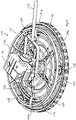
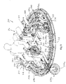
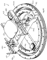
FIG. 9 is a perspective view of another concrete finishing apparatus for smoothing and leveling partially set-up concrete at a support surface in accordance with the present invention; -
FIG. 9A is a front view of the concrete finishing apparatus ofFIG. 9 ; -
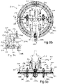
FIG. 9B is a top plan view of the concrete finishing apparatus ofFIGS. 9 and9A ; -
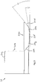
FIG. 9C is a sectional view of the tilting mechanism of the concrete finishing apparatus, taken along the line C-C inFIG. 9B ; -
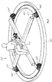
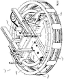
FIG. 10 is a perspective view of another concrete finishing apparatus for smoothing and leveling partially set-up concrete at a support surface in accordance with the present invention; -
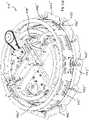
FIG. 11 is a perspective view of another concrete finishing apparatus not according to the present invention; -
FIG. 11A is a perspective view of a concrete finishing apparatus similar to the apparatus shown inFIG. 11 , with a series of trowelling blades added to the inner and outer rotatable ring working members; -
FIG. 12 is a perspective view of a walk-behind concrete finishing apparatus not according to the present invention, with a series of individual trowelling blades attached to the inner and outer ring working members; -
FIG. 12A is an enlarged perspective view of one of the adjustable trowelling blades of the apparatus ofFIG. 12 ; -
FIG. 13 is a perspective view of a large diameter, walk-behind, rotary bump cutter device for finishing concrete surfaces not according to the present invention; -
FIG. 13A is a side elevation of the rotary bump cutter device ofFIG. 13 ; -
FIG. 14 is a perspective view of the large diameter, walk-behind, rotary bump cutter device ofFIG. 13 , shown with a rotatable ring working member; and -
FIG. 15 is a perspective view of a large diameter rotary bump cutter device not according to the present invention, shown mounted to a support frame that includes an operator station for an operator to ride on the apparatus during use. - Referring now specifically to the drawings and the illustrative embodiments depicted therein, a
concrete finishing apparatus 10 for smoothing and leveling partially set-up concrete at a support surface includes amovable unit 12 having aframe portion 14, a driving device or drive motor or power source ordrive means 16 supported on the frame portion, with a set of rotatingblades 18 disposed at the base of the unit for engagement of a partially set-up concrete surface and rotatably driven by thedriving device 16, and at least one rotatablering working member 20 disposed at or mounted at the outer periphery of the movable unit (FIG. 1 ). Themovable unit 12 is movable and supported over and/or on the partially set-up concrete and may be movable in a plurality of desired directions, such as via an operator moving the unit by pushing or pulling at ahandle 22. Theblades 18 may be rotatably driven about their central axis via thedriving device 16, while the rotatablering working member 20 is rotatably driven with the blades and in the same direction as theblades 18 and about its central axis to movably engage the partially set-up, concrete surface to provide enhanced finishing of the partially set-up concrete surface, as discussed below. - The
frame portion 14 anddriving device 16 andblades 18 may be similar in construction and operation as similar components used in known power trowel devices. For example, thedriving device 16 may comprise a gas-powered engine or other suitable device or driving means that. is supported on theframe portion 14 and is operable to rotate the blades about their generally central and generally vertical axis of notation when activated. The frame portion provides a cage or cover that substantially encases or encompasses the blades to limit or substantially preclude an operator from contacting the blades during operation of the device. Themovable unit 12 may include user actuatable controls (sueh.as at thehandle 22 or the like) to allow an operator to control the rotation of theblades 18 and/or to control or adjust the rotational speed of the blades relative to the frame portion during operation of the device. - In the illustrated embodiment, the
blades 18 comprise generally flat blades or panels that are mounted to the underside of respective arms or bars 24 extending radially outward from a drive shaft of the drivingdevice 16 such that the blades are rotated in response to operation of the drivingdevice 16. The rotatablering working member 20 is disposed at and encompasses the outer ends of theblades 18 and/orarms 24 and is movable with the arms to rotate about its generally central axis of rotation. Thus, actuation of the drivingdevice 16 imparts rotation of the blades and the rotatable ring working member about their co-axial axes of rotation to work and smooth the concrete surface. - In its most basic form, the single rotatable
ring working member 20 that may be installed on a typical concrete power trowelling machine, such as a power trowel of the types that are known within the concrete construction industry. The single rotatable ring working member is of such an overall diameter, internal diameter, and cross section that the ring member is able to be attached to the outer portions of the rotating trowelling blades at the internal diameter of the ring. Thus the addition of the single rotatable ring working member fully encompass the rotating blades of the power trowelling machine and greatly increases the effective overall diameter of the machine as well as the surface contact surface area of engagement with the concrete. - The rotatable
ring working member 20 is a generally horizontal oriented ring-shaped structure or member, having a single central axis 20a of rotation whereby the axis of rotation is generally vertical and perpendicular with respect to the surface of the concrete and the like (FIGS.2, 2A, and 2B ). The rotatable ring working member includes a generally continuous profiled surface for contact and engagement with the partially set-up concrete surface. As shown inFIG. 3 , a cross-section of the rotatable ring working member, as established by an imaginary plane that is coincident with the central axis of rotation, exhibits a profile shape that defines a surface for contact and engagement with the partially set-up concrete surface. In the illustrated embodiment, the rotatablering working member 20 includes an inner wall 20b and alower working surface 20c. The profile shape of the workingsurface 20c of the rotatable ring may be generally defined and include for example, a first angle ofattack surface 20d, a second angle ofattack surface 20e, a horizontal working surface 20f, a first angle ofdeparture surface 20g, and a second angle ofdeparture surface 20h, all smoothly joined to form a generally smooth and continuous concrete working surface profile. Optionally, the structural rigidity of the rotatable ring may be enhanced, such as via use of a substantially rigid material, such as steel or the like, or such as via use of a boxed section or member or rib within and/or around the ring or such as via any other suitable stiffening means to limit or reduce flexing of the ring during operation of the machine. The design and material of the ring may be selected to provide the desired strength and rigidity without increasing the weight of the ring to a point where the ring may possibly add too much downpressure to the surface of the concrete since the ring is generally free-floating on or is generally supported on the concrete surface relative to the rest of the machine during operation. - With the generally smooth and continuous concrete working surface profile thus defined, and the profile then revolved or swept around the central axis of rotation and at a given radial distance from the central axis of rotation, a continuous concrete working surface or member in the shape of a ring is thus defined and created. The ring-shaped concrete working surface or member can generally be of any desired diameter, while the cross-sectional size of the profile of the ring may vary in proportion to the diameter such that for a given ring diameter, and various particular ring designs might include cross-sectional dimensions ranging from thin to thicker proportions as compared to the overall diameter as may be preferred. Within the general size limitations of the apparatus, the larger the overall diameter of the rotatable ring working member, the more likely it will be able to produce the desired high level of flatness and smoothness quality of the concrete surface.
- In the illustrated embodiment, the rotatable
ring working member 20 comprises a floating ring that is loosely disposed at the outer ends of the blades, such as at outer ends of a plurality of ring drive bars 26 extending radially outward from the outer ends of theblades 18 and/orarms 24. As can be seen with reference toFIG.1 , the inner wall 20b generally abuts or is located at or near the outer ends of the drive bars 26 and includes a plurality of engagingtabs 20i (FIG. 2 ) extending radially inward from the inner wall 20b, whereby the drive bars 26 engage thetabs 20i to impart rotational movement of the rotatablering working member 20 when the driving device is activated to rotate thearms 24 andblades 18. The inner wall 20b allows for vertical movement of the rotatablering working member 20 relative to the drive bars 26 so that the rotatablering working member 20 is supported on the concrete surface and generally floats on the concrete surface. The rotatablering working member 20 includes an upper lip orwall 20j to limit downward movement of the rotatablering working member 20 relative to the drive bars 26. - Typical concrete power trowel machines include a plurality of toweling blades that are rotatably driven at various speeds by a power source such as an internal combustion engine. The machine is controlled by an operator who maintains control of the unit through a set of handlebars as the operator stands or walks along with the machine. With this configuration, these types of machines are generally known in the industry as walk behind concrete power trowels. The overall diameter of the walk behind power trowel rotating blades may typically range from 24 to 54 inches (60 to 137 cm) and larger. The multiple rotating blades for engagement with the partially-cured concrete surface are generally and readily adjustable with respect to their angle of attack relative to the concrete surface as desired by the operator. The angle of attack of the blades is thus adjusted together in unison depending upon the desired results and the specific concrete surface finishing operation underway. Generally, blades that are held in a flat position or providing a very minimal angle of attack are used when concrete surface floating operations are underway. Concrete floating operations are used to accomplish several primary tasks including, for example: (1) to embed larger aggregate just below the surface, (2) to reduce or eliminate imperfections, bumps, and voids in the concrete surface, (3) to help compact the concrete and consolidate the mortar at the surface in anticipation of further finishing operations (such as finish trowelling), and/or (4) to open the surface of the concrete which may have started to crust over before the remaining finishing operations have begun. When the blades are adjusted to progressively more aggressive angles of attack relative to the concrete surface, such angle settings are consistent with a series of typical final trowelling operations.
- Optionally, the concrete power trowel may be fitted with different sets of blades as desired for a more a specific operation. For example, wider blades that are about 10 inches (about 25 cm) wide are mainly used for floating operations, while narrower finishing blades that are about 6 inches (about 15 cm) wide are used for trowelling and finishing operations after floating operations are complete. Combination blades that are about 8 inches (about 20 cm) wide can provide both floating and finish trowelling capabilities in one blade. To provide both floating and finishing characteristics the combination blades have a leading edge that is slightly pitched upward allowing concrete to flow below the flattened blade for floating operations, while the trailing edge is straight and square to provide finish trowelling capabilities when the blades are aggressively angled.
- As a further option, concrete power trowel blades can be replaced with pan floats, float disks, or simply pans. These are circular metal disks having an overall diameter matching the overall diameter of the rotating blades. The outer edge of the pan is turned upward along its periphery to allow concrete to pass under it. The underside and contact face of the pan can be either flat or slightly convex relative to the concrete surface. Pans, like the wider float blades, are used specifically for concrete floating operations. The advantages of using pans are that they can generally increase the productivity of the machine during floating operations. An increase in contact surface area of a pan reduces the contact pressure of the machine on the surface of the concrete as compared to blades, and because they are generally flatter than blades, the accuracy and flatness of the concrete surface can be generally improved.
- As stated above, the addition of the single rotatable ring working member added to a typical concrete power trowelling machine greatly increases the effective overall diameter of the machine as well as the contact surface area of engagement with the concrete. In the illustrated embodiment, the single rotatable working ring is rotatably driven by the blade arms. Thus, during floating operations, the blades and the rotatable ring working member rotate in unison about their co-axial axes of rotation. The rotatable working ring however is able to float freely in a vertical direction relative to the rotating blade arms and the blades while in contact with the surface of the concrete. The further advantage of this is that it the rotatable working ring is able to freely ride up and over any bumps or high areas that may be present in the surface of the concrete. As the machine progresses along in any direction over the concrete surface, the contact surface of the ring tends to cut down and reduce any bumps and high areas. In similar fashion, the frictional contact between the concrete and the rotatable working ring tends to transport and carry along any of the extra material (concrete paste, sand, and small aggregate) from the bumps and high areas to then fill any holes or low areas that may be present in the surface. This inherent leveling action along with the increased overall effective diameter of the machine, provides a significant increase in the productivity of the machine, and an overall increase in the flatness and levelness quality capabilities provided by a typical walk behind concrete power trowel. Thus, the addition of the floating rotatable ring working member to a walk behind concrete power trowel provides increased productivity and increased concrete surface quality without the added cost of an additional process step, finishing operation, or any significant required increase in skill level by the operator.
- One potential disadvantage of the above is, that the addition of the rotatable working ring tends to increase the torque reaction of the rotating blades and working ring at-the operator's handlebars. The operator will be required to hold onto the machine's handlebars more tightly due to the tendency of the handlebar to rotate when the driving device is operated. A longer handlebar design can help offset the increased torque reaction experienced by the operator; however, providing a pair of oppositely rotating rings may substantially reduce the torque reaction at the handlebars, as discussed below.
- Referring now to
FIG. 4 , aconcrete finishing apparatus 110 for smoothing and leveling partially set-up concrete at a support surface includes amovable unit 112 having aframe portion 114, a driving device or drive motor or power source or drive means 116 supported on the frame portion, with a set ofrotating blades 118 disposed at the base of the unit for engagement of a partially set-up concrete surface and rotatably driven by the drivingdevice 116, and at least two rotatablering working members movable unit 112 is movable and supported over and/or on the partially set-up concrete and may be movable in a plurality of desired directions, such as via an operator moving the unit by pushing or pulling at ahandle 122. Theblades 118 may be rotatably driven about their central axis via thedriving device 116, while the rotatablering working members - Rather than only using a single rotatable ring working member rotating in a single direction and in unison with a set of rotating blades,
concrete finishing apparatus 110 includes the first or inner rotatablering working member 120 that is able to be driven in either direction relative to the rotation of the blades (such as in the same direction as the blades), and the second or outer rotatablering working member 121 of a larger diameter than the first and concentrically and additionally disposed to the outside perimeter of the firstrotatable ring member 120. The second ring is operable to be driven in a direction opposite the direction of rotation of the first ring, as discussed below.Concrete finishing apparatus 110 may be otherwise similar toconcrete finishing apparatus 10, discussed above, such that a detailed discussion of the devices need not be repeated herein. - In the illustrated embodiment,
frame portion 114 includes anupper frame member 114a that extends over the rotatablering working members FIG. 4 or more or less depending on the particular application) that are rotatably attached to theupper frame member 114a. Theplanetary gears 128 engage an outer toothed or cogged surface 120k of inner rotatablering working member 120 and an inner toothed or cogged surface 121k of outer rotatablering working member 121. In the illustrated embodiment,inner ring member 120 is connected to or engaged by the drive bars 126 ofblades 118 and arms 124 and is rotatably driven via rotation of theblades 118 by the drivingdevice 116, such as in a similar manner as described above (and the inner ring member may be vertically movable relative to the blades and drive bars such as in a similar manner as described above). The outer rotatablering working member 121 is driven by the engagement of the gear wheels orplanetary gears 128 rotatably mounted to the stationary ring member orupper frame member 114a of the support structure orframe portion 114 of theapparatus 110. - The cogs or gear teeth cut into the surfaces 120k, 121k of the respective inner and outer rotatable
ring working members gear wheels 128. In this way, as theinner ring 120 andblades 118 are rotatably driven, the outer ring is rotatably driven in the opposite direction and at nearly the same speed (a slight speed difference may result as the inner and outer rotating ring members each have different diameters and circumferences and thus a different number of cogs or gear teeth). As with the single ring device orapparatus 10, discussed above, bothrings apparatus 110 may be free to move or otherwise float in a generally vertical direction with respect to the support structure of the machine, the rotating blades, and the surface of the concrete. Such vertical movement may be facilitated by the teeth or cogs of surfaces 120k, 121k sliding generally vertically along the gear pins of the gear wheels orplanetary gears 128. Thus, by providing opposite rotating ring members that engage the concrete surface, the average resultant torque reaction at the handlebars of a walk behind concrete power trowelling machine can be greatly reduced and essentially eliminated. The second ring offers the further advantages of further increasing the working surface contact area of the machine, and therefore further improves both the productivity machine and the resulting quality of the concrete surface. - Optionally, it is envisioned that the concrete finishing apparatus or machine may be responsive to a laser leveling or laser control system that is operable to control or adjust the elevation of the rotatable ring or rings relative to the frame portion and blades during operation of the apparatus. For example, the apparatus may include two or more (such as, for example, three) laser receivers at the rotatable ring (such as mounted to masts or support rods extending upward from the rotatable ring). The laser receivers may detect a laser plane generated by a laser plane generating device at the support surface, and may be used with an elevation control system to control the elevation of the rotatable ring, such as by adjusting the down pressure or level of the rotatable ring relative to the frame portion, such as via three independently controlled linear actuators, such as a linear actuator at or near each of the planetary gears that support the frame portion and blades relative to the outer ring. This would allow the ring to be held at the desired grade elevation relative to the power trowel's spinning blades.
- With such a laser control system, the concrete finishing apparatus may provide enhanced surface quality by maintaining the rings at an appropriate level or grade and adjusting a down pressure of the rings relative to the blades to maintain the rings at the desired or appropriate or selected level or grade. The relative sizing of the blades and rings, along with the design or form of the contact surfaces, and proportional weights of the spinning blades and rings may be selected to provide the desired results. Likewise, the control system may be adjusted to provide the desired results depending on the particular application of the apparatus on different concrete types and conditions.
- Optionally, it is envisioned that in some applications, such as where the weight of the rings is increased, the apparatus may include a means for providing an upwardly directed force to counteract any excess ring weight or otherwise effectively adjust the down pressure of the rings. For example, adjustable linear coil springs or air springs or the like in combination with the linear actuators that control the ring elevation may provide advantages for controlling the ring down pressure.
- Thus, and particularly for any given smaller areas of concrete relative the overall diameter of the outer ring, a laser-guided elevation control may provide enhanced performance of the apparatus and may provide minor corrections to the concrete elevation. The apparatus thus may provide improved or enhanced accuracy of a finished concrete floor or surface.
- During operation, the apparatus is substantially supported by the spinning blades while the spinning ring simply floats on the concrete surface in an effort to generally averageout or even-out the existing surface imperfections, and the outer ring is the last thing in contact with the concrete surface as the apparatus or machine advances. In order to provide enhanced control of the elevation of the outer ring, the laser control system may control the elevation of at least the outer ring by small amounts relative to the central blades. Optionally, it is envisioned that the apparatus may control the relative pitch or angle of attack of the ring relative to the spinning blades with respect to the speed and direction of travel of the machine over the surface. The apparatus may include any suitable or appropriate electronic sensors, computerized controls, and software and/or circuitry to accomplish such tasks for the operator, and optionally the apparatus may automatically accomplish such tasks or may accomplish such tasks responsive to a user or operator input.
- Typically, if the concrete floor or surface is placed and leveled using a lasercontrolled laser screeding device, such as a Somero LASER SCREED™, any necessary or desired elevation corrections to the concrete surface should be relatively small, since the overall levelness of the floor or surface should already be accurate. Any necessary elevation corrections would thus likely be relatively small and limited to minor defects in proportion to the overall diameter of the outer spinning ring. A concrete finishing apparatus as described above that includes laser receivers and an elevation control system may offer advantages in an enhanced capability of the machine to effectively improve the accuracy of the 'finished concrete floor or surface.
- Optionally, the concrete finishing apparatus may comprise a ride-on construction that allows an operator to ride the apparatus during operation of the concrete finishing apparatus. For example, and with reference to
FIGS. 5 ,6 and 6A , aconcrete finishing apparatus 210 for smoothing and leveling partially set-up concrete at a support surface includes a movable unit 212 having aframe portion 214, a driving device or drive motor or power source or drive means 216 supported on the frame portion, with two sets ofrotating blades device 216, and at least two rotatablering working members blades ring working members - The power trowelling machine or unit, with two sets of rotating blades at the base of the unit, allows the operator to be positioned on the machine itself (such as at an operator station or seat 213) while in operation as opposed to the walk behind version, discussed above. Such types of power trowelling machines are known in the concrete construction industry as "ride-on" power trowels. These machines are-typically subject to the same selections of rotating blade options as the walk behind machines, such as, for example, floating, trowelling, and combination blades as well as the option of pan floats, float disks, or simply pans. The
operator station 213 may include one or more user inputs orcontrols 213a, such as levers or switches or other user actuatable controls or inputs, for the operator to actuate or adjust to operate and control the machine, such as to control the motors of the blades and/or rings. Optionally, theconcrete working apparatus 210 may be driven or steered via tilting or raising/lowering the ring members relative to one another, such as discussed below. - Similar to
apparatus 110, discussed above,apparatus 210 includes a plurality of gear wheels orplanetary gears 228 rotatably mounted to an upper frame member 214a offrame portion 214 that extends over the rotatablering working members planetary gears 228 at the respective corners of theframe portion 214. Eachplanetary gear 228 engages the outer toothed or coggedsurface 220k of inner rotatablering working member 220 and an inner toothed or coggedsurface 221k of outer rotatablering working member 221. The inner and outer workingmembers blades members device 217 that is operable to rotatably drive one (or two or more) of theplanetary gears 228, whereby rotation of the drivenplanetary gear 228 imparts a rotation of one of the workingmembers members - For example, and in similar fashion to
apparatus 110, discussed above, cogs or gear teeth are cut or formed or established at or on or into the surfaces of the respective inner and outer rotatable ring working members and engage a series of drive pins or teeth of each of the gear wheels. In this way, as the driven gear wheel is rotatably driven, the inner ring is rotatably driven in one direction and the outer ring is rotatably driven in the opposite direction and at nearly the same speed (a slight speed difference may result as the inner and outer rotating ring members have different diameters and circumferences and thus have a different number of cogs or gear teeth along their respective opposed surfaces). Optionally, and desirably, the inner andouter ring members apparatus 210 may be free to move or otherwise float in a generally vertical direction with respect to the support structure of the machine, the rotating blades, and the surface of the concrete. Such vertical movement may be facilitated by the teeth or cogs ofsurfaces planetary gears 228. - Because the inner ring member is not driven via engagement with the blades, the inner and outer rotatable ring members may be driven at various speeds that are completely independent of the rotational speed of the two blade assemblies. This is made possible by the addition of the separate drive motor (such as a hydraulic motor or other suitable driving means) for the sole purpose of independently driving the rotatable ring working members. Such a construction also provides the further advantages of independent drives and operatorselective variable speed control of the now separate blade assemblies and the rotating ring concrete finishing members.
- Optionally, and with reference to
FIG. 7 , the concrete finishing apparatus 210' may include a cover 215' (which may cover the blades and frame of the apparatus and upon which the operator station 213' may be positioned) with the two sets of rotating blades for engagement of a partially set-up concrete surface under the cover, and at least two rotatable ring working members 220', 221' loosely or movably or rotatably mounted at the outer periphery of the movable unit, with the two rotatable ring working members being driven in opposite directions via one or more driving devices 217', such as hydraulic motors or the like, rotatably driving one or more rotational drive members 228', such as planetary gears or rubber drive tires or the like, that are mounted to the frame portion 214' and that engage the opposed inside vertical faces or walls or surfaces of the respective rings. - In the illustrated embodiment, the inner rotatable ring working member 220' includes an inner wall or surface 220b' and a lower, generally planar working
surface 220c', while outer rotatable ring working member 221' includes an outer wall or surface 221b' and a lower, generally planar workingsurface 220c'. The rotational drive member or drive wheel or tire 228' frictionally engages the opposed surfaces 220b', 221b', and thus drives one ring member in one direction and the other ring member in the opposite direction in response to rotational driving of the drive wheel or tire (or wheels or tires) via the respective drive motor (or motors). Concrete finishing apparatus 210' may be otherwise similar to the concrete finishing devices discussed above, such that a detailed discussion of the devices need not be repeated herein. - Optionally, and with reference to
FIG. 8 , aconcrete finishing apparatus 210" may not include rotating blades for engagement of a partially set-up concrete surface under the cover, but includes aframe portion 214" and at least two rotatablering working members 220", 221" loosely mounted at the outer periphery of the movable unit for engagement of a partially set-up concrete surface, with the two rotatable ring working members being driven in opposite directions via one ormore driving devices 217", such as hydraulic motors or the like, rotatably driving one or morerotational drive members 228", such as planetary gears or rubber drive tires or the like, that engage the opposed inside vertical faces or walls or surfaces of the respective rings. The stand alone unit may be steered by the operator at theoperator station 213", such as by tilting or raising/lowering the rings with respect to one another, and while the two rotatable ring working members are driven in opposite directions via hydraulic motors and rubber drive tires at the inside vertical faces of the respective rings, such as discussed below, The tilting of the rings may be accomplished via tilting thering rotation wheels 228", which may urge one of the rings downward and allow the other ring to raise upward so that the downward urged ring engages the concrete surface and causes the apparatus to move or rotate (because the other ring is in reduced contact or is not in contact with the concrete surface and thus does not counter the rotational forces of the downward urged ring) one way or the other. Optionally, and as shown inFIG. 8 , theapparatus 210" may include a pair ofring rotation wheels 228" at respective opposite ends of a frame cross member and a pair ofsupport wheels 229" at respective opposite ends of another frame cross member, such that thering rotation wheels 228" are about 180 degrees apart and thesupport wheels 229" are likewise about 180 degrees apart. - Optionally, and with respect to
FIGS. 9 and9A-C , aconcrete finishing apparatus 310 may or may not include rotating blades (not shown inFIGS. 9 and9A-C ) for engagement of a partially set-up concrete surface under the cover, but includes a frame portion 314 and at least two rotatablering working members more driving devices 317, such as hydraulic motors or the like, rotatably driving one or morerotational drive members 328, such as planetary gears or rubber drive tires or the like, that engage the opposed inside vertical faces or walls or surfaces of the respective rings. Theapparatus 310 may include a power source or engine or power system 316 (such as an internal combustion engine and a hydraulic pump and reservoir for operating thehydraulic motors 317 and/orhydraulic motors 338d and/or the like). The stand alone unit may be steered by an operator at theoperator station 313 by tilting or raising/lowering the rings with respect to one another, such as via atilting mechanism 330, and while the two rotatable ring working members are driven in opposite directions via hydraulic motors and rubber drive tires at the inside vertical faces of the respective rings, such as in a similar manner as discussed above. Tilting of the ring rotation wheels may raise one ring upward while the other ring remains in contact with the concrete surface, which may cause the apparatus to move or rotate one way or the other (depending on the direction of rotation of the ring that is in contact with the concrete surface), such as discussed above. - In the illustrated embodiment, the frame portion 314 comprises a pair of elongated cross members with gear wheels or
planetary gears 328 rotatably mounted at the outer ends of the frame cross members. Theplanetary gears 328 include teeth or pins that engage teeth or pins of the inner andouter ring members hydraulic motor 317 or other suitable driving device or drive means) rotates theinner ring member 320 in one direction and theouter ring member 321 in the opposite direction, such as in a similar manner as discussed above. As also described above, thering members planetary gears 328 so as to float relative to one another during operation of the apparatus and so as to allow for movement and/or tilting of the ring members relative to one another in response to thetilting mechanism 330. - In the illustrated embodiment,
tilting mechanism 330 comprises a pair of wheels orrollers 332 mounted at each end of the frame cross member 314a, and that are pivotable about a generally horizontal pivot axis to adjust the tilt of the outer ring member relative to the inner ring member. Thewheels 332 are rotatable about a generally horizontal axis of rotation and rollingly engage anupper surface wheels 332 are rotatably mounted (such as via acommon axle 332a) to a mountingplate 334, which is connected to or joined with or includes a linkage orarm 336a extending generally upwardly therefrom. Thewheels 332 thus may be pivoted in response to pivotal movement of the linkage orarm 336a, such as in response to generally translational movement of another linkage orarm 336b, which has one end pivotally connected to an upper end of linkage orarm 336a and its opposite end pivotally connected to a linkage orarm 336c, which in turn is pivotally mounted to the frame cross member 314a. Alinear actuator 336d (or other suitable actuating device) is mounted to the frame cross member and to an upper end of the linkage orarm 336c, whilearm 336b is connected to a mid-region ofarm 336c. - Thus, actuation (extension or retraction) of the linear actuator (which may comprise a hydraulic cylinder or electric actuator or the like) imparts a pivotal movement of
arm 336c relative to the frame cross member, which imparts a generally translational movement ofarm 336b in a radially outward direction (if the actuator is extended) or radially inward direction (if the actuator is retracted), which in turn imparts a pivotal movement ofarm 336a andplate 334 and thusaxle 332a andwheels 332. Such pivotal movement ofaxle 332a andwheels 332 thus adjust or moves or urges one of thering members - Thus, the apparatus may be driven or controlled by an operator seated at a
control station 313 or operator station of the apparatus. Optionally, user inputs orlevers 313a may be provided at the operator station to allow the driver or operator to control the actuators and the rotational speed of the drive motors and the like during operation of the machine. For example, the operator may move a lever or input to actuate theactuators 336d (such as to actuate the actuators together), such as to extend the actuators to lower the outer ring and allow the inner ring to raise upwardly relative to the outer ring, in order to turn in one direction, and may move the lever or input in a different direction to actuate theactuators 336d, such as to retract the actuators to lower the inner ring and allow the outer ring to raise upwardly relative to the inner ring, in order to turn the apparatus in the other direction. - Optionally, the
apparatus 310 may include a set of drop-down wheel assemblies 338, which include tires orwheels 338a, which may be raised to a level above the working surfaces of the ring members during operation of the concrete finishing apparatus, and which may be lowered to a level below the working surface of the ring members so as to raise the ring members above the support surface to allow for easier movement of the machine over general surfaces during transport from one location to another. Thewheel assemblies 338 may be adjustable via anactuator 338b (such as a hydraulic cylinder or the like) that pivots a mountingarm 338c relative to the frame cross member 314a to raise and lower thewheels 338a. Optionally, one or more of thewheels 338a may be rotatably driven, such as via ahydraulic motor 338d or other suitable driving device or drive means. Optionally, and such as shown at the front of the apparatus, awheel assembly 339 may include awheel 339a and may be removably mounted to a mounting frame or bracket at the front of the apparatus. Thefront wheel 339a may be freely pivotable about a generally vertical axis and may be pivotable or steerable by the operator of the apparatus, such as via pivotal movement of a steering arm orcontrol lever 339b or the like. - With reference to
FIG. 10 , aconcrete finishing apparatus 410 includes a frame portion 414 and at least two rotatablering working members driving device 417 rotatably driving one or more rotational drive members, such as a planetary gear or gears or rubber drive tires or the like being rotatably driven via a chain-drivengear 429 by a rotary drive device or motor or engine (not shown inFIG. 10 ). The planetary gears or tires engage the opposed inside vertical faces or walls or surfaces of the respective rings, as discussed above, so as to drive the rings in opposite directions. The stand alone unit may be steered by tilting or raising/lowering the rings with respect to one another, such as via atilting mechanism 430, and while the two rotatable ring working members are driven in opposite directions via hydraulic motors and rubber drive tires at the inside vertical faces of the respective rings, such as in a similar manner as discussed above. - In the illustrated embodiment,
tilting mechanism 430 comprises a pair of wheels or rollers or the like mounted at each end of theframe cross member 414a, and that are pivotable about a generally horizontal pivot axis to adjust the tilt of the outer ring member relative to the inner ring member. The wheels are rotatable about a generally horizontal axis of rotation and rollingly engage anupper surface linkage mechanism 436, which is operable to pivot the axle and wheels in response to the operator pivoting or moving or actuating a user input orlever 437, such as in a similar manner as discussed above. - Optionally, and with reference to
FIG. 11 , a concrete finishing apparatus 410' may include upper members or lift rings 440', 441' disposed above the tilt wheels 432' and above and around the circumference of the respective ring members 420', 421'. Thus, when the tilt wheels 432' are tilted so that one of the wheels urges one of the ring members 420', 421' downward, the other tilt wheel urges against the lower surface of the respective lift ring 440', 441' to raise or lift the other ring member 420', 421' upward, in order to enhance the relative movement or tilting or raising/lowering of the ring members to enhance control of the apparatus on the concrete surface. For example, an operator may control the apparatus so as to urge the inner ring downward and to urge the outer ring upward so as to substantially reduce the contact of the outer ring at the concrete surface (and may raise the outer ring above the concrete surface) to turn in one direction and may control the apparatus so as to urge the outer ring downward and to urge the inner ring upward so as to substantially reduce the contact of the inner ring at the concrete surface (and may raise the inner ring above the concrete surface) to turn in the opposite direction to enhance the steering of the apparatus as it moves over the concrete surface. - As shown in
FIG. 11 , the apparatus is shown without a power source or engine and with the seat removed from the apparatus, in order to show a hydraulic drive motor 417' that may be driven by pressurized fluid, such as through a pair of hydraulic hoses connected to the motor and to a remotely stationed hydraulic power source. Thus, the apparatus may receive its power or pressurized fluid from a remote device, such that the apparatus need not include an engine and pump and reservoir and the like, such that the apparatus may have substantially reduced weight as compared to the other devices and machines discussed above. Concrete finishing apparatus 410' may be otherwise similar toconcrete finishing apparatus 410, discussed above, such that a detailed discussion of the apparatus need not be repeated herein. - Optionally, and with reference to
FIG. 11A , aconcrete finishing apparatus 410" may include a plurality of trowelling blades or pans 442", 443" attached to the lower surfaces of therespective ring members 420", 421", The trowelling pans provide a larger surface area that engages and works the concrete surface to further finish the concrete surface. The trowelling pans may be attached to the ring members after the apparatus has processed or worked the partially set up concrete surface. - In the illustrated embodiment, the trowelling pans 442", 443 " are attached to the
respective ring members 420", 421" via a hitch pin attachment assembly or configuration 444". For example, a plurality of pin receivers orcollars 446" may be attached to the ring members and spaced apart around the circumference of the ring members (such as around the outer circumference of the outer ring member and around the inner circumference of the inner ring member). Each trowelling pan may include a mounting pin orsupport pin 448" extending upwardly therefrom, such as upwardly from a rearward region or trailing end region of the trowelling pan, whereby the mounting pin may be received in therespective collars 446" to position the trailing region of the trowelling pan, while the leading region of the trowelling pan may overlap or overlay the adjacent trowelling pan in the direction of rotation of the ring member. Ahitch pin 450" (such as a cotter pin or the like) may be inserted through a hole or passageway in the collar and through a generally aligned hole or passageway through the mounting pin to secure the respective trowelling pan to the ring member. Optionally, and desirably, the mounting pins may have a plurality of holes or passageways spaced therealong, so that the level of the rear or trailing region of the trowelling pans may be adjusted via adjustment of the mounting pin along the collar and insertion of the hitch pin into a desired or appropriate one of the holes or passageways in the mounting pin. - Thus, each support pin includes multiple through holes for engagement of the hitch pin and to allow for the desired adjustment of the angle-of-attack between the blades or pans and the surface of the concrete, such as might be used for final concrete finishing and trowelling operations. For example, the pins may be lowered relative to the collars to increase the angle of attack of the blades or pans, or the pins may be raised relative to the collars to decrease the angle of attack of the blades or pans, depending on the particular application and operation of the concrete finishing apparatus.
Concrete finishing apparatus 410" may be otherwise similar to concrete finishing apparatus' 410, 410', discussed above, such that a detailed discussion of the apparatus need not be repeated herein. - Optionally, and with reference to
FIGS. 12 and 12A , aconcrete finishing apparatus 510 may comprise a walk-behind type of machine or device and may include ahandle 522 for an operator to move the apparatus over the concrete surface.Concrete finishing apparatus 510 may include a plurality of trowelling blades or pans 542, 543 attached to the lower surfaces of therespective ring members - In the illustrated embodiment, the trowelling
blades 542 extend radially inward from theinner ring member 520 andtrowelling blades 543 extend radially outward from theouter ring member 521. The trowelling blades may be detachably attached to the ring members or may be fixedly secured to the ring members, such as via welding or the like. Each trowelling blade may include anangle adjustment device 544 that is adjustable to adjust the angle of attack of the respective trowelling blade. In the illustrated embodiment, theadjustment device 544 comprises abracket 546 that is fixedly mounted to the ring member and apivot pin 548 that is connected to or joined to the trowelling blade. Anangle adjustment knob 550 includes a threaded portion that threadedly extends through a threaded passageway inbracket 546 and engages an arm 548a extending frompivot pin 548. Thus, when theknob 550 is rotated, the engagement of the threaded portion moves relative to the bracket to impart a movement of the arm 548a, which imparts a pivotal movement ofpivot pin 548 and thus pivotal adjustment of the trowelling blade. Other means for adjusting an angle of attack of the trowelling blades may be implemented. - As can be seen in
FIG. 12 , thehandle 522 may be connected to the linkage or tilt mechanism 530, whereby movement of the handle relative to the frame portion 514 may actuate or adjust the linkages to cause tilting or raising/lowering of one of the ring members relative to the other ring member, such as in a similar manner as discussed above. It is envisioned that the handle may be oriented as shown inFIG. 12 , such that movement of the handle to push or pull the unit may affect the tilting/raising/lowering of the ring members, or the handle may be oriented or adjusted to be generally normal to the position shown inFIG. 12 , such that an operator may rotate the handle to affect the tilting or raising/lowering of the ring members via the tilt mechanism.Concrete finishing apparatus 510 may be otherwise similar to concrete finishing devices or machines discussed above, such that a detailed discussion of the apparatus need not be repeated herein. - Optionally, and with reference to
FIGS. 13 and 13A , a large diameter, walk-behind, rotarybump cutter device 610 may be provided for finishing concrete surfaces.Bump cutter device 610 includes a plurality of arms or members orblades 618 extending radially outward from a central axis or axle oroutput shaft 616a of adrive motor 616. Thearms 618 may comprise elongated arms or blades with a generally planar lower surface for engaging the concrete surface. The drive motor is operable to rotate the elongated arms orblades 618 to rotate the arms or blades and to work or process the concrete surface, while an operator moves and/or controls the device via ahandle 622. - Optionally, and with reference to
FIG. 14 , the rotary bump cutter device 610' may include a rotatable ring working member 620' that is rotatable with the anus orblades 618, such as in a similar manner as discussed above with respect toapparatus 10. Optionally, the rotatable ring working member 620' may float or may be vertically movable relative to the arms or blades to generally float at the concrete surface, such as also discussed above with respect toapparatus 10. - Optionally, and with reference to
FIG. 15 , a large diameter rotarybump cutter device 610" includes a plurality of arms or members orblades 618" extending radially outward from a central axis or axle oroutput shaft 616a" of adrive motor 616", with the motor and output shaft being mounted to asupport frame 614" that includes an operator station for an operator to ride on the apparatus during use. Thesupport frame 614" may comprise a wheeled frame, and may include threedrive wheels 638" (with one or more of the drive wheels optionally being driven, such as via a hydraulic motor or the like), with telescoping supports 639" for the drive wheels so as to allow for adjustment and control of the height of the rotary bump cutter blades. The drive motor may be a hydraulic motor or other suitable drive device, and the support frame may support the power source (such as an engine and pump and reservoir for a hydraulic motor or the like), or the power source may be remotely located with hydraulic lines connecting to the drive motor. - Therefore, the present invention provides a concrete finishing apparatus or device or machine and method for smoothing and flattening partially set-up concrete to a close-tolerance surface. The concrete finishing apparatus of the present invention provides rotatable ring portions for engaging a partially cured concrete surface to process or work the concrete surface while the apparatus is moved and supported on or over the partially set-up concrete surface. The rotatable ring finishing member is positioned at the concrete surface and rotatable to engage and finish the surface of the partially set-up concrete to a higher quality, closer-tolerance flat and level concrete floor surface. The apparatus includes a pair of rotatable ring finishing members that are rotatable in opposite directions to one another to enhance the floating and finishing processes and to transport any cement paste, sand, small aggregate, or concrete mix residue forward with the rotatable ring finishing members working surfaces to cut high areas and fill in any low areas as the concrete finishing apparatus moves over the partially set-up concrete. The ring members are disposed around a periphery of the device. The concrete smoothing and leveling apparatus of the present invention is capable of finishing a concrete floor or surface to a higher degree of quality than current methods and practices of concrete construction.
Claims (9)
- A concrete finishing apparatus (210", 310, 410) for smoothing and leveling partially set-up concrete at a support surface, said concrete finishing apparatus comprising:a frame portion (214", 314, 414);an inner ring working member (220", 320, 420), disposed at an outer periphery of said frame portion and rotatable about a first axis of rotation, and wherein said first axis of rotation is generally vertical when said inner ring working member is supported at a generally horizontal support surface; an outer ring working member (221", 321, 421) disposed at an outer periphery of said frame portion and generally about a periphery of said inner ring working member, wherein said outer ring working member is rotatable about a second axis of rotation that is generally vertical when said outer ring working member is supported at a generally horizontal support surface;at least one driving device (217", 317, 417) operable to rotatably drive said inner ring working member and said outer ring working member;at least one rotational drive member (228", 328, 428) driven by said driving device (217", 317, 417);wherein said inner ring working member and outer ring working member engage the partially set-up concrete surface at the support surface to process the partially set-up concrete surface;characterised in that said inner ring working member and said outer ring working member both include a vertical wall and wherein said vertical walls are opposed to each other, wherein said driving device rotatably drives one or more of said rotational drive members (228",328,428) to engage said opposed vertical walls of said inner and outer ring working members and rotate said inner and said outer ring working members in opposite directions.
- The concrete finishing apparatus of claim 1, wherein said apparatus is steerable by selectively urging one of said inner ring working member and said outer ring working member downward or upward relative to the other of said inner ring working member and said outer ring working member.
- The concrete finishing apparatus of claim 2, wherein said inner ring working member or said outer ring working member is selectively urged downward or upward relative to the other of said inner ring working member or said outer ring working member via tilting of the rotational drive members (228", 328, 428).
- The concrete finishing apparatus of any proceeding claim, wherein said rotational drive members (228", 328, 428) are a planetary gear, gear wheels or rubber drive tires.
- The concrete finishing apparatus of any proceeding claim, wherein said driving devices (217", 317, 417) include hydraulic motors.
- The concrete finishing apparatus of any proceeding claim, wherein a power source or engine or power system (316) such as an internal combustion engine and a hydraulic pump and reservoir are included for operating said driving devices (217", 317, 417).
- The concrete finishing apparatus of any preceding claim, wherein said concrete finishing apparatus is configured to support an operator so as to provide a ride-on apparatus.
- The concrete finishing apparatus of any preceding claim, wherein said first and second axes of rotation are generally coaxial.
- A method for smoothing and leveling partially set-up concrete at a support surface, said method comprising:providing a concrete finishing apparatus (210", 310, 410) according to any of claims 1-8;rotating the rotational drive member (228", 328, 428) which engages the vertical wall of said inner ring working member about a first axis of rotation to process the partially set-up concrete surface; androtating the rotational drive member (228", 328, 428) which engages the vertical wall of said outer ring working member about a second axis of rotation to process the partially set-up concrete surface, wherein said second axis of rotation is generally vertical when said outer ring working member is supported at a generally horizontal support surface.
Applications Claiming Priority (2)
| Application Number | Priority Date | Filing Date | Title |
|---|---|---|---|
| US3179608P | 2008-02-27 | 2008-02-27 | |
| PCT/US2009/035397 WO2009154814A2 (en) | 2008-02-27 | 2009-02-27 | Concrete finishing apparatus |
Publications (4)
| Publication Number | Publication Date |
|---|---|
| EP2271804A2 EP2271804A2 (en) | 2011-01-12 |
| EP2271804A4 EP2271804A4 (en) | 2017-04-05 |
| EP2271804B1 true EP2271804B1 (en) | 2022-04-13 |
| EP2271804B8 EP2271804B8 (en) | 2022-05-18 |
Family
ID=40998471
Family Applications (1)
| Application Number | Title | Priority Date | Filing Date |
|---|---|---|---|
| EP09767127.5A Active EP2271804B8 (en) | 2008-02-27 | 2009-02-27 | Concrete finishing apparatus |
Country Status (9)
| Country | Link |
|---|---|
| US (2) | US7891906B2 (en) |
| EP (1) | EP2271804B8 (en) |
| CN (1) | CN102016179A (en) |
| AU (1) | AU2009260765A1 (en) |
| BR (1) | BRPI0908481A2 (en) |
| CA (1) | CA2717005C (en) |
| MX (1) | MX2010009506A (en) |
| RU (1) | RU2010139448A (en) |
| WO (1) | WO2009154814A2 (en) |
Families Citing this family (36)
| Publication number | Priority date | Publication date | Assignee | Title |
|---|---|---|---|---|
| EP1610874A4 (en) * | 2003-03-25 | 2008-04-23 | Somero Entpr Inc | Apparatus and method for improving the control of a concrete screed head assembly |
| CA2717005C (en) * | 2008-02-27 | 2015-08-04 | Somero Enterprises, Inc. | Concrete finishing apparatus |
| US7851345B2 (en) * | 2008-03-19 | 2010-12-14 | Stats Chippac, Ltd. | Semiconductor device and method of forming oxide layer on signal traces for electrical isolation in fine pitch bonding |
| ES2395242B1 (en) * | 2010-09-23 | 2013-12-23 | Conrado Pont Feixes | MACHINE TO FRATE SOILS. |
| US8439600B2 (en) | 2011-01-17 | 2013-05-14 | Scott Brening | Portable vibratory concrete float |
| ITVI20110084A1 (en) * | 2011-04-05 | 2012-10-06 | Lomar S R L | MACHINE AND METHOD FOR THE CONSTRUCTION OF FLOOR SUBSTRATES |
| CA2746681A1 (en) | 2011-07-11 | 2013-01-11 | Andrzej R. Biernacki | Screed system and method |
| WO2015089164A2 (en) * | 2013-12-10 | 2015-06-18 | Andale Paving, Inc. | Concrete slab forming method |
| US9808959B2 (en) | 2014-08-22 | 2017-11-07 | Peter Molitor | Concrete slab forming method |
| AU2015253384B2 (en) | 2014-04-28 | 2019-01-24 | Somero Enterprises, Inc. | Concrete screeding system with floor quality feedback/control |
| CN105369718B (en) * | 2015-04-22 | 2017-05-10 | 涂霞荔 | Slurry scraper device for construction |
| CN104846720B (en) * | 2015-05-22 | 2017-03-15 | 李建尧 | Garden path edge-neatening apparatus and its using method that sleeve is adjusted |
| CN105019342B (en) * | 2015-07-24 | 2017-03-22 | 河北科技大学 | Environmentally friendly road construction equipment |
| CN105019341B (en) * | 2015-07-24 | 2017-01-25 | 曹占波 | Intelligent road construction equipment |
| CN105113377B (en) * | 2015-07-24 | 2017-03-22 | 张锴治 | Road construction device |
| WO2017087577A1 (en) * | 2015-11-16 | 2017-05-26 | Baron Innovative Technologies Lp | Float, float assemblies, float adapters and interfaces, float vibration apparatus, and groovers and methods |
| US10961724B2 (en) | 2016-12-20 | 2021-03-30 | 2544-9455 Quebec Inc. | Powered concrete finishing apparatus having annular working surface |
| CN106586938B (en) * | 2016-12-29 | 2019-03-15 | 中原工学院 | Automatic down-filling machine lattice smoothes out out suede device |
| AU2018390814B2 (en) | 2017-12-18 | 2023-04-27 | Somero Enterprises, Inc. | Concrete screeding machine with column block control using gyroscope sensor |
| US10760227B2 (en) | 2019-01-22 | 2020-09-01 | Multiquip Inc. | Flotation machine having pan support structure configured for conforming the shape of a float pan |
| US12258768B2 (en) | 2019-01-22 | 2025-03-25 | Multiquip, Inc. | Flotation machine having pan support structure configured for conforming the shape of a float pan |
| USD945495S1 (en) * | 2019-08-05 | 2022-03-08 | Husqvarna Ab | Power trowel tool attachment |
| USD945497S1 (en) * | 2019-08-05 | 2022-03-08 | Husqvarna Ab | Power trowel tool attachment |
| USD945496S1 (en) * | 2019-08-05 | 2022-03-08 | Husqvarna Ab | Power trowel tool attachment |
| USD945494S1 (en) * | 2019-08-05 | 2022-03-08 | Husqvarna Ab | Power trowel tool attachment |
| CN110541549B (en) * | 2019-08-15 | 2021-08-24 | 广东博智林机器人有限公司 | Floating robot |
| CN111075172B (en) * | 2019-12-30 | 2021-11-05 | 广东博智林机器人有限公司 | Floating robot |
| AU2021400865A1 (en) * | 2020-12-18 | 2023-06-22 | Husqvarna Ab | Concrete surface mapping robots, systems, and methods for processing concrete surfaces |
| CN113322765B (en) * | 2021-05-25 | 2022-09-23 | 中能建路桥工程有限公司 | Concrete road surface leveling device for highway construction |
| CN113355993A (en) * | 2021-06-16 | 2021-09-07 | 张鹏 | Concrete curing means for construction |
| DE102021116332A1 (en) * | 2021-06-24 | 2022-12-29 | AEDITIVE GmbH | Smoothing device and method for smoothing a concrete member |
| CN113914587B (en) * | 2021-09-09 | 2023-02-17 | 北京城建集团有限责任公司 | An auxiliary device for waterproof construction |
| CN114352026A (en) * | 2021-12-03 | 2022-04-15 | 张冬冬 | Concrete surface layer degree of depth carries thick liquid device |
| CN114277647B (en) * | 2022-01-14 | 2023-02-17 | 龙建路桥股份有限公司 | Paving equipment for cement stabilized base layer construction based on road construction |
| CN118564064B (en) * | 2024-07-31 | 2024-11-05 | 福建省明泓祥砂粉科技有限公司 | Concrete pouring device |
| CN121183659A (en) * | 2025-11-26 | 2025-12-23 | 山西六建集团有限公司 | An asphalt pavement leveling device |
Family Cites Families (153)
| Publication number | Priority date | Publication date | Assignee | Title |
|---|---|---|---|---|
| US791726A (en) | 1904-07-30 | 1905-06-06 | Warren Brothers Company | Apparatus for spreading bitumen or material of a similar character. |
| US842770A (en) | 1906-05-08 | 1907-01-29 | Patrick Francis Connelly | Adjustable trowel. |
| GB308423A (en) | 1928-02-13 | 1929-03-28 | Arthur Frederick Johnson | Improvements in or relating to apparatus for distributing tar and like substances onroads and other surfaces |
| US1695202A (en) | 1928-05-26 | 1928-12-11 | Alfred T Newell | Asphalt spreader |
| US1828576A (en) * | 1929-05-20 | 1931-10-20 | Palatini Thomas | Troweling machine |
| US2219246A (en) | 1930-10-20 | 1940-10-22 | Jackson Corwill | Concrete working apparatus |
| US2255343A (en) | 1931-02-07 | 1941-09-09 | Robert W Baily | Apparatus for making concrete pavements |
| US2032205A (en) | 1931-06-09 | 1936-02-25 | Robert B Gage | Method of and apparatus for finishing concrete pavements |
| US2009542A (en) | 1931-11-02 | 1935-07-30 | William P Day | Method and apparatus for resurfacing roads |
| US1955101A (en) | 1932-04-07 | 1934-04-17 | Francis P Sloan | Apparatus for compacting concrete or similar surfaces |
| US2180198A (en) | 1938-11-22 | 1939-11-14 | Internat Vibration Company | Apparatus for emplacing concrete |
| US2303335A (en) | 1939-09-21 | 1942-12-01 | William P Day | Method of emplacing concrete |
| US2248247A (en) | 1939-11-18 | 1941-07-08 | Harry H Nichols | Screeding and floating machine for cement floors |
| US2373828A (en) | 1940-03-19 | 1945-04-17 | Blaw Knox Co | Method of and apparatus for the construction of roads |
| US2296453A (en) | 1941-04-16 | 1942-09-22 | George J Saffert | Method of molding concrete products |
| US2314985A (en) | 1941-07-21 | 1943-03-30 | Jackson Corwill | Vibratory hand screed |
| US2386662A (en) | 1942-03-16 | 1945-10-09 | Gen Floor Company | Concrete planing machine |
| US2378065A (en) | 1942-06-05 | 1945-06-12 | Gen Flooring Company | Concrete grading machine |
| US2400321A (en) | 1943-03-04 | 1946-05-14 | Kalman Floor Co | Concrete surfacing machine |
| US2453510A (en) | 1945-09-17 | 1948-11-09 | Jackson Vibrators | Screeding and compacting machine for concrete slabs and the like |
| US2449851A (en) | 1946-02-01 | 1948-09-21 | Jackson Vibrators | Concrete placement machine |
| US2584459A (en) | 1947-01-06 | 1952-02-05 | Jackson Vibrators | Machine for placing concrete and the like |
| US2599330A (en) | 1947-01-06 | 1952-06-03 | Jackson Vibrators | Machine for placement of concrete and the like |
| US2492431A (en) | 1948-08-27 | 1949-12-27 | Viber Company | Renewable resilient guard for insertable vibratory tools |
| US2651980A (en) | 1948-12-13 | 1953-09-15 | Edmund E Wells | Machine for compacting materials |
| US2746367A (en) | 1951-09-27 | 1956-05-22 | Edna G Ferguson | Tamping machine |
| US2916836A (en) | 1955-06-24 | 1959-12-15 | Karl J Stewart | Photoelectric automatic blade level control |
| GB819621A (en) | 1956-11-10 | 1959-09-09 | Byggmekanisering Ab | Improvements in or relating to screeds |
| US3067656A (en) | 1956-11-10 | 1962-12-11 | Gustafsson Eric Reinhold | Screeds |
| US2869442A (en) * | 1956-11-29 | 1959-01-20 | John M Mincher | Floating and troweling machine |
| US3088384A (en) | 1957-02-21 | 1963-05-07 | Poor & Co | Bituminous paver |
| US3095789A (en) | 1959-04-28 | 1963-07-02 | Paul A Melvin | Adjustable portable strike-off |
| CH352485A (en) | 1960-09-29 | 1961-02-28 | Bruder Josef | Concrete stripper |
| US3130653A (en) * | 1961-04-04 | 1964-04-28 | David R Talbott | Surfacing machine |
| US3147678A (en) | 1962-08-29 | 1964-09-08 | William H Lewis | Pavement finisher |
| US3262378A (en) | 1963-10-25 | 1966-07-26 | Iowa Mfg Co Cedar Rapids | Adjustable strike-off plate for finishing machines |
| FR1417130A (en) | 1964-04-02 | 1965-11-12 | Leveling machine for leveling and finishing a mass, such as a mass of concrete, laid to form a floor, pavement or the like | |
| US3361044A (en) * | 1965-09-07 | 1968-01-02 | Cecil R. Wolf | Cement finishing apparatus |
| US3427939A (en) | 1965-09-13 | 1969-02-18 | Allied Steel Tractor Prod Inc | Vibratory compacter |
| US3406761A (en) | 1965-10-06 | 1968-10-22 | Thomas H. Ryan | Power tool |
| US3403609A (en) | 1966-03-01 | 1968-10-01 | California Fresno Asphalt Co | Material spreading device |
| US3412658A (en) | 1966-11-14 | 1968-11-26 | John E. Griffin | Road surfacing device |
| US3396642A (en) | 1967-03-16 | 1968-08-13 | Koehring Co | Subgrading machine |
| US3540360A (en) | 1968-08-02 | 1970-11-17 | Cmi Corp | Control systems for road construction machinery |
| US3681484A (en) | 1970-08-26 | 1972-08-01 | Eugene T Mckie | Method for surfacing poured material |
| SU436125A1 (en) | 1972-01-25 | 1974-07-15 | М. Н. Лебедев, А. В. Болотный, В. П. Птичников , А. В. Павлова | WORKING BODY FOR GROOVING CONCRETE SURFACES! :: PT§S |
| ZA73627B (en) | 1972-02-04 | 1973-10-31 | Marshall Fowler Ltd | Vibrating roller |
| FR2209009B1 (en) | 1972-08-22 | 1975-01-03 | Screg | |
| US3838933A (en) | 1972-11-21 | 1974-10-01 | Barber Greene Co | High energy screed for a paver or the like |
| SE370751B (en) | 1972-12-13 | 1974-10-28 | Dynapac Maskin Ab | |
| US3918214A (en) | 1974-10-02 | 1975-11-11 | Mc Graw Edison Co | Vibrating sander |
| US4043694A (en) | 1975-06-16 | 1977-08-23 | Scientific Engineering, Inc. | Vibratory compactor |
| US4027991A (en) | 1976-09-08 | 1977-06-07 | M-B-W, Inc. | Concrete finisher with retractable guard ring section |
| CH640905A5 (en) | 1978-12-11 | 1984-01-31 | Benno Kaltenegger | Soil compacting device. |
| US4224003A (en) | 1978-12-20 | 1980-09-23 | Construction Technology, Inc. | Backhoe mounted vibrating plate soil compactor |
| US4249327A (en) | 1979-03-26 | 1981-02-10 | Allen Engineering Corporation | Fine grader |
| US4375351A (en) | 1979-04-26 | 1983-03-01 | Allen Engineering Corporation | Triangular truss concrete screed having a blade extension bracket |
| US4256416A (en) | 1979-05-14 | 1981-03-17 | Bishop Roy I | Screed for leveling freshly poured concrete |
| US4314773A (en) | 1979-12-21 | 1982-02-09 | Allen Engineering Corporation | High density concrete placer |
| US4318631A (en) | 1980-01-21 | 1982-03-09 | Vickers Richard R | Texturing broom apparatus for roadway pavements |
| US4349295A (en) | 1980-03-21 | 1982-09-14 | Morrison Donald R | Structural ridge member for vibrating concrete screeds |
| US4371287A (en) * | 1980-06-18 | 1983-02-01 | Leif Johansson | Surface trowelling device |
| US4359296A (en) | 1981-02-06 | 1982-11-16 | Cronkhite Daniel R | Vibrator for screed boards |
| CH654050A5 (en) | 1981-03-06 | 1986-01-31 | Boschung Holding Ag Freiburg | UNBALANCE COMPRESSOR. |
| US4386901A (en) | 1981-03-23 | 1983-06-07 | Morrison Donald R | Portable vibrating concrete screed |
| DE3120226A1 (en) | 1981-05-21 | 1982-12-09 | Albert 8500 Nürnberg Friebel | DEVICE FOR REMOVING AND SMOOTHING THE SURFACE OF BOEDEN |
| US4379653A (en) | 1981-06-01 | 1983-04-12 | White Consolidated Industries, Inc. | Asphalt paver with telescoping screed |
| US4408978A (en) | 1981-10-06 | 1983-10-11 | Owens Joe M | Advancement apparatus for concrete screed |
| US4449845A (en) | 1981-10-13 | 1984-05-22 | Carrillo Ernest V | Screed board apparatus |
| US4427358A (en) | 1982-01-15 | 1984-01-24 | Stilwell Leo J | Sectional concrete screed machine |
| US4431336A (en) | 1982-02-08 | 1984-02-14 | Nightengale Stanley A | Concrete prefinishing tool |
| US4499779A (en) | 1982-06-07 | 1985-02-19 | M-B-W Inc. | Vibratory compactor |
| US4614486A (en) | 1984-11-07 | 1986-09-30 | Bruno Bragagnini | Portable apparatus for compacting and leveling a poured floor |
| US4641995A (en) | 1985-01-11 | 1987-02-10 | Owens Joe M | User-mounted concrete screed |
| US4591291A (en) | 1985-01-11 | 1986-05-27 | Owens Joe M | User-mounted concrete screed |
| JPS61270455A (en) * | 1985-05-24 | 1986-11-29 | 株式会社竹中工務店 | Concrete floor finisher |
| DE3518984A1 (en) | 1985-05-25 | 1986-11-27 | Festo KG, 7300 Esslingen | BALANCED ORBIT SANDER |
| US4655633A (en) | 1985-09-23 | 1987-04-07 | David W. Somero | Screeding apparatus and method |
| JPS6294653A (en) | 1985-10-21 | 1987-05-01 | 島袋 良信 | Floor concrete leveling machine |
| CA1223750A (en) | 1986-03-05 | 1987-07-07 | Roger Rouillard | Concrete levelling screed |
| US4702641A (en) | 1986-05-01 | 1987-10-27 | Atlanta Concrete Accessories Inc. | Multi-purpose concrete working tool |
| US4701071A (en) | 1986-07-23 | 1987-10-20 | Morrison Donald R | Portable screed |
| US4650366A (en) | 1986-07-23 | 1987-03-17 | Morrison Donald R | Portable screed |
| US4740348A (en) * | 1986-12-22 | 1988-04-26 | Rose Lawrence K | Method for finishing concrete |
| US5080525A (en) | 1986-12-22 | 1992-01-14 | Tennant Company | Floor paving machine and method |
| US4752156A (en) | 1987-01-27 | 1988-06-21 | Owens Joe M | Laser-guided portable screed |
| CA1232151A (en) | 1987-07-09 | 1988-02-02 | Roger Rouillard | Concrete screed |
| US4911575A (en) | 1987-09-17 | 1990-03-27 | Tidwell Robert L | Power trowel control device |
| US4798494A (en) | 1987-10-28 | 1989-01-17 | Allen Engineering Corporation | Floating vibrational screed |
| US4838730A (en) | 1988-04-29 | 1989-06-13 | Owens Joseph M | Portable screed with floating screed plate |
| US4856932A (en) | 1988-05-04 | 1989-08-15 | Simon Kraft | Concrete finishing float having spirally slotted sleeve |
| US4892437A (en) | 1988-05-23 | 1990-01-09 | Simon Kraft | Concrete finishing float with rear fitting bar |
| US5129803A (en) | 1988-05-24 | 1992-07-14 | Shimizu Construction Co., Ltd. | Concrete leveling machine |
| US4930935A (en) | 1988-12-29 | 1990-06-05 | David W. Somero | Screeding apparatus and method |
| FR2644806B1 (en) | 1989-03-21 | 1991-07-12 | Condamin Bernard | SURFACE ADJUSTER FOR PAVEMENTS |
| US5039249A (en) | 1989-08-18 | 1991-08-13 | Hansen Joel D | Apparatus for screening and trowelling concrete |
| US5016319A (en) | 1990-04-16 | 1991-05-21 | Stigen Charles L | Handle assembly |
| US5062738A (en) | 1990-04-17 | 1991-11-05 | Owens Joe M | Roller screed |
| US5096330A (en) | 1990-06-21 | 1992-03-17 | M-B-W Inc. | Pitch control mechanism for a surface finishing machine |
| GB9020564D0 (en) | 1990-09-20 | 1990-10-31 | Haid Ray F | Self-supporting adjustable concrete screed and method of adjustment therefor |
| US5375942A (en) | 1990-11-29 | 1994-12-27 | Lindley Incorporated | Material-leveling apparatus |
| US5244305A (en) | 1990-11-29 | 1993-09-14 | Lindley Thomas R | Concrete striking equipment |
| US5190401A (en) | 1991-04-23 | 1993-03-02 | Wilson Louis A | Wheeled concrete screed |
| DE4138011A1 (en) | 1991-11-19 | 1993-05-27 | Franz Josef Moss | Device for levelling large surfaces - using pistons to raise and lower levelling board which are automatically controlled by guide wire and sensing devices which is centrally controlled |
| US5234283A (en) | 1992-01-23 | 1993-08-10 | Adkins Arthur D | Vibratory concrete float apparatus |
| US5279501A (en) | 1992-06-15 | 1994-01-18 | Caterpillar Paving Products Inc. | Screw conveyor |
| US5288166A (en) | 1992-06-26 | 1994-02-22 | Allen Engineering Corporation | Laser operated automatic grade control system for concrete finishing |
| US5328295A (en) | 1992-06-26 | 1994-07-12 | Allen Engineering Corporation | Torsional automatic grade control system for concrete finishing |
| US5352063A (en) | 1992-09-30 | 1994-10-04 | Allen Engineering Corporation | Polymer concrete paving machine |
| DE69523582T2 (en) | 1994-04-29 | 2002-06-27 | Jukka Tapani Tuusinen | DEVICE FOR LEVELING A LAY OF SAND |
| US5778482A (en) | 1994-08-05 | 1998-07-14 | Sbrigato; Charles | Spreader for cold-coat roofing tar |
| US5540519A (en) | 1995-01-31 | 1996-07-30 | Weber; Doug J. | Portable vibratory wet screed |
| US5807022A (en) | 1995-02-10 | 1998-09-15 | Mccleary Concepts And Creations, Inc. | Combination mortar and grout spreading device |
| US5556226A (en) | 1995-02-21 | 1996-09-17 | Garceveur Corporation | Automated, laser aligned leveling apparatus |
| US5567075A (en) | 1995-07-07 | 1996-10-22 | Allen Engineering, Inc. | Offset screed system and quick connect mounting therefore |
| US5676489A (en) | 1995-08-29 | 1997-10-14 | Willhoite; Stanley | Hand-held screed for sidewalks |
| US5803656A (en) | 1996-10-31 | 1998-09-08 | Turck; Jeffrey | Powered, roler-type concrete screed |
| US6089786A (en) * | 1997-01-15 | 2000-07-18 | Allen Engineering Corp. | Dual rotor riding trowel with proportional electro-hydraulic steering |
| US5857803A (en) | 1997-02-26 | 1999-01-12 | Davis; Larry L. | Portable vibratory wet screed |
| US6293780B1 (en) | 1997-08-05 | 2001-09-25 | B-Mac, Besloten Vennootschap Met Beperkte Aansprakelijkheid | Vibrating device for processing a floor layer |
| BE1011313A3 (en) | 1997-08-05 | 1999-07-06 | B Mac Besloten Vennootschap Me | Vibration device for working a floor layer and method for construction thereof. |
| US6022171A (en) | 1997-10-15 | 2000-02-08 | Armando G. Munoz | Apparatus and method for preparing a site and finishing poured concrete |
| US5984571A (en) | 1997-10-31 | 1999-11-16 | Cleform Tool Company | Vibrating screed |
| US6029752A (en) | 1997-11-24 | 2000-02-29 | Young; Kevin | Automatic leveling system for a grading blade |
| US5924819A (en) | 1998-01-23 | 1999-07-20 | Caterpillar Paving Products | Linkage mechanism for an extendable asphalt paver screed |
| US6089787A (en) | 1998-05-26 | 2000-07-18 | Allen Engineering Corp. | Transformable two-person floating screed with automatic grade control |
| US6056474A (en) | 1998-05-29 | 2000-05-02 | Caterpillar Inc. | Height control mechanism for strike-off plate of an asphalt paver screed assembly |
| DE19836269C1 (en) | 1998-08-11 | 1999-08-26 | Abg Allg Baumaschinen Gmbh | Road building machine with undercarriage |
| NL1010349C2 (en) | 1998-10-19 | 2000-04-20 | Bouwmachinefabriek Lievers B V | Vibrating screed device for flattening freshly poured concrete surfaces. |
| US6155708A (en) | 1999-01-19 | 2000-12-05 | Lindley; Thomas R. | Concrete vibrator with offset rotor |
| US6296467B1 (en) | 1999-02-16 | 2001-10-02 | Les Betons Roger Rouillard Inc. | Vibrating screed for surfacing concrete |
| US6302619B2 (en) | 1999-02-24 | 2001-10-16 | Jerald P. Fix | Powered inertia propelled screed apparatus |
| US6223495B1 (en) | 1999-02-26 | 2001-05-01 | Lee A. Shaw | Vibrating screed with rollers |
| US6336769B1 (en) | 1999-05-06 | 2002-01-08 | Thomas Cincis | Screeding apparatus and components therefor |
| US6200065B1 (en) | 1999-07-23 | 2001-03-13 | R. Wayne Eitzen | Lightweight, portable vibratory screed |
| US6174105B1 (en) | 1999-07-29 | 2001-01-16 | Ted E. Holmes | Strike-off device for a paving screed |
| US6139217A (en) | 1999-08-20 | 2000-10-31 | Reuter; Bruce W. | Concrete finishing tool |
| US6325531B1 (en) | 1999-12-03 | 2001-12-04 | Thomas R. Lindley | Concrete vibrator head with enhanced vibration and fluid bearing |
| USD447152S1 (en) | 1999-12-10 | 2001-08-28 | Terramite Corporation | Single roller concrete finishing machine |
| US6623208B2 (en) | 1999-12-17 | 2003-09-23 | Delaware Capital Formation, Inc. | Concrete placing and screeding apparatus and method |
| US6264397B1 (en) * | 1999-12-28 | 2001-07-24 | Charles Majewski | Dual trowel blade assembly |
| US6695532B2 (en) | 2001-06-13 | 2004-02-24 | Delaware Capital Formation, Inc. | Concrete finishing apparatus |
| MXPA04003256A (en) | 2001-10-09 | 2004-11-29 | Capital Formation Inc | Lightweight apparatus for screeding and vibrating uncured concrete surfaces. |
| US7121762B2 (en) | 2001-10-09 | 2006-10-17 | Somero Enterprises, Inc. | Apparatus for screeding uncured concrete surfaces |
| NL1019379C2 (en) | 2001-11-16 | 2003-05-20 | H J L M T Roozen Beheer B V | Device for leveling a concrete floor poured onto a substrate and method for pouring and leveling a concrete floor. |
| US6685390B1 (en) | 2002-04-15 | 2004-02-03 | Wayne Eitzen | Inverted truss screed with outrigger support |
| US6860675B2 (en) * | 2002-12-10 | 2005-03-01 | Lawrence K. Rose | Method and apparatus for finishing concrete |
| EP1610874A4 (en) | 2003-03-25 | 2008-04-23 | Somero Entpr Inc | Apparatus and method for improving the control of a concrete screed head assembly |
| AU2004290744B2 (en) * | 2003-11-21 | 2009-05-21 | Yugengaisha Josei Kogyo | Floor surface finishing device |
| ATE510964T1 (en) | 2004-07-26 | 2011-06-15 | Somero Entpr Inc | POWERED SCRATCH PLOW |
| US20080031687A1 (en) * | 2006-08-01 | 2008-02-07 | Laser Strike, Llc | Wet pad strike off system |
| US7850396B2 (en) | 2008-01-03 | 2010-12-14 | Somero Enterprises, Inc. | Wheeled screeding device |
| CA2717005C (en) | 2008-02-27 | 2015-08-04 | Somero Enterprises, Inc. | Concrete finishing apparatus |
-
2009
- 2009-02-27 CA CA2717005A patent/CA2717005C/en active Active
- 2009-02-27 CN CN2009801146629A patent/CN102016179A/en active Pending
- 2009-02-27 MX MX2010009506A patent/MX2010009506A/en active IP Right Grant
- 2009-02-27 WO PCT/US2009/035397 patent/WO2009154814A2/en not_active Ceased
- 2009-02-27 EP EP09767127.5A patent/EP2271804B8/en active Active
- 2009-02-27 AU AU2009260765A patent/AU2009260765A1/en not_active Abandoned
- 2009-02-27 RU RU2010139448/03A patent/RU2010139448A/en not_active Application Discontinuation
- 2009-02-27 US US12/394,271 patent/US7891906B2/en active Active
- 2009-02-27 BR BRPI0908481-9A patent/BRPI0908481A2/en not_active IP Right Cessation
-
2011
- 2011-02-11 US US13/025,577 patent/US8075222B2/en active Active
Also Published As
| Publication number | Publication date |
|---|---|
| AU2009260765A2 (en) | 2010-10-28 |
| CA2717005C (en) | 2015-08-04 |
| RU2010139448A (en) | 2012-04-10 |
| US20090214294A1 (en) | 2009-08-27 |
| WO2009154814A2 (en) | 2009-12-23 |
| CA2717005A1 (en) | 2009-12-23 |
| US20110135388A1 (en) | 2011-06-09 |
| MX2010009506A (en) | 2010-11-30 |
| US7891906B2 (en) | 2011-02-22 |
| EP2271804A4 (en) | 2017-04-05 |
| CN102016179A (en) | 2011-04-13 |
| EP2271804B8 (en) | 2022-05-18 |
| BRPI0908481A2 (en) | 2015-08-18 |
| WO2009154814A3 (en) | 2010-03-11 |
| AU2009260765A1 (en) | 2009-12-23 |
| US8075222B2 (en) | 2011-12-13 |
| EP2271804A2 (en) | 2011-01-12 |
Similar Documents
| Publication | Publication Date | Title |
|---|---|---|
| CA2717005C (en) | Concrete finishing apparatus | |
| ES2912086T3 (en) | concrete finishing machine | |
| US5480258A (en) | Variable width, twin engine riding trowel | |
| EP3864237B1 (en) | Drive system for screeding concrete | |
| CN101031689B (en) | Powered strike-off plow | |
| AU2008203808B2 (en) | Concrete trowel transport system | |
| US7491011B2 (en) | Apparatus for screeding uncured concrete | |
| US7018132B2 (en) | Rotating concrete finishing trowel | |
| AU2004231529A1 (en) | Apparatus and method for improving the control of a concrete screed head assembly | |
| MX2010007395A (en) | High velocity mass accelerator and method of use thereof. | |
| CN1965135B (en) | Vane type wiping machine | |
| CN109235844A (en) | A kind of building decoration and fitment intelligent robot | |
| CN210342736U (en) | Spread thick liquid auxiliary device and automatic thick liquid device of spreading | |
| CN109779218A (en) | A convenient moving trowel for building decoration | |
| WO2021093450A1 (en) | Steering device and troweling robot having same | |
| CN214885228U (en) | Walking balance base of wall plastering device | |
| US20060204336A1 (en) | Power trowelling aggregate decorative stone | |
| KR102370544B1 (en) | Direction and position correction available finishing robot | |
| CN210530352U (en) | A floating device for construction | |
| CN114382268A (en) | Concrete terrace laser leveling device and construction method thereof | |
| CN217711592U (en) | Floor tile flat sand ash truck | |
| JPH0735995Y2 (en) | Concrete floor finishing machine | |
| CN114382266A (en) | Floating robot | |
| CN215830037U (en) | Trowel mechanism of double-body seat type trowel machine | |
| CA1328176C (en) | Concrete floor finisher |
Legal Events
| Date | Code | Title | Description |
|---|---|---|---|
| PUAI | Public reference made under article 153(3) epc to a published international application that has entered the european phase |
Free format text: ORIGINAL CODE: 0009012 |
|
| 17P | Request for examination filed |
Effective date: 20100922 |
|
| AK | Designated contracting states |
Kind code of ref document: A2 Designated state(s): AT BE BG CH CY CZ DE DK EE ES FI FR GB GR HR HU IE IS IT LI LT LU LV MC MK MT NL NO PL PT RO SE SI SK TR |
|
| DAX | Request for extension of the european patent (deleted) | ||
| REG | Reference to a national code |
Ref country code: DE Ref legal event code: R079 Ref document number: 602009064389 Country of ref document: DE Free format text: PREVIOUS MAIN CLASS: E01C0019260000 Ipc: E04F0021240000 |
|
| A4 | Supplementary search report drawn up and despatched |
Effective date: 20170307 |
|
| RIC1 | Information provided on ipc code assigned before grant |
Ipc: E04F 21/24 20060101AFI20170301BHEP |
|
| STAA | Information on the status of an ep patent application or granted ep patent |
Free format text: STATUS: EXAMINATION IS IN PROGRESS |
|
| 17Q | First examination report despatched |
Effective date: 20180712 |
|
| GRAP | Despatch of communication of intention to grant a patent |
Free format text: ORIGINAL CODE: EPIDOSNIGR1 |
|
| STAA | Information on the status of an ep patent application or granted ep patent |
Free format text: STATUS: GRANT OF PATENT IS INTENDED |
|
| INTG | Intention to grant announced |
Effective date: 20210616 |
|
| GRAJ | Information related to disapproval of communication of intention to grant by the applicant or resumption of examination proceedings by the epo deleted |
Free format text: ORIGINAL CODE: EPIDOSDIGR1 |
|
| STAA | Information on the status of an ep patent application or granted ep patent |
Free format text: STATUS: EXAMINATION IS IN PROGRESS |
|
| GRAP | Despatch of communication of intention to grant a patent |
Free format text: ORIGINAL CODE: EPIDOSNIGR1 |
|
| STAA | Information on the status of an ep patent application or granted ep patent |
Free format text: STATUS: GRANT OF PATENT IS INTENDED |
|
| INTC | Intention to grant announced (deleted) | ||
| INTG | Intention to grant announced |
Effective date: 20211104 |
|
| GRAS | Grant fee paid |
Free format text: ORIGINAL CODE: EPIDOSNIGR3 |
|
| GRAA | (expected) grant |
Free format text: ORIGINAL CODE: 0009210 |
|
| STAA | Information on the status of an ep patent application or granted ep patent |
Free format text: STATUS: THE PATENT HAS BEEN GRANTED |
|
| AK | Designated contracting states |
Kind code of ref document: B1 Designated state(s): AT BE BG CH CY CZ DE DK EE ES FI FR GB GR HR HU IE IS IT LI LT LU LV MC MK MT NL NO PL PT RO SE SI SK TR |
|
| REG | Reference to a national code |
Ref country code: GB Ref legal event code: FG4D |
|
| REG | Reference to a national code |
Ref country code: CH Ref legal event code: EP |
|
| REG | Reference to a national code |
Ref country code: DE Ref legal event code: R096 Ref document number: 602009064389 Country of ref document: DE |
|
| REG | Reference to a national code |
Ref country code: CH Ref legal event code: PK Free format text: BERICHTIGUNG B8 |
|
| REG | Reference to a national code |
Ref country code: IE Ref legal event code: FG4D |
|
| REG | Reference to a national code |
Ref country code: AT Ref legal event code: REF Ref document number: 1483525 Country of ref document: AT Kind code of ref document: T Effective date: 20220515 |
|
| RAP4 | Party data changed (patent owner data changed or rights of a patent transferred) |
Owner name: SOMERO ENTERPRISES, INC. |
|
| REG | Reference to a national code |
Ref country code: ES Ref legal event code: FG2A Ref document number: 2912086 Country of ref document: ES Kind code of ref document: T3 Effective date: 20220524 |
|
| REG | Reference to a national code |
Ref country code: LT Ref legal event code: MG9D |
|
| REG | Reference to a national code |
Ref country code: NL Ref legal event code: MP Effective date: 20220413 |
|
| REG | Reference to a national code |
Ref country code: AT Ref legal event code: MK05 Ref document number: 1483525 Country of ref document: AT Kind code of ref document: T Effective date: 20220413 |
|
| PG25 | Lapsed in a contracting state [announced via postgrant information from national office to epo] |
Ref country code: NL Free format text: LAPSE BECAUSE OF FAILURE TO SUBMIT A TRANSLATION OF THE DESCRIPTION OR TO PAY THE FEE WITHIN THE PRESCRIBED TIME-LIMIT Effective date: 20220413 |
|
| PG25 | Lapsed in a contracting state [announced via postgrant information from national office to epo] |
Ref country code: SE Free format text: LAPSE BECAUSE OF FAILURE TO SUBMIT A TRANSLATION OF THE DESCRIPTION OR TO PAY THE FEE WITHIN THE PRESCRIBED TIME-LIMIT Effective date: 20220413 Ref country code: PT Free format text: LAPSE BECAUSE OF FAILURE TO SUBMIT A TRANSLATION OF THE DESCRIPTION OR TO PAY THE FEE WITHIN THE PRESCRIBED TIME-LIMIT Effective date: 20220816 Ref country code: NO Free format text: LAPSE BECAUSE OF FAILURE TO SUBMIT A TRANSLATION OF THE DESCRIPTION OR TO PAY THE FEE WITHIN THE PRESCRIBED TIME-LIMIT Effective date: 20220713 Ref country code: LT Free format text: LAPSE BECAUSE OF FAILURE TO SUBMIT A TRANSLATION OF THE DESCRIPTION OR TO PAY THE FEE WITHIN THE PRESCRIBED TIME-LIMIT Effective date: 20220413 Ref country code: HR Free format text: LAPSE BECAUSE OF FAILURE TO SUBMIT A TRANSLATION OF THE DESCRIPTION OR TO PAY THE FEE WITHIN THE PRESCRIBED TIME-LIMIT Effective date: 20220413 Ref country code: GR Free format text: LAPSE BECAUSE OF FAILURE TO SUBMIT A TRANSLATION OF THE DESCRIPTION OR TO PAY THE FEE WITHIN THE PRESCRIBED TIME-LIMIT Effective date: 20220714 Ref country code: FI Free format text: LAPSE BECAUSE OF FAILURE TO SUBMIT A TRANSLATION OF THE DESCRIPTION OR TO PAY THE FEE WITHIN THE PRESCRIBED TIME-LIMIT Effective date: 20220413 Ref country code: BG Free format text: LAPSE BECAUSE OF FAILURE TO SUBMIT A TRANSLATION OF THE DESCRIPTION OR TO PAY THE FEE WITHIN THE PRESCRIBED TIME-LIMIT Effective date: 20220713 Ref country code: AT Free format text: LAPSE BECAUSE OF FAILURE TO SUBMIT A TRANSLATION OF THE DESCRIPTION OR TO PAY THE FEE WITHIN THE PRESCRIBED TIME-LIMIT Effective date: 20220413 |
|
| PG25 | Lapsed in a contracting state [announced via postgrant information from national office to epo] |
Ref country code: PL Free format text: LAPSE BECAUSE OF FAILURE TO SUBMIT A TRANSLATION OF THE DESCRIPTION OR TO PAY THE FEE WITHIN THE PRESCRIBED TIME-LIMIT Effective date: 20220413 Ref country code: LV Free format text: LAPSE BECAUSE OF FAILURE TO SUBMIT A TRANSLATION OF THE DESCRIPTION OR TO PAY THE FEE WITHIN THE PRESCRIBED TIME-LIMIT Effective date: 20220413 Ref country code: IS Free format text: LAPSE BECAUSE OF FAILURE TO SUBMIT A TRANSLATION OF THE DESCRIPTION OR TO PAY THE FEE WITHIN THE PRESCRIBED TIME-LIMIT Effective date: 20220813 |
|
| REG | Reference to a national code |
Ref country code: DE Ref legal event code: R097 Ref document number: 602009064389 Country of ref document: DE |
|
| PG25 | Lapsed in a contracting state [announced via postgrant information from national office to epo] |
Ref country code: SK Free format text: LAPSE BECAUSE OF FAILURE TO SUBMIT A TRANSLATION OF THE DESCRIPTION OR TO PAY THE FEE WITHIN THE PRESCRIBED TIME-LIMIT Effective date: 20220413 Ref country code: RO Free format text: LAPSE BECAUSE OF FAILURE TO SUBMIT A TRANSLATION OF THE DESCRIPTION OR TO PAY THE FEE WITHIN THE PRESCRIBED TIME-LIMIT Effective date: 20220413 Ref country code: EE Free format text: LAPSE BECAUSE OF FAILURE TO SUBMIT A TRANSLATION OF THE DESCRIPTION OR TO PAY THE FEE WITHIN THE PRESCRIBED TIME-LIMIT Effective date: 20220413 Ref country code: DK Free format text: LAPSE BECAUSE OF FAILURE TO SUBMIT A TRANSLATION OF THE DESCRIPTION OR TO PAY THE FEE WITHIN THE PRESCRIBED TIME-LIMIT Effective date: 20220413 Ref country code: CZ Free format text: LAPSE BECAUSE OF FAILURE TO SUBMIT A TRANSLATION OF THE DESCRIPTION OR TO PAY THE FEE WITHIN THE PRESCRIBED TIME-LIMIT Effective date: 20220413 |
|
| PLBE | No opposition filed within time limit |
Free format text: ORIGINAL CODE: 0009261 |
|
| STAA | Information on the status of an ep patent application or granted ep patent |
Free format text: STATUS: NO OPPOSITION FILED WITHIN TIME LIMIT |
|
| 26N | No opposition filed |
Effective date: 20230116 |
|
| PG25 | Lapsed in a contracting state [announced via postgrant information from national office to epo] |
Ref country code: SI Free format text: LAPSE BECAUSE OF FAILURE TO SUBMIT A TRANSLATION OF THE DESCRIPTION OR TO PAY THE FEE WITHIN THE PRESCRIBED TIME-LIMIT Effective date: 20220413 |
|
| P01 | Opt-out of the competence of the unified patent court (upc) registered |
Effective date: 20230418 |
|
| PG25 | Lapsed in a contracting state [announced via postgrant information from national office to epo] |
Ref country code: MC Free format text: LAPSE BECAUSE OF FAILURE TO SUBMIT A TRANSLATION OF THE DESCRIPTION OR TO PAY THE FEE WITHIN THE PRESCRIBED TIME-LIMIT Effective date: 20220413 |
|
| REG | Reference to a national code |
Ref country code: CH Ref legal event code: PL |
|
| REG | Reference to a national code |
Ref country code: BE Ref legal event code: MM Effective date: 20230228 |
|
| PG25 | Lapsed in a contracting state [announced via postgrant information from national office to epo] |
Ref country code: LU Free format text: LAPSE BECAUSE OF NON-PAYMENT OF DUE FEES Effective date: 20230227 Ref country code: LI Free format text: LAPSE BECAUSE OF NON-PAYMENT OF DUE FEES Effective date: 20230228 Ref country code: CH Free format text: LAPSE BECAUSE OF NON-PAYMENT OF DUE FEES Effective date: 20230228 |
|
| REG | Reference to a national code |
Ref country code: IE Ref legal event code: MM4A |
|
| PG25 | Lapsed in a contracting state [announced via postgrant information from national office to epo] |
Ref country code: IE Free format text: LAPSE BECAUSE OF NON-PAYMENT OF DUE FEES Effective date: 20230227 |
|
| PG25 | Lapsed in a contracting state [announced via postgrant information from national office to epo] |
Ref country code: BE Free format text: LAPSE BECAUSE OF NON-PAYMENT OF DUE FEES Effective date: 20230228 |
|
| PG25 | Lapsed in a contracting state [announced via postgrant information from national office to epo] |
Ref country code: BG Free format text: LAPSE BECAUSE OF FAILURE TO SUBMIT A TRANSLATION OF THE DESCRIPTION OR TO PAY THE FEE WITHIN THE PRESCRIBED TIME-LIMIT Effective date: 20220413 |
|
| PG25 | Lapsed in a contracting state [announced via postgrant information from national office to epo] |
Ref country code: BG Free format text: LAPSE BECAUSE OF FAILURE TO SUBMIT A TRANSLATION OF THE DESCRIPTION OR TO PAY THE FEE WITHIN THE PRESCRIBED TIME-LIMIT Effective date: 20220413 |
|
| PG25 | Lapsed in a contracting state [announced via postgrant information from national office to epo] |
Ref country code: CY Free format text: LAPSE BECAUSE OF FAILURE TO SUBMIT A TRANSLATION OF THE DESCRIPTION OR TO PAY THE FEE WITHIN THE PRESCRIBED TIME-LIMIT; INVALID AB INITIO Effective date: 20090227 |
|
| PG25 | Lapsed in a contracting state [announced via postgrant information from national office to epo] |
Ref country code: HU Free format text: LAPSE BECAUSE OF FAILURE TO SUBMIT A TRANSLATION OF THE DESCRIPTION OR TO PAY THE FEE WITHIN THE PRESCRIBED TIME-LIMIT; INVALID AB INITIO Effective date: 20090227 |
|
| PG25 | Lapsed in a contracting state [announced via postgrant information from national office to epo] |
Ref country code: TR Free format text: LAPSE BECAUSE OF FAILURE TO SUBMIT A TRANSLATION OF THE DESCRIPTION OR TO PAY THE FEE WITHIN THE PRESCRIBED TIME-LIMIT Effective date: 20220413 |
|
| PGFP | Annual fee paid to national office [announced via postgrant information from national office to epo] |
Ref country code: FR Payment date: 20251231 Year of fee payment: 18 |
|
| PGFP | Annual fee paid to national office [announced via postgrant information from national office to epo] |
Ref country code: GB Payment date: 20260106 Year of fee payment: 18 |
|
| PGFP | Annual fee paid to national office [announced via postgrant information from national office to epo] |
Ref country code: ES Payment date: 20260310 Year of fee payment: 18 |
|
| PGFP | Annual fee paid to national office [announced via postgrant information from national office to epo] |
Ref country code: DE Payment date: 20260102 Year of fee payment: 18 |
|
| PGFP | Annual fee paid to national office [announced via postgrant information from national office to epo] |
Ref country code: IT Payment date: 20260122 Year of fee payment: 18 |