EP2271407B1 - Atemgerätsystem mit einem umwandelbaren kopfabdeckungselement - Google Patents
Atemgerätsystem mit einem umwandelbaren kopfabdeckungselement Download PDFInfo
- Publication number
- EP2271407B1 EP2271407B1 EP09727128.2A EP09727128A EP2271407B1 EP 2271407 B1 EP2271407 B1 EP 2271407B1 EP 09727128 A EP09727128 A EP 09727128A EP 2271407 B1 EP2271407 B1 EP 2271407B1
- Authority
- EP
- European Patent Office
- Prior art keywords
- panel
- opening
- covering member
- head covering
- air
- Prior art date
- Legal status (The legal status is an assumption and is not a legal conclusion. Google has not performed a legal analysis and makes no representation as to the accuracy of the status listed.)
- Active
Links
- 230000029058 respiratory gaseous exchange Effects 0.000 claims description 30
- 239000000463 material Substances 0.000 claims description 23
- 239000003570 air Substances 0.000 description 61
- 210000003128 head Anatomy 0.000 description 58
- 239000012080 ambient air Substances 0.000 description 4
- 239000012530 fluid Substances 0.000 description 4
- 239000000725 suspension Substances 0.000 description 3
- -1 vapors Substances 0.000 description 3
- PPBRXRYQALVLMV-UHFFFAOYSA-N Styrene Chemical compound C=CC1=CC=CC=C1 PPBRXRYQALVLMV-UHFFFAOYSA-N 0.000 description 2
- 239000000853 adhesive Substances 0.000 description 2
- 230000001070 adhesive effect Effects 0.000 description 2
- 238000004891 communication Methods 0.000 description 2
- 239000000356 contaminant Substances 0.000 description 2
- 239000007789 gas Substances 0.000 description 2
- 230000002093 peripheral effect Effects 0.000 description 2
- 229920002430 Fibre-reinforced plastic Polymers 0.000 description 1
- 239000004677 Nylon Substances 0.000 description 1
- 239000004743 Polypropylene Substances 0.000 description 1
- 239000011358 absorbing material Substances 0.000 description 1
- 229920000122 acrylonitrile butadiene styrene Polymers 0.000 description 1
- 239000004676 acrylonitrile butadiene styrene Substances 0.000 description 1
- 230000003213 activating effect Effects 0.000 description 1
- XAGFODPZIPBFFR-UHFFFAOYSA-N aluminium Chemical compound [Al] XAGFODPZIPBFFR-UHFFFAOYSA-N 0.000 description 1
- 229910052782 aluminium Inorganic materials 0.000 description 1
- 238000013459 approach Methods 0.000 description 1
- 238000005452 bending Methods 0.000 description 1
- 230000008878 coupling Effects 0.000 description 1
- 238000010168 coupling process Methods 0.000 description 1
- 238000005859 coupling reaction Methods 0.000 description 1
- 230000001419 dependent effect Effects 0.000 description 1
- 239000004744 fabric Substances 0.000 description 1
- 239000011151 fibre-reinforced plastic Substances 0.000 description 1
- 238000001914 filtration Methods 0.000 description 1
- 239000006260 foam Substances 0.000 description 1
- 210000001061 forehead Anatomy 0.000 description 1
- 239000003517 fume Substances 0.000 description 1
- 229920001903 high density polyethylene Polymers 0.000 description 1
- 239000004700 high-density polyethylene Substances 0.000 description 1
- 238000001746 injection moulding Methods 0.000 description 1
- 229920001778 nylon Polymers 0.000 description 1
- 239000002245 particle Substances 0.000 description 1
- 230000000704 physical effect Effects 0.000 description 1
- 239000004033 plastic Substances 0.000 description 1
- 229920003023 plastic Polymers 0.000 description 1
- 229920000515 polycarbonate Polymers 0.000 description 1
- 239000004417 polycarbonate Substances 0.000 description 1
- 229920001155 polypropylene Polymers 0.000 description 1
- 230000001681 protective effect Effects 0.000 description 1
- 239000012858 resilient material Substances 0.000 description 1
- 238000007789 sealing Methods 0.000 description 1
- 239000007779 soft material Substances 0.000 description 1
- 239000012780 transparent material Substances 0.000 description 1
- 238000009423 ventilation Methods 0.000 description 1
Images


Classifications
-
- A—HUMAN NECESSITIES
- A42—HEADWEAR
- A42B—HATS; HEAD COVERINGS
- A42B3/00—Helmets; Helmet covers ; Other protective head coverings
- A42B3/04—Parts, details or accessories of helmets
- A42B3/28—Ventilating arrangements
- A42B3/288—Ventilating arrangements with means for attaching respirators or breathing masks
-
- A—HUMAN NECESSITIES
- A62—LIFE-SAVING; FIRE-FIGHTING
- A62B—DEVICES, APPARATUS OR METHODS FOR LIFE-SAVING
- A62B18/00—Breathing masks or helmets, e.g. affording protection against chemical agents or for use at high altitudes or incorporating a pump or compressor for reducing the inhalation effort
- A62B18/04—Gas helmets
- A62B18/045—Gas helmets with fans for delivering air for breathing mounted in or on the helmet
Definitions
- the present disclosure is related generally to a respirator system including a convertible head covering member.
- the present disclosure is also related to headgear articles including convertible head covering members, which are suitable for use in respirator systems.
- Respirator systems are often used to aid a user's breathing in an environment containing dusts, fumes, vapors, and/or gases.
- the respirator systems may be configured to filter the air or they may provide a supply of uncontaminated air.
- clean air may be forced into the interior gas space from an air supply tank or from a powered air source that drives ambient air through an air filter, usually by means of a hose.
- a respirator system may in some cases include a helmet, hardhat or a similar head covering device for impact resistance. Respirator systems that include impact resistant head covers are frequently worn by people working in areas where there is a potential for impact from a foreign object.
- a visor or face shield is often included in the respirator system and may have any suitable configuration to provide appropriate amount of substantially unrestricted vision for the user of the surrounding environment.
- the respirator system When the respirator system is in use with the face shield lowered, the system should inhibit passage of contaminants, both particulate and gaseous, into the wearer's air space.
- Many face shields are pivotally attached to the head covering member to allow the face shield to be lifted when it is not needed.
- Common respirator systems are mounted on a user's head by means of a head suspension system attached to the interior of the head covering device.
- US 6,973,676 discloses a protective helmet comprising: a helmet shell formed from an impact-resistant material and having a top portions, a front portion, and an interior; a shield coupled to the front portion of the shell; an insert formed from an impact-absorbing material positioned in the interior of the helmet, the insert having at least one slot formed therein and extending through the insert; a tube inlet coupled to the top portion of the shell, said inlet operable to be connected to a source of air, the tube inlet comprising a plurality of channels extending from a proximal channel end at the top portion of the shell to distal channel ends at the front portion of the shell above the shield; wherein the distal channel ends are adjacent to the at least one slot; and wherein the tube inlet, the plurality of channels, and the at least one slot are constructed so that when the tube inlet is connected to the source of air, air travels downward into the tube inlet, through the plurality of channels, through the at least one slot, and into the interior of the helmet.
- US 6,122,773 discloses an article of headwear, comprising: a hardhat having an interior cavity and a bottom opening into said interior cavity for receiving a head of a user therein; said hardhat having a plurality of vent holes therethrough; a fan being mounted to said hardhat in said interior cavity; a motor being mounted to said hardhat in said interior cavity for rotating said fan, said fan drawing air through said vent holes into said interior cavity when rotated by said motor; and a temperature sensor being mounted to said hardhat in said interior cavity, said temperature sensor being electrically connected to said motor, said temperature sensor generating a first signal to said motor when said temperature sensor detects a temperature in said interior cavity greater than a first predetermined temperature, said motor activating to rotate said fan upon receipt of said first signal from said temperature sensor.
- US 2007/221214 discloses a respiration hood, comprising: a generally hollow domed housing provided with an aspiration aperture communicating to the exterior thereof and a nested lower panel releasably engaged within the peripheral edge of said domed housing to form a cavity therebetween, said lower panel including an opening therein; an air filter interchangeably deployed in said housing adjacent said aspiration aperture; an electrically powered fan deployed within said cavity adjacent said opening in said panel for drawing ambient air across said filter, through said cavity and thereafter emitting same through said opening; and a flexible skirt releasably captured between said periphery of said panel and of said housing.
- a respirator system and, particularly the head covering device, be comfortable to wear for extended periods of time in variable conditions.
- the present invention is directed to a headgear article having the features of claim 1.
- the present invention is directed to a respirator system having the features of claim 7.
- Embodiments of the present invention provide two openings in the headgear article, which may be useful for ventilation.
- the two openings can be covered by two panels, which removably attach to the headgear article.
- the removability of the two panels allows the user of the headgear article the flexibility to remove or install them when desired.
- the removable panels may be provided with colored layers, patterns, images and/or reflective materials.
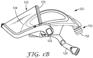
- the respirator system 100 includes a headgear article 120 , which includes a visor 122 and a head covering member 124 .
- the visor 122 is pivotally attached to the head covering member 124 via pivot mechanism 123, such that the visor may have a lowered position ( Figure 1A ), a raised position ( Figure 1B ) and various intermediate positions. Any suitable pivoting mechanism is within the scope of the present disclosure.
- the visor 122 includes a transparent member, which may be made of any suitable transparent material, such as a plastic material.
- the visor 122 includes a generally curved lens 122a and a lens frame 122b.
- Lens frame 122b supports lens 122a and facilitates pivoting of the visor 122 via pivot mechanism 123 .
- the curved lens 122a may be characterized by a cylindrical curvature with a spherical or an elliptical cross-section.
- the visor 122 includes a seal 125 attached to the lens 122a , the lens frame 122b or both. Seal 125 typically engages frontal area of the head covering member 124 , when visor 122 is in its lowered or closed position ( Figure 1A ). In some embodiments, the seal may be fluid tight, e.g., air tight.
- the head covering member 124 typically includes an outer shell that has sufficient structural integrity to retain its desired shape (and the shape of other layers that are supported by it) under normal handling.
- the head covering member 124 includes a shape-retaining outer shell, which substantially retains its shape after any deforming forces have ceased.
- the head covering member 124 is configured to resist impact.
- impact resistance exists where the head covering member absorbs at least a certain amount of mechanical energy from impact that would otherwise reach a user's head.
- Exemplary materials suitable for use in a head covering member include, without limitation, high density polyethylene, polypropylene, nylon, polycarbonate, ABS, styrene. Aluminum, fiber reinforced plastics, laminated paper products could also be used.
- the head covering member 124 has at least one opening 130 formed therein.
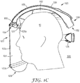
- the opening 130 is configured to provide fluid communication between an interior zone 102 (shown in Figure 1C ), defined by the headgear article 120 and a user's head 10 , and environment outside the headgear article.
- a layer of filter material may be disposed in the opening such that it separates the interior zone 102 from the environment outside the headgear article 120 .
- the layer of filter material would typically include one or more layers of material, which layer(s) is adapted for the primary purpose of removing contaminants (such as particles) from an air stream that passes through it, while allowing the passage of hot, moist air from above the wearer's head into the outside environment.
- a panel 140 is configured such that it can be disposed over the first opening and removably attached to the head covering member 124 , as described in more detail below in connection with Figures 2A -3B .
- the embodiment of the present invention includes two openings, such as 130 , and panels, such as 140 , configured to be removably attached thereto.
- Two removable panels may include an impact resistant material.
- the headgear article 120 of the respirator system 100 also may define a breathing zone 104 in the interior thereof as a subsection of the interior zone 102 .
- the breathing zone 104 is located between the visor 122 and the wearer's face.
- the breathing zone 104 is also defined by the face seal 126 .
- a breathing zone seal 127 may be used to separate the breathing zone 104 from the remainder of the interior zone 102 .
- the remainder of the interior zone 102 resides between the head covering member 124 and the top of the user's head.
- Clean air can be provided into the breathing zone 104 from any suitable source of clean air.
- the wearer breathes the air and exhales it back into the breathing zone.
- This exhaled air, along with excess clean air that is forced into the breathing zone, may exit the breathing zone through openings or through any other suitable route.
- cleaning air means atmospheric ambient air that has been filtered or air supplied from an independent source.
- Cylean air source means an apparatus, such as a filtering unit, compressed air source or a tank, that is capable of providing a supply of clean, breathable air for the user of the respirator system.
- the headgear article 120 may also include a face seal 126 and a suspension system 128 .
- the suspension system 128 serves to mount and support the headgear article 120 on a user's head, and it may be adjustable and typically includes a headband 128a configured to be disposed across a user's forehead.
- the face seal 126 is typically configured as to engage a wearer's face and aid in separating the breathing zone 104 from the outside environment.
- the face seal 126 may be permanently or removably attached to the headgear article 120 .
- the face seal 126 is attached, e.g., removably attached, to the lens frame 122b .
- the face seal 126 is made of a soft material due to the need to put it in contact with a user's skin, such as a woven or non-woven material, e.g., fabric.
- the outer periphery 126a of the face seal 126 is constructed to be disposed at least in part under the user's chin.
- the face seal 126 may be at least partially elastic, so that it could move with the user's jaw when the user talks and fit securely about the user's face after being stretched.
- the face seal 126 has an elastic member disposed along the periphery 126a of the face seal 126 and characterized by at least a certain degree of sealing effectiveness or integrity that reduces or minimizes the leakage of air into the breathing zone.
- the face seal 126 may include an elastic band (not shown) that can be made from any suitable material, such as SpandexTM or the like.
- the face seal 126 itself may have elastic properties.
- the face seal 126 may include one or more openings in its bottom portion 126b .
- the openings allow the breathable air delivered to the head covering member to exit upon exhaling.
- the bottom portion 126b may include relatively air permeable material that will allow air to escape.
- Other approaches for allowing air out of the respirator system 100 may be used with exemplary embodiments of the present disclosure.
- the respirator system 100 further includes a clean air supply system 150 which includes an inlet 152 configured for connection to a source of clean air 158 and an outlet 154 (shown in Figure 1C ) disposed within the breathing zone, preferably proximate a user's face.
- the clean air supply system 150 includes an air duct 156 , connecting the inlet 152 and the outlet 154 .
- the clean air supply system may further include a diverter 155 disposed in the outlet 154 and configured to allow the user to alter the direction and/or amount of air flow into the breathing zone 104 .
- a diverter 155 can be a moveable structure disposed adjacent the outlet 155 and that determines the flow direction of air exiting the outlet, dependent upon the position of the structure relative to the outlet.
- the outlet 154 may be adjustable between at least a first outlet configuration wherein the air flow from the outlet is directed in a first direction and at least a second outlet configuration wherein the air flow from the outlet is directed in a second, different direction.
- the breathing zone seal 127 may be on one end permanently or removably attached to the head covering member 124, for example, adjacent the outlet 154 , and on another end it may be permanently or removably attached to the headband 128a.
- the breathing zone seal 127 may be made from the same type of material as the face seal 126 or from another suitable material, such as foam.
- the inlet 152 can be connected to the source of clean air 170 by a hose 160 .
- the source of clean air may be an air exchange apparatus, which is an apparatus for providing a finite breathing zone volume around the head of a user in which air can be exchanged in conjunction with the user's breathing cycle.
- a respirator system utilizing an air exchange apparatus is a Powered Air Purifying Respirator" (PAPR), which is a powered system having a blower to force ambient air through air-purifying elements to an inlet 152 of the clean air supply system 150 .
- PAPR Powered Air Purifying Respirator
- the present disclosure is not limited thereto and may include any other suitable air supply system, including but not limited to negative pressure systems.
- Other exemplary air supply systems may include, without limitation, any suitable supplied air system or a compressed air system, such as a self contained breathing apparatus (SCBA).
- SCBA self contained breathing apparatus
- the inlet opening 152 may be positioned in the back of the headgear article 120 .
- An air inlet fluid coupling arrangement (not shown) may be connectable to the hose 160 , which, in turn, may be connected to the clean air supply 170 .
- air that enters through the inlet opening 152 is allowed to pass into the breathing zone through the outlet 154 and circulate between the visor 122 and a user's face.
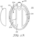
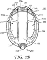
- Figures 2A and 2B show top and bottom views, respectively, of a headgear article 220 in accordance with embodiments of the present invention.
- the headgear article includes a head covering member 224 having an outer shell with a first opening 232 and a second opening 234 formed therein.
- Figure 2A shows an outer surface of the head covering member 224
- Figure 2B shows an inner surface of the head covering member 224.
- the first and second openings 232 and 234 are configured to provide fluid communication between an interior zone defined by the headgear article 220 and environment outside the headgear article.
- a layer of filter material 262a , 262b may be disposed in one or both of the openings 232 and 234 , such that the layer of filter material separates the interior zone from the environment outside the headgear article 220 .
- the filter material may be attached to the head covering member 224 in any suitable manner.
- a first panel 242 is disposed over the first opening 232 and removably attached to the head covering member 224 .
- a second panel 244 is disposed over the second opening 234 and removably attached to the head covering member 224 .
- Figure 2A shows outer surfaces of the removable panels 242 and 244 , while Figure 2B shows their inner surfaces.
- Figure 2A also shows the first panel 242 disengaged from the first opening 232 , while the second panel 244 is shown as attached to the head covering member 224 to cover the second opening 234 .
- Figure 2B shows the first and second panels 242 and 242 attached to the head covering member 224 to cover the first and second openings 232 and 234 .
- one or more removable panels 242 and 244 are configured to cover at least a portion of the outer surface of the head covering member 224 .
- removable panels e.g., 242
- the removable panel 242 is configured to not only cover the opening but also at least the area of the outer surface of the head covering member 224 that is adjacent to an edge of the opening.
- the removable panel 242 is configured to cover at least the area 233a of the outer surface of the head covering member 224 that is adjacent to an edge of the opening 232 and surrounds the opening 232 .
- the removable panel 242 is also configured to cover an additional area 233b of the outer surface of the head covering member 224 .
- one or more removable panels are disposed such that at least a substantial portion of the outer surface of the panel is disposed to cover the opening.
- a clean air supply system 250 is attached to the head covering member 224 .
- the clean air supply system includes an air duct 256 having an inlet 252 configured for connection to a source of clean air and an outlet disposed within the breathable zone.
- the outlet is disposed in the proximity of the user's face.
- the air duct 256 is disposed between the first opening 232 and the second opening 234 .
- Figure 2B shows an outlet that includes a central opening 254a and a pair of side openings 254b and 254c .
- the central opening 254a includes a diverter 255 .
- the diverter 255 is a panel that extends across the central opening 254a and is pivotally mounted adjacent thereto.
- the diverter 255 can be sized to completely cover the central opening 254a , in which case the flow of clean air is delivered into the breathing zone through the side openings 254b and 254c .
- the exemplary panel has side projections that are pivotally received within short walls 257 adjacent to the outlet and that separate the central opening 254a from the side openings 254b and 254c .
- the diverter 255 includes an actuator 259 projecting therefrom.
- Movement of the actuator 259 causes movement of the diverter 255 .
- the direction of air flow exiting the central opening 254a is changed so that it may be directed in a first direction or in a second, different direction or another direction selected by a user.
- Figure 2B also illustrates an exemplary mechanism for attaching a breathing zone seal to the head covering member 220 .
- the exemplary mechanism is a ridge 227 disposed in the frontal portion of the head covering member 220 and projecting from its inner surface.
- the ridge 227 is typically configured to aid in isolating the breathing zone of the headgear article from the remainder of the interior zone.
- the ridge 227 is configured as a wall projecting from the inner surface of the head covering member 220 that forms a part of the boundary between the breathing zone and the remainder of the interior zone.
- the exemplary ridge 227 may include a groove 227a for receiving and housing one end of the breathing zone seal. To facilitate attachment, the end of the breathing zone seal received in the groove may be shape-stable, for example, rubberized or made of a shape-stable polymeric material.
- Figures 3A and 3B show bottom partial views of an exemplary head covering member 324 demonstrating in detail removable attachment of the panel 342 to an edge (e.g., 332a, 332b ) of the opening 332 .
- Figure 3A shows the panel 342 with two retaining members 410 and 420 configured to removably attach to an edge of the opening 332 .
- Other exemplary embodiments of removable panels may have only one retaining member or more than two retaining members.
- retaining members 410 and 420 are elongated latch members. The one or more latch members can be configured to form a snap-fit with an edge of the opening 332 .
- the latch members may be formed from a resilient material, such that they are capable of bending when a force is applied and then recovering its original shape when the force is released.
- One or more retaining members e.g., 410, 420
- Figure 3B shows a cross-sectional view of a panel 342 removably attached to edges 332a , 332b of an opening 332 via retaining members 410 , 420.
- Each exemplary retaining member 410 , 420 includes a ledge 414 , 424.
- the ledge 414 , 424 cooperates with an opposing peripheral edge of the panel 412,422 to removably retain an edge 332a, 332b of the opening 332 therebetween.
- at least one retaining member 410, 420 may be configured such that at least a portion thereof (e.g., a portion of the ledge 414, 424 ) is in contact with the inner surface of the head covering member 324 .
- the at least one retaining member 410, 420 also may be configured such that at least a portion thereof (e.g., 412, 422 ) is in contact with the outer surface of the head covering member 324 .
- retaining members are within the scope of the present disclosure.
- suitable removable fastening systems include hook and loop systems, clips, screws, and adhesives, such as repositionable adhesives.
- rotatable latches may be used as one or more retaining members.
- Rotatable latches typically utilize an arm rotatably mountable on the removable panel or the head covering member. The arm can be pivoted to extend across the edge of the opening and the removable panel to retain the panel to the head covering member. If the rotatable latch is mounted onto the removable panel, it may be rotated to extend under the lower surface of the head covering member and thereby retain the removable panel to the head covering member.
- the removable panel preferably further includes at least one locating feature to aid proper alignment of the removable panel with respect to the opening.
- the panel 342 includes one or more locating ridges 430 , 440 , which have shapes that mate with the periphery of the opening 332 to allow only one orientation in which the retaining members 410 , 420 can interlock with the edges of the opening 332.
- Other types and configurations of locating features are also within the scope of the present disclosure, including but not limited to discrete protrusions or one or more tabs, slots, pegs and holes.
Claims (13)
- Kopfbedeckungsartikel (120, 220), umfassend:ein Visier (122), wobei der Kopfbedeckungsartikel eine Innenzone (102), umfassend eine Atmungszone (104) zwischen dem Visier und dem Gesicht eines Trägers, definiert;ein Kopfabdeckelement (124, 224, 324) mit einer ersten Öffnung (130, 232, 332) und einer zweiten Öffnung (130, 234) darin ausgebildet, wobei die erste Öffnung einen Rand (332a, 332b) aufweist und die zweite Öffnung einen Rand aufweist;eine erste Platte (140, 242, 342) mit einer Außenoberfläche, die so angeordnet ist, dass ein wesentlicher Abschnitt der Außenoberfläche über der ersten Öffnung angeordnet ist, wobei die erste Platte ferner mindestens ein Halteelement (410, 420) umfasst, das konfiguriert ist, um entfernbar am Rand der ersten Öffnung befestigt zu werden;eine zweite Platte (140, 244), die über der zweiten Öffnung (130, 234) angeordnet und entfernbar an dem Kopfabdeckelement (124, 224, 324) befestigt ist; undeinen Luftkanal (156, 256), der zwischen der ersten und der zweiten Öffnung angeordnet ist, wobei der eine Luftkanal einen zur Verbindung mit einer Reinluftquelle konfigurierten Einlass (152, 252) und einen innerhalb der Innenzone (102) angeordneten Auslass (154, 254a, 245b, 254c) umfasst.
- Kopfbedeckungsartikel (120, 220) nach Anspruch 1, der ferner eine Atemzonendichtung (127, 227) umfasst, die die Atemzone (104) von dem Rest der Innenzone (102) trennt.
- Kopfbedeckungsartikel (120, 220) nach Anspruch 1, wobei das Kopfabdeckelement (124, 224, 324) eine Außenoberfläche aufweist und die erste Platte (140, 242, 342) über mindestens einem Abschnitt der Außenoberfläche angeordnet ist.
- Kopfbedeckungsartikel (120) nach Anspruch 3, wobei das Kopfabdeckelement (124, 224, 324) eine Innenoberfläche aufweist und das mindestens eine Halteelement (410, 420) so konfiguriert ist, dass mindestens ein Abschnitt davon in Kontakt mit der Innenoberfläche steht.
- Kopfbedeckungsartikel (120) nach Anspruch 1, wobei die erste Platte (140, 242, 342) mindestens zwei längliche Verriegelungselemente umfasst.
- Kopfbedeckungsartikel (120) nach Anspruch 1, wobei die erste Platte (140, 242, 342) ferner mindestens ein Positionierungsmerkmal umfasst.
- Atemschutzsystem (100), umfassend den Kopfbedeckungsartikel (120, 220) nach Anspruch 1 und ein Reinluftzufuhrsystem (150, 250), das den Einlass (152, 252) und den Auslass (154, 254a, 245b, 254c) des Luftkanals (156, 256) umfasst.
- Atemschutzsystem (100) nach Anspruch 7, ferner umfassend eine Schicht (262a) aus Filtermaterial, die in der ersten Öffnung (130, 232, 332) angeordnet ist.
- Atemschutzsystem (100) nach Anspruch 7, das ferner eine Reinluftquelle umfasst.
- Atemschutzsystem (100) nach Anspruch 7, wobei das Kopfabdeckelement (124, 224, 324) ein schlagzähes Material umfasst.
- Atemschutzsystem (100) nach Anspruch 7, wobei die erste Platte (140, 242, 342) und die zweite Platte (140, 244) ein schlagzähes Material umfassen.
- Atemschutzsystem (100) nach Anspruch 7, wobei die erste Platte (140, 242, 342) und die zweite Platte (140, 244) mindestens eines von Folgenden umfassen: reflektierendes Material, eine farbige Schicht und eine gemusterte Schicht.
- Atemschutzsystem (100) nach Anspruch 7, ferner umfassend eine Schicht aus Filtermaterial (262a, 262b), die in jeder der ersten und zweiten Öffnungen (130, 232, 234, 332) angeordnet ist.
Priority Applications (1)
| Application Number | Priority Date | Filing Date | Title |
|---|---|---|---|
| PL09727128T PL2271407T3 (pl) | 2008-04-04 | 2009-03-02 | System oddechowy zawierający składany element osłaniający głowę |
Applications Claiming Priority (2)
| Application Number | Priority Date | Filing Date | Title |
|---|---|---|---|
| US4230408P | 2008-04-04 | 2008-04-04 | |
| PCT/US2009/035629 WO2009123809A2 (en) | 2008-04-04 | 2009-03-02 | Respirator system including convertible head covering member |
Publications (3)
| Publication Number | Publication Date |
|---|---|
| EP2271407A2 EP2271407A2 (de) | 2011-01-12 |
| EP2271407A4 EP2271407A4 (de) | 2015-04-29 |
| EP2271407B1 true EP2271407B1 (de) | 2019-04-24 |
Family
ID=41136071
Family Applications (1)
| Application Number | Title | Priority Date | Filing Date |
|---|---|---|---|
| EP09727128.2A Active EP2271407B1 (de) | 2008-04-04 | 2009-03-02 | Atemgerätsystem mit einem umwandelbaren kopfabdeckungselement |
Country Status (7)
| Country | Link |
|---|---|
| US (1) | US8534279B2 (de) |
| EP (1) | EP2271407B1 (de) |
| JP (1) | JP5320457B2 (de) |
| CN (1) | CN101980752B (de) |
| AU (1) | AU2009232309B2 (de) |
| PL (1) | PL2271407T3 (de) |
| WO (1) | WO2009123809A2 (de) |
Families Citing this family (39)
| Publication number | Priority date | Publication date | Assignee | Title |
|---|---|---|---|---|
| EP2209530B1 (de) * | 2007-10-05 | 2015-02-25 | 3M Innovative Properties Company | Atemschutzgerätschlauch und anbringvorrichtung und -verfahren |
| GB2505484A (en) * | 2012-08-31 | 2014-03-05 | 3M Innovative Properties Co | Powered exhaust apparatus for a personal protection respiratory device |
| US8701212B2 (en) | 2012-09-26 | 2014-04-22 | 3M Innovative Properties Company | Elongated guide, and visor removably mountable thereto |
| US10149511B2 (en) | 2012-09-28 | 2018-12-11 | Matscitechno Licensing Company | Protective headgear system |
| US9775397B2 (en) | 2013-03-15 | 2017-10-03 | 3M Innovative Properties Company | Elongated guide, and visor removably mountable thereto |
| USD755953S1 (en) * | 2013-11-04 | 2016-05-10 | Facecover Sweden Ab | Breathing mask |
| US11659882B2 (en) | 2014-02-21 | 2023-05-30 | Matscitechno Licensing Company | Helmet padding system |
| US11253771B2 (en) | 2014-02-21 | 2022-02-22 | Matscitechno Licensing Company | Helmet padding system |
| US11744312B2 (en) | 2014-02-21 | 2023-09-05 | Matscitechno Licensing Company | Helmet padding system |
| US10993496B2 (en) | 2014-02-21 | 2021-05-04 | Matscitechno Licensing Company | Helmet padding system |
| US11730222B2 (en) | 2014-02-21 | 2023-08-22 | Matscitechno Licensing Company | Helmet padding system |
| USD800298S1 (en) * | 2014-04-16 | 2017-10-17 | Sata Gmbh & Co. Kg | Air block for respirator |
| USD774702S1 (en) * | 2014-08-26 | 2016-12-20 | Sata Gmbh & Co. Kg | Respirator helmet |
| DE102014019204B4 (de) * | 2014-12-19 | 2018-05-17 | Dräger Safety AG & Co. KGaA | Kopfschutzvorrichtung und Atemschutzvorrichtung |
| USD777381S1 (en) * | 2015-04-24 | 2017-01-24 | Daqri, Llc | Headwear |
| EP3302117A4 (de) * | 2015-06-03 | 2019-01-16 | Matscitechno Licensing Company | Helmpolsterungssystem |
| USD825739S1 (en) * | 2015-08-13 | 2018-08-14 | Jsp Limited | Modular powered respirator |
| US10610708B2 (en) * | 2016-06-23 | 2020-04-07 | 3M Innovative Properties Company | Indicating hazardous exposure in a supplied air respirator system |
| US9848666B1 (en) | 2016-06-23 | 2017-12-26 | 3M Innovative Properties Company | Retrofit sensor module for a protective head top |
| US11023818B2 (en) | 2016-06-23 | 2021-06-01 | 3M Innovative Properties Company | Personal protective equipment system having analytics engine with integrated monitoring, alerting, and predictive safety event avoidance |
| US9998804B2 (en) | 2016-06-23 | 2018-06-12 | 3M Innovative Properties Company | Personal protective equipment (PPE) with analytical stream processing for safety event detection |
| USD802117S1 (en) * | 2016-07-30 | 2017-11-07 | Rpb Safety Llc | Respirator helmet |
| US11131310B1 (en) * | 2017-03-07 | 2021-09-28 | Eric D. Emery | Airflow assembly |
| AU201714179S (en) * | 2017-07-06 | 2017-09-27 | Sundstrom Safety Ab | Protective mask |
| TWD195690S (zh) * | 2017-09-18 | 2019-02-01 | 英商Jsp有限公司 | 保護頭盔 |
| EP3697357A4 (de) * | 2017-10-16 | 2021-07-07 | Gentex Corporation | Modulares atemschutzsystem |
| USD881380S1 (en) | 2017-10-16 | 2020-04-14 | Gentex Corporation | Respirator |
| JP1631967S (de) | 2018-04-04 | 2019-05-20 | ||
| USD899698S1 (en) | 2018-04-04 | 2020-10-20 | Tecmen Electronics Co., Ltd. | Protective helmet |
| USD900399S1 (en) | 2018-04-04 | 2020-10-27 | Tecmen Electronics Co., Ltd. | Protective helmet |
| USD876530S1 (en) | 2018-09-26 | 2020-02-25 | Tecmen Electronics Co., Ltd. | Auto darkening welding goggle |
| USD959757S1 (en) * | 2019-10-23 | 2022-08-02 | Sundström Safety Aktiebolag | Helmet liner |
| USD931549S1 (en) * | 2020-03-11 | 2021-09-21 | Lincoln Global, Inc | Chin guard for a face shield |
| US11540577B2 (en) | 2020-03-12 | 2023-01-03 | Matscitechno Licensing Company | Helmet system |
| US11540578B2 (en) | 2020-03-12 | 2023-01-03 | Matscitechno Licensing Company | Helmet system |
| NL2025424B1 (en) * | 2020-04-24 | 2021-11-02 | Stichting Air Wave Org | Personal protection equipment, airflow adapter part and outflow part |
| USD936908S1 (en) * | 2020-06-09 | 2021-11-23 | Lincoln Global, Inc. | Chin guard for a face shield |
| GB2597289A (en) * | 2020-07-20 | 2022-01-26 | Bae Systems Plc | Improvements in air delivery devices |
| USD955058S1 (en) * | 2020-07-24 | 2022-06-14 | Rpb Safety, Llc | Cap with duct |
Family Cites Families (44)
| Publication number | Priority date | Publication date | Assignee | Title |
|---|---|---|---|---|
| USD250496S (en) * | 1976-08-08 | 1978-12-12 | Raymond Odell | Head seal for an anti-dust helmet |
| GB1576410A (en) * | 1976-12-30 | 1980-10-08 | Owen & Co Bow Ltd Charles | Safety helmets |
| US4280491A (en) * | 1980-03-07 | 1981-07-28 | Minnesota Mining And Manufacturing Company | Powered air respirator |
| FR2532552B1 (fr) * | 1982-09-03 | 1986-01-24 | Galet Adrien | Casque de protection, notamment utilisable avec un masque respiratoire |
| JPS62180462A (ja) | 1986-02-04 | 1987-08-07 | Ricoh Co Ltd | 音声入力かな漢字変換装置 |
| JPH0522191Y2 (de) * | 1986-05-06 | 1993-06-07 | ||
| US4995117A (en) * | 1988-11-04 | 1991-02-26 | James A. Mirage | (Airlock) bicycle helment with adjustable ventilation systems and accessories |
| JPH05168724A (ja) | 1991-12-21 | 1993-07-02 | Yutaka Yasuda | 防塵ヘルメット |
| US5533500A (en) * | 1992-03-04 | 1996-07-09 | Her-Mou; Lin | Helmet with an air filtering device |
| DK0652790T3 (de) * | 1992-07-31 | 1997-02-24 | Mine Safety Appliances Co | |
| US5557495A (en) * | 1994-09-29 | 1996-09-17 | Harris Corporation | Variable capacitor and method |
| US6014971A (en) * | 1997-08-15 | 2000-01-18 | 3M Innovative Properties Company | Protective system for face and respiratory protection |
| JPH11124719A (ja) * | 1997-10-22 | 1999-05-11 | Shiiraizu Corporation:Kk | 保護帽 |
| JP2962700B2 (ja) * | 1998-01-22 | 1999-10-12 | オージーケー販売株式会社 | ヘルメット装置 |
| USD420771S (en) * | 1998-03-10 | 2000-02-15 | 3M Innovative Properties Company | Top portion of a protective respiratory helmet |
| US6102033A (en) * | 1998-03-10 | 2000-08-15 | 3M Innovative Properties Company | Attachment system for replacement helmet respirator lens |
| US6035451A (en) * | 1998-03-10 | 2000-03-14 | Minnesota Mining And Manufacturing Company | Protective helmet system with cam for attaching first and second face shields thereto |
| US6122773A (en) * | 1999-04-15 | 2000-09-26 | Katz; Marc | Ventilated hardhat |
| USD444269S1 (en) * | 1999-07-21 | 2001-06-26 | Matthew Jeffreys | Helmet |
| USD443394S1 (en) * | 2000-02-17 | 2001-06-05 | Optical Engineering Company, Llc | Safety helmet |
| JP2002004127A (ja) * | 2000-06-20 | 2002-01-09 | Oshima Denki Seisakusho:Kk | ヘルメット |
| KR100431116B1 (ko) | 2000-08-02 | 2004-05-20 | 주식회사 팜텍 | 열전반도체를 이용한 냉각방식의 방제용 헬멧 |
| AU2002335616B2 (en) * | 2001-04-23 | 2006-11-02 | Scott Technologies, Inc. | Respirator mask |
| USD453056S1 (en) * | 2001-05-10 | 2002-01-22 | Louis Garneau Sports Inc. | Sub-freezing weather helmet |
| US6418564B1 (en) * | 2001-05-11 | 2002-07-16 | Patrick Sheridan | Two piece helmet with optional airbag |
| CA2422392A1 (en) * | 2002-03-12 | 2003-09-12 | Bombardier Inc. | Cold-weather helmet with breathing mask breathing air from inside the helmet |
| GB2387102B (en) * | 2002-04-04 | 2005-12-07 | Tunnard Mitchell | Modular helmet |
| USD485947S1 (en) | 2002-05-06 | 2004-01-27 | Bayerische Motoren Werke Aktiengesellschaft | Surface configuration of a helmet |
| US20040064873A1 (en) * | 2002-05-29 | 2004-04-08 | Muskovitz David T. | In-mold protective helmet having integrated ventilation system |
| US7275535B1 (en) * | 2003-06-23 | 2007-10-02 | Robert Brockman | Respiration hood useful in biological, radiological and chemical emergencies |
| US6973676B1 (en) * | 2003-09-02 | 2005-12-13 | Elwood Jesse Bill Simpson | Protective helmet with integral air supply |
| USD499214S1 (en) * | 2003-09-02 | 2004-11-30 | Polison Corporation | Protective helmet |
| USD503497S1 (en) * | 2003-09-10 | 2005-03-29 | Bacou-Dalloz Eye & Face Protection, Inc. | Protective face shield molded lens |
| USD504195S1 (en) * | 2003-09-10 | 2005-04-19 | Bacou-Dalloz Eye & Face Protection, Inc. | Protective face shield frame |
| USD503498S1 (en) * | 2003-09-10 | 2005-03-29 | Bacou-Dalloz Eye & Face Protection, Inc. | Protective face shield assembly |
| US7007306B2 (en) * | 2003-11-04 | 2006-03-07 | Bacou-Dalloz Eye & Face Protection, Inc. | Face shield assembly |
| CN2669905Y (zh) * | 2003-12-09 | 2005-01-12 | 余红民 | 正压式呼吸防尘防毒装置 |
| CA2573640C (en) * | 2004-07-14 | 2010-09-28 | Sport Maska Inc. | Adjustable helmet shell |
| US7636954B2 (en) * | 2004-08-03 | 2009-12-29 | Bell Sports, Inc. | System for accommodating helmet accessories |
| USD520684S1 (en) * | 2004-09-03 | 2006-05-09 | Optical Engineering Company, Llc | Protective helmet |
| USD517745S1 (en) * | 2004-11-12 | 2006-03-21 | 3M Innovative Properties Company | Chin portion of welding helmet visor |
| US20060107431A1 (en) * | 2004-11-12 | 2006-05-25 | Curran Desmond T | Supplied air helmet having a knitted face seal |
| USD539485S1 (en) * | 2006-03-14 | 2007-03-27 | Otos Tech Co., Ltd. | Mask for protecting a face |
| USD590547S1 (en) * | 2008-04-03 | 2009-04-14 | 3M Innovative Properties Company | Headgear article having recessed portions |
-
2009
- 2009-03-02 CN CN2009801115739A patent/CN101980752B/zh not_active Expired - Fee Related
- 2009-03-02 US US12/934,288 patent/US8534279B2/en active Active
- 2009-03-02 AU AU2009232309A patent/AU2009232309B2/en not_active Ceased
- 2009-03-02 PL PL09727128T patent/PL2271407T3/pl unknown
- 2009-03-02 JP JP2011503006A patent/JP5320457B2/ja not_active Expired - Fee Related
- 2009-03-02 EP EP09727128.2A patent/EP2271407B1/de active Active
- 2009-03-02 WO PCT/US2009/035629 patent/WO2009123809A2/en active Application Filing
Non-Patent Citations (1)
| Title |
|---|
| None * |
Also Published As
| Publication number | Publication date |
|---|---|
| WO2009123809A3 (en) | 2010-03-04 |
| EP2271407A4 (de) | 2015-04-29 |
| US20110048416A1 (en) | 2011-03-03 |
| JP5320457B2 (ja) | 2013-10-23 |
| CN101980752A (zh) | 2011-02-23 |
| JP2011516155A (ja) | 2011-05-26 |
| US8534279B2 (en) | 2013-09-17 |
| AU2009232309A1 (en) | 2009-10-08 |
| CN101980752B (zh) | 2012-07-11 |
| PL2271407T3 (pl) | 2019-09-30 |
| AU2009232309B2 (en) | 2011-04-07 |
| WO2009123809A2 (en) | 2009-10-08 |
| EP2271407A2 (de) | 2011-01-12 |
Similar Documents
| Publication | Publication Date | Title |
|---|---|---|
| EP2271407B1 (de) | Atemgerätsystem mit einem umwandelbaren kopfabdeckungselement | |
| EP3061502B1 (de) | Stromloser atemschützende haube und maske mit schutz vor beschlagen der sichtscheibe | |
| EP1061822B1 (de) | Gesichtsdichtung für atemschutzgerät | |
| US5577495A (en) | Helmet respirator apparatus | |
| EP2209530B1 (de) | Atemschutzgerätschlauch und anbringvorrichtung und -verfahren | |
| EP2131928B1 (de) | Luftzufuhrgerät für atemgeräthaube | |
| JP5062619B2 (ja) | 保護ヘッドギアシステム | |
| JP5836348B2 (ja) | レスピレーターの流量制御装置及び方法 | |
| EP1613398B1 (de) | Starre luftleitung für atemschutzgerätehauben und -helme | |
| JP2008520271A (ja) | 摩擦係合する給気式ヘルメットフェースシール | |
| WO2015005955A1 (en) | Respiratory hood capable of being worn with external head gear | |
| US20210392989A1 (en) | Filtered protective mask for a helmet | |
| CN113811367B (zh) | 面罩颏部维持特征部 | |
| US20220110380A1 (en) | Face mask with adjustable nose fit | |
| WO2021089626A1 (en) | Head mountable air respirator | |
| KR20210026421A (ko) | 전면 호흡 보호 장치 |
Legal Events
| Date | Code | Title | Description |
|---|---|---|---|
| PUAI | Public reference made under article 153(3) epc to a published international application that has entered the european phase |
Free format text: ORIGINAL CODE: 0009012 |
|
| 17P | Request for examination filed |
Effective date: 20101029 |
|
| AK | Designated contracting states |
Kind code of ref document: A2 Designated state(s): AT BE BG CH CY CZ DE DK EE ES FI FR GB GR HR HU IE IS IT LI LT LU LV MC MK MT NL NO PL PT RO SE SI SK TR |
|
| AX | Request for extension of the european patent |
Extension state: AL BA RS |
|
| DAX | Request for extension of the european patent (deleted) | ||
| A4 | Supplementary search report drawn up and despatched |
Effective date: 20150330 |
|
| RIC1 | Information provided on ipc code assigned before grant |
Ipc: A62B 18/02 20060101AFI20150324BHEP Ipc: A62B 7/12 20060101ALI20150324BHEP Ipc: A62B 9/00 20060101ALI20150324BHEP Ipc: A42B 3/28 20060101ALI20150324BHEP |
|
| STAA | Information on the status of an ep patent application or granted ep patent |
Free format text: STATUS: EXAMINATION IS IN PROGRESS |
|
| 17Q | First examination report despatched |
Effective date: 20170331 |
|
| GRAP | Despatch of communication of intention to grant a patent |
Free format text: ORIGINAL CODE: EPIDOSNIGR1 |
|
| STAA | Information on the status of an ep patent application or granted ep patent |
Free format text: STATUS: GRANT OF PATENT IS INTENDED |
|
| INTG | Intention to grant announced |
Effective date: 20181026 |
|
| GRAS | Grant fee paid |
Free format text: ORIGINAL CODE: EPIDOSNIGR3 |
|
| GRAA | (expected) grant |
Free format text: ORIGINAL CODE: 0009210 |
|
| STAA | Information on the status of an ep patent application or granted ep patent |
Free format text: STATUS: THE PATENT HAS BEEN GRANTED |
|
| AK | Designated contracting states |
Kind code of ref document: B1 Designated state(s): AT BE BG CH CY CZ DE DK EE ES FI FR GB GR HR HU IE IS IT LI LT LU LV MC MK MT NL NO PL PT RO SE SI SK TR |
|
| REG | Reference to a national code |
Ref country code: GB Ref legal event code: FG4D |
|
| REG | Reference to a national code |
Ref country code: CH Ref legal event code: EP |
|
| REG | Reference to a national code |
Ref country code: AT Ref legal event code: REF Ref document number: 1123426 Country of ref document: AT Kind code of ref document: T Effective date: 20190515 Ref country code: IE Ref legal event code: FG4D |
|
| REG | Reference to a national code |
Ref country code: DE Ref legal event code: R096 Ref document number: 602009058026 Country of ref document: DE |
|
| REG | Reference to a national code |
Ref country code: SE Ref legal event code: TRGR |
|
| REG | Reference to a national code |
Ref country code: NL Ref legal event code: MP Effective date: 20190424 |
|
| REG | Reference to a national code |
Ref country code: LT Ref legal event code: MG4D |
|
| PG25 | Lapsed in a contracting state [announced via postgrant information from national office to epo] |
Ref country code: NL Free format text: LAPSE BECAUSE OF FAILURE TO SUBMIT A TRANSLATION OF THE DESCRIPTION OR TO PAY THE FEE WITHIN THE PRESCRIBED TIME-LIMIT Effective date: 20190424 |
|
| PG25 | Lapsed in a contracting state [announced via postgrant information from national office to epo] |
Ref country code: LT Free format text: LAPSE BECAUSE OF FAILURE TO SUBMIT A TRANSLATION OF THE DESCRIPTION OR TO PAY THE FEE WITHIN THE PRESCRIBED TIME-LIMIT Effective date: 20190424 Ref country code: FI Free format text: LAPSE BECAUSE OF FAILURE TO SUBMIT A TRANSLATION OF THE DESCRIPTION OR TO PAY THE FEE WITHIN THE PRESCRIBED TIME-LIMIT Effective date: 20190424 Ref country code: ES Free format text: LAPSE BECAUSE OF FAILURE TO SUBMIT A TRANSLATION OF THE DESCRIPTION OR TO PAY THE FEE WITHIN THE PRESCRIBED TIME-LIMIT Effective date: 20190424 Ref country code: NO Free format text: LAPSE BECAUSE OF FAILURE TO SUBMIT A TRANSLATION OF THE DESCRIPTION OR TO PAY THE FEE WITHIN THE PRESCRIBED TIME-LIMIT Effective date: 20190724 Ref country code: PT Free format text: LAPSE BECAUSE OF FAILURE TO SUBMIT A TRANSLATION OF THE DESCRIPTION OR TO PAY THE FEE WITHIN THE PRESCRIBED TIME-LIMIT Effective date: 20190824 Ref country code: HR Free format text: LAPSE BECAUSE OF FAILURE TO SUBMIT A TRANSLATION OF THE DESCRIPTION OR TO PAY THE FEE WITHIN THE PRESCRIBED TIME-LIMIT Effective date: 20190424 |
|
| PG25 | Lapsed in a contracting state [announced via postgrant information from national office to epo] |
Ref country code: BG Free format text: LAPSE BECAUSE OF FAILURE TO SUBMIT A TRANSLATION OF THE DESCRIPTION OR TO PAY THE FEE WITHIN THE PRESCRIBED TIME-LIMIT Effective date: 20190724 Ref country code: GR Free format text: LAPSE BECAUSE OF FAILURE TO SUBMIT A TRANSLATION OF THE DESCRIPTION OR TO PAY THE FEE WITHIN THE PRESCRIBED TIME-LIMIT Effective date: 20190725 Ref country code: LV Free format text: LAPSE BECAUSE OF FAILURE TO SUBMIT A TRANSLATION OF THE DESCRIPTION OR TO PAY THE FEE WITHIN THE PRESCRIBED TIME-LIMIT Effective date: 20190424 |
|
| REG | Reference to a national code |
Ref country code: AT Ref legal event code: MK05 Ref document number: 1123426 Country of ref document: AT Kind code of ref document: T Effective date: 20190424 |
|
| PG25 | Lapsed in a contracting state [announced via postgrant information from national office to epo] |
Ref country code: IS Free format text: LAPSE BECAUSE OF FAILURE TO SUBMIT A TRANSLATION OF THE DESCRIPTION OR TO PAY THE FEE WITHIN THE PRESCRIBED TIME-LIMIT Effective date: 20190824 |
|
| REG | Reference to a national code |
Ref country code: DE Ref legal event code: R097 Ref document number: 602009058026 Country of ref document: DE |
|
| PG25 | Lapsed in a contracting state [announced via postgrant information from national office to epo] |
Ref country code: EE Free format text: LAPSE BECAUSE OF FAILURE TO SUBMIT A TRANSLATION OF THE DESCRIPTION OR TO PAY THE FEE WITHIN THE PRESCRIBED TIME-LIMIT Effective date: 20190424 Ref country code: DK Free format text: LAPSE BECAUSE OF FAILURE TO SUBMIT A TRANSLATION OF THE DESCRIPTION OR TO PAY THE FEE WITHIN THE PRESCRIBED TIME-LIMIT Effective date: 20190424 Ref country code: AT Free format text: LAPSE BECAUSE OF FAILURE TO SUBMIT A TRANSLATION OF THE DESCRIPTION OR TO PAY THE FEE WITHIN THE PRESCRIBED TIME-LIMIT Effective date: 20190424 Ref country code: CZ Free format text: LAPSE BECAUSE OF FAILURE TO SUBMIT A TRANSLATION OF THE DESCRIPTION OR TO PAY THE FEE WITHIN THE PRESCRIBED TIME-LIMIT Effective date: 20190424 Ref country code: RO Free format text: LAPSE BECAUSE OF FAILURE TO SUBMIT A TRANSLATION OF THE DESCRIPTION OR TO PAY THE FEE WITHIN THE PRESCRIBED TIME-LIMIT Effective date: 20190424 Ref country code: SK Free format text: LAPSE BECAUSE OF FAILURE TO SUBMIT A TRANSLATION OF THE DESCRIPTION OR TO PAY THE FEE WITHIN THE PRESCRIBED TIME-LIMIT Effective date: 20190424 |
|
| PG25 | Lapsed in a contracting state [announced via postgrant information from national office to epo] |
Ref country code: IT Free format text: LAPSE BECAUSE OF FAILURE TO SUBMIT A TRANSLATION OF THE DESCRIPTION OR TO PAY THE FEE WITHIN THE PRESCRIBED TIME-LIMIT Effective date: 20190424 |
|
| PLBE | No opposition filed within time limit |
Free format text: ORIGINAL CODE: 0009261 |
|
| STAA | Information on the status of an ep patent application or granted ep patent |
Free format text: STATUS: NO OPPOSITION FILED WITHIN TIME LIMIT |
|
| PG25 | Lapsed in a contracting state [announced via postgrant information from national office to epo] |
Ref country code: TR Free format text: LAPSE BECAUSE OF FAILURE TO SUBMIT A TRANSLATION OF THE DESCRIPTION OR TO PAY THE FEE WITHIN THE PRESCRIBED TIME-LIMIT Effective date: 20190424 |
|
| 26N | No opposition filed |
Effective date: 20200127 |
|
| PGFP | Annual fee paid to national office [announced via postgrant information from national office to epo] |
Ref country code: GB Payment date: 20200219 Year of fee payment: 12 Ref country code: PL Payment date: 20200127 Year of fee payment: 12 Ref country code: SE Payment date: 20200310 Year of fee payment: 12 |
|
| PG25 | Lapsed in a contracting state [announced via postgrant information from national office to epo] |
Ref country code: SI Free format text: LAPSE BECAUSE OF FAILURE TO SUBMIT A TRANSLATION OF THE DESCRIPTION OR TO PAY THE FEE WITHIN THE PRESCRIBED TIME-LIMIT Effective date: 20190424 |
|
| PG25 | Lapsed in a contracting state [announced via postgrant information from national office to epo] |
Ref country code: MC Free format text: LAPSE BECAUSE OF FAILURE TO SUBMIT A TRANSLATION OF THE DESCRIPTION OR TO PAY THE FEE WITHIN THE PRESCRIBED TIME-LIMIT Effective date: 20190424 |
|
| REG | Reference to a national code |
Ref country code: CH Ref legal event code: PL |
|
| REG | Reference to a national code |
Ref country code: BE Ref legal event code: MM Effective date: 20200331 |
|
| PG25 | Lapsed in a contracting state [announced via postgrant information from national office to epo] |
Ref country code: LU Free format text: LAPSE BECAUSE OF NON-PAYMENT OF DUE FEES Effective date: 20200302 |
|
| PG25 | Lapsed in a contracting state [announced via postgrant information from national office to epo] |
Ref country code: LI Free format text: LAPSE BECAUSE OF NON-PAYMENT OF DUE FEES Effective date: 20200331 Ref country code: CH Free format text: LAPSE BECAUSE OF NON-PAYMENT OF DUE FEES Effective date: 20200331 Ref country code: IE Free format text: LAPSE BECAUSE OF NON-PAYMENT OF DUE FEES Effective date: 20200302 |
|
| PG25 | Lapsed in a contracting state [announced via postgrant information from national office to epo] |
Ref country code: BE Free format text: LAPSE BECAUSE OF NON-PAYMENT OF DUE FEES Effective date: 20200331 |
|
| GBPC | Gb: european patent ceased through non-payment of renewal fee |
Effective date: 20210302 |
|
| PG25 | Lapsed in a contracting state [announced via postgrant information from national office to epo] |
Ref country code: SE Free format text: LAPSE BECAUSE OF NON-PAYMENT OF DUE FEES Effective date: 20210303 Ref country code: GB Free format text: LAPSE BECAUSE OF NON-PAYMENT OF DUE FEES Effective date: 20210302 |
|
| PGFP | Annual fee paid to national office [announced via postgrant information from national office to epo] |
Ref country code: DE Payment date: 20220217 Year of fee payment: 14 |
|
| PG25 | Lapsed in a contracting state [announced via postgrant information from national office to epo] |
Ref country code: MT Free format text: LAPSE BECAUSE OF FAILURE TO SUBMIT A TRANSLATION OF THE DESCRIPTION OR TO PAY THE FEE WITHIN THE PRESCRIBED TIME-LIMIT Effective date: 20190424 Ref country code: CY Free format text: LAPSE BECAUSE OF FAILURE TO SUBMIT A TRANSLATION OF THE DESCRIPTION OR TO PAY THE FEE WITHIN THE PRESCRIBED TIME-LIMIT Effective date: 20190424 |
|
| PGFP | Annual fee paid to national office [announced via postgrant information from national office to epo] |
Ref country code: FR Payment date: 20220221 Year of fee payment: 14 |
|
| PG25 | Lapsed in a contracting state [announced via postgrant information from national office to epo] |
Ref country code: MK Free format text: LAPSE BECAUSE OF FAILURE TO SUBMIT A TRANSLATION OF THE DESCRIPTION OR TO PAY THE FEE WITHIN THE PRESCRIBED TIME-LIMIT Effective date: 20190424 |
|
| REG | Reference to a national code |
Ref country code: DE Ref legal event code: R119 Ref document number: 602009058026 Country of ref document: DE |
|
| PG25 | Lapsed in a contracting state [announced via postgrant information from national office to epo] |
Ref country code: FR Free format text: LAPSE BECAUSE OF NON-PAYMENT OF DUE FEES Effective date: 20230331 Ref country code: DE Free format text: LAPSE BECAUSE OF NON-PAYMENT OF DUE FEES Effective date: 20231003 |