EP2271388B1 - Dispositif de distribution de particules - Google Patents
Dispositif de distribution de particules Download PDFInfo
- Publication number
- EP2271388B1 EP2271388B1 EP09732550.0A EP09732550A EP2271388B1 EP 2271388 B1 EP2271388 B1 EP 2271388B1 EP 09732550 A EP09732550 A EP 09732550A EP 2271388 B1 EP2271388 B1 EP 2271388B1
- Authority
- EP
- European Patent Office
- Prior art keywords
- chamber
- dispenser
- fluid
- container
- particulate
- Prior art date
- Legal status (The legal status is an assumption and is not a legal conclusion. Google has not performed a legal analysis and makes no representation as to the accuracy of the status listed.)
- Active
Links
- 239000012530 fluid Substances 0.000 claims description 121
- 239000002775 capsule Substances 0.000 claims description 23
- 239000003814 drug Substances 0.000 claims description 18
- 230000002427 irreversible effect Effects 0.000 claims description 12
- 238000004891 communication Methods 0.000 claims description 11
- 239000000463 material Substances 0.000 description 14
- 239000007789 gas Substances 0.000 description 13
- 239000000203 mixture Substances 0.000 description 12
- PPBRXRYQALVLMV-UHFFFAOYSA-N Styrene Chemical compound C=CC1=CC=CC=C1 PPBRXRYQALVLMV-UHFFFAOYSA-N 0.000 description 8
- 239000007787 solid Substances 0.000 description 8
- 238000003860 storage Methods 0.000 description 8
- 239000003380 propellant Substances 0.000 description 7
- 238000013019 agitation Methods 0.000 description 6
- 230000008901 benefit Effects 0.000 description 6
- 238000005520 cutting process Methods 0.000 description 6
- 230000007246 mechanism Effects 0.000 description 6
- 238000000034 method Methods 0.000 description 6
- 206010052428 Wound Diseases 0.000 description 5
- 208000027418 Wounds and injury Diseases 0.000 description 5
- 239000007788 liquid Substances 0.000 description 5
- 229920001684 low density polyethylene Polymers 0.000 description 5
- 239000004702 low-density polyethylene Substances 0.000 description 5
- 239000000843 powder Substances 0.000 description 5
- 230000002441 reversible effect Effects 0.000 description 5
- KAKZBPTYRLMSJV-UHFFFAOYSA-N Butadiene Chemical compound C=CC=C KAKZBPTYRLMSJV-UHFFFAOYSA-N 0.000 description 4
- 229920000089 Cyclic olefin copolymer Polymers 0.000 description 4
- 239000003153 chemical reaction reagent Substances 0.000 description 4
- -1 consumables Substances 0.000 description 4
- 229920001903 high density polyethylene Polymers 0.000 description 4
- 239000004700 high-density polyethylene Substances 0.000 description 4
- 230000036961 partial effect Effects 0.000 description 4
- 239000002245 particle Substances 0.000 description 4
- 229920002725 thermoplastic elastomer Polymers 0.000 description 4
- 239000004215 Carbon black (E152) Substances 0.000 description 3
- 239000000853 adhesive Substances 0.000 description 3
- 230000001070 adhesive effect Effects 0.000 description 3
- 238000013016 damping Methods 0.000 description 3
- 230000001419 dependent effect Effects 0.000 description 3
- 229930195733 hydrocarbon Natural products 0.000 description 3
- 150000002430 hydrocarbons Chemical class 0.000 description 3
- 238000013268 sustained release Methods 0.000 description 3
- 239000012730 sustained-release form Substances 0.000 description 3
- IJGRMHOSHXDMSA-UHFFFAOYSA-N Atomic nitrogen Chemical compound N#N IJGRMHOSHXDMSA-UHFFFAOYSA-N 0.000 description 2
- CURLTUGMZLYLDI-UHFFFAOYSA-N Carbon dioxide Chemical compound O=C=O CURLTUGMZLYLDI-UHFFFAOYSA-N 0.000 description 2
- 239000004713 Cyclic olefin copolymer Substances 0.000 description 2
- 241000238631 Hexapoda Species 0.000 description 2
- 206010020751 Hypersensitivity Diseases 0.000 description 2
- 206010061217 Infestation Diseases 0.000 description 2
- 208000026935 allergic disease Diseases 0.000 description 2
- 230000007815 allergy Effects 0.000 description 2
- 239000002260 anti-inflammatory agent Substances 0.000 description 2
- 230000003110 anti-inflammatory effect Effects 0.000 description 2
- 239000004599 antimicrobial Substances 0.000 description 2
- 238000003556 assay Methods 0.000 description 2
- 229920001400 block copolymer Polymers 0.000 description 2
- 210000003103 bodily secretion Anatomy 0.000 description 2
- 230000008859 change Effects 0.000 description 2
- 238000004140 cleaning Methods 0.000 description 2
- 238000000576 coating method Methods 0.000 description 2
- 230000000295 complement effect Effects 0.000 description 2
- 229920001577 copolymer Polymers 0.000 description 2
- 238000004090 dissolution Methods 0.000 description 2
- 238000012377 drug delivery Methods 0.000 description 2
- 229920001971 elastomer Polymers 0.000 description 2
- 239000000806 elastomer Substances 0.000 description 2
- 238000005516 engineering process Methods 0.000 description 2
- 230000003628 erosive effect Effects 0.000 description 2
- 239000004744 fabric Substances 0.000 description 2
- 239000000796 flavoring agent Substances 0.000 description 2
- 235000019634 flavors Nutrition 0.000 description 2
- 239000003205 fragrance Substances 0.000 description 2
- 210000004394 hip joint Anatomy 0.000 description 2
- 150000005828 hydrofluoroalkanes Chemical class 0.000 description 2
- 238000011065 in-situ storage Methods 0.000 description 2
- 208000015181 infectious disease Diseases 0.000 description 2
- 230000005764 inhibitory process Effects 0.000 description 2
- 239000012263 liquid product Substances 0.000 description 2
- 230000001050 lubricating effect Effects 0.000 description 2
- 238000005461 lubrication Methods 0.000 description 2
- 238000004519 manufacturing process Methods 0.000 description 2
- 239000003550 marker Substances 0.000 description 2
- 239000004005 microsphere Substances 0.000 description 2
- 210000002445 nipple Anatomy 0.000 description 2
- 230000007170 pathology Effects 0.000 description 2
- 239000003755 preservative agent Substances 0.000 description 2
- 230000008569 process Effects 0.000 description 2
- 230000002829 reductive effect Effects 0.000 description 2
- 229920003031 santoprene Polymers 0.000 description 2
- 210000000582 semen Anatomy 0.000 description 2
- 239000007921 spray Substances 0.000 description 2
- 238000005507 spraying Methods 0.000 description 2
- 229920006132 styrene block copolymer Polymers 0.000 description 2
- 239000000758 substrate Substances 0.000 description 2
- 230000001988 toxicity Effects 0.000 description 2
- 231100000419 toxicity Toxicity 0.000 description 2
- 210000003437 trachea Anatomy 0.000 description 2
- 210000004291 uterus Anatomy 0.000 description 2
- 210000001215 vagina Anatomy 0.000 description 2
- XLYOFNOQVPJJNP-UHFFFAOYSA-N water Substances O XLYOFNOQVPJJNP-UHFFFAOYSA-N 0.000 description 2
- 238000009736 wetting Methods 0.000 description 2
- 230000029663 wound healing Effects 0.000 description 2
- 241001465754 Metazoa Species 0.000 description 1
- 206010037888 Rash pustular Diseases 0.000 description 1
- 208000002847 Surgical Wound Diseases 0.000 description 1
- 208000025865 Ulcer Diseases 0.000 description 1
- 238000002679 ablation Methods 0.000 description 1
- 238000005299 abrasion Methods 0.000 description 1
- 206010000269 abscess Diseases 0.000 description 1
- 230000009471 action Effects 0.000 description 1
- 239000013543 active substance Substances 0.000 description 1
- 230000001154 acute effect Effects 0.000 description 1
- 230000003190 augmentative effect Effects 0.000 description 1
- 210000000481 breast Anatomy 0.000 description 1
- 239000001273 butane Substances 0.000 description 1
- 229910002092 carbon dioxide Inorganic materials 0.000 description 1
- 239000001569 carbon dioxide Substances 0.000 description 1
- 230000001684 chronic effect Effects 0.000 description 1
- 210000003555 cloaca Anatomy 0.000 description 1
- 238000007906 compression Methods 0.000 description 1
- 230000006835 compression Effects 0.000 description 1
- 239000000470 constituent Substances 0.000 description 1
- 238000010276 construction Methods 0.000 description 1
- 238000010586 diagram Methods 0.000 description 1
- 238000009826 distribution Methods 0.000 description 1
- 230000000694 effects Effects 0.000 description 1
- 210000003811 finger Anatomy 0.000 description 1
- 238000009472 formulation Methods 0.000 description 1
- 238000010438 heat treatment Methods 0.000 description 1
- 238000007373 indentation Methods 0.000 description 1
- 230000006698 induction Effects 0.000 description 1
- 238000001990 intravenous administration Methods 0.000 description 1
- 230000003902 lesion Effects 0.000 description 1
- 239000011159 matrix material Substances 0.000 description 1
- 238000002844 melting Methods 0.000 description 1
- IJDNQMDRQITEOD-UHFFFAOYSA-N n-butane Chemical compound CCCC IJDNQMDRQITEOD-UHFFFAOYSA-N 0.000 description 1
- OFBQJSOFQDEBGM-UHFFFAOYSA-N n-pentane Natural products CCCCC OFBQJSOFQDEBGM-UHFFFAOYSA-N 0.000 description 1
- 229920003052 natural elastomer Polymers 0.000 description 1
- 229920001194 natural rubber Polymers 0.000 description 1
- 229910052757 nitrogen Inorganic materials 0.000 description 1
- 239000007800 oxidant agent Substances 0.000 description 1
- 230000001590 oxidative effect Effects 0.000 description 1
- 238000005192 partition Methods 0.000 description 1
- 239000000546 pharmaceutical excipient Substances 0.000 description 1
- 239000002861 polymer material Substances 0.000 description 1
- 238000002360 preparation method Methods 0.000 description 1
- 238000003825 pressing Methods 0.000 description 1
- 208000029561 pustule Diseases 0.000 description 1
- 239000002994 raw material Substances 0.000 description 1
- 210000000664 rectum Anatomy 0.000 description 1
- 230000009467 reduction Effects 0.000 description 1
- 230000029058 respiratory gaseous exchange Effects 0.000 description 1
- 230000000630 rising effect Effects 0.000 description 1
- 238000007789 sealing Methods 0.000 description 1
- 229920002379 silicone rubber Polymers 0.000 description 1
- 210000001584 soft palate Anatomy 0.000 description 1
- 229920003051 synthetic elastomer Polymers 0.000 description 1
- 230000001225 therapeutic effect Effects 0.000 description 1
- 229920006348 thermoplastic styrenic block copolymer Polymers 0.000 description 1
- 210000003813 thumb Anatomy 0.000 description 1
- 231100000397 ulcer Toxicity 0.000 description 1
- 210000003708 urethra Anatomy 0.000 description 1
- 230000000007 visual effect Effects 0.000 description 1
Images


Classifications
-
- A—HUMAN NECESSITIES
- A61—MEDICAL OR VETERINARY SCIENCE; HYGIENE
- A61M—DEVICES FOR INTRODUCING MEDIA INTO, OR ONTO, THE BODY; DEVICES FOR TRANSDUCING BODY MEDIA OR FOR TAKING MEDIA FROM THE BODY; DEVICES FOR PRODUCING OR ENDING SLEEP OR STUPOR
- A61M15/00—Inhalators
- A61M15/0028—Inhalators using prepacked dosages, one for each application, e.g. capsules to be perforated or broken-up
-
- A—HUMAN NECESSITIES
- A61—MEDICAL OR VETERINARY SCIENCE; HYGIENE
- A61J—CONTAINERS SPECIALLY ADAPTED FOR MEDICAL OR PHARMACEUTICAL PURPOSES; DEVICES OR METHODS SPECIALLY ADAPTED FOR BRINGING PHARMACEUTICAL PRODUCTS INTO PARTICULAR PHYSICAL OR ADMINISTERING FORMS; DEVICES FOR ADMINISTERING FOOD OR MEDICINES ORALLY; BABY COMFORTERS; DEVICES FOR RECEIVING SPITTLE
- A61J1/00—Containers specially adapted for medical or pharmaceutical purposes
-
- A—HUMAN NECESSITIES
- A61—MEDICAL OR VETERINARY SCIENCE; HYGIENE
- A61M—DEVICES FOR INTRODUCING MEDIA INTO, OR ONTO, THE BODY; DEVICES FOR TRANSDUCING BODY MEDIA OR FOR TAKING MEDIA FROM THE BODY; DEVICES FOR PRODUCING OR ENDING SLEEP OR STUPOR
- A61M15/00—Inhalators
- A61M15/0028—Inhalators using prepacked dosages, one for each application, e.g. capsules to be perforated or broken-up
- A61M15/003—Inhalators using prepacked dosages, one for each application, e.g. capsules to be perforated or broken-up using capsules, e.g. to be perforated or broken-up
- A61M15/0033—Details of the piercing or cutting means
- A61M15/0035—Piercing means
- A61M15/0036—Piercing means hollow piercing means
-
- A—HUMAN NECESSITIES
- A61—MEDICAL OR VETERINARY SCIENCE; HYGIENE
- A61M—DEVICES FOR INTRODUCING MEDIA INTO, OR ONTO, THE BODY; DEVICES FOR TRANSDUCING BODY MEDIA OR FOR TAKING MEDIA FROM THE BODY; DEVICES FOR PRODUCING OR ENDING SLEEP OR STUPOR
- A61M15/00—Inhalators
- A61M15/0028—Inhalators using prepacked dosages, one for each application, e.g. capsules to be perforated or broken-up
- A61M15/003—Inhalators using prepacked dosages, one for each application, e.g. capsules to be perforated or broken-up using capsules, e.g. to be perforated or broken-up
- A61M15/0033—Details of the piercing or cutting means
- A61M15/004—Details of the piercing or cutting means with fixed piercing or cutting means
-
- A—HUMAN NECESSITIES
- A61—MEDICAL OR VETERINARY SCIENCE; HYGIENE
- A61M—DEVICES FOR INTRODUCING MEDIA INTO, OR ONTO, THE BODY; DEVICES FOR TRANSDUCING BODY MEDIA OR FOR TAKING MEDIA FROM THE BODY; DEVICES FOR PRODUCING OR ENDING SLEEP OR STUPOR
- A61M2202/00—Special media to be introduced, removed or treated
- A61M2202/06—Solids
- A61M2202/064—Powder
-
- A—HUMAN NECESSITIES
- A61—MEDICAL OR VETERINARY SCIENCE; HYGIENE
- A61M—DEVICES FOR INTRODUCING MEDIA INTO, OR ONTO, THE BODY; DEVICES FOR TRANSDUCING BODY MEDIA OR FOR TAKING MEDIA FROM THE BODY; DEVICES FOR PRODUCING OR ENDING SLEEP OR STUPOR
- A61M2206/00—Characteristics of a physical parameter; associated device therefor
- A61M2206/10—Flow characteristics
- A61M2206/16—Rotating swirling helical flow, e.g. by tangential inflows
Definitions
- the present invention relates to a dispenser for a fluid, in particular a gas borne solid or liquid particulate.
- Dispensers may be used to dispense particulate compositions comprising a medicament, often in metered doses into a bodily orifice, including into wounds to stimulate wound healing and in localised drug delivery with sustained-release coatings. For example during surgical operations, for spraying an anti-inflammatory or antimicrobial drug into an incision before closure.
- the dispenser may be used to dispense industrial or military particulates, e.g. as a powder fire extinguisher, such as for fire damping in electrical or electromechanical circuits.
- powder and liquid products e.g. consumables, flavours and fragrances
- a disadvantage of such devices used hitherto for solid fluid particulates is that the device often does not agitate the particulate sufficiently to ensure that substantially all of the particulate, or a consistent accurate dose of the particulate is dispensed.
- Another disadvantage is that the particulate may tend to clump fairly readily, especially on storage and/or in transit, with the same result.
- US6062213 discloses a single dose device for delivering an active substance via the nostrils or mouth is portable, lightweight, compact and easily hand-held.
- US4599082 discloses a two-component syringe that includes a barrel having a chamber for retaining fluid and a distal end of the barrel having a passageway therethrough communicating with the chamber.
- WO2003/030973 relates to the nasal or oral delivery of medicaments, and in particular to an apparatus therefor, for example a nasal or oral inhaler.
- Dispensing devices for particulates hitherto generally have failed to properly address the problem.
- An object of the present invention is therefore to provide a particulate dispenser with an integral means as necessary to deaggregate and to agitate a particulate sufficiently to dispense the same as a fluid.
- Another object of the present invention is to provide a device for holding particulates that are prone to clumping and for agitating the particulate with a fluid, such as a pressurised fluid, e.g. a pressurised gas, to produce a mobile fluid for safe delivery to a desired target, without exposure to the particulate, whilst ensuring that the agitation is thorough.
- a fluid such as a pressurised fluid, e.g. a pressurised gas
- a further object of the present invention is to provide such a device which defines a stout enclosure around the particulate in which the particulate is protected from exposure during storage, but which is also lightweight.
- Yet another object of the present invention is to provide a device which is capable of delivering an accurate dosage of a medicinal particulate which is independent of patient variation.
- Another object of the present invention is to provide a device for the administration of doses of a medicament into the airways which does not rely on patient synchronisation of breathing or closing of the soft palate, or even consciousness to use.
- a further object of the present invention is to provide such a device which provides a pain-free alternative to intravenous administration, and no consequent sharps hazards.
- this invention relates to a such device, and the structure of such a such device, that is adapted to provide turbulent (including cyclonic or vertical) flow agitation of particulates of widely varying shapes and sizes into a mobile fluid for delivery to a desired target.
- a dispenser of a fluid having: a container for a fluid; a chamber for containing a particulate, in use in fluidic communication with the container; means to cause the fluid to move into the chamber from the container; means as necessary to cause the fluid to engage with particulate accommodated within the chamber to deaggregate it if aggregated and to agitate it into turbulent flow to produce a mobile fluid comprising the particulate; a discharge outlet, capable of being placed in fluidic communication with the chamber; and a release means for release of the mobile fluid from the dispenser through the discharge outlet.
- turbulent flow' includes cyclonic or vortical flow, which are preferred forms of turbulent flow.
- An advantage of the dispenser according to the present invention is that it may be used and will operate in any orientation. Thus it may be used in upright, inverted or laid-down fashion. Another advantage is that it solves the problem of deaggregating and/or fluidising particulates using relatively uncomplicated and potentially inexpensive technology.
- the particulate is generally a solid or liquid particulate, and the present invention is particularly useful for dispensing particulate compositions comprising a medicament in metered doses, especially if the particulate is a solid particulate that tends to clump fairly readily in storage and/or in transit.
- the properties of any particulate may be any within a wide variety that are compatible with the function of the present device, such as its density, particle size, specific surface area, the desired dose, etc.
- the particles Preferably have a narrow size distribution and are of similar shape. These parameters may be conveniently controller by appropriate selection of raw materials and/or appropriate formulation.
- the fluid in the container may be any that is a sufficiently mobile fluid to agitate the particulate into turbulent flow, and is stable during storage, and is inert to the particulate and the dispensing target.
- the fluid may be a gas, such as air, or if the particulate is not inert longer-term to air, nitrogen, a conventional optionally fluorinated lower hydrocarbon propellant, such as a hydroflurocarbon (HFC) or carbon dioxide; a liquid, such as water, or if the particulate is not inert longer-term to water, a (usually pressurised) conventional optionally fluorinated lower hydrocarbon propellant, such as butane or an HFC, a hydrofluoro alkane (HFA) propellant or any compatible combination thereof.
- a gas such as air
- a conventional optionally fluorinated lower hydrocarbon propellant such as a hydroflurocarbon (HFC) or carbon dioxide
- a liquid such as water
- a conventional optionally fluorinated lower hydrocarbon propellant such as butane or an HFC, a hydrofluoro alkane (HFA) propellant or any compatible combination thereof.
- the fluid in the container should be appropriate to the intended use of the dispenser.
- a hydrocarbon may be appropriate for administration of doses of a medicament using the present dispenser.
- a non-flammable non-oxidant gas may be more appropriate.
- the fluid in the container is pressurised, so that when the dispenser is used operation of the release means causes the pressurised fluid to be released into the chamber under its own pressure head.
- the fluidic communication between container and chamber often comprises at least one channel, and preferably at least a pair of channels, which runs between the container and the chamber.
- Any channels that run between the container and the chamber may take the form of conduits, ducts or tubes.
- the shape and size of any channels for agitating the particulate with the fluid may be any within a wide variety that are compatible with that function.
- particulate may be dependent on the particular properties of the particulate, such as its density, particle size, specific surface area, the desired dose, etc, and may be of circular cross section and/or any other regular curved cross-section, e.g. a generally elliptical, semicircular or semielliptical cross-section.
- each will be of rectilinear cross-section, such as in the form of a slot or triangular, square or oblong cross-sectional duct.
- each channel will typically have a cross-sectional area of 0.03 to 3.0 mm 2 and in particular 1.0 to 1.5 mm 2
- the channels may be of widely varying shape along their length, e.g. curved, but typically are straight.
- channels in a pair of channels will typically have similar and often identical dimensions and configurations. Channels in a pair of channels may of course have opposite handedness where appropriate.
- Suitable examples of means to cause the fluid to move into the chamber from the container include means to reduce or sweep the internal volume of the container.
- the container may be of flexible construction, supported within the dispenser of the present invention, and reduction of its internal volume may be achieved by compressing the container, e.g. with a plunger or cam acting on a wall of the container at an opposite end of the container from the chamber or at the same end as the chamber, provided that the fluid is able to move from the container to the chamber on actuation, or the container may be a generally flat tubular structure, and its internal volume may be reduced by squeezing the container towards the chamber during use with one or more rollers or wheels that are slidably mounted in the dispenser.
- the container may be may be rigid. It may then be telescopic, i.e. it may comprise friction sliding sleeves that are gas-tight against a pressurised gas, or the structure of the container may be a cylinder that is swept by a piston.
- the container is preferably a pressurised fluid container, such that on actuating the release means, the pressurised fluid is urged from the container into the chamber under its own head of pressure.
- the release means may be the same integer as the means to cause the pressurised fluid to move into the chamber to engage with the particulate.
- a pressurised fluid container has the advantage in the dispenser according to the present invention of potentially providing a more rapid and/or stronger fluid discharge into the chamber. This may be desirable to deaggregate particulate accommodated within the chamber if aggregated and to agitate it into turbulent flow to produce a mobile fluid comprising the particulate, especially if the particulate tends to clump fairly readily, on storage and/or in transit.
- the means to urge the particulate into turbulent flow comprises at least one channel which runs between the container and the chamber cooperating with at least one wall of the chamber, at least one baffle or deflector, or at least one other channel which runs between the container and the chamber, each of which is so configured as to urge the particulate into cyclonic, vertical or turbulent flow.
- 'cooperate' in this context is meant that flow from one integer, e.g. as fluid moves into the chamber from one or more channels that run into the latter from the container, impinges on another integer, e.g. a surface of the chamber or a baffle or deflector, and/or flow from another integer, e.g. another surface of the chamber and/or channel, and is deflected and/or reflected to cause turbulent flow in the chamber.
- a preferred embodiment of the dispenser of the present invention is characterised by having at least one channel cooperating with at least one wall of the chamber.
- the channels for agitating the particulate with a fluid in the present dispenser are a pair of channels, running between the container and the chamber for containing the particulate, and each cooperating with a wall of the chamber.
- the dispenser is elongate and the container and the chamber extend axially of each other.
- the fluid container and the chamber run generally along the mid-point longitudinal axis of the dispenser and are symmetrically arranged about it, as are the channels between them.
- multiple, e.g. a pair of, channels may be configured symmetrically about, or all on one side of the longitudinal midline of the device, e.g. to impinge on one side wall of the chamber.
- the channels that run between the container and the chamber may be mutually angled inwardly of the dispenser to impinge over any proportion of each other and/or to cause vortical flow about each other for agitation of the particulate.
- the channels that run between the container and the chamber may be mutually angled outwardly of the dispenser at an angle of 5 to 90°, e.g. at 10 to 60° to one another.
- the channels are usually configured and adapted such that the flow from them impinges on and/or (preferably) flows along at least part of a chamber wall or walls.
- a more preferred embodiment of the dispenser of the present invention is characterised by a concave surface on, attached to or integral with at least part of a chamber wall or walls and so configured as to impart rotational motion to fluid and/or fluid particulate that impinges on and/or (preferably) flows along at least part of it.
- Another more preferred embodiment of the dispenser of the present invention is characterised by at least two concave surfaces on, attached to or integral with at least part of a chamber wall or walls and so configured as to impart rotational motion to fluid and/or fluid particulate that impinges on and/or (preferably) flows along them from at least a pair of channels, running between the container and the chamber for containing the particulate.
- Yet another most preferred embodiment of the dispenser of the present invention is characterised by at least two pairs of concave surfaces attached to or integral with at least part of a chamber wall or walls.
- the dispenser is elongate and the container and the chamber extend axially of each other.
- the fluid container, the channels, and the chamber will generally be symmetrically arranged about the mid-point longitudinal axis of the dispenser.
- the dispenser of the present invention has at least a pair of channels, directed outwardly of the dispenser at an angle of 5 to 75 0 , e.g. 10 to 50°, such as at 45° to one another, the channels being configured and adapted such that the flow from each impinges on and/or (preferably) flows along at least part of a chamber wall to a concave surface on, attached to or integral with at least part of a chamber wall or walls and so configured as to impart rotational motion to fluid and/or fluid particulate that impinges on and/or (preferably) flows along at least part of it, and deflect the fluid and/or fluid particulate onto another concave surface which performs the same two functions.
- the dispenser of the present invention has at least one channel, the or each channel being configured and adapted such that the flow from each impinges on and/or (preferably) flows along at least part of a chamber wall to a concave surface on, attached to or integral with at least part of a chamber wall or walls and so configured as to impart rotational motion to fluid and/or fluid particulate that impinges on and/or (preferably) flows along at least part of it, and deflect the fluid and/or fluid particulate onto another concave surface which performs the same two functions.
- the or each channel will often be directed outwardly of the dispenser in the same general direction.
- the or each will be at an angle to, and on the same side of the midline.
- any concave surface for imparting rotational motion to fluid and/or fluid particulate may be any within a wide variety that are compatible with that function. These may be dependent on the particular properties of the particulate, such as its density, particle size, specific surface area, the desired dose, etc.
- each concave surface is of partial cylindrical cross section and/or any other regular curved surface suitable for imparting rotation to the moving fluid e.g. a generally elliptical surface.
- each will typically have a radius of 0.5mm to 3mm - in particular 1.0 to 1.5mm, e.g. about 1.25mm.
- the two concave surfaces will have a respective radius of 0.5mm to 3mm and 0.75mm to 4mm and in particular 1 mm to 2mm.
- each pair will often be of the same partial cylindrical cross section and, along with the channels, arranged symmetrically about a mid-line longitudinal axis of the dispenser.
- Each pair may be configured as a biconcave surface divided by a projection inwardly of and between two concave surfaces to define and section off two concave surface compartments, each to receive, impart rotation to and/or deflect and/or reflect separate fluid and/or fluid particulate flows.
- a pair of channels and a first pair and optionally a second pair of such concave surfaces may be so configured as to impart contrarotational motion to fluid in the two concave surface compartments.
- Such arrangements provide better agitation of the particulate than single such concave surfaces and/or channels.
- the channels that run between the container and the chamber often run in a generally horizontal direction.
- each of the channels for the purpose of agitating the particulate impinges on and/or flows along a generally vertical and generally longitudinally extending wall of the chamber.
- the flow may extend over any proportion, section or region of the relevant wall that is compatible with the agitating function of the dispenser.
- the channel or channels for agitating the particulate with the optionally pressurised fluid in any embodiment of the present invention may if desired be angled upwardly or downwardly to any extent that is compatible with the agitating function of the dispenser.
- the channels may enter at or towards the top, middle or bottom of the chamber, often at or towards the base of the chamber or any concave surface compartments in the chamber.
- corresponding (banks of) channels that run between the container and the chamber are often located in parallel alongside each other.
- a bank of such channels may be configured such that some of the channels run towards the top and others towards the bottom of the chamber.
- the overall shape and size of the chamber may be any that is compatible with the agitating function of the dispenser. It may thus be a generally triangular, square, oblong or rhomboidal prism, or an equivalent thereof with rounded apices.
- the chamber comprises at least two pairs of concave surfaces for agitating the particulate with the fluid
- it is conveniently provided in the form of a generally triangular prism, or an equivalent thereof with rounded apices with a first pair of concave surfaces, configured as a biconcave surface divided by a projection inwardly of and between two concave surface to define and section off two concave surface compartments, at or towards one end, and a second pair of such concave surfaces also so configured at an opposing end.
- the chamber will typically have dimensions of 0.2 to 2.5 ml.
- the container will typically be capable of delivering a volume of 3 to 15 ml of propellant fluid, and in particular of 8 to 11 ml.
- the chamber and any housing around it may be provided with at least one window to permit observation in the chamber that is otherwise obscured on all sides, e.g. of the agitation of the particulate, as to whether the dispenser has been used, or if it has operated satisfactorily.
- This may be conveniently provided in a face of the chamber lying between the first and second pairs of concave surfaces, in such an embodiment of the present invention.
- the release means may take a variety of forms and/or positions, dependent on the particular properties which it is desired that the fluid particulates and/or dispenser will have.
- a release means may be provided in the form of a reversible obturating means or irreversible opening means mounted on, or integral or in communication with the channel(s) and/or the discharge outlet.
- Reversible obturating means will be more suitable and advantageous for reusable and/or refillable dispensers. If alternatively, the dispensers are to be disposable, then irreversible opening means will be suitable release means.
- An advantage in a reusable and/or refillable dispenser of such means mounted in or on a channel in the dispenser is in general that they can prevent back-flow of fluid particulate into the propellant container.
- Suitable release means include reversible obturating means such as reversible control devices or regulators, such as valves, including non-return valves, such as flap-valves or stopcocks, mounted on or in the channel(s) and/or the discharge outlet. These, when required, can be rotated or slid from a closed position to an open position.
- reversible obturating means such as reversible control devices or regulators, such as valves, including non-return valves, such as flap-valves or stopcocks, mounted on or in the channel(s) and/or the discharge outlet.
- the release means for release of the mobile fluid from the dispenser through the discharge outlet may be an irreversible opening means, mounted on or integral with the channel(s) or the discharge outlet, in use putting these integers in fluidic communication with the chamber.
- Suitable examples of such means include a frangible, pierceable or cuttable bulkhead, such as a partition, panel, divider or wall that obturates the channel(s) and/or discharge outlet, with means to break, pierce and/or cut the bulkhead.
- a frangible, pierceable or cuttable bulkhead such as a partition, panel, divider or wall that obturates the channel(s) and/or discharge outlet, with means to break, pierce and/or cut the bulkhead.
- Suitable means thus include one or more (usually one) piercing points, such as a solid needle, hollow needle or quill, spike or spine.
- a hollow needle or quill may be provided in the present dispenser with a sharp point (so that when the bulkhead makes contact it is broken or pierced more readily).
- This may be in any form that can be produced by conventional hollow needle technology, e.g. produced by a straight cut across a tubular channel on a generally diagonal line, i.e. a straight bevel cut. However, the channel is preferably cut across on an arcuate generally diagonal line, to define an even sharper point at the cusp of two concave surfaces defined by the arcuate cut.
- Suitable means also include one or more (usually one) sharp cutting edges, such as a straight or convex blade, e.g. a chisel, knife, lunette, and in particular a razor blade.
- a straight or convex blade e.g. a chisel, knife, lunette, and in particular a razor blade.
- Any pierceable or cuttable bulkhead may be made of a relatively low-softening and/or -melting material, such as a polymeric material or relatively low T g , e.g. a low-density polyethylene or a thermoplastic elastomer (TPE), such as a thermoplastic styrenic block copolymer.
- TPE thermoplastic elastomer
- the means to break, pierce and/or cut the bulkhead may then be or comprise means to transfer thermal energy into the bulkhead to soften and/or melt it.
- one or more (usually one) piercing points or cutting edges may be electrically heated, e.g. by induction heating.
- a zone of weakness e.g. a thinner area, such as a depression or indentation, e.g. a dimple or notch, or an area surrounded by a thinner perimeter, such as a furrow, groove or notch, against which area the means to break, pierce and/or cut the bulkhead impinges.
- a zone of weakness e.g. a thinner area, such as a depression or indentation, e.g. a dimple or notch, or an area surrounded by a thinner perimeter, such as a furrow, groove or notch, against which area the means to break, pierce and/or cut the bulkhead impinges.
- Such a dispenser will be further provided with actuating means as necessary to cause the means to break, pierce and/or cut the bulkhead and the bulkhead to impinge on each other, to release the mobile fluid particulate for delivery to a desired target.
- actuating means as necessary to cause the means to break, pierce and/or cut the bulkhead and the bulkhead to impinge on each other, to release the mobile fluid particulate for delivery to a desired target.
- Either may be fixedly mounted within the dispenser and the other is then movably mounted on or in the dispenser assembly, such that the two integers may brought into contact, e.g. with a plunger or cam acting on the moveable integer.
- the necessary multiple release means in the channels may prove inconvenient, and it may be preferred that a single means is mounted on or in the discharge outlet.
- the irreversible opening means is integral with the discharge outlet, and in particular the irreversible opening means is in the form of a rigid generally hollow quill through which the discharge outlet runs, and which preferably has a rigid sharp point aligned with the (zone of weakness of the) bulkhead.
- the quill is preferably fixedly mounted on the dispenser structure, e.g. often with its inner discharge outlet in register with and continuing on as a discharge outlet running to the outer surface of the dispenser.
- the frangible, pierceable or cuttable bulkhead forms at least part of a wall of the chamber, which is slidably mounted in the dispenser.
- the chamber is urged towards the sharp point of the opening means, e.g. a quill, so that the bulkhead makes contact with and is broken or pierced by the opening means.
- the bulkhead is pierced, and the chamber is pushed on further such that a seal is formed around the quill, so that loss of propellant fluid from the breach in the bulkhead around the quill is reduced.
- This is particularly desirable where the longitudinal extent of the orifice in the piercing means, e.g. a quill with a bevelled edge or the like exceeds the thickness of the bulkhead or its zone of weakness.
- the bulkhead may be provided with a zone of weakness, such that the perimeter of the zone conforms closely to the outer surface of a hollow piercing means which impinges on and passes through the bulkhead.
- all the bulkhead, any zone or the rest of the bulkhead around the zone may be flexible, elastically resilient and/or plastically deformable, so that it makes a seal around the hollow piercing means.
- Suitable materials with such properties include an elastomer blend, a thermoplastic elastomer, such as dynamically cross-linked FPDM/-PP, commonly known as Santoprene, cyclic olefin polymer (COP) and cyclic olefin copolymer (COC), styrenic block copolymers such as block copolymers of styrene and butadiene or styrene, ethylene, butylene, copolymers, silicone elastomers, low-density polyethylene (LDPE) and high-density polyethylene (HDPE).
- LDPE low-density polyethylene
- HDPE high-density polyethylene
- the seal is provided and/or further enhanced by an annulus of a flexible, elastically resilient and/or plastically deformable material around the hollow piercing means, configured to abut the pierced bulkhead under slight compression at the end of the mutual travel of the bulkhead and hollow piercing means.
- Suitable materials for the annulus with such properties include natural and artificial rubbers and polymer materials, such as those listed above for the bulkhead or part thereof.
- the container is preferably a pressurised fluid container, such that on actuating the release means, the pressurised fluid is urged from the container into the chamber under its own head of pressure.
- the release means are the same integer as the means to cause the pressurised fluid to move into the chamber to engage with the particulate.
- a pressurised fluid container has the advantage in the dispenser according to the present invention of potentially providing a more rapid and/or stronger fluid discharge into the chamber. This may be desirable to better deaggregate particulate accommodated within the chamber if aggregated and to agitate it into turbulent flow to produce a mobile fluid comprising the particulate, especially if the particulate tends to clump fairly readily, on storage and/or in transit.
- the release means will be actuated by actuating means which thus indirectly cause the fluid to move into the chamber to engage with the particulate.
- suitable examples of means for actuating the release means include for reversible obturating means: a slidable plunger or piston mounted in a wall of the dispenser, in particular an end wall of an elongate dispenser, to impart translational (in particular longitudinal) movement within the dispenser to a plunger or piston as above, or to a kink or slide valve, or rotary motion to a spigot, stopcock or other rotary valve on or in the channel(s) and/or outlet; a button which impinges on a non-return valve, or is in magnetic connection with a magnetic closure; and a cam pivotally mounted a dispenser assembly housing, acting on such a slidable plunger or piston.
- Suitable example of means for actuating the release means include for irreversible opening means, a cam pivotally mounted on the dispenser and acting directly or indirectly on one of the chamber and breaking, cutting or piercing means, e.g. to impart relative (in particular longitudinal) movement within the dispenser of these two integers; a slidable plunger or piston mounted in a wall of the dispenser, in particular an end wall of an elongate dispenser, and acting directly or indirectly on one of the chamber and the breaking, cutting or piercing means to impart (in particular longitudinal) relative movement within the dispenser of these two integers.
- Irreversible opening means such as a frangible, cuttable or pierceable bulkhead that obturates the channel(s) and/or discharge outlet are of course particularly suitable for single dose dispensing of particulate compositions comprising a medicament in metered doses, or for a single use fire extinguisher, or other devices that are intended to be disposable.
- the irreversible opening means will then suitably be or comprise irreversible locking means to prevent re-use.
- the actuating means may act directly on the release means, in the sense that, e.g. they are configured and adapted so that applying pressure to the actuating mean directly actuates the release means, e.g. causes a piercing point and a bulkhead to make contact, so that the latter is broken or pierced.
- a preferred embodiment of the dispenser of the present invention is characterised by having a first part of an irreversible release means (such as breaking, cutting and/or piercing means) mounted on or integral with the discharge outlet or in the discharge outlet, together with a pressurised fluid container mounted directly on or integral with a slidable chamber having a second part of the means (such as a frangible, pierceable or cuttable bulkhead forming at least part of a wall of the chamber) which cooperates with the first part of the means in use.
- an irreversible release means such as breaking, cutting and/or piercing means
- a pressurised fluid container mounted directly on or integral with a slidable chamber having a second part of the means (such as a frangible, pierceable or cuttable bulkhead forming at least part of a wall of the chamber) which cooperates with the first part of the means in use.
- the actuating means may comprise a housing which at least partly spans the chamber with at least one inwardly squeezable external wall which is pivotally mounted on a rigid support member of the housing and which actuates at least one cam, which in turn cooperates directly or indirectly in use with the chamber. Inwardly squeezing the external wall causes the or each cam to actuate the release means directly.
- an, e.g. longitudinal, actuating means may in a preferred form be configured and adapted such that in use, the second part of the means (such as a frangible, pierceable or cuttable bulkhead forming at least part of a wall of the chamber) in chamber mounted directly on or integral with a slidable fluid container is move away from the first part of an irreversible release means (such as breaking, cutting and/or piercing means) mounted on or integral with the discharge outlet or in the discharge outlet by the actuating means.
- an irreversible release means such as breaking, cutting and/or piercing means
- the actuating means may comprise at least one inwardly squeezable external wall which is pivotally mounted on a rigid support member of the housing and which actuates at least one cam, which in turn cooperates directly of indirectly in use with the chamber.
- the energy sink may be, for example, an opposing spring bias and/or pneumatic damping bag(s).
- the trigger may be a spring-biased catch mechanism with a release button, so that after the container has been slid to the caught position, an inward push on the button causes the first and second parts of the release means to impact each other rapidly.
- the release means are the same integer as the means to cause the pressurised fluid to move into the chamber to engage with the particulate.
- the container is preferably a pressurised fluid container, such that on actuating the release means, the pressurised fluid is urged from the container into the chamber under its own head of pressure.
- An advantage of such a dispenser according to the present invention may be that it potentially provides more rapid and efficient piercing of a bulkhead, and thus more rapid fluid flow from the container towards the chamber for the purpose of agitating the particulate more efficiently. This may be desirable to better deaggregate particulate accommodated within the chamber if aggregated and to agitate it into turbulent flow to produce a mobile fluid comprising the particulate, especially if the particulate tends to clump fairly readily, on storage and/or in transit.
- the dispenser may also be configured for the simultaneous or sequential dispensing of two different fluid materials, which must be held separately for sequential application, or for simultaneous application, e.g. because they are reactive or must be used to generate another material in situ at the point of application, or because one is a therapeutic active which is held in situ, e.g. on a surgical wound by the other, which is an adhesive and/or sustained release matrix.
- both fluids are particulates which need agitation for dispensing, then they will generally each be housed in a separate chamber with one or more channels that run between a container and the chamber, means to cause the fluid to move into the chamber from the container, a discharge outlet, capable of being placed in fluidic communication with the chamber; a release means for release of the mobile fluid from the dispenser through the discharge outlet; and actuating means for the release means.
- any container, any outlets, any release means and any actuating means may be in common or separate, to the extent compatible with the desired simultaneous or sequential application of the materials.
- the dispenser of the present invention may be provided with one or more use and/or tampering indicators, such as an audible signal, e.g. a click, a visual signal, e.g. a component colour change, a tactile signal, e.g. a change in component surface texture, or a tear-off seal.
- an audible signal e.g. a click
- a visual signal e.g. a component colour change
- a tactile signal e.g. a change in component surface texture
- tear-off seal e.g. a tear-off seal.
- It may also be provided with a locking device for security in transit and/or to prevent inadvertent actuation.
- the dispenser for a fluid, in particular a gas borne solid or liquid particulate, of the present invention is particularly useful for dispensing particulate compositions comprising a medicament in metered doses, into a temporary or permanent human or other animal bodily orifice.
- orifices examples include the cloaca, ear, mouth, throat and/or trachea, nostril, nasal passage, rectum, udder duct, urethra, uterus or vagina, or a lesion, such as an acute wound, e.g. a cut, gash, graze, scratch or major abrasion, a chronic wound, e.g. an abscess, sore or ulcer, or a surgical (including microsurgical) wound, e.g.
- an acute wound e.g. a cut, gash, graze, scratch or major abrasion
- a chronic wound e.g. an abscess, sore or ulcer
- a surgical (including microsurgical) wound e.g.
- an incision, ablation or lanced boil or pustule or any device inserted in such a temporary or permanent orifice, such as a catheter, trochar, cannula, endotracheal or other endoscopic tube or an ostomy tube, e.g. a tracheostomy or colonostomy tube.
- a dispenser which is configured for dispensing one or more fluid materials deep within a temporary or permanent orifice, such as the throat and/or trachea, uterus or vagina, or any device inserted in such an orifice such as a trochar, endotracheal or other endoscopic tube or an ostomy tube, e.g.
- a tracheostomy or colonostomy tube may be provided with an elongate discharge outlet, capable of being placed into the orifice or device inserted in such an orifice, and generally longitudinally extending from the chamber for containing the particulate to such an extent that it is capable of delivering the discharged fluid materials, for example a quantity of a composition comprising a dose of medicament, to a desired target in the orifice, whilst the chamber for containing the particulate, the container; and the means to cause the fluid to move into the chamber from the container remain outside the orifice.
- the discharge outlet generally longitudinally extending from the chamber for containing the particulate may be flexible, elastically resilient and/or plastically deformable, e.g. of materials with such properties including those known to those skilled in the art such as an elastomer blend, a thermoplastic elastomer, such as dynamically cross-linked FPDM/PP, commonly known as Santoprene, styrenic block copolymers such as block copolymers of styrene and butadiene or styrene, ethylene, butylene, copolymers, low-density polyethylene (LDPE) and high-density polyethylene (HDPE).
- LDPE low-density polyethylene
- HDPE high-density polyethylene
- the container must hold not only sufficient fluid as necessary to deaggregate and to agitate a particulate sufficiently to dispense the same as a fluid, but also to move the latter the length of the elongate discharge outlet placed into the orifice or device inserted in such an orifice.
- the container is preferably a pressurised fluid container, such that on actuating the release means, the pressurised fluid is urged from the container into the chamber under its own head of pressure.
- all or part of the dispenser may be so configured as to be capable of being placed into the orifice or device inserted in such an orifice, and capable of delivering the discharged fluid materials, for example a quantity of a composition comprising a dose of medicament, to a desired target in the orifice, whilst the means for actuating the release means (so that the fluid is urged from the container into the chamber) remains outside the orifice.
- the dispenser is elongate and narrow, and the container and the chamber extend axially of each other.
- the means for actuating the release means and the release means which may be mechanical, electrical or electronic. If it is mechanical or electrical, it will generally extend longitudinally between the two means, and may have a housing around it that is flexible, elastically resilient and/or plastically deformable, as described above for the similar discharge outlet longitudinally extending from the chamber for containing the particulate.
- the container is preferably a pressurised fluid container.
- the dispenser may be used to dispense industrial or military particulates, e.g. as a powder fire extinguisher, such as for fire damping in electrical or electromechanical circuits.
- industrial or military particulates e.g. as a powder fire extinguisher, such as for fire damping in electrical or electromechanical circuits.
- a wetting or lubricating action e.g. contact lens usage and lubrication of mechanical parts or jointed body parts (coated on hip joints for example, as alternative to full joint replacement; for protectant sprays to inhibit dissolution or erosion by adjacent fluids or devices to a protected substrate
- manufacturing and surgical processes/procedures e.g. microspheres applied to surfaces under aseptic conditions; for fluorescent or reagent application for forensic marking or reagent result enhancement; for enhancement or inhibition of bodily secretions e.g. in gender selection by application to semen; in assay procedures in analytical or pathology laboratories; or for applications where package contents may have to be modified to avoid allergy or toxicity such as may be caused by certain preservatives.
- a dispenser comprising a chamber and a pressurised fluid container for agitating a particulate contained in the chamber with a fluid, in accordance with this invention is described and illustrated with reference to the drawings, showing embodiments by way of example only.
- the dispenser 1 comprises a housing 2 which encloses and is of a generally complementary shape to an assembly 3 which in turn comprises a fluid container 11 and chamber 12.
- the housing 2 of the dispenser 1 has a movable cover 4 which is mounted to rotate on pivots 5a and 5b [not shown] on opposite sides of the housing 2.
- the housing 2 and the cover 4 are elongate in the same direction.
- the cover 4 lies within the housing 2 at the pivots 5a, 5b but between there and its end 6 remote from the pivots 5a, 5b the cover 4 is provided with two side projections 7a, 7b each cooperating with a cutaway 8a, 8b in and lying flush with the housing side walls 9a, 9b. At the remote end, the cover 4 has a projection 10 extending slidably between and cooperating with the side walls 9a, 9b.
- an elongate dispenser 1 comprises a fluid container 11 integral with and in fluidic communication with a chamber 12 through channels 13a, 13b for containing a fluid, here pressurised gas, for agitating a solid particulate contained in the chamber 12.
- the container 11 and chamber 12 are arranged along and symmetrically about the mid-point longitudinal axis of the dispenser 1.
- the container 11 is a generally oval vessel with a flat bottom 14 in common with the chamber 12 extending outwardly into a basal flange 15.
- the floor 16 of the housing is provided with four flat parallel longitudinal ribs 17a, 17b, 17c, 17d projecting inwardly of and integral with the housing floor 16 and separated by longitudinal channels.
- the side walls 9a, 9b of the housing 2 are each provided with a ledge 18a, 18b projecting inwardly of the walls 9a, 9b.
- the ribs 17a, 17b, 17c, 17d engage the bottom 14 of the container 11 and the ledges 18a, 18b engage the top face of the flange 15 so that the housing governs lateral and vertical movement, whilst permitting longitudinal sliding, of the container 11.
- the bottom 14 of the container 11 has a hemi-cylindrical recess 19 with a central boss 20 with sealing nipple 21 rising within it.
- pressurised fluid here a gas
- a gas is pumped into the container 11 and chamber 12 to a predetermined pressure level through the then-open conduit in the boss 20) when the nipple 21 is sealed.
- the chamber 12 is a hollow structure that is externally in the general form of a triangular prism, the base of which is integral with the front wall 22 of the container 11) and which is truncated by a flat front wall 23 and has two rounded apices at the angles defined by and between the two side walls 24a, 24b and the base of the triangle.
- the chamber 12 is generally in the form of a triangular prism with rounded apices generally of a complementary shape to the outside, so that the side walls 24a, 24b are of constant thickness.
- the inner and outer surfaces of the front wall 23 of the chamber 12 however approach each other closely to form a small, relatively thin panel with a central zone of weakness 25 in its surface.
- the chamber 12 has a slightly domed top 26.
- a locating spigot 27 rises from the bottom 14 of the chamber 12 near its junction with the container 11.
- An insert 28 is located on the bottom 14 of the chamber 12 by the spigot 27 passing through a cooperating central hold 29.
- the insert 28 rises the full height of the chamber 12 and is so configured as to cooperate with the side walls 24a, 24b of the chamber 12 to together define a pair of slot channels 13a, 13b.
- the channels 13a, 13b are angled outwardly of the dispenser at a mutual angle of about 90° to one another, symmetrically about the mid-line longitudinal axis of the dispenser 1 and run substantially tangentially onto the concave surfaces of the interior of the chamber 12 at its rounded apices by the side walls 24a, 24b.
- the insert 28 is further provided with a first upstanding integral rounded-V projection 30 to define a first biconcave surface 32a, 32b of two same partial cylindrical cross sections which runs smoothly into the rounded apical inner surfaces by the flat side walls 24a, 24b.
- an integral projection 33 rises inwardly of the dispenser 1 to approximately half the depth of the chamber 12. Its outer face conforms to the inner concave surface of the interior of the chamber 12 at its rounded apex by the front wall 23.
- the projection 33 is further provided with a second upstanding integral rounded-V projection 34 to define a second biconcave surface 35a, 35b of the two same partial cylindrical cross sections as the first biconcave surface 32a, 32b which runs smoothly into the rounded apical inner surfaces by the flat side walls 24a, 24b.
- a nozzle unit 42 In a boss 41 projecting inwardly of the dispenser housing 2 a nozzle unit 42 is fixedly mounted.
- This unit 42 has a central duct 43 which flares towards the front end 3 of the housing 2 and has a rigid generally cylindrical hollow quill 44 fixedly mounted within its inner end 45.
- the inner end 46 of the quill 44 is cut across on an arcuate generally diagonal line, to define a rigid sharp point 47 at the cusp of two concave surfaces defined by the arcuate cut.
- the point 47 is aligned with the central zone of weakness 25 of the front wall 24 of the chamber 12 above the top of the projection 33.
- the container is a pressurised fluid container, so that the aperture so created releases the pressure head of fluid in the container 11 and chamber 12, causing rapid and/or strong fluid discharge into the chamber 12.
- Fluid flow from the channels 13a, 13b impinges on the first biconcave surface 32a, 32b and is deflected and reflected onto the second biconcave surface 34a, 34b, which in turn deflects and reflects it onto the first biconcave surface 32a, 32b.
- This flow produces a mobile fluid comprising the particulate in the chamber 12, even if the particulate tends to clump fairly readily, on storage and/or in transit.
- the turbulent fluid flow comprising the particulate passes over the top of the projection 35 and out through the duct 43.
- Figures 5 to 8 illustrate a folded pouch type of dispenser 1.
- the cover 4 has no projection equivalent to projection 10.
- the housing sidewall 9a, 9b is truncated in comparison with the housing sidewall 9a, 9b shown in Figures 1 to 4 .
- the side projections 7a, 7b of the cover 4 are correspondingly more extensive so that the housing sidewall 9a, 9b and the side projections 7a, 7b of the cover between them extend to enclose the container 11 and chamber 12.
- the side projections 7a, 7b and the housing sidewalls 9a, 9b are tapered.
- the nozzle unit 42 is augmented by the provision of a crush zone 42a or concertina that enables the quill 44 to move relative to the chamber 12.
- the crush zone 42a includes two elongate members 42b, 42c pivotably connected to one another and to the housing 2 and nozzle unit 42 respectively.
- the elongate members 42b, 42c are divided at the central axis of the housing in order to facilitate the quill 44 to extend between the members 42b, 42c.
- cover 4 spans to crush zone 42a and because the housing side wall 9a, 9b is tapered, when the cover 4 and the housing 2 are squeezed together the cover 4 slides along the tapered edge of the housing sidewall 9a, 9b reducing the size of the crush zone 42a and drawing the nozzle unit 42 closer to the chamber 12 thereby causing the quill 44 to impinge on and pierce the weakened wall of the chamber 12.
- the provision of the crush zone provides a different mechanism for the quill to move relative to the container.
- the ribs and cam mechanism used in the example already in the patent specification are superfluous.
- the dispenser 1 is formed from a single moulded blank 80 in five zones as illustrated in Figure 8 .
- the first zone 81 includes the side walls and upper surface of the container 11 and chamber 12.
- the second zone 82 includes the flat bottom 14 of the housing 2, the integral projection 33, the hemispherical recess 19 and the sidewalls 9a, 9b.
- the third zone 83 consists of the crush zone 42a including two elongate members 42b, 42c.
- the fourth zone includes the nozzle unit 42 and the boss 41 for seating the quill 44.
- the fifth zone 85 includes the cover 4. All of the zones 81 to 85 are formed from a single moulded piece in a single material. The zones are pivotably connected to one another and the folds remain in tact when the dispenser 1 is complete.
- the blank 80 can be formed and transported in the substantially flat form and the quill 44 can subsequently be added when the dispenser is folded into shape and primed with medicament and propellant ready for use.
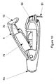
- Figures 9 to 11 illustrate an example in which the container 11 and chamber 12 together form a capsule 90 that can be inserted into a housing 2.
- the housing 2, including nozzle unit 42 and quill 44 are therefore reused with each of a plurality of refills that are sequentially inserted into the housing 2.
- the actuation mechanism is substantially the same as that for the dispenser 1 illustrated in Figures 1 to 4 in that when the cover 4 and the housing 2 are urged together, the cam 51 moves the capsule 90 along the guide rails 17 until the weakened wall of the container 11 comes into contact with the quill 44.
- a tab 91 is provided on the capsule 90 that protrudes beyond the housing 2 in the vicinity of the projection 10 at the back of the cover 4.
- the provision of this tab 91 impedes the movement of the capsule 90 into the housing 2 and thereby prevents inadvertent actuation of the dispenser 1.
- the tab 91 is shown most clearly in Figure 11 .
- the tab 91 extends from the face of the contained 11 that is adjacent to the projection 10 from the cover 4, in use.
- the tab 91 is elongate and has a frangible portion 92 which may consist of a narrowing or one or more perforations.
- the frangible portion 92 enables the tab 91 to be torn off when the dispenser 1 is prepared for use.
- the provision of the tab 91 ensures that the dispenser 1 cannot be accidentally actuated.
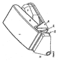
- Figure 12 shows an alternative capsule 120 that can be used in the dispenser 1 illustrated in Figures 1 to 4 or 9 to 11 .
- the capsule 120 has an extended base 121 and a cap 122.
- the shape of the base 121 closely conforms to the sidewalls and end portion of the container 11 furthest distant from the chamber 12.
- the base 121 then extends beyond the shoulder 123 of the container 11 up to a point parallel to the weakened end wall of the chamber 12.
- the cap 122 has an envelope that closely conforms to the outer profile of the container 11 and chamber 12.
- the provision of an extended base 121 makes the capsule 120 more robust as it is less Likely to flex at the point where the container 11 and the chamber 12 meet.
- the more robust form ensures, therefore, that the weakened end wall of the chamber is correctly positioned to be pierced by the quill 44 in use.
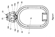
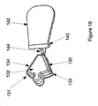
- Figures 13 to 16 illustrate a circular dispenser configured to dispense a plurality of doses.
- the dispenser takes the form of a pouch 130 that is configured to hold seven capsules or wedges 131 each of which comprises a container 11 and a chamber 12.
- Each wedge 131 has a substantially flat top 132 and a substantially flat base 133 and side walls 134, 135 that extend orthogonally between the top 132 and the base 133.
- Each wedge 131 is an equal segment of a circle which is truncated in order to provide a small central area 136 about which the wedges 131 are mounted to enable them to be rotated within the pouch 130.
- the pouch 130 takes the form of a slim circular disc comprising a circular base 138, a circular top 139 and an annular side wall 140. Part of the side wall is cut away so that the outer wall of the chamber of one of the wedges 131 is available to the user through the gap 141 in the pouch. The user can therefore rotate the wedges 131 using a cam system (not shown) so that a different wedge 131 is adjacent the nozzle unit 42.
- the circular top 139 is provided with a flap 142.
- the flap 142 is pivotably mounted on the circular top 139 so that it can move between a position substantially flush with the circular top 139 and a position in which the part of the flap furthest distant from the pivot protrudes above the circular top 139.
- the flap 142 is provided, at a position beyond the pivot point 143, with a hook 144.
- the hook 144 is configured to bear against the wedge 131 that is aligned for actuation. When the flap 142 is pivoted so that it becomes flush with the circular top 139, the hook 144 urges the wedge 131 into position for actuation.
- wedges 131 There are seven wedges 131, one for use on each day of the week. However, for different dosage regimens, different numbers of wedges 131 could be used, for example 3, 4, 5, 6, 8, 9 or 10 wedges 131.
- the wedges are mounted on a carousel which is rotated on guide rails that interface with the side walls of one of the wedges to ensure that wedge is correctly positioned for actuation.
- the wedges are mounted on a carousel which is a circular platen with radial ridges between which the wedges can be secured. The ridges may extend over part or substantially all of the radius of the carousel, but do not extend into the central area.
- the carousel is rotatably mounted on the base of the pouch so that it can rotate relative to the pouch.
- the provision of a number of wedges within a single pouch does not increase the overall size of the pouch considerably in comparison with a system with a single container because only one nozzle unit, one quill and one actuation mechanism is required.
- the pouch has a diameter in the region of 50mm to 100mm, preferably 60mm and each of the wedges can contain a payload of 1 to 30mg including medicament together with suitable excipients.
- dispensers 1 shown in the accompanying drawings have a single nozzle unit with a single central duct
- a further example is envisaged that comprises two of any one of the illustrated examples, formed back to back to provide two nozzle unit spaced apart such that each nozzle can discharge medicament into one nostril.
- the provision of a pair of dispensers in a back to back configuration enables actuation of the two devices simultaneously by compressing the two covers towards one another by pinching them between finger and thumb, for example. In this way, medicament can be simultaneously dispensed into both nostrils by a single actuation action.
- the two dispensers could be prepared separately and then joined, or alternatively they may be formed together with a common base.
Landscapes
- Health & Medical Sciences (AREA)
- Engineering & Computer Science (AREA)
- Life Sciences & Earth Sciences (AREA)
- Veterinary Medicine (AREA)
- Public Health (AREA)
- General Health & Medical Sciences (AREA)
- Animal Behavior & Ethology (AREA)
- Pulmonology (AREA)
- Hematology (AREA)
- Heart & Thoracic Surgery (AREA)
- Biomedical Technology (AREA)
- Anesthesiology (AREA)
- Bioinformatics & Cheminformatics (AREA)
- Pharmacology & Pharmacy (AREA)
- Containers And Packaging Bodies Having A Special Means To Remove Contents (AREA)
Claims (13)
- Capsule (90) destinée à servir dans un distributeur (1) de médicament, la capsule (90) comprenantun réservoir (11) pour un fluide,une chambre (12) destinée à contenir des particules, etune paire de canaux (13a, 13b) qui passent entre le réservoir (11) et la chambre (12) pour permettre une communication de fluide entre le réservoir (11) et la chambre (12) à l'utilisation etcaractérisé par le fait qu'il est prévu au moins deux surfaces concaves (32a, 32b) dans la chambre (12), qui sont conçues pour impartir un mouvement de rotation au fluide et/ou aux particules de fluide qui empiètent sur celles-ci et/ou coulent le long de celles-ci depuis au moins une paire de canaux (13a, 13b) passant entre le réservoir (11) et la chambre (12), dans laquelle capsule le réservoir (11) est pressurisé.
- Capsule (90) selon la revendication 1, dans laquelle la chambre (12) est conçue pour amener le fluide à rentrer avec les particules dans la chambre (12) pour le désagréger ou l'agiter en un flux turbulent afin de produire un fluide mobile contenant les particules.
- Capsule (90) selon la revendication 2, dans laquelle le flux turbulent est un flux cyclonique ou vortical.
- Capsule (90) selon l'une quelconque des revendications 1 à 3, dans laquelle le fluide contenu dans le réservoir (11) est pressurisé.
- Capsule (90) selon l'une quelconque des revendications précédentes, comportant au moins un canal coopérant avec au moins une paroi de la chambre (12).
- Capsule (90) selon l'une quelconque des revendications précédentes, dans laquelle la chambre (12) comprend deux parties sensiblement cylindriques et dans laquelle chacun des canaux (13a, 13b) fait rentrer du fluide tangentiellement dans une partie cylindrique respective.
- Capsule (90) selon l'une quelconque des revendications précédentes, comprenant en outre des moyens de distribution (51) qui sont irréversibles et sont montés sur ou font partie intégrante ou sont en communication avec les canaux (13a, 13b).
- Distributeur (1) comprenant une capsule (90) selon la revendication 1.
- Distributeur (1) selon la revendication 8, comprenant en outre une sortie de décharge apte à être mise en communication de fluide avec la chambre (12).
- Distributeur (1) selon la revendication 8 ou la revendication 9, comprenant en outre un fourreau creux (44) pour percer la paroi de la chambre (12) afin de permettre au fluide mobile de sortir de la capsule (90) et du distributeur (1).
- Distributeur (1) comprenant une capsule selon la revendication 1, dans lequel la capsule (90) est partie intégrante du distributeur (1).
- Distributeur (1) selon l'une quelconque des revendications 8 à 11, dans lequel le distributeur (1) est conçu pour loger plus d'une capsule (90).
- Distributeur (1) selon la revendication 12, dans lequel une pluralité de capsules (90) sont disposées en réseau circulaire et dans lequel chaque capsule est réalisée en forme de segment circulaire.
Applications Claiming Priority (2)
| Application Number | Priority Date | Filing Date | Title |
|---|---|---|---|
| GB0806735.7A GB2459257B (en) | 2008-04-14 | 2008-04-14 | Particulate dispenser |
| PCT/GB2009/050359 WO2009127860A1 (fr) | 2008-04-14 | 2009-04-14 | Dispositif de distribution de particules |
Publications (2)
| Publication Number | Publication Date |
|---|---|
| EP2271388A1 EP2271388A1 (fr) | 2011-01-12 |
| EP2271388B1 true EP2271388B1 (fr) | 2015-11-11 |
Family
ID=39433603
Family Applications (1)
| Application Number | Title | Priority Date | Filing Date |
|---|---|---|---|
| EP09732550.0A Active EP2271388B1 (fr) | 2008-04-14 | 2009-04-14 | Dispositif de distribution de particules |
Country Status (5)
| Country | Link |
|---|---|
| US (1) | US8695592B2 (fr) |
| EP (1) | EP2271388B1 (fr) |
| ES (1) | ES2562223T3 (fr) |
| GB (1) | GB2459257B (fr) |
| WO (1) | WO2009127860A1 (fr) |
Cited By (1)
| Publication number | Priority date | Publication date | Assignee | Title |
|---|---|---|---|---|
| WO2023094821A1 (fr) | 2021-11-25 | 2023-06-01 | Alchemy Pharmatech Limited | Dispositif d'administration de médicaments amélioré |
Families Citing this family (6)
| Publication number | Priority date | Publication date | Assignee | Title |
|---|---|---|---|---|
| AU2008229566A1 (en) * | 2007-03-22 | 2008-09-25 | Felix Wirz | Method and device for generating mechanical energy |
| US8393357B2 (en) * | 2009-07-08 | 2013-03-12 | Medtronic Minimed, Inc. | Reservoir filling systems and methods |
| US8167846B2 (en) | 2009-07-08 | 2012-05-01 | Medtronic Minimed, Inc. | Reservoir filling systems and methods |
| US10874139B2 (en) * | 2015-07-07 | 2020-12-29 | Altria Client Services Llc | E-vapor device including capsule containing pre-vapor formulation |
| FR3046552B1 (fr) | 2016-01-07 | 2018-02-16 | Aptar France Sas | Dispositif de distribution nasale de poudre. |
| US10238577B2 (en) * | 2016-07-25 | 2019-03-26 | Zeteo Biomedical LLC | Oral delivery device and methods |
Citations (1)
| Publication number | Priority date | Publication date | Assignee | Title |
|---|---|---|---|---|
| EP1488819A1 (fr) * | 2003-06-16 | 2004-12-22 | Rijksuniversiteit te Groningen | Inhalateur de poudre sèche et procédé d'inhalation pulmonaire de poudre sèche |
Family Cites Families (17)
| Publication number | Priority date | Publication date | Assignee | Title |
|---|---|---|---|---|
| US3653380A (en) * | 1970-02-16 | 1972-04-04 | American Cyanamid Co | Aerosol powder dosage dispensing device |
| US4599082A (en) * | 1984-08-13 | 1986-07-08 | Becton, Dickinson And Company | Two-component syringe assembly |
| US5215221A (en) * | 1992-05-07 | 1993-06-01 | The Procter & Gamble Company | Disposable unit dose dispenser for powdered medicants |
| US6062213A (en) * | 1998-06-16 | 2000-05-16 | Fuisz Technologies Ltd. | Single unit dose inhalation therapy device |
| EP1757321A3 (fr) * | 1999-07-12 | 2007-11-28 | Capnia Incorporated | Procédés et dispositif pour soulager les céphalées, les rhinites et d'autres affections communes |
| US6427688B1 (en) * | 2000-02-01 | 2002-08-06 | Dura Pharmaceuticals, Icn. | Dry powder inhaler |
| US6443152B1 (en) * | 2001-01-12 | 2002-09-03 | Becton Dickinson And Company | Medicament respiratory delivery device |
| GB2380410B (en) * | 2001-10-05 | 2003-11-19 | Alchemy Healthcare Ltd | Apparatus for the nasal or oral delivery of a medicament |
| GB0215904D0 (en) * | 2002-07-09 | 2002-08-21 | Team Holdings Uk Ltd | Drug delivery system and method |
| JP2006507876A (ja) * | 2002-12-02 | 2006-03-09 | ザ・ガバナーズ・オブ・ザ・ユニバーシティ・オブ・アルバータ | 吸入用粉末の解凝集のための装置及び方法 |
| GB2405798A (en) * | 2003-09-15 | 2005-03-16 | Vectura Ltd | Dry powder inhaler with primary and secondary piercing elements and a medicament pack for use with an inhalation device. |
| US7861712B2 (en) * | 2004-04-23 | 2011-01-04 | Manta Product Development | Sealed capsule including an integrated puncturing mechanism |
| US8763605B2 (en) * | 2005-07-20 | 2014-07-01 | Manta Devices, Llc | Inhalation device |
| EP1795221A1 (fr) * | 2005-12-02 | 2007-06-13 | Boehringer Ingelheim Pharma GmbH & Co. KG | Appareil pour distribuer, stocker, et méthode pour distribuer une formulation |
| US7841338B2 (en) * | 2006-04-13 | 2010-11-30 | Boehringer Ingelheim International Gmbh | Dispensing device |
| GB0623728D0 (en) * | 2006-11-28 | 2007-01-10 | Optinose As | Delivery devices |
| EP2164799B1 (fr) * | 2007-05-16 | 2018-12-26 | Mystic Pharmaceuticals, Inc. | Conteneurs de distribution de doses à unité de combinaison |
-
2008
- 2008-04-14 GB GB0806735.7A patent/GB2459257B/en active Active
-
2009
- 2009-04-14 ES ES09732550.0T patent/ES2562223T3/es active Active
- 2009-04-14 US US12/736,507 patent/US8695592B2/en active Active
- 2009-04-14 EP EP09732550.0A patent/EP2271388B1/fr active Active
- 2009-04-14 WO PCT/GB2009/050359 patent/WO2009127860A1/fr active Application Filing
Patent Citations (1)
| Publication number | Priority date | Publication date | Assignee | Title |
|---|---|---|---|---|
| EP1488819A1 (fr) * | 2003-06-16 | 2004-12-22 | Rijksuniversiteit te Groningen | Inhalateur de poudre sèche et procédé d'inhalation pulmonaire de poudre sèche |
Cited By (1)
| Publication number | Priority date | Publication date | Assignee | Title |
|---|---|---|---|---|
| WO2023094821A1 (fr) | 2021-11-25 | 2023-06-01 | Alchemy Pharmatech Limited | Dispositif d'administration de médicaments amélioré |
Also Published As
| Publication number | Publication date |
|---|---|
| WO2009127860A1 (fr) | 2009-10-22 |
| GB2459257B (en) | 2012-12-19 |
| US8695592B2 (en) | 2014-04-15 |
| ES2562223T3 (es) | 2016-03-03 |
| EP2271388A1 (fr) | 2011-01-12 |
| GB2459257A (en) | 2009-10-21 |
| GB0806735D0 (en) | 2008-05-14 |
| US20110114671A1 (en) | 2011-05-19 |
Similar Documents
| Publication | Publication Date | Title |
|---|---|---|
| EP2271388B1 (fr) | Dispositif de distribution de particules | |
| AU683905B2 (en) | Device for administering pharmaceutical substances | |
| US6484715B1 (en) | Media dispenser | |
| JP4680463B2 (ja) | 薬剤を鼻腔に供給する装置及び方法 | |
| ES2596263T3 (es) | Aparato de dispersión de polvo | |
| JP4601627B2 (ja) | 舌下薬物送達デバイス | |
| CA2652283C (fr) | Inhalateur de poudre seche pour usage pulmonaire ou nasal | |
| ES2384648T3 (es) | Inhalador para sustancias en polvo | |
| US7832399B2 (en) | Medication inhaler | |
| EA007403B1 (ru) | Устройство для выдачи жидкостей, используемый в нём сменный баллончик и система, состоящая из устройства для выдачи жидкостей и сменного баллончика | |
| HU220472B1 (hu) | Eljárás és készülék por aeroszolosítására, valamint a készülékben alkalmazott adagolócső-egység | |
| JP2010515541A (ja) | 経鼻カートリッジデバイス | |
| US20040149283A1 (en) | Powder inhaler comprising a chamber for a capsule for taking up a non-returnable capsule being filled with an active ingredient | |
| US20170106154A1 (en) | Dry powder inhaler | |
| EP3682922B1 (fr) | Cartouche de stockage de médicament dotée d'une buse, pulvérisateur associé, et dispositif de distribution de médicament en poudre pour cavité nasale | |
| JP2013524976A (ja) | 簡易なカプセル・ベースの吸入器 | |
| EA009854B1 (ru) | Распылитель жидкостей медицинского назначения | |
| RU2669930C2 (ru) | Дозирование жидкостей и способы дозирования жидкостей | |
| JPH0670980A (ja) | ディスペンサー | |
| JP2004506495A (ja) | スプレー装置 | |
| EP2670462A1 (fr) | Dispositifs d'administration intranasale | |
| US20210213262A1 (en) | Device for delivering medication | |
| US20180344950A1 (en) | Triggered quantal drug delivery device, method and system ("tqd3") | |
| EP3362183B1 (fr) | Dispositif de distribution de médicament | |
| WO2024165494A1 (fr) | Dispositif d'écoulement à pointe de perforation améliorée |
Legal Events
| Date | Code | Title | Description |
|---|---|---|---|
| PUAI | Public reference made under article 153(3) epc to a published international application that has entered the european phase |
Free format text: ORIGINAL CODE: 0009012 |
|
| 17P | Request for examination filed |
Effective date: 20101112 |
|
| AK | Designated contracting states |
Kind code of ref document: A1 Designated state(s): AT BE BG CH CY CZ DE DK EE ES FI FR GB GR HR HU IE IS IT LI LT LU LV MC MK MT NL NO PL PT RO SE SI SK TR |
|
| AX | Request for extension of the european patent |
Extension state: AL BA RS |
|
| DAX | Request for extension of the european patent (deleted) | ||
| 17Q | First examination report despatched |
Effective date: 20140602 |
|
| GRAP | Despatch of communication of intention to grant a patent |
Free format text: ORIGINAL CODE: EPIDOSNIGR1 |
|
| INTG | Intention to grant announced |
Effective date: 20150602 |
|
| GRAS | Grant fee paid |
Free format text: ORIGINAL CODE: EPIDOSNIGR3 |
|
| GRAA | (expected) grant |
Free format text: ORIGINAL CODE: 0009210 |
|
| AK | Designated contracting states |
Kind code of ref document: B1 Designated state(s): AT BE BG CH CY CZ DE DK EE ES FI FR GB GR HR HU IE IS IT LI LT LU LV MC MK MT NL NO PL PT RO SE SI SK TR |
|
| REG | Reference to a national code |
Ref country code: GB Ref legal event code: FG4D |
|
| REG | Reference to a national code |
Ref country code: CH Ref legal event code: EP |
|
| REG | Reference to a national code |
Ref country code: IE Ref legal event code: FG4D |
|
| REG | Reference to a national code |
Ref country code: AT Ref legal event code: REF Ref document number: 760143 Country of ref document: AT Kind code of ref document: T Effective date: 20151215 |
|
| REG | Reference to a national code |
Ref country code: DE Ref legal event code: R096 Ref document number: 602009034791 Country of ref document: DE |
|
| REG | Reference to a national code |
Ref country code: ES Ref legal event code: FG2A Ref document number: 2562223 Country of ref document: ES Kind code of ref document: T3 Effective date: 20160303 |
|
| REG | Reference to a national code |
Ref country code: LT Ref legal event code: MG4D |
|
| REG | Reference to a national code |
Ref country code: NL Ref legal event code: MP Effective date: 20160211 |
|
| REG | Reference to a national code |
Ref country code: AT Ref legal event code: MK05 Ref document number: 760143 Country of ref document: AT Kind code of ref document: T Effective date: 20151111 |
|
| REG | Reference to a national code |
Ref country code: FR Ref legal event code: PLFP Year of fee payment: 8 |
|
| PG25 | Lapsed in a contracting state [announced via postgrant information from national office to epo] |
Ref country code: HR Free format text: LAPSE BECAUSE OF FAILURE TO SUBMIT A TRANSLATION OF THE DESCRIPTION OR TO PAY THE FEE WITHIN THE PRESCRIBED TIME-LIMIT Effective date: 20151111 Ref country code: NL Free format text: LAPSE BECAUSE OF FAILURE TO SUBMIT A TRANSLATION OF THE DESCRIPTION OR TO PAY THE FEE WITHIN THE PRESCRIBED TIME-LIMIT Effective date: 20151111 Ref country code: IS Free format text: LAPSE BECAUSE OF FAILURE TO SUBMIT A TRANSLATION OF THE DESCRIPTION OR TO PAY THE FEE WITHIN THE PRESCRIBED TIME-LIMIT Effective date: 20160311 Ref country code: NO Free format text: LAPSE BECAUSE OF FAILURE TO SUBMIT A TRANSLATION OF THE DESCRIPTION OR TO PAY THE FEE WITHIN THE PRESCRIBED TIME-LIMIT Effective date: 20160211 Ref country code: LT Free format text: LAPSE BECAUSE OF FAILURE TO SUBMIT A TRANSLATION OF THE DESCRIPTION OR TO PAY THE FEE WITHIN THE PRESCRIBED TIME-LIMIT Effective date: 20151111 |
|
| REG | Reference to a national code |
Ref country code: DE Ref legal event code: R082 Ref document number: 602009034791 Country of ref document: DE Representative=s name: HERNANDEZ, YORCK, DIPL.-ING., DE |
|
| PG25 | Lapsed in a contracting state [announced via postgrant information from national office to epo] |
Ref country code: LV Free format text: LAPSE BECAUSE OF FAILURE TO SUBMIT A TRANSLATION OF THE DESCRIPTION OR TO PAY THE FEE WITHIN THE PRESCRIBED TIME-LIMIT Effective date: 20151111 Ref country code: SE Free format text: LAPSE BECAUSE OF FAILURE TO SUBMIT A TRANSLATION OF THE DESCRIPTION OR TO PAY THE FEE WITHIN THE PRESCRIBED TIME-LIMIT Effective date: 20151111 Ref country code: PL Free format text: LAPSE BECAUSE OF FAILURE TO SUBMIT A TRANSLATION OF THE DESCRIPTION OR TO PAY THE FEE WITHIN THE PRESCRIBED TIME-LIMIT Effective date: 20151111 Ref country code: AT Free format text: LAPSE BECAUSE OF FAILURE TO SUBMIT A TRANSLATION OF THE DESCRIPTION OR TO PAY THE FEE WITHIN THE PRESCRIBED TIME-LIMIT Effective date: 20151111 Ref country code: FI Free format text: LAPSE BECAUSE OF FAILURE TO SUBMIT A TRANSLATION OF THE DESCRIPTION OR TO PAY THE FEE WITHIN THE PRESCRIBED TIME-LIMIT Effective date: 20151111 Ref country code: GR Free format text: LAPSE BECAUSE OF FAILURE TO SUBMIT A TRANSLATION OF THE DESCRIPTION OR TO PAY THE FEE WITHIN THE PRESCRIBED TIME-LIMIT Effective date: 20160212 Ref country code: PT Free format text: LAPSE BECAUSE OF FAILURE TO SUBMIT A TRANSLATION OF THE DESCRIPTION OR TO PAY THE FEE WITHIN THE PRESCRIBED TIME-LIMIT Effective date: 20160311 |
|
| PG25 | Lapsed in a contracting state [announced via postgrant information from national office to epo] |
Ref country code: CZ Free format text: LAPSE BECAUSE OF FAILURE TO SUBMIT A TRANSLATION OF THE DESCRIPTION OR TO PAY THE FEE WITHIN THE PRESCRIBED TIME-LIMIT Effective date: 20151111 |
|
| REG | Reference to a national code |
Ref country code: DE Ref legal event code: R097 Ref document number: 602009034791 Country of ref document: DE |
|
| REG | Reference to a national code |
Ref country code: DE Ref legal event code: R082 Ref document number: 602009034791 Country of ref document: DE Representative=s name: HERNANDEZ, YORCK, DIPL.-ING., DE Ref country code: DE Ref legal event code: R081 Ref document number: 602009034791 Country of ref document: DE Owner name: ALCHEMY PHARMATECH LTD., GB Free format text: FORMER OWNER: ALCHEMY HEALTHCARE LTD., OXFORD, GB |
|
| PG25 | Lapsed in a contracting state [announced via postgrant information from national office to epo] |
Ref country code: SK Free format text: LAPSE BECAUSE OF FAILURE TO SUBMIT A TRANSLATION OF THE DESCRIPTION OR TO PAY THE FEE WITHIN THE PRESCRIBED TIME-LIMIT Effective date: 20151111 Ref country code: DK Free format text: LAPSE BECAUSE OF FAILURE TO SUBMIT A TRANSLATION OF THE DESCRIPTION OR TO PAY THE FEE WITHIN THE PRESCRIBED TIME-LIMIT Effective date: 20151111 Ref country code: BE Free format text: LAPSE BECAUSE OF NON-PAYMENT OF DUE FEES Effective date: 20160430 Ref country code: RO Free format text: LAPSE BECAUSE OF FAILURE TO SUBMIT A TRANSLATION OF THE DESCRIPTION OR TO PAY THE FEE WITHIN THE PRESCRIBED TIME-LIMIT Effective date: 20151111 Ref country code: EE Free format text: LAPSE BECAUSE OF FAILURE TO SUBMIT A TRANSLATION OF THE DESCRIPTION OR TO PAY THE FEE WITHIN THE PRESCRIBED TIME-LIMIT Effective date: 20151111 |
|
| PLBE | No opposition filed within time limit |
Free format text: ORIGINAL CODE: 0009261 |
|
| STAA | Information on the status of an ep patent application or granted ep patent |
Free format text: STATUS: NO OPPOSITION FILED WITHIN TIME LIMIT |
|
| REG | Reference to a national code |
Ref country code: FR Ref legal event code: TP Owner name: ALCHEMY PHARMATEC LIMITED, GB Effective date: 20160826 |
|
| 26N | No opposition filed |
Effective date: 20160812 |
|
| REG | Reference to a national code |
Ref country code: ES Ref legal event code: PC2A Owner name: ALCHEMY PHARMATECH LIMITED Effective date: 20161028 |
|
| PG25 | Lapsed in a contracting state [announced via postgrant information from national office to epo] |
Ref country code: SI Free format text: LAPSE BECAUSE OF FAILURE TO SUBMIT A TRANSLATION OF THE DESCRIPTION OR TO PAY THE FEE WITHIN THE PRESCRIBED TIME-LIMIT Effective date: 20151111 |
|
| REG | Reference to a national code |
Ref country code: CH Ref legal event code: PL |
|
| REG | Reference to a national code |
Ref country code: GB Ref legal event code: 732E Free format text: REGISTERED BETWEEN 20161117 AND 20161123 |
|
| PG25 | Lapsed in a contracting state [announced via postgrant information from national office to epo] |
Ref country code: BE Free format text: LAPSE BECAUSE OF FAILURE TO SUBMIT A TRANSLATION OF THE DESCRIPTION OR TO PAY THE FEE WITHIN THE PRESCRIBED TIME-LIMIT Effective date: 20151111 Ref country code: LU Free format text: LAPSE BECAUSE OF FAILURE TO SUBMIT A TRANSLATION OF THE DESCRIPTION OR TO PAY THE FEE WITHIN THE PRESCRIBED TIME-LIMIT Effective date: 20160414 |
|
| REG | Reference to a national code |
Ref country code: IE Ref legal event code: MM4A |
|
| PG25 | Lapsed in a contracting state [announced via postgrant information from national office to epo] |
Ref country code: CH Free format text: LAPSE BECAUSE OF NON-PAYMENT OF DUE FEES Effective date: 20160430 Ref country code: LI Free format text: LAPSE BECAUSE OF NON-PAYMENT OF DUE FEES Effective date: 20160430 |
|
| REG | Reference to a national code |
Ref country code: FR Ref legal event code: PLFP Year of fee payment: 9 |
|
| PG25 | Lapsed in a contracting state [announced via postgrant information from national office to epo] |
Ref country code: IE Free format text: LAPSE BECAUSE OF NON-PAYMENT OF DUE FEES Effective date: 20160414 |
|
| REG | Reference to a national code |
Ref country code: FR Ref legal event code: PLFP Year of fee payment: 10 |
|
| PG25 | Lapsed in a contracting state [announced via postgrant information from national office to epo] |
Ref country code: CY Free format text: LAPSE BECAUSE OF FAILURE TO SUBMIT A TRANSLATION OF THE DESCRIPTION OR TO PAY THE FEE WITHIN THE PRESCRIBED TIME-LIMIT Effective date: 20151111 Ref country code: HU Free format text: LAPSE BECAUSE OF FAILURE TO SUBMIT A TRANSLATION OF THE DESCRIPTION OR TO PAY THE FEE WITHIN THE PRESCRIBED TIME-LIMIT; INVALID AB INITIO Effective date: 20090414 |
|
| PG25 | Lapsed in a contracting state [announced via postgrant information from national office to epo] |
Ref country code: MK Free format text: LAPSE BECAUSE OF FAILURE TO SUBMIT A TRANSLATION OF THE DESCRIPTION OR TO PAY THE FEE WITHIN THE PRESCRIBED TIME-LIMIT Effective date: 20151111 Ref country code: TR Free format text: LAPSE BECAUSE OF FAILURE TO SUBMIT A TRANSLATION OF THE DESCRIPTION OR TO PAY THE FEE WITHIN THE PRESCRIBED TIME-LIMIT Effective date: 20151111 Ref country code: MC Free format text: LAPSE BECAUSE OF FAILURE TO SUBMIT A TRANSLATION OF THE DESCRIPTION OR TO PAY THE FEE WITHIN THE PRESCRIBED TIME-LIMIT Effective date: 20151111 Ref country code: MT Free format text: LAPSE BECAUSE OF NON-PAYMENT OF DUE FEES Effective date: 20160430 |
|
| PG25 | Lapsed in a contracting state [announced via postgrant information from national office to epo] |
Ref country code: BG Free format text: LAPSE BECAUSE OF FAILURE TO SUBMIT A TRANSLATION OF THE DESCRIPTION OR TO PAY THE FEE WITHIN THE PRESCRIBED TIME-LIMIT Effective date: 20151111 |
|
| PGFP | Annual fee paid to national office [announced via postgrant information from national office to epo] |
Ref country code: GB Payment date: 20240418 Year of fee payment: 16 |
|
| PGFP | Annual fee paid to national office [announced via postgrant information from national office to epo] |
Ref country code: DE Payment date: 20240418 Year of fee payment: 16 |
|
| PGFP | Annual fee paid to national office [announced via postgrant information from national office to epo] |
Ref country code: ES Payment date: 20240524 Year of fee payment: 16 |
|
| PGFP | Annual fee paid to national office [announced via postgrant information from national office to epo] |
Ref country code: IT Payment date: 20240419 Year of fee payment: 16 Ref country code: FR Payment date: 20240426 Year of fee payment: 16 |