EP2270943A2 - Procédé de fixation d'un élément de fixation ainsi qu'élément de fixation pour un élément de type tubulaire - Google Patents
Procédé de fixation d'un élément de fixation ainsi qu'élément de fixation pour un élément de type tubulaire Download PDFInfo
- Publication number
- EP2270943A2 EP2270943A2 EP10450108A EP10450108A EP2270943A2 EP 2270943 A2 EP2270943 A2 EP 2270943A2 EP 10450108 A EP10450108 A EP 10450108A EP 10450108 A EP10450108 A EP 10450108A EP 2270943 A2 EP2270943 A2 EP 2270943A2
- Authority
- EP
- European Patent Office
- Prior art keywords
- fastening element
- opening
- foot
- intermediate piece
- receptacle
- Prior art date
- Legal status (The legal status is an assumption and is not a legal conclusion. Google has not performed a legal analysis and makes no representation as to the accuracy of the status listed.)
- Withdrawn
Links
- 238000000034 method Methods 0.000 title claims abstract description 13
- 229920003023 plastic Polymers 0.000 claims description 6
- 239000004033 plastic Substances 0.000 claims description 6
- 239000000463 material Substances 0.000 claims description 5
- 230000000295 complement effect Effects 0.000 claims description 2
- 238000003780 insertion Methods 0.000 claims description 2
- 230000037431 insertion Effects 0.000 claims description 2
- 125000006850 spacer group Chemical group 0.000 description 9
- 101100327917 Caenorhabditis elegans chup-1 gene Proteins 0.000 description 4
- 238000004519 manufacturing process Methods 0.000 description 3
- 230000008878 coupling Effects 0.000 description 2
- 238000010168 coupling process Methods 0.000 description 2
- 238000005859 coupling reaction Methods 0.000 description 2
- 238000006073 displacement reaction Methods 0.000 description 2
- 238000009420 retrofitting Methods 0.000 description 2
- 230000006978 adaptation Effects 0.000 description 1
- 238000004873 anchoring Methods 0.000 description 1
- 230000015572 biosynthetic process Effects 0.000 description 1
- 238000005253 cladding Methods 0.000 description 1
- 230000002153 concerted effect Effects 0.000 description 1
- 230000002349 favourable effect Effects 0.000 description 1
- 230000000284 resting effect Effects 0.000 description 1
Images


Classifications
-
- F—MECHANICAL ENGINEERING; LIGHTING; HEATING; WEAPONS; BLASTING
- F16—ENGINEERING ELEMENTS AND UNITS; GENERAL MEASURES FOR PRODUCING AND MAINTAINING EFFECTIVE FUNCTIONING OF MACHINES OR INSTALLATIONS; THERMAL INSULATION IN GENERAL
- F16L—PIPES; JOINTS OR FITTINGS FOR PIPES; SUPPORTS FOR PIPES, CABLES OR PROTECTIVE TUBING; MEANS FOR THERMAL INSULATION IN GENERAL
- F16L3/00—Supports for pipes, cables or protective tubing, e.g. hangers, holders, clamps, cleats, clips, brackets
- F16L3/08—Supports for pipes, cables or protective tubing, e.g. hangers, holders, clamps, cleats, clips, brackets substantially surrounding the pipe, cable or protective tubing
- F16L3/12—Supports for pipes, cables or protective tubing, e.g. hangers, holders, clamps, cleats, clips, brackets substantially surrounding the pipe, cable or protective tubing comprising a member substantially surrounding the pipe, cable or protective tubing
- F16L3/13—Supports for pipes, cables or protective tubing, e.g. hangers, holders, clamps, cleats, clips, brackets substantially surrounding the pipe, cable or protective tubing comprising a member substantially surrounding the pipe, cable or protective tubing and engaging it by snap action
-
- F—MECHANICAL ENGINEERING; LIGHTING; HEATING; WEAPONS; BLASTING
- F16—ENGINEERING ELEMENTS AND UNITS; GENERAL MEASURES FOR PRODUCING AND MAINTAINING EFFECTIVE FUNCTIONING OF MACHINES OR INSTALLATIONS; THERMAL INSULATION IN GENERAL
- F16L—PIPES; JOINTS OR FITTINGS FOR PIPES; SUPPORTS FOR PIPES, CABLES OR PROTECTIVE TUBING; MEANS FOR THERMAL INSULATION IN GENERAL
- F16L3/00—Supports for pipes, cables or protective tubing, e.g. hangers, holders, clamps, cleats, clips, brackets
- F16L3/08—Supports for pipes, cables or protective tubing, e.g. hangers, holders, clamps, cleats, clips, brackets substantially surrounding the pipe, cable or protective tubing
- F16L3/12—Supports for pipes, cables or protective tubing, e.g. hangers, holders, clamps, cleats, clips, brackets substantially surrounding the pipe, cable or protective tubing comprising a member substantially surrounding the pipe, cable or protective tubing
-
- F—MECHANICAL ENGINEERING; LIGHTING; HEATING; WEAPONS; BLASTING
- F16—ENGINEERING ELEMENTS AND UNITS; GENERAL MEASURES FOR PRODUCING AND MAINTAINING EFFECTIVE FUNCTIONING OF MACHINES OR INSTALLATIONS; THERMAL INSULATION IN GENERAL
- F16L—PIPES; JOINTS OR FITTINGS FOR PIPES; SUPPORTS FOR PIPES, CABLES OR PROTECTIVE TUBING; MEANS FOR THERMAL INSULATION IN GENERAL
- F16L3/00—Supports for pipes, cables or protective tubing, e.g. hangers, holders, clamps, cleats, clips, brackets
- F16L3/22—Supports for pipes, cables or protective tubing, e.g. hangers, holders, clamps, cleats, clips, brackets specially adapted for supporting a number of parallel pipes at intervals
- F16L3/237—Supports for pipes, cables or protective tubing, e.g. hangers, holders, clamps, cleats, clips, brackets specially adapted for supporting a number of parallel pipes at intervals for two pipes
-
- F—MECHANICAL ENGINEERING; LIGHTING; HEATING; WEAPONS; BLASTING
- F16—ENGINEERING ELEMENTS AND UNITS; GENERAL MEASURES FOR PRODUCING AND MAINTAINING EFFECTIVE FUNCTIONING OF MACHINES OR INSTALLATIONS; THERMAL INSULATION IN GENERAL
- F16L—PIPES; JOINTS OR FITTINGS FOR PIPES; SUPPORTS FOR PIPES, CABLES OR PROTECTIVE TUBING; MEANS FOR THERMAL INSULATION IN GENERAL
- F16L3/00—Supports for pipes, cables or protective tubing, e.g. hangers, holders, clamps, cleats, clips, brackets
- F16L3/24—Supports for pipes, cables or protective tubing, e.g. hangers, holders, clamps, cleats, clips, brackets with special member for attachment to profiled girders
- F16L3/243—Supports for pipes, cables or protective tubing, e.g. hangers, holders, clamps, cleats, clips, brackets with special member for attachment to profiled girders the special member being inserted in the profiled girder
- F16L3/2431—Supports for pipes, cables or protective tubing, e.g. hangers, holders, clamps, cleats, clips, brackets with special member for attachment to profiled girders the special member being inserted in the profiled girder the special member being inserted and subsequently rotated to a limited extent
-
- H—ELECTRICITY
- H02—GENERATION; CONVERSION OR DISTRIBUTION OF ELECTRIC POWER
- H02G—INSTALLATION OF ELECTRIC CABLES OR LINES, OR OF COMBINED OPTICAL AND ELECTRIC CABLES OR LINES
- H02G3/00—Installations of electric cables or lines or protective tubing therefor in or on buildings, equivalent structures or vehicles
- H02G3/30—Installations of cables or lines on walls, floors or ceilings
- H02G3/32—Installations of cables or lines on walls, floors or ceilings using mounting clamps
-
- F—MECHANICAL ENGINEERING; LIGHTING; HEATING; WEAPONS; BLASTING
- F16—ENGINEERING ELEMENTS AND UNITS; GENERAL MEASURES FOR PRODUCING AND MAINTAINING EFFECTIVE FUNCTIONING OF MACHINES OR INSTALLATIONS; THERMAL INSULATION IN GENERAL
- F16B—DEVICES FOR FASTENING OR SECURING CONSTRUCTIONAL ELEMENTS OR MACHINE PARTS TOGETHER, e.g. NAILS, BOLTS, CIRCLIPS, CLAMPS, CLIPS OR WEDGES; JOINTS OR JOINTING
- F16B21/00—Means for preventing relative axial movement of a pin, spigot, shaft or the like and a member surrounding it; Stud-and-socket releasable fastenings
- F16B21/02—Releasable fastening devices locking by rotation
-
- H—ELECTRICITY
- H02—GENERATION; CONVERSION OR DISTRIBUTION OF ELECTRIC POWER
- H02G—INSTALLATION OF ELECTRIC CABLES OR LINES, OR OF COMBINED OPTICAL AND ELECTRIC CABLES OR LINES
- H02G3/00—Installations of electric cables or lines or protective tubing therefor in or on buildings, equivalent structures or vehicles
- H02G3/02—Details
- H02G3/04—Protective tubing or conduits, e.g. cable ladders or cable troughs
- H02G3/0437—Channels
Definitions
- the present invention also relates to a fastener for a tubular element, in particular for a pipe, a conduit or the like., For fixing to a formed with at least one opening, in particular a slot recording, such as a cable cup, wherein the fastener or a so that couplable intermediate piece is provided with a foot element, which is a passage through the opening allows, wherein the one preferred longitudinal direction of extension comprising foot element on the fastening element or on a couplable with this intermediate piece spaced from a support surface of the fastener or spacer on the receptacle is formed and rotatable after passing through the opening for cooperation with edge or edge regions of the opening together with the fastener or spacer or is pivotable.
- a fastener for a tubular element in particular for a pipe, a conduit or the like.
- Such cable trays or generally perforated walls or similar devices which are used for example for cladding, usually have a plurality of holes or openings, in particular oblong holes, which extend for example in the longitudinal direction or normal of such receptacles, such as cable trays.
- a method and fastener of the type mentioned are, for example, the WO 2003/064867 , of the US 2003/0213876 or the US Pat. No. 6,209,827 refer to.
- a disadvantage of these known embodiments is their complicated structure and in particular the fact that use only with specially adapted to the training and contour of the foot element particular recordings is possible, so that for different shots each specially matched and not adjustable in the recording or adjustable Fasteners must be used.
- the present invention therefore aims to develop a method and a fastener of the type mentioned in that the above-mentioned problems of the prior art are avoided or at least reduced and that a rapid and secure fixing of such a fastener to one with at least one Opening provided or trained recording, in particular a cable cup is possible.
- the fasteners for receiving tubular elements, such as pipes or pipes, if possible known receiving elements or clamps, in particular a compatibility with known fasteners and a adjustability or displacement of the fasteners in the positioning or To provide arrangement.
- a method of the type mentioned is essentially characterized in that the fastening element or intermediate piece is arranged with the inserted foot element in the opening adjustable or displaceable.
- a fastener with a foot element which is a passage through the opening allows succeeds in a simple and rapid manner, an arrangement or definition of such a fastener on the recording, such as cable cup, which is formed with at least one opening.
- a usually plurality of spaced-apart fasteners can be moved to such a receptacle in a conventional manner, a pipe or a pipe, so that by simple means and in particular quick and easy Process steps in particular additional tubular elements or lines to an existing recording, such as a cable cup can be set.
- a further adjustability of a positioning or adjustability of the fixing element to be fixed to the receptacle is achieved according to the invention in that the fastening element or intermediate piece with the inserted foot element is arranged displaceably or displaceably in the opening.
- the fastening element or intermediate piece with the inserted foot element is arranged displaceably or displaceably in the opening.
- the twist angle for reaching over the edge or boundary areas of the opening by the foot member and to take a use position of the Fastening element with at least 20 °, preferably about 45 ° is selected. It is therefore sufficient according to the invention to achieve a secure fixing by a slight twisting or pivoting of the fastener or the intermediate piece with the foot element arranged thereon.
- the distance of the foot member is selected by a bearing surface of the fastener or spacer according to the thickness of the receptacle in the region of the opening.
- the fastener or the thus couplable intermediate piece is made with the foot element arranged thereon of a plastic material.
- a fastener of the above type is also characterized essentially characterized in that the fastener or spacer with the inserted foot element in the opening is arranged adjustable or displaceable.
- an easily fixable fastener for fixing or anchoring to an existing recording which is provided with at least one opening, in particular a slot, can be provided, so that in particular a retrofit of existing systems with tubular elements, For example, lines or the like.
- the adjustability or displaceability proposed according to the invention makes it possible to adjust the positioning according to possibly different circumstances and using a substantially similar fastening element for different receptacles.
- the twist angle is selected to overlap the edge or boundary areas of the opening by the foot element and to take an insertion position of the fastener with at least 20 °, preferably about 45 ° ,
- the distance of the foot member is selected by a support surface of the fastener or spacer according to the thickness of the receptacle in the region of the opening, as a further preferred embodiment of the fastener according to the invention equivalent.
- the fastener or the couplable intermediate piece is made with the foot element arranged thereon of a plastic material.
- the longitudinal extent of the foot member is at least twice, in particular at least three times the width of the foot member.
- a foot member for fixing to a recording by twisting or pivoting can be provided after passing through at least one opening of a receptacle directly to the fastener, which also has at least one receiving element for a pipe or a pipe, in particular for a Use of optionally standardized or standardized fasteners or receiving elements may be provided that such standardized or standardized fasteners are fixed via an intermediate piece on the receptacle, wherein the intermediate piece, as already mentioned several times above, is provided with the foot member for fixing to the receptacle.
- the intermediate piece is formed with hook-like projections on the side remote from the foot member surface, which formed with complementary Profiles cooperate in the receiving surface facing the bottom of the fastener for fixing the fastener to the intermediate piece.
- a receiving element for receiving the tubular element of a the tubular element is formed at least partially encompassing clamp.
- a plurality of receiving elements be arranged substantially next to one another and parallel to one another, as corresponds to a further preferred embodiment of the fastening element according to the invention.
- a receiving element is formed with a particular releasable closure means for the male tubular member.
- a receptacle in the form of a cable cup 1 is shown, wherein a plurality of apertures 2 is indicated in particular in the form of elongated holes, which extend substantially in the longitudinal direction of the receptacle or cable cup 1 and substantially parallel to each other. As in Fig. 1 indicated, a plurality of lines or cables 3 is already arranged in this cable cup.
- tubular elements such as pipes, pipes or the like.
- An access or additional arrangement of such tubular elements in the cable cup 1 is often difficult or impossible.
- fastening elements for laying further tubular elements using the receptacle for example in the form of the already existing or installed cable cup, or a similar, provided with in particular a plurality of apertures receiving element, such as an existing perforated wall.
- Fig. 1 For a simple determination on the outside of the provided with the openings, in particular slots 2 wall of the receptacle or cable cup 1 is in Fig. 1 schematically shown that a in Fig. 3 shown in detail intermediate piece 4 with a foot member 5 is fixed to the receptacle 1 in the opening 2.
- the foot member 5 is brought into a position in which the foot member 5 passes through the opening 2 of the receptacle 1, after which after twisting or pivoting in the in Fig. 2b shown position, the foot element 5 edge or edge portions 6 of the aperture 2 overlaps, so that a reliable fixing of the intermediate piece 4 on the turn designated 1 receptacle in an opening formed by a slot 2 can be achieved.
- the angle of rotation for fixing the intermediate piece 4 on the receptacle 1 is for example in Fig. 2a and 2b with 45 ° indicated, wherein this angle also corresponds to the angle by which the foot member 5 is offset relative to the main body 8 of the intermediate piece 4 in order after pivoting in the in Fig. 2b to reach the position or insert position shown.
- hook-like projections 10 are provided on the side facing away from the base member 5 side, which with corresponding profiles 11 of an in Fig. 4 shown fastener 12 cooperate. It can thus fix the fastener 12 in a simple manner by locking the hook-like projections 10 with the profilings 11 on the receptacle 1, wherein the fastener 12 beyond a formed by a clamp 13 receiving element for a line not shown or for a Pipe has.
- cable tray 1 By arranging a plurality of such fasteners 12 along the longitudinal extent of the in Fig. 1 shown cable tray 1 can thus be a reliable and easy determination of a possibly extending over a large length tubular element achieved.
- the foot element 5 and spacer 4 are adjustable or displaceable in the opening 2 of the receptacle 1. Furthermore, can be made by the displaceability substantially independent of the formation of the receptacle 1 and in particular the arrangement of individual openings 2 with a single Training of foot 5 and spacer 4 the Find Aus Siemens, so that in particular concerted contours or configurations of the receptacle 1 and the fastening element to be determined thereon 12 and in particular the foot member 5 and intermediate piece 4 can be dispensed with.
- Fig. 5 shown modified embodiment of a fastener 14 it can be seen that the turn designated 5 foot member is provided directly on the support surface 15 of the fastener 14, so that instead of in the preceding Fig. 2 to 4 illustrated embodiment, in which an intermediate piece 4 with the foot member 5 is provided separately from the fastening element 12 is provided, the fastening element 14 is formed with the same for fixing to the receptacle 1 in an opening 2 of the same required foot element 5.
- a secure fixing again takes place by inserting the foot member 5 in the opening 2, after which after pivoting in accordance with the in Fig. 5a apparent angle of the foot member 5 relative to the fastener 14 in turn directly a secure determination of the same is achievable.
- the fastener 14 is provided with a receptacle in the form of a clamp 13, as well as from Fig. 5b is clearly visible.
- Fig. 5b is also apparent that the foot member 5 is substantially parallel to the support surface 15 of the Fastener 14 extends, wherein, as in the previous embodiment using the intermediate piece 4, the foot member 5 is spaced according to the thickness of the receptacle 1 in the region of the opening 2 of the support surface 15, so that a direct fixing of the fastener 14 by clamping in Area of overlapped by the foot member 5 edge or edge regions of the opening 2 can be achieved.
- the distance of the foot member 5 could be adjustable from the support surface 15, for example, by providing a screw-like connection, so as to allow a secure attachment to optionally different thickness recordings 1.
- Such adjustability is in Fig. 5b indicated by a double arrow 20.
- a further modified embodiment of a fastener 16 is shown, again directly the foot member 5 is fixed or hinged to the fastener 16, so that an intermediate piece, as shown in Fig. 2 and 3 is not required.
- the fastening element 16 is provided in the region of the receiving element 21 with an additional closure device 17 for a lockable and secured fixing a tubular element, not shown.
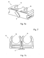
- a further modified embodiment of a fastener 18 is shown, which is similar as the embodiments according to FIGS. 5 and 6 is also provided directly with the foot member 5 for an overlap of edge regions of the opening of the receptacle 1.
- a plurality of clips formed by clamps 19 is arranged side by side.
- FIG. 7 illustrated embodiment with two juxtaposed clamps or receiving elements 19 may of course be provided a correspondingly larger number of juxtaposed receiving elements 19.
- the fastening element 12, 14, 16, 18 and / or the intermediate piece 4 is or are produced, for example, from a plastics material.
Landscapes
- Engineering & Computer Science (AREA)
- General Engineering & Computer Science (AREA)
- Mechanical Engineering (AREA)
- Architecture (AREA)
- Civil Engineering (AREA)
- Structural Engineering (AREA)
- Clamps And Clips (AREA)
- Supports For Pipes And Cables (AREA)
- Insertion Pins And Rivets (AREA)
Applications Claiming Priority (1)
| Application Number | Priority Date | Filing Date | Title |
|---|---|---|---|
| AT0041009U AT11270U1 (de) | 2009-07-01 | 2009-07-01 | Verfahren zum festlegen eines befestigungselements sowie befestigungselement für ein rohrartiges element |
Publications (2)
| Publication Number | Publication Date |
|---|---|
| EP2270943A2 true EP2270943A2 (fr) | 2011-01-05 |
| EP2270943A3 EP2270943A3 (fr) | 2013-11-27 |
Family
ID=42140373
Family Applications (1)
| Application Number | Title | Priority Date | Filing Date |
|---|---|---|---|
| EP10450108.5A Withdrawn EP2270943A3 (fr) | 2009-07-01 | 2010-06-25 | Procédé de fixation d'un élément de fixation ainsi qu'élément de fixation pour un élément de type tubulaire |
Country Status (2)
| Country | Link |
|---|---|
| EP (1) | EP2270943A3 (fr) |
| AT (1) | AT11270U1 (fr) |
Cited By (12)
| Publication number | Priority date | Publication date | Assignee | Title |
|---|---|---|---|---|
| GB2491893A (en) * | 2011-06-17 | 2012-12-19 | Falcon Trunking Systems Ltd | Mounting clip |
| CN106813013A (zh) * | 2016-12-30 | 2017-06-09 | 广州拓讯安防科技有限公司 | 一种煤气管道固定装置 |
| CN107088253A (zh) * | 2016-12-30 | 2017-08-25 | 广州爵诺医疗器械有限公司 | 一种改进型氧气瓶固定装置 |
| CN107091374A (zh) * | 2016-12-30 | 2017-08-25 | 广州拓讯安防科技有限公司 | 一种用于煤气管道的固定装置 |
| CN107091375A (zh) * | 2016-12-30 | 2017-08-25 | 广州拓讯安防科技有限公司 | 一种耐用煤气管道固定装置 |
| CN107091373A (zh) * | 2016-12-30 | 2017-08-25 | 广州拓讯安防科技有限公司 | 一种便用煤气管道固定装置 |
| CN107088252A (zh) * | 2016-12-30 | 2017-08-25 | 广州爵诺医疗器械有限公司 | 一种安全氧气瓶固定装置 |
| CN107091377A (zh) * | 2016-12-30 | 2017-08-25 | 广州拓讯安防科技有限公司 | 一种新型煤气管道固定装置 |
| CN107088251A (zh) * | 2016-12-30 | 2017-08-25 | 广州爵诺医疗器械有限公司 | 一种耐磨氧气瓶固定装置 |
| CN113629625A (zh) * | 2021-10-12 | 2021-11-09 | 江苏昕讯线缆科技有限公司 | 一种能够自适应不同电缆直径的稳定型电缆夹具 |
| EP4293845A1 (fr) * | 2022-06-15 | 2023-12-20 | Unex Aparellaje Electrico S.L. | Piece de fixation pour attacher un cable a un support, et ensemble correspondant |
| WO2024028119A1 (fr) | 2022-08-01 | 2024-02-08 | Hilti Aktiengesellschaft | Raccord |
Families Citing this family (3)
| Publication number | Priority date | Publication date | Assignee | Title |
|---|---|---|---|---|
| FR2985797A1 (fr) * | 2012-01-16 | 2013-07-19 | Peugeot Citroen Automobiles Sa | Collier de serrage multi-fonctions |
| DE102017115388A1 (de) * | 2017-07-10 | 2019-01-10 | Jungheinrich Aktiengesellschaft | Hubgerüst für ein Flurförderzeug |
| US20240413626A1 (en) * | 2023-03-20 | 2024-12-12 | Ted G Brull | Snap-in fasteners for elongated members |
Citations (3)
| Publication number | Priority date | Publication date | Assignee | Title |
|---|---|---|---|---|
| US6209827B1 (en) | 1998-06-22 | 2001-04-03 | Kitagawa Industries Co., Ltd. | Clamp device |
| WO2003064867A1 (fr) | 2002-02-01 | 2003-08-07 | Starquick International Ltd | Fixation de raccords de tuyau |
| US20030213876A1 (en) | 2002-05-14 | 2003-11-20 | Yasuichi Takeuchi | Fixing tool |
Family Cites Families (3)
| Publication number | Priority date | Publication date | Assignee | Title |
|---|---|---|---|---|
| GB2126309B (en) * | 1982-09-03 | 1986-02-19 | Nimlok Ltd | Screen assembly and clip therefor |
| US6835893B2 (en) * | 2003-01-23 | 2004-12-28 | Thomas & Betts International, Inc. | Button fastening device |
| US20070290100A1 (en) * | 2006-06-15 | 2007-12-20 | Panduit Corp. | Cable Mount for Cable Trays |
-
2009
- 2009-07-01 AT AT0041009U patent/AT11270U1/de not_active IP Right Cessation
-
2010
- 2010-06-25 EP EP10450108.5A patent/EP2270943A3/fr not_active Withdrawn
Patent Citations (3)
| Publication number | Priority date | Publication date | Assignee | Title |
|---|---|---|---|---|
| US6209827B1 (en) | 1998-06-22 | 2001-04-03 | Kitagawa Industries Co., Ltd. | Clamp device |
| WO2003064867A1 (fr) | 2002-02-01 | 2003-08-07 | Starquick International Ltd | Fixation de raccords de tuyau |
| US20030213876A1 (en) | 2002-05-14 | 2003-11-20 | Yasuichi Takeuchi | Fixing tool |
Cited By (15)
| Publication number | Priority date | Publication date | Assignee | Title |
|---|---|---|---|---|
| GB2491893A (en) * | 2011-06-17 | 2012-12-19 | Falcon Trunking Systems Ltd | Mounting clip |
| GB2491893B (en) * | 2011-06-17 | 2016-02-10 | Falcon Trunking Systems Ltd | Mounting clip |
| CN106813013A (zh) * | 2016-12-30 | 2017-06-09 | 广州拓讯安防科技有限公司 | 一种煤气管道固定装置 |
| CN107088253A (zh) * | 2016-12-30 | 2017-08-25 | 广州爵诺医疗器械有限公司 | 一种改进型氧气瓶固定装置 |
| CN107091374A (zh) * | 2016-12-30 | 2017-08-25 | 广州拓讯安防科技有限公司 | 一种用于煤气管道的固定装置 |
| CN107091375A (zh) * | 2016-12-30 | 2017-08-25 | 广州拓讯安防科技有限公司 | 一种耐用煤气管道固定装置 |
| CN107091373A (zh) * | 2016-12-30 | 2017-08-25 | 广州拓讯安防科技有限公司 | 一种便用煤气管道固定装置 |
| CN107088252A (zh) * | 2016-12-30 | 2017-08-25 | 广州爵诺医疗器械有限公司 | 一种安全氧气瓶固定装置 |
| CN107091377A (zh) * | 2016-12-30 | 2017-08-25 | 广州拓讯安防科技有限公司 | 一种新型煤气管道固定装置 |
| CN107088251A (zh) * | 2016-12-30 | 2017-08-25 | 广州爵诺医疗器械有限公司 | 一种耐磨氧气瓶固定装置 |
| CN113629625A (zh) * | 2021-10-12 | 2021-11-09 | 江苏昕讯线缆科技有限公司 | 一种能够自适应不同电缆直径的稳定型电缆夹具 |
| CN113629625B (zh) * | 2021-10-12 | 2021-12-17 | 江苏昕讯线缆科技有限公司 | 一种能够自适应不同电缆直径的稳定型电缆夹具 |
| EP4293845A1 (fr) * | 2022-06-15 | 2023-12-20 | Unex Aparellaje Electrico S.L. | Piece de fixation pour attacher un cable a un support, et ensemble correspondant |
| WO2024028119A1 (fr) | 2022-08-01 | 2024-02-08 | Hilti Aktiengesellschaft | Raccord |
| JP2025521956A (ja) * | 2022-08-01 | 2025-07-10 | ヒルティ アクチエンゲゼルシャフト | コネクタ |
Also Published As
| Publication number | Publication date |
|---|---|
| EP2270943A3 (fr) | 2013-11-27 |
| AT11270U1 (de) | 2010-07-15 |
Similar Documents
| Publication | Publication Date | Title |
|---|---|---|
| EP2270943A2 (fr) | Procédé de fixation d'un élément de fixation ainsi qu'élément de fixation pour un élément de type tubulaire | |
| AT507196B1 (de) | Wandverkleidung | |
| EP2236683A1 (fr) | Agencement de rainures de douche pour montage mural | |
| WO2008083781A1 (fr) | Dispositif de fixation d'un capot de recouvrement sur un meuble et meuble équipé de ce dispositif de fixation | |
| DE202011108342U1 (de) | Montagekasten für verteilerlose Fußbodenheizung | |
| EP3312518B1 (fr) | Dispositif de montage du distributeur de fluide | |
| EP2682681B1 (fr) | Dispositif de fixation pour fixer un corps de refroidissement ou de chauffage | |
| EP2523281B1 (fr) | Caniveau de câbles | |
| DE102013105047B4 (de) | Anordnung zum Befestigen einer Schiene | |
| EP3716423B1 (fr) | Outil de montage aligné des inserts d'appareil | |
| EP3626317B1 (fr) | But | |
| DE19832978C2 (de) | Vorrichtung zum Verlegen von Rohren, Leitungen oder dergleichen | |
| DE202010003259U1 (de) | Befestigungssystem zur Halterung von Kabeln und Schläuchen an einem Träger | |
| DE19737893B4 (de) | Installationskanal mit Abdeckung und Potentialausgleichsklammer für den Potentialausgleich zwischen diesen | |
| EP2236886B1 (fr) | Elément d'installation | |
| DE19918690C1 (de) | Vorrichtung zum nachträglichen Anbringen von Halteeinrichtungen, wie ein- oder mehrteiligen Montageschienen, Montagedübeln o. dgl., für Heizkörper o. dgl. | |
| DE102010000095A1 (de) | System zum Erstellen von Balkonen | |
| EP3144443B1 (fr) | Dispositif de fixation de tuiles de toit presentant une feuillure sur des voliges | |
| DE202011051734U1 (de) | Befestigungselement zum Festlegen eines Elements an einer Aufnahme | |
| DE4204895A1 (de) | Montageschiene fuer heizkoerper o. dgl. | |
| DE19925485C1 (de) | Haltevorrichtung für eine Vorrichtung zum nachträglichen Anbringen von Halteeinrichtungen für Heizkörper o. dgl. | |
| DE1921994A1 (de) | Profilstab aus Kunststoff zur Wandbefestigung von elektrischen Draehten und Kabeln | |
| DE1509982C (de) | Außenjalousieverkleidung | |
| DE102007046588B3 (de) | Montagevorrichtung für Zargen, Montagesystem sowie Verfahren zur Montage einer Zarge an einer Maueröffnung | |
| DE3625024C1 (en) | Apparatus for fixing the flexible sequence arrangement elements of a file for storing continuous lists |
Legal Events
| Date | Code | Title | Description |
|---|---|---|---|
| PUAI | Public reference made under article 153(3) epc to a published international application that has entered the european phase |
Free format text: ORIGINAL CODE: 0009012 |
|
| AK | Designated contracting states |
Kind code of ref document: A2 Designated state(s): AL AT BE BG CH CY CZ DE DK EE ES FI FR GB GR HR HU IE IS IT LI LT LU LV MC MK MT NL NO PL PT RO SE SI SK SM TR |
|
| AX | Request for extension of the european patent |
Extension state: BA ME RS |
|
| PUAL | Search report despatched |
Free format text: ORIGINAL CODE: 0009013 |
|
| AK | Designated contracting states |
Kind code of ref document: A3 Designated state(s): AL AT BE BG CH CY CZ DE DK EE ES FI FR GB GR HR HU IE IS IT LI LT LU LV MC MK MT NL NO PL PT RO SE SI SK SM TR |
|
| AX | Request for extension of the european patent |
Extension state: BA ME RS |
|
| RIC1 | Information provided on ipc code assigned before grant |
Ipc: F16L 3/12 20060101ALI20131018BHEP Ipc: F16L 3/24 20060101ALI20131018BHEP Ipc: F16L 3/13 20060101ALI20131018BHEP Ipc: H02G 3/04 20060101ALN20131018BHEP Ipc: F16L 3/237 20060101ALI20131018BHEP Ipc: F16B 21/02 20060101ALN20131018BHEP Ipc: H02G 3/32 20060101AFI20131018BHEP |
|
| STAA | Information on the status of an ep patent application or granted ep patent |
Free format text: STATUS: THE APPLICATION IS DEEMED TO BE WITHDRAWN |
|
| 18D | Application deemed to be withdrawn |
Effective date: 20140528 |