EP2270345B1 - Kugelgewindetrieb mit Axiallager - Google Patents
Kugelgewindetrieb mit Axiallager Download PDFInfo
- Publication number
- EP2270345B1 EP2270345B1 EP10167897A EP10167897A EP2270345B1 EP 2270345 B1 EP2270345 B1 EP 2270345B1 EP 10167897 A EP10167897 A EP 10167897A EP 10167897 A EP10167897 A EP 10167897A EP 2270345 B1 EP2270345 B1 EP 2270345B1
- Authority
- EP
- European Patent Office
- Prior art keywords
- spindle
- threaded spindle
- bearing
- ball
- axial
- Prior art date
- Legal status (The legal status is an assumption and is not a legal conclusion. Google has not performed a legal analysis and makes no representation as to the accuracy of the status listed.)
- Not-in-force
Links
- 238000005096 rolling process Methods 0.000 claims abstract description 12
- 230000014759 maintenance of location Effects 0.000 claims 2
- 230000000717 retained effect Effects 0.000 claims 1
- 210000002105 tongue Anatomy 0.000 description 10
- 239000011324 bead Substances 0.000 description 9
- 238000006073 displacement reaction Methods 0.000 description 3
- 239000000463 material Substances 0.000 description 2
- 239000002184 metal Substances 0.000 description 2
- 208000010543 22q11.2 deletion syndrome Diseases 0.000 description 1
- 238000013459 approach Methods 0.000 description 1
- 230000015572 biosynthetic process Effects 0.000 description 1
- 238000004049 embossing Methods 0.000 description 1
- 238000009434 installation Methods 0.000 description 1
- 238000000034 method Methods 0.000 description 1
- 238000012986 modification Methods 0.000 description 1
- 230000004048 modification Effects 0.000 description 1
- 230000007935 neutral effect Effects 0.000 description 1
- 230000002093 peripheral effect Effects 0.000 description 1
- 238000007493 shaping process Methods 0.000 description 1
- 230000007704 transition Effects 0.000 description 1
Images


Classifications
-
- F—MECHANICAL ENGINEERING; LIGHTING; HEATING; WEAPONS; BLASTING
- F16—ENGINEERING ELEMENTS AND UNITS; GENERAL MEASURES FOR PRODUCING AND MAINTAINING EFFECTIVE FUNCTIONING OF MACHINES OR INSTALLATIONS; THERMAL INSULATION IN GENERAL
- F16C—SHAFTS; FLEXIBLE SHAFTS; ELEMENTS OR CRANKSHAFT MECHANISMS; ROTARY BODIES OTHER THAN GEARING ELEMENTS; BEARINGS
- F16C35/00—Rigid support of bearing units; Housings, e.g. caps, covers
- F16C35/04—Rigid support of bearing units; Housings, e.g. caps, covers in the case of ball or roller bearings
- F16C35/06—Mounting or dismounting of ball or roller bearings; Fixing them onto shaft or in housing
-
- F—MECHANICAL ENGINEERING; LIGHTING; HEATING; WEAPONS; BLASTING
- F16—ENGINEERING ELEMENTS AND UNITS; GENERAL MEASURES FOR PRODUCING AND MAINTAINING EFFECTIVE FUNCTIONING OF MACHINES OR INSTALLATIONS; THERMAL INSULATION IN GENERAL
- F16C—SHAFTS; FLEXIBLE SHAFTS; ELEMENTS OR CRANKSHAFT MECHANISMS; ROTARY BODIES OTHER THAN GEARING ELEMENTS; BEARINGS
- F16C19/00—Bearings with rolling contact, for exclusively rotary movement
- F16C19/22—Bearings with rolling contact, for exclusively rotary movement with bearing rollers essentially of the same size in one or more circular rows, e.g. needle bearings
- F16C19/30—Bearings with rolling contact, for exclusively rotary movement with bearing rollers essentially of the same size in one or more circular rows, e.g. needle bearings for axial load mainly
-
- F—MECHANICAL ENGINEERING; LIGHTING; HEATING; WEAPONS; BLASTING
- F16—ENGINEERING ELEMENTS AND UNITS; GENERAL MEASURES FOR PRODUCING AND MAINTAINING EFFECTIVE FUNCTIONING OF MACHINES OR INSTALLATIONS; THERMAL INSULATION IN GENERAL
- F16C—SHAFTS; FLEXIBLE SHAFTS; ELEMENTS OR CRANKSHAFT MECHANISMS; ROTARY BODIES OTHER THAN GEARING ELEMENTS; BEARINGS
- F16C33/00—Parts of bearings; Special methods for making bearings or parts thereof
- F16C33/30—Parts of ball or roller bearings
- F16C33/46—Cages for rollers or needles
- F16C33/4605—Details of interaction of cage and race, e.g. retention or centring
-
- F—MECHANICAL ENGINEERING; LIGHTING; HEATING; WEAPONS; BLASTING
- F16—ENGINEERING ELEMENTS AND UNITS; GENERAL MEASURES FOR PRODUCING AND MAINTAINING EFFECTIVE FUNCTIONING OF MACHINES OR INSTALLATIONS; THERMAL INSULATION IN GENERAL
- F16C—SHAFTS; FLEXIBLE SHAFTS; ELEMENTS OR CRANKSHAFT MECHANISMS; ROTARY BODIES OTHER THAN GEARING ELEMENTS; BEARINGS
- F16C33/00—Parts of bearings; Special methods for making bearings or parts thereof
- F16C33/30—Parts of ball or roller bearings
- F16C33/46—Cages for rollers or needles
- F16C33/54—Cages for rollers or needles made from wire, strips, or sheet metal
- F16C33/542—Cages for rollers or needles made from wire, strips, or sheet metal made from sheet metal
- F16C33/543—Cages for rollers or needles made from wire, strips, or sheet metal made from sheet metal from a single part
-
- F—MECHANICAL ENGINEERING; LIGHTING; HEATING; WEAPONS; BLASTING
- F16—ENGINEERING ELEMENTS AND UNITS; GENERAL MEASURES FOR PRODUCING AND MAINTAINING EFFECTIVE FUNCTIONING OF MACHINES OR INSTALLATIONS; THERMAL INSULATION IN GENERAL
- F16H—GEARING
- F16H25/00—Gearings comprising primarily only cams, cam-followers and screw-and-nut mechanisms
- F16H25/18—Gearings comprising primarily only cams, cam-followers and screw-and-nut mechanisms for conveying or interconverting oscillating or reciprocating motions
- F16H25/20—Screw mechanisms
- F16H25/24—Elements essential to such mechanisms, e.g. screws, nuts
-
- F—MECHANICAL ENGINEERING; LIGHTING; HEATING; WEAPONS; BLASTING
- F16—ENGINEERING ELEMENTS AND UNITS; GENERAL MEASURES FOR PRODUCING AND MAINTAINING EFFECTIVE FUNCTIONING OF MACHINES OR INSTALLATIONS; THERMAL INSULATION IN GENERAL
- F16D—COUPLINGS FOR TRANSMITTING ROTATION; CLUTCHES; BRAKES
- F16D2125/00—Components of actuators
- F16D2125/18—Mechanical mechanisms
- F16D2125/20—Mechanical mechanisms converting rotation to linear movement or vice versa
- F16D2125/34—Mechanical mechanisms converting rotation to linear movement or vice versa acting in the direction of the axis of rotation
- F16D2125/40—Screw-and-nut
-
- F—MECHANICAL ENGINEERING; LIGHTING; HEATING; WEAPONS; BLASTING
- F16—ENGINEERING ELEMENTS AND UNITS; GENERAL MEASURES FOR PRODUCING AND MAINTAINING EFFECTIVE FUNCTIONING OF MACHINES OR INSTALLATIONS; THERMAL INSULATION IN GENERAL
- F16H—GEARING
- F16H25/00—Gearings comprising primarily only cams, cam-followers and screw-and-nut mechanisms
- F16H25/18—Gearings comprising primarily only cams, cam-followers and screw-and-nut mechanisms for conveying or interconverting oscillating or reciprocating motions
- F16H25/20—Screw mechanisms
- F16H25/22—Screw mechanisms with balls, rollers, or similar members between the co-operating parts; Elements essential to the use of such members
- F16H25/2204—Screw mechanisms with balls, rollers, or similar members between the co-operating parts; Elements essential to the use of such members with balls
-
- Y—GENERAL TAGGING OF NEW TECHNOLOGICAL DEVELOPMENTS; GENERAL TAGGING OF CROSS-SECTIONAL TECHNOLOGIES SPANNING OVER SEVERAL SECTIONS OF THE IPC; TECHNICAL SUBJECTS COVERED BY FORMER USPC CROSS-REFERENCE ART COLLECTIONS [XRACs] AND DIGESTS
- Y10—TECHNICAL SUBJECTS COVERED BY FORMER USPC
- Y10T—TECHNICAL SUBJECTS COVERED BY FORMER US CLASSIFICATION
- Y10T74/00—Machine element or mechanism
- Y10T74/18—Mechanical movements
- Y10T74/18568—Reciprocating or oscillating to or from alternating rotary
- Y10T74/18576—Reciprocating or oscillating to or from alternating rotary including screw and nut
Definitions
- the present invention relates to a ball screw, with a threaded spindle arranged on a spindle nut.
- a relative rotation between the spindle nut and the threaded spindle is converted into an axial relative displacement between the threaded spindle and the spindle nut.
- a disc brake system of a vehicle has become known in which a brake caliper engages around a brake disc, wherein the brake disc can be clamped between the brake pads by a brake piston is pressed against one of the brake pads.
- the brake piston is connected to a spindle nut of a ball screw, which is arranged with the interposition of balls on a threaded spindle.
- the threaded spindle can be set in rotation by means of an electric motor, wherein under the relative rotation between the threaded spindle and the spindle nut, the brake piston connected to the spindle nut can be displaced axially relative to the threaded spindle in the direction of the brake linings.
- the threaded spindle is mounted on a housing of the braking device via a thrust bearing, so that the axial braking force exerted by the brake piston can be introduced into the housing via this thrust bearing.
- the thrust bearing has in this embodiment a plurality of bearing parts: a WälzSystemkranz, which is formed of a plurality of circumferentially distributed rolling elements, optionally a Axiallagerhanfig, in the pockets of the rolling elements are arranged, and optionally thrust washers on both sides of the rolling elements.
- Axial maybelzlager is placed on the threaded spindle and the pre-assembled ball screw is finally inserted into the housing.
- axial roller bearings consist of a large number of individual parts, so that a large number of assembly steps are required when mounting such brake devices.
- US 6,739,436 B1 discloses a screw actuator having a ball screw whose threaded spindle is supported via a thrust bearing on an actuator head.
- the thrust bearing has a arranged at one end of the threaded spindle radial flange, and a thrust washer and arranged between the radial flange and the thrust bearing balls, which can roll on mutually facing raceways of the radial flange and the Axiallagercase.
- the thrust washer is held captive as a bearing part on the radial flange by means of a component which engages in recesses of the bearing part and the radial flange. As a captive a separate component is therefore provided.
- Object of the present invention was to provide a ball screw according to the features of the preamble of claim 1, which is easy to assemble.
- this object has been achieved by the ball screw drive according to claim 1.
- the rotatably arranged relative to the threaded bearing part bearing part is arranged over a captive on the threaded spindle or on a fixedly connected to the threaded shaft portion, the stocked with rolling Axiallagerkarfig can be preassembled on the threaded spindle, so that the ball screw with this preassembled Bearing part can be installed directly without further installation measures, for example, in a housing. Assembly errors are excluded.
- resiliently deflectable detents or fingers or other snap means are provided which engage in a provided on the threaded spindle receptacle, so that the bearing part is held captive.
- the provided on the threaded spindle receptacle can be formed for example by a circumferential annular groove, but also by an embossing, in which, for example, by targeted displacement of material of the threaded spindle a circumferential bead can be generated, so that the bearing part through the bead properly in the axial direction the threaded spindle is held.
- the thrust bearing is designed by an axial roller bearing, which provides a Axiallagerhanfig distributed over the circumference arranged pockets for receiving the rolling elements, said Axiallagerkarfig is provided with detents formed for example by tongues, which engage in a receptacle of the threaded spindle.
- These tongues are preferably resilient, so that when pushing the Axiallagerrithfig on the threaded spindle these tongues engage under rebounding in this recording.
- This catch can be designed as arranged on the inner circumference of the Axiallagerkarfig cage board.
- this cage board is then formed so thin-walled that it has resilient properties, to feed radially inward into this recording.
- the cage board can be seen as polygon-shaped along the spindle axis and with its elastically expandable Polygon tone in the Intervene recording.
- the thrust bearing may have a thrust washer provided with an axial bearing surface, which is provided with a peripheral effective stop for the spindle nut.
- this circumferentially effective stop prevents unwanted tightening of the spindle nut when it rests on the spindle disc; because before the spindle nut can be braced axially against this spindle disc by a screwing, engages the circumferentially effective stop, which prevents further relative rotation between the spindle nut and the spindle disc.
- this spindle disk may be held positively in both directions of rotation, but to be arranged on the threaded spindle in a wobble-capable manner.
- the wobble-capable arrangement prevents unwanted tilting of individual components, so that proper operation of the ball screw according to the invention can be ensured.
- the legs of the brake caliper can be widened under the axially effective braking force, the angularly adjustable spindle disc adapts to this widening and ensures perfect operation.
- the form-locking in the directions of rotation arrangement of the spindle disk is useful if between the spindle disk and the spindle nut, a stop is effective, which can transmit a torque when striking.
- the spindle disk is preferably supported axially on a support bearing.
- This support bearing can be implemented by a trained on the threaded spindle, preferably convex shaped shoulder, so that the example provided with a conically shaped bearing surface spindle disk is supported wobble on this convex shoulder.
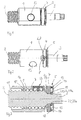
- FIG. 1 shows a ball screw according to the invention in a perspective view.
- a spindle nut 1 is rotatably mounted on a threaded spindle 2.
- the threaded spindle 2 has a tapered shaft portion 3, the is provided with a spindle disk 4 and an axial roller bearing 5.
- the drivable threaded spindle 2 can be supported via the axial roller bearing 5 on a housing not shown here in the axial direction.
- FIG. 2 shows the ball screw according to the invention FIG. 1 , but with a partial section.
- the figure shows that the spindle disk 4 has on its side facing the spindle nut 1 a circumferential wedge-shaped recess 6 which forms a stop 7 for the spindle nut 1.
- the figure shows that the spindle nut 1 is provided on its end face facing the spindle disk 4 with a projection 8 which abuts against the stop 7.
- FIG. 3 shows the ball screw according to the invention in longitudinal section.
- the figure shows that the spindle nut 1 is mounted on the threaded spindle 2 via balls 9.
- the balls 9 roll on helically wound around the spindle axis ball grooves 10,11, which are formed on the ball nut 1 and the threaded spindle 2.
- These ball grooves 10,11 limit endless ball channels 12 in which the balls 9 rotate endlessly.
- This ball screw is provided with a known ball deflection 13, so that the balls 9 are deflected from a beginning to one end of the endless ball channel 12.
- the thrust roller bearing 5 has a thrust bearing cage 13a, in the pockets 14 rollers 15 formed as rolling elements are accommodated. Further, here a thrust washer 16 is provided, which is arranged on the tapered shaft portion 3, and which is provided on its rollers 15 facing the end face with a raceway 17 for the rollers 15. This thrust washer 16 is optional, and may also be omitted if a corresponding raceway for the rollers 15 is formed on the housing already mentioned above.
- the spindle disk 4 is provided at its the rollers 15 facing the end face with a raceway 18 for the rollers 15.
- the spindle disk 4 is arranged via a spline toothing in both directions of rotation on the tapered shaft portion 3 of the threaded spindle 2, wherein, however, the spindle disk 4 is arranged wobble on this tapered shaft portion 3.
- FIG. 3 It can also be seen that a provided between the threaded spindle 2 and the integrally adjoining tapered shaft portion 3 shoulder 19 is designed as a support bearing 20 for the spindle disk 4.
- the power flow in the axial direction is therefore guided by the spindle nut 1 via the balls 9 in the threaded spindle 2 and from there via the shoulder 19 in the spindle disk 4 and the axial roller bearing 5.
- FIGS. 4 and 5 show the thrust bearing cage 13a in two views.
- the two figures show that a plurality of circumferentially distributed pockets 14 are provided for receiving the rollers 15, not shown here.
- the thrust bearing cage 13a per se is made of thin sheet metal in a forming process without cutting.
- On the inner periphery of the thrust bearing cage 13a a plurality of resilient tongues 21 are formed. These resilient tongues 21 engage in an annular groove 22 which is formed on the tapered shaft portion 3 of the ball screw spindle 2 ( FIG. 3 ).
- the tongues 21 consequently form detents 21a and the annular groove 22 forms a receptacle 22a for these detents 21a.
- This thrust bearing cage 13a can be pushed onto the tapered shaft portion 3, wherein finally the resilient tongues 21 snap into this annular groove 22 under a relaxation.
- the annular groove 22 forms a receptacle for the tongues 21.
- the axial bearing cage 13 a is thus held captive on the threaded spindle 2.
- the rollers 15 snap into the pockets 14 of the axial bearing cage 13a, so that the axial bearing cage 13a preassembled with the rollers 15 is designed as a structural unit together with the threaded spindle 2 and the spindle nut 1.
- the resilient tongues 21 together with the annular groove 22 a captive 23rd
- FIG. 6 shows a further ball screw according to the invention in longitudinal section.
- This ball screw according to the invention differs from the ball screw described above substantially by modifications to the spindle disc and the thrust roller bearing, which will be explained in more detail below.
- the threaded spindle 2 is provided at its tapered shaft portion 3 with axially short teeth 25 a, which are part of the spline 25.
- this spindle disc 24 is arranged wobble on the shaft portion 3.
- the axially short teeth 25a favor the wobble of the spindle disk 24.
- the spindle disk 24 is supported on a shoulder 26 which is formed on the threaded spindle 2 in the transition to the stepped shaft portion 3.
- a Axial maybelzlager 27 is also taken captive.
- An axial bearing cage 28 engages with its inner circumference in a formed on the shaft portion 3 receptacle 29, which is limited in the axial directions on the one hand by the spindle disc 24 and on the other hand by a circumferential bead 30 which was formed by material deformation on the shaft portion 3.
- a thrust washer 30a is disposed between the thrust bearing cage 28 and the spindle disc 24. This thrust washer 30a may also be omitted if the spindle disk 24 is already provided with a raceway for the rolling elements of the thrust roller bearing.
- FIGS. 7 and 8 show the spindle disk 24 in longitudinal section and in a view, wherein in both figures clearly an internal toothing 31 can be seen as part of the spline 25.
- the spindle disc 24 is provided with a cone opening 40 which is adapted to the shoulder 26 of the threaded spindle 2 and a tumbling of the spindle disc 24 allows.
- the spindle disc 24 is provided on its spindle nut 1 facing the end face with two circumferentially arranged, axially wedge-shaped recesses 32, each ending at a stop 33. Not further shown projections on the spindle nut 1 engage in these recesses 32 and strike against these stops 33, before an axial distortion between the spindle nut 1 and the thrust washer 24 can use.
- FIGS. 9 and 10 show the thrust bearing cage 28 in a view and in a sectional view. Especially FIG. 9 shows distributed in the circumferential direction pockets 34 for not shown here rollers as rolling elements.
- This Axiallager kaufig 28 is also made of thin sheet without cutting by forming.
- the inner periphery of the Axiallagerkarfig 28 is formed by a circumferential rim 35, which is not cylindrical, but approximately polygonal shaped.
- FIG. 9 a total of three points P1, P2 and P3 are marked at which this board 35 is farthest from the cage axis. Between these points, the cage board 35 approaches the cage axis, wherein in the present case the section of the cage cage 35 located centrally between two successive points P1, P2, P3 is located closest to the cage axis.
- An imaginary enveloping circle encompassed by the cage board 35 is tangent to the cage board 35 at these central sections. The diameter of this imaginary enveloping circle is smaller than the outer diameter of the bead 30, which is impressed on the shaft portion 3 of the threaded spindle 2.
- the thrust bearing cage 28 is pushed onto the shaft portion 3, wherein the free end of the Käfigbordes 35 facing away from the bead 30.
- the cage board 35 under axial displacement of the thrust bearing cage 28 via the Bead 30 is pushed, the cage board 35 springs with its lying centrally between the points P1, P2, P3 sections radially outward, and finally springs back under relaxation radially inwardly when the free end of the cage board 35 has passed the bead 30.
- These central portions consequently form detents 37, which engage in the receptacle 29.
- the axial bearing cage 28 can then no longer be removed axially from the shaft section 3 without special measures.
- the cage board 35 together with the bead 30 a captive 36 ( FIG. 6 ), which holds the thrust bearing cage 28 captive on the shaft portion 3 of the threaded spindle 2.
- the shaping on the inner circumference of the invention Axiallager tanninfige allows a good inner guide of the cage on the shaft section 3.
- the invention not only facilitates the assembly of the pre-assembled with these Axialskylziagern ball screw, but the captive arranged cage simultaneously holds the spindle disc captive on the threaded spindle 2.
- Die At the shaft portion 3 provided for receiving the Axiallager tanninfig is dimensioned in the axial direction so that the Axiallager kaufig has sufficient axial play, but it is ensured that the spindle disc can not slip away from its seat on the shaft portion 3.
- Ball screws according to the invention are suitable for use in an electromechanical parking or service brake with integrated brake caliper.
- a particular advantage of the invention can also be seen in the fact that no additional components are required for the provision of the captive. Rather, can be provided by the special shape of the Axiallagerkarfigs in conjunction with the special shape of the shaft portion 3 already captive. The formation of this invention Verlierommeen can thus be provided cost neutral.
Landscapes
- Engineering & Computer Science (AREA)
- General Engineering & Computer Science (AREA)
- Mechanical Engineering (AREA)
- Rolling Contact Bearings (AREA)
Description
- Die vorliegende Erfindung betrifft einen Kugelgewindetrieb, mit einer auf einer Gewindespindel angeordneten Spindelmutter. Bei derartigen Kugelgewindetrieben wird eine Relativdrehung zwischen der Spindelmutter und der Gewindespindel in eine axiale Relativverschiebung zwischen der Gewindespindel und der Spindelmutter umgewandelt.
- Aus
DE 40 21 572 A1 beispielsweise ist eine Scheibenbremsanlage eines Fahrzeuges bekannt geworden, bei der eine Bremszange eine Bremsscheibe umgreift, wobei die Bremsscheibe zwischen den Bremsbelägen eingespannt werden kann, indem ein Bremskolben gegen einen der Bremsbeläge angedrückt wird. Der Bremskolben ist mit einer Spindelmutter eines Kugelgewindetriebes verbunden, die unter Zwischenschaltung von Kugeln auf einer Gewindespindel angeordnet ist. Die Gewindespindel kann mittels eines Elektromotors in Rotation versetzt werden, wobei unter der Relativdrehung zwischen der Gewindespindel und der Spindelmutter der mit der Spindelmutter verbundene Bremskolben axial gegenüber der Gewindespindel in Richtung auf die Bremsbeläge verlagert werden kann. Die Gewindespindel ist an einem Gehäuse der Bremseinrichtung über ein Axiallager gelagert, so dass die von dem Bremskolben ausgeübte axiale Bremskraft über dieses Axiallager in das Gehäuse eingeleitet werden kann. Das Axiallager weist bei dieser Ausführung mehrere Lagerteile auf: einen Wälzkörperkranz, die aus einer Vielzahl von über den Umfang verteilt angeordneten Wälzkörpern gebildet ist, gegebenenfalls ein Axiallagerkäfig, in dessen Taschen die Wälzkörper angeordnet sind, und gegebenenfalls Axiallagerscheiben zu beiden Seiten der Wälzkörper. - Bei der Montage derartiger Kugelgewindetriebe insbesondere in derartige Bremseinrichtungen wird üblicherweise das Axialwälzlager auf die Gewindespindel aufgesetzt und der vormontierte Kugelgewindetrieb wird schließlich in das Gehäuse eingesetzt. Beispielsweise Axialwälzlager bestehen aus einer Vielzahl von Einzelteilen, so dass bei der Montage derartiger Bremseinrichtungen eine Vielzahl von Montageschritten erforderlich ist.
-
US 6,739,436 B1 offenbart einen Schraubenaktuator, der einen Kugelgewindetrieb aufweist, dessen Gewindespindel über ein Axiallager an einem Aktuatorkopf abgestützt ist. Das Axiallager weist einen an einem Ende der Gewindespindel angeordneten Radialflansch, sowie eine Axiallagerscheibe und zwischen dem Radialflansch und der Axiallagerscheibe angeordnete Kugeln auf, die an einander zugewandten Laufbahnen des Radialflansches und der Axiallagerscheibe abwälzen können. Die Axiallagerscheibe ist als Lagerteil an dem Radialflansch verliersicher mittels einen Bauteils gehalten, das in Ausnehmungen des Lagerteils sowie des Radialflansches eingreift. Als Verliersicherung ist demzufolge ein separates Bauteil vorgesehen. - Aufgabe der vorliegenden Erfindung war es, einen Kugelgewindetrieb nach den Merkmalen des Oberbegriffs des Anspruchs 1 anzugeben, der einfach zu montieren ist.
- Erfindungsgemäß wurde diese Aufgabe durch den Kugelgewindetrieb gemäß Anspruch 1 gelöst. Dadurch, dass das gegenüber der Gewindespindel drehbar angeordnete Lagerteil über eine Verliersicherung an der Gewindespindel oder an einem fest mit der Gewindespindel verbundenen Wellenabschnitt angeordnet ist, kann der mit Wälzkörpern bestückter Axiallagerkäfig auf die Gewindespindel vormontiert werden, so dass der Kugelgewindetrieb mit diesem vormontierten Lagerteil direkt ohne weitere Montagemaßnahmen beispielsweise in ein Gehäuse eingebaut werden kann. Montagefehler sind hierbei ausgeschlossen.
- Als Verliersicherung sind erfindungsgemäß federelastisch auslenkbare Rasten oder Finger oder sonstige Schnappmittel vorgesehen, die in eine an der Gewindespindel vorgesehene Aufnahme eingreifen, so dass das Lagerteil verliersicher gehalten ist.
- Die an der Gewindespindel vorgesehene Aufnahme kann beispielsweise durch eine umlaufende Ringnut gebildet sein, aber auch durch eine Anprägung, bei der beispielsweise durch gezieltes Versetzen von Material der Gewindespindel ein umlaufender Wulst erzeugt werden kann, so dass das Lagerteil durch den Wulst einwandfrei in axialer Richtung auf der Gewindespindel gehalten ist.
- Bei dem erfindungsgemäßen Kugelgewindetrieb ist der Axiallager durch ein Axialwälzlager ausgeführt, das einen Axiallagerkäfig mit über den Umfang verteilt angeordneten Taschen zur Aufnahme der Wälzkörper versehen, wobei dieser Axiallagerkäfig mit beispielsweise durch Zungen gebildete Rasten versehen ist, die in eine Aufnahme der Gewindespindel eingreifen. Diese Zungen sind vorzugsweise federelastisch ausgebildet, so dass beim Aufschieben des Axiallagerkäfig auf die Gewindespindel diese Zungen unter Ausfedern in diese Aufnahme eingreifen.
- Diese Raste kann als am Innenumfang des Axiallagerkäfig angeordneter Käfigbord ausgebildet sein. Vorzugsweise ist dieser Käfigbord dann derart dünnwandig ausgebildet, dass er federelastische Eigenschaften aufweist, um radial nach innen in diese Aufnahme einzuferdern.
- Der Käfigbord kann entlang der Spindelachse gesehen etwa polygonförmig ausgebildet sein und mit seinen elastisch aufweitbaren Polygonseiten in die Aufnahme eingreifen.
- Das Axiallager kann eine mit einer Axiallagerfläche versehene Spindelscheibe aufweisen, die mit einem umfangsseitig wirksamen Anschlag für die Spindelmutter versehen ist. Bei einem derartig weitergebildeten Kugelgewindetrieb verhindert dieser umfangsseitig wirksame Anschlag ein unerwünschtes Festziehen der Spindelmutter, wenn diese auf die Spindelscheibe aufsetzt; denn bevor die Spindelmutter axial gegen diese Spindelscheibe durch eine Schraubbewegung verspannt werden kann, greift der umfangsseitig wirksame Anschlag, der eine weitere Relativdrehung zwischen der Spindelmutter und der Spindelscheibe verhindert.
- Insbesondere bei Verwendung erfindungsgemäßer Kugelgewindetriebe in Bremseinrichtungen zur Betätigung einer Bremse kann es zweckmäßig sein, dass diese Spindelscheibe zwar in beiden Drehrichtungen formschlüssig gehalten, jedoch taumelfähig auf der Gewindespindel angeordnet ist. Die taumelfähige Anordnung verhindert ein unerwünschtes Verkanten einzelner Bauteile, so dass ein einwandfreier Betrieb des erfindungsgemäßen Kugelgewindetriebes gewährleistet werden kann. Wenn erfindungsemäße Kugelgewindetriebe an Bremszangen montiert werden, können die Schenkel der Bremszange unter der axial wirksamen Bremskraft aufgeweitet werden, die winkeleinstellbare Spindelscheibe passt sich dieser Aufweitung an und gewährleistet einen einwandfreien Betrieb. Die in den Drehrichtungen formschlüssige Anordnung der Spindelscheibe ist zweckmäßig, wenn zwischen der Spindelscheibe und der Spindelmutter ein Anschlag wirksam ist, der ein Drehmoment beim Anschlagen übertragen kann.
- Die Spindelscheibe ist vorzugsweise an einem Stützlager axial abgestützt. Dieses Stützlager kann durch eine an der Gewindespindel ausgebildete, vorzugsweise ballig geformte Schulter umgesetzt sein, so dass die beispielsweise mit einer konisch geformten Lagerfläche versehene Spindelscheibe taumelfähig an dieser balligen Schulter abgestützt ist.
- Nachstehend wird die Erfindung anhand von zwei in insgesamt zehn Figuren abgebildeten Ausführungsbeispielen näher erläutert. Es zeigen:
- Figur 1
- einen erfindungsgemäßen Kugelgewindetrieb in perspekti- vischer Darstellung,
- Figur 2
- den Kugelgewindetrieb aus
Figur 1 mit einem Teilschnitt, - Figur 3
- den erfindungsgemäßen Kugelgewindetrieb aus
Figur 1 im Längsschnitt, - Figuren 4 und 5
- ein Einzelteil des erfindungsgemäßen Kugelgewindetrie- bes aus
Figur 1 , - Figur 6
- einen weiteren erfindungsgemäßen Kugelgewindetrieb im Längsschnitt,
- Figuren 7 und 8
- ein Einzelteil des erfindungsgemäßen Kugelgewindetrie- bes aus
Figur 6 , und - Figuren 9 und 10
- ein weiteres Einzelteil des erfindungsgemäßen Kugelge- windetriebes aus
Figur 6 -
Figur 1 zeigt einen erfindungsgemäßen Kugelgewindetrieb in perspektivischer Darstellung. Eine Spindelmutter 1 ist auf einer Gewindespindel 2 drehbar gelagert. Die Gewindespindel 2 weist einen verjüngten Wellenabschnitt 3 auf, der mit einer Spindelscheibe 4 und einem Axialwälzlager 5 versehen ist. Die antreibbare Gewindespindel 2 kann über das Axialwälzlager 5 an einem hier nicht abgebildeten Gehäuse in axialer Richtung abgestützt werden. -
Figur 2 zeigt den erfindungsgemäßen Kugelgewindetrieb ausFigur 1 , jedoch mit einem Teilabschnitt. Der Figur ist zu entnehmen, dass die Spindelscheibe 4 an ihrer der Spindelmutter 1 zugewandten Seite eine in Umfangsrichtung verlaufende keilförmige Ausnehmung 6 aufweist, die einen Anschlag 7 für die Spindelmutter 1 bildet. Der Figur ist zu entnehmen, dass die Spindelmutter 1 an ihrer der Spindelscheibe 4 zugewandten Stirnseite mit einem Vorsprung 8 versehen ist, der gegen den Anschlag 7 anschlägt. -
Figur 3 zeigt den erfindungsgemäßen Kugelgewindetrieb im Längsschnitt. Der Figur ist zu entnehmen, dass die Spindelmutter 1 über Kugeln 9 auf der Gewindespindel 2 gelagert ist. Die Kugeln 9 wälzen an schraubenförmig um die Spindelachse gewundenen Kugelrillen 10,11 ab, die an der Kugelmutter 1 und an der Gewindespindel 2 ausgebildet sind. Diese Kugelrillen 10,11 begrenzen endlose Kugelkanäle 12, in denen die Kugeln 9 endlos umlaufen. Dieser Kugelgewindetrieb ist mit einer an sich bekannten Kugelumlenkung 13 versehen, so dass die Kugeln 9 von einem Anfang zu einem Ende des endlosen Kugelkanals 12 umgelenkt werden. - Der
Figur 3 ist ferner zu entnehmen, dass das Axialwälzlager 5 einen Axiallagerkäfig 13a aufweist, in dessen Taschen 14 als Wälzkörper ausgebildete Rollen 15 aufgenommen sind. Ferner ist hier eine Axiallagerscheibe 16 vorgesehen, die auf dem verjüngten Wellenabschnitt 3 angeordnet ist, und die an ihrer den Rollen 15 zugewandten Stirnseite mit einer Laufbahn 17 für die Rollen 15 versehen ist. Diese Axiallagerscheibe 16 ist optional, und kann auch wegfallen, wenn an dem bereits oben erwähnten Gehäuse eine entsprechende Laufbahn für die Rollen 15 ausgebildet ist. Der Figur ist ferner zu entnehmen, dass die Spindelscheibe 4 an ihrer den Rollen 15 zugewandten Stirnseite mit einer Laufbahn 18 für die Rollen 15 versehen ist. - Die Spindelscheibe 4 ist über eine Keilverzahnung in beiden Drehrichtungen formschlüssig auf dem verjüngten Wellenabschnitt 3 der Gewindespindel 2 angeordnet, wobei jedoch die Spindelscheibe 4 taumelfähig auf diesem verjüngten Wellenabschnitt 3 angeordnet ist.
-
Figur 3 ist ferner zu entnehmen, dass eine zwischen der Gewindespindel 2 und dem einstückig anschließenden verjüngten Wellenabschnitt 3 vorgesehene Schulter 19 als Stützlager 20 für die Spindelscheibe 4 ausgebildet ist. Der Kraftfluss in axialer Richtung wird demzufolge von der Spindelmutter 1 über die Kugeln 9 in die Gewindespindel 2 und von dort über die Schulter 19 in die Spindelscheibe 4 und das Axialwälzlager 5 geleitet. - Die
Figuren 4 und 5 zeigen den Axiallagerkäfig 13a in zwei Ansichten. Den beiden Figuren ist zu entnehmen, dass eine Vielzahl von über den Umfang verteilt angeordneten Taschen 14 zur Aufnahme der hier nicht abgebildeten Rollen 15 vorgesehen ist. Der Axiallagerkäfig 13a an sich ist aus dünnem Blech in einem Umformprozess spanlos hergestellt. Am Innenumfang des Axiallagerkäfigs 13a sind eine Vielzahl von federnden Zungen 21 ausgebildet. Diese federnden Zungen 21 rasten in eine Ringnut 22 ein, die an dem verjüngten Wellenabschnitt 3 der Kugelgewindespindel 2 ausgebildet ist (Figur 3 ). Die Zungen 21 bilden demzufolge Rasten 21a und die Ringnut 22 bildet eine Aufnahme 22a für diese Rasten 21a. - Dieser Axiallagerkäfig 13a kann auf den verjüngten Wellenabschnitt 3 aufgeschoben werden, wobei schließlich die federnden Zungen 21 in diese Ringnut 22 unter einer Entspannung einschnappen. Die Ringnut 22 bildet eine Aufnahme für die Zungen 21. Der Axiallagerkäfig 13a ist somit verliersicher an der Gewindespindel 2 gehalten. Üblicherweise schnappen die Rollen 15 in die Taschen 14 des Axiallagerkäfig 13a ein, so dass der mit den Rollen 15 vormontierte Axiallagerkäfig 13a als Baueinheit gemeinsam mit der Gewindespindel 2 und der Spindelmutter 1 ausgebildet ist. Die federnden Zungen 21 bilden gemeinsam mit der Ringnut 22 eine Verliersicherung 23.
-
Figur 6 zeigt einen weiteren erfindungsgemäßen Kugelgewindetrieb im Längsschnitt. Dieser erfindungsgemäßen Kugelgewindetrieb unterscheidet sich von dem zuvor beschriebenen Kugelgewindetrieb im wesentlichen durch Modifizierungen an der Spindelscheibe und an dem Axialwälzlager, was nachstehend näher erläutert wird. - Eine Spindelscheibe 24 ist ebenso wie die zuvor beschriebene Spindelscheibe über eine Keilverzahnung 25 formschlüssig in beiden Drehrichtungen an dem verjüngten Wellenabschnitt 3 der Gewindespindel 2 angeordnet. Der
Figur 6 ist zu entnehmen, dass die Gewindespindel 2 an ihrem verjüngten Wellenabschnitt 3 mit axial kurz bauenden Zähnen 25a versehen ist, die Teil der Keilverzahnung 25 sind. Ebenso wie bei dem zuvor beschriebenen Ausführungsbeispiel ist diese Spindelscheibe 24 taumelfähig auf dem Wellenabschnitt 3 angeordnet. Die axial kurz bauenden Zähne 25a begünstigen die Taumelfähigkeit der Spindelscheibe 24. Die Spindelscheibe 24 ist an einer Schulter 26 abgestützt, die an der Gewindespindel 2 im Übergang zu dem abgesetzten Wellenabschnitt 3 ausgebildet ist. - An der Gewindespindel 2 ist außerdem ein Axialwälzlager 27 verliersicher aufgenommen. Ein Axiallagerkäfig 28 greift mit seinem Innenumfang in eine an dem Wellenabschnitt 3 ausgebildete Aufnahme 29 ein, die in den axialen Richtungen einerseits begrenzt ist durch die Spindelscheibe 24 und andererseits durch einen umlaufenden Wulst 30, der durch Materialumformung an dem Wellenabschnitt 3 erzeugt wurde.
- Der
Figur 6 ist ferner zu entnehmen, dass eine Axiallagerscheibe 30a zwischen dem Axiallagerkäfig 28 und der Spindelscheibe 24 angeordnet ist. Diese Axiallagerscheibe 30a kann auch entfallen, wenn die Spindelscheibe 24 bereits mit einer Laufbahn für die Wälzkörper des Axialwälzlagers versehen ist. - Die
Figuren 7 und 8 zeigen die Spindelscheibe 24 im Längsschnitt und in einer Ansicht, wobei in beiden Figuren deutlich eine Innenverzahnung 31 als Teil der Keilverzahnung 25 zu erkennen ist. An ihrer der Schulter 26 zugewandten Stirnseite ist die Spindelscheibe 24 mit einer Konusöffnung 40 versehen, die an die Schulter 26 der Gewindespindel 2 angepasst ist und ein Taumeln der Spindelscheibe 24 ermöglicht. - Insbesondere der
Figur 8 ist zu entnehmen, dass die Spindelscheibe 24 an ihrer der Spindelmutter 1 zugewandten Stirnseite mit zwei in Umfangsrichtung angeordneten, axial keilförmig verlaufenden Ausnehmungen 32 versehen ist, die jeweils an einem Anschlag 33 enden. Nicht weiter abgebildete Vorsprünge an der Spindelmutter 1 greifen in diese Ausnehmungen 32 ein und schlagen gegen diese Anschläge 33 an, bevor ein axiales Verspannen zwischen der Spindelmutter 1 und der Axiallagerscheibe 24 einsetzen kann. - Die
Figuren 9 und 10 und zeigen den Axiallagerkäfig 28 in einer Ansicht und in einer Schnittdarstellung. InsbesondereFigur 9 zeigt in Umfangsrichtung verteilt angeordnete Taschen 34 für hier nicht abgebildete Rollen als Wälzkörper. Dieser Axiallagerkäfig 28 ist ebenfalls aus dünnem Blech spanlos durch Umformen hergestellt. Der Innenumfang des Axiallagerkäfig 28 ist durch einen umlaufenden Bord 35 gebildet, der jedoch nicht zylindrisch, sondern etwa polygonförmig geformt ist. - In der
Figur 9 sind insgesamt drei Punkte P1, P2 und P3 markiert, an denen dieser Bord 35 am weitesten entfernt von der Käfigachse ist. Zwischen diesen Punkten nähert sich der Käfigbord 35 der Käfigachse, wobei vorliegend der mittig zwischen zwei aufeinanderfolgenden Punkten P1, P2, P3 liegende Abschnitt des Käfigbordes 35 der Käfigachse am nächsten gelegen ist. Ein von dem Käfigbord 35 umfasster gedachter Hüllkreis tangiert den Käfigbord 35 an diesen mittig liegenden Abschnitten. Der Durchmesser dieses gedachten Hüllkreises ist kleiner als der Außendurchmesser des Wulstes 30, der an den Wellenabschnitt 3 der Gewindespindel 2 angeprägt ist. - Der Axiallagerkäfig 28 wird auf den Wellenabschnitt 3 aufgeschoben, wobei das freie Ende des Käfigbordes 35 von dem Wulst 30 abgewandt ist. Wenn der Käfigbord 35 unter axialem Verschieben des Axiallagerkäfigs 28 über den Wulst 30 geschoben wird, federt der Käfigbord 35 mit seinen mittig zwischen den PunktenP1, P2, P3 liegenden Abschnitten radial auswärts, und federt schließlich wieder unter Entspannung radial einwärts , wenn das freie Ende des Käfigbordes 35 den Wulst 30 passiert hat. Diese mittigen Abschnitte bilden demzufolge Rasten 37, die in die Aufnahme 29 einrasten. Der Axiallagerkäfig 28 kann anschließend ohne besondere Maßnahmen nicht mehr axial von dem Wellenabschnitt 3 abgezogen werden. Der Käfigbord 35 bildet gemeinsam mit dem Wulst 30 eine Verliersicherung 36 (
Figur 6 ), die den Axiallagerkäfig 28 verliersicher auf dem Wellenabschnitt 3 der Gewindespindel 2 hält. - Die hier beschriebenen Ausführungsbeispiele zeigen Schnappverbindungen zwischen dem Axiallagerkäfig und dem Wellenabschnitt, die ein leichtes Montieren des Axiallagerkäfig ermöglichen, die jedoch gleichzeitig ein unbeabsichtigtes Demontieren verhindern.
- Die Formgebung am Innenumfang der erfindungsgemäßen Axiallagerkäfige ermöglicht eine gute Innenführung des Käfigs auf dem Wellenabschnitt 3. Mit der Erfindung wird nicht nur eine Montage der mit diesen Axialwälziagern vormontierten Kugelgewindetriebe erleichtert, sondern der verliersicher angeordnete Käfig hält zugleich die Spindelscheibe verliersicher auf der Gewindespindel 2. Die an dem Wellenabschnitt 3 vorgesehene Aufnahme für den Axiallagerkäfig ist dabei in axialer Richtung so bemessen, dass der Axiallagerkäfig ausreichend Axialspiel hat, wobei jedoch sichergestellt ist, dass die Spindelscheibe nicht von ihrem Sitz auf dem Wellenabschnitt 3 wegrutschen kann.
- Während die hier beschriebenen Ausführungsbeispiele Axialwälzlager mit einem Axiallagerkäfig aus Metall zeigen, ist es selbstverständlich möglich, auch Kunststoffkäfige mit erfindungsgemäßen Verliersicherungen vorzusehen.
- Erfindungsgemäße Kugelgewindetriebe eignen sich in günstiger Weise für den Einsatz bei einer elektromechanischen Park - oder Betriebsbremse mit integriertem Bremssattel.
- Ein besonderer Vorteil der Erfindung kann auch darin gesehen werden, dass für die Bereitstellung der Verliersicherung keine zusätzlichen Bauteile erforderlich sind. Vielmehr kann durch die besondere Formgebung des Axiallagerkäfigs im Zusammenspiel mit der besonderen Formgebung des Wellenabschnitts 3 bereits die Verliersicherung bereitgestellt werden. Die Ausbildung dieser erfindungsgemäßen Verliersicherungen kann somit kostenneutral bereitgestellt werden.
-
- 1
- Spindelmutter
- 2
- Gewindespindel
- 3
- Wellenabschnitt
- 4
- Spindelachse
- 5
- Axialwälzlager
- 6
- keilförmigen Ausnehmung
- 7
- Anschlag
- 8
- Vorsprung
- 9
- Kugel
- 10
- Kugelrille
- 11
- Kugelrille
- 12
- Kugelkanal
- 13
- Kugelumlenkung
- 13
- a Axiallagerkäfig
- 14
- Tasche
- 15
- Rolle
- 16
- Axiallagerscheibe
- 17
- Laufbahn
- 18
- Laufbahn
- 19
- Schulter
- 20
- Stützlager
- 21
- Zunge
- 21
- a Raste
- 22
- Ringnut
- 22a
- Aufnahme
- 23
- Verliersicherung
- 24
- Spindelscheibe
- 25
- Keilverzahnung
- 25a
- Zahn
- 26
- Schulter
- 27
- Axialwälzlager
- 28
- Axiallagerkäfig
- 29
- Aufnahme
- 30
- Wulst
- 30a
- Axiallagerscheibe
- 31
- Innenverzahnung
- 32
- Ausnehmung
- 33
- Anschlag
- 34
- Tasche
- 35
- Käfigbord
- 36
- Verliersicherung
- 37
- Raste
- 40
- konusöffnung
Claims (8)
- Kugelgewindetrieb, mit einer auf einer Gewindespindel (2) angeordneten Spindelmutter (1), und mit einem an der Gewindespindel (2) angeordneten Axiallager mit einem gegenüber der Gewindespindel (2) drehbar angeordneten Lagerteil wobei das Lagerteil über eine Verliersicherung (23, 36) verliersicher an der Gewindespindel (2) angeordnet ist, dadurch gekennzeichnet, dass das Axiallager als auf der Gewindespindel (2) angeordnetes Axialwälzlager (5, 27) ausgeführt ist, dessen das Lagerteil bildender Axiallagerkäfig (13a, 28) mit über den Umfang verteilt angeordneten Taschen (14, 34) versehen ist, in denen Wälzkörper angeordnet sind, wobei der Axiallagerkäfig (13a, 28) mit einer Raste (21a, 37) versehen ist, die in eine Aufnahme (22a, 29) der Gewindespindel (2) eingreift.
- Kugelgewindetrieb nach Anspruch 1, bei dem die Raste (21 a, 37) am Innenumfang des Axiallagerkäfigs (13a, 28) ausgebildet ist.
- Kugelgewindetrieb nach Anspruch 2, bei dem ein an dem Innenumfang ausgebildeter Käfigbord (35) entlang der Spindelachse gesehen etwa polygonförmig ausgebildet ist, der mit seinen elastisch aufweitbaren Polygonseiten in die Aufnahme (22a, 29) eingreift.
- Kugelgewindetrieb nach Anspruch 1, bei dem das Axiallager eine mit einer Axiallagerfläche versehene Spindelscheibe (4, 24) mit einem umfangsseitig wirksamen Anschlag (7, 33) für die Spindelmutter (1) aufweist.
- Kugelgewindetrieb nach Anspruch 4, bei dem die Spindelscheibe (4, 24) auf der Spindelachse in beiden Drehrichtungen formschlüssig, aber taumelfähig auf der Gewindespindel (2) angeordnet ist.
- Kugelgewindetrieb nach Anspruch 5, bei dem die Spindelscheibe (4, 24) an einem Stützlager (20) axial abgestützt ist.
- Kugelgewindetrieb nach Anspruch 6, bei dem das Stützlager durch eine an der Gewindespindel (2) ausgebildete Schulter (19, 26) gebildet ist.
- Kugelgewindetrieb nach Anspruch 1, bei dem die Verliersicherung (23, 36) Schnappmittel aufweist, die in eine Aufnahme (22a, 29) der Gewindespindel (2) einschnappen.
Applications Claiming Priority (1)
| Application Number | Priority Date | Filing Date | Title |
|---|---|---|---|
| DE102009031709A DE102009031709A1 (de) | 2009-07-04 | 2009-07-04 | Kugelgewindetrieb mit Axiallager |
Publications (2)
| Publication Number | Publication Date |
|---|---|
| EP2270345A1 EP2270345A1 (de) | 2011-01-05 |
| EP2270345B1 true EP2270345B1 (de) | 2012-01-04 |
Family
ID=42732006
Family Applications (1)
| Application Number | Title | Priority Date | Filing Date |
|---|---|---|---|
| EP10167897A Not-in-force EP2270345B1 (de) | 2009-07-04 | 2010-06-30 | Kugelgewindetrieb mit Axiallager |
Country Status (5)
| Country | Link |
|---|---|
| US (1) | US20110011191A1 (de) |
| EP (1) | EP2270345B1 (de) |
| AT (1) | ATE540230T1 (de) |
| DE (1) | DE102009031709A1 (de) |
| ES (1) | ES2377493T3 (de) |
Cited By (2)
| Publication number | Priority date | Publication date | Assignee | Title |
|---|---|---|---|---|
| US10295004B2 (en) | 2017-02-16 | 2019-05-21 | Akebono Brake Industry Co., Ltd. | Hydraulically-adjustable rotary to linear stage mechanism |
| US10428888B2 (en) | 2017-10-30 | 2019-10-01 | Akebono Brake Industry Co., Ltd. | Brake system |
Families Citing this family (13)
| Publication number | Priority date | Publication date | Assignee | Title |
|---|---|---|---|---|
| BR112012000786A2 (pt) * | 2009-07-15 | 2016-02-23 | Sanofi Aventis Deutschland | conjunto de mancal de impulso, sistema de direção, e dispositivo de envio de medicamento |
| US9182022B2 (en) * | 2012-10-17 | 2015-11-10 | Honeywell International Inc. | Ball screw actuator including a stop with an integral guide |
| US9482326B2 (en) | 2013-07-03 | 2016-11-01 | Goodrich Corporation | Electromechanical actuator |
| DE202013008175U1 (de) * | 2013-09-14 | 2013-10-29 | Ruia Global Fasteners Ag | Spindel |
| DE102013221363A1 (de) * | 2013-10-22 | 2015-04-23 | Schaeffler Technologies Gmbh & Co. Kg | Axialkäfig für zylindrische Wälzkörper |
| DE102014209646A1 (de) | 2014-05-21 | 2015-11-26 | Schaeffler Technologies AG & Co. KG | Gewindetrieb |
| DE102015201257B3 (de) * | 2015-01-26 | 2016-07-07 | Schaeffler Technologies AG & Co. KG | Kugelgewindetrieb und zugehöriger elektromechanischer Aktuator |
| US10421446B2 (en) * | 2016-03-10 | 2019-09-24 | Lucas Automotive Gmbh | Spindle nut assembly having multiple stop cams |
| KR102383332B1 (ko) * | 2016-11-29 | 2022-04-05 | 현대자동차주식회사 | 볼 스크루 타입 전동식 브레이크 |
| CN111306226B (zh) * | 2020-01-06 | 2025-01-10 | 浙江亚太机电股份有限公司 | 驻车集成式制动卡钳 |
| DE102021106627A1 (de) | 2021-03-18 | 2022-09-22 | Schaeffler Technologies AG & Co. KG | Axialwälzlager und Betätigungseinrichtung für eine Bremseinheit |
| JP7235182B1 (ja) * | 2021-04-15 | 2023-03-08 | 日本精工株式会社 | ボールねじ装置およびその製造方法 |
| DE102022119397A1 (de) * | 2021-11-17 | 2023-05-17 | Zf Active Safety Gmbh | Fahrzeugbremsenaktor und elektromechanische Bremse |
Family Cites Families (14)
| Publication number | Priority date | Publication date | Assignee | Title |
|---|---|---|---|---|
| US3004809A (en) * | 1957-12-19 | 1961-10-17 | Skf Svenska Kullagerfab Ab | Thrust roller bearings |
| GB848745A (en) * | 1958-10-22 | 1960-09-21 | Schaeffler Wilhelm | Improvements in or relating to axial thrust needle bearings |
| US3573510A (en) * | 1969-06-09 | 1971-04-06 | Gen Electric | Cushion thrust washer |
| US4588314A (en) * | 1984-08-15 | 1986-05-13 | Joseph Anscher | Bearing cage |
| JPH0341233A (ja) | 1989-07-06 | 1991-02-21 | Honda Motor Co Ltd | 電動ブレーキ |
| JPH07217607A (ja) * | 1994-02-03 | 1995-08-15 | Smc Corp | 負荷の位置決め装置 |
| EP1058795B1 (de) * | 1998-03-05 | 2003-09-24 | Continental Teves AG & Co. oHG | Betätigungseinheit für eine elektromechanisch betätigbare scheibenbremse |
| US6237434B1 (en) * | 1998-08-31 | 2001-05-29 | Thompson Saginaw Ball Screw Company, Llc. | Ball screw and nut assembly with a nut having a preloaded wiper thread and method of its manufacture and operation |
| NL1013489C2 (nl) * | 1999-11-04 | 2001-05-07 | Skf Eng & Res Centre Bv | Actuator met een hulsvormige steun. |
| US6386764B1 (en) * | 2000-09-07 | 2002-05-14 | The Timken Company | Bearing unitized for handling |
| DE10142644A1 (de) * | 2001-08-31 | 2003-04-03 | Lucas Automotive Gmbh | Motorbetätigbare Scheibenbremse |
| JP2003254327A (ja) * | 2002-03-04 | 2003-09-10 | Ntn Corp | スラスト軸受 |
| US7273134B2 (en) * | 2002-07-26 | 2007-09-25 | Continental Teves Ag & Co. Ohg | Actuation unit for an electromechanically-actuated disc brake |
| WO2005124180A1 (en) * | 2004-06-15 | 2005-12-29 | Pbr Australia Pty Ltd | Actuating mechanism and brake assembly |
-
2009
- 2009-07-04 DE DE102009031709A patent/DE102009031709A1/de not_active Withdrawn
-
2010
- 2010-06-30 AT AT10167897T patent/ATE540230T1/de active
- 2010-06-30 ES ES10167897T patent/ES2377493T3/es active Active
- 2010-06-30 EP EP10167897A patent/EP2270345B1/de not_active Not-in-force
- 2010-07-02 US US12/829,639 patent/US20110011191A1/en not_active Abandoned
Cited By (2)
| Publication number | Priority date | Publication date | Assignee | Title |
|---|---|---|---|---|
| US10295004B2 (en) | 2017-02-16 | 2019-05-21 | Akebono Brake Industry Co., Ltd. | Hydraulically-adjustable rotary to linear stage mechanism |
| US10428888B2 (en) | 2017-10-30 | 2019-10-01 | Akebono Brake Industry Co., Ltd. | Brake system |
Also Published As
| Publication number | Publication date |
|---|---|
| ATE540230T1 (de) | 2012-01-15 |
| EP2270345A1 (de) | 2011-01-05 |
| US20110011191A1 (en) | 2011-01-20 |
| ES2377493T3 (es) | 2012-03-28 |
| DE102009031709A1 (de) | 2011-01-05 |
Similar Documents
| Publication | Publication Date | Title |
|---|---|---|
| EP2270345A1 (de) | Kugelgewindetrieb mit Axiallager | |
| DE102019114618B4 (de) | Lagerbaugruppe und Montageverfahren | |
| DE102013213708A1 (de) | Schneckengetriebe für eine Lenkhilfevorrichtung eines Kraftfahrzeuges mit Spielausgleich | |
| WO2012113640A1 (de) | Kegelrollenlager mit käfig | |
| DE102009042941A1 (de) | Schrägrollenlager ohne Führungsbord am Innenring | |
| EP2155532B1 (de) | Kugelgewindetrieb | |
| EP1714053B1 (de) | Umlenkrolle für einen zugmitteltrieb | |
| WO2006018132A1 (de) | Mehrreihiges schrägkugellager | |
| DE102014216929A1 (de) | Betätigungsvorrichtung für eine Kupplung mit mehrteiligem Rotor und konturierter Drahtfeder | |
| DE102016114677A1 (de) | Haltering für die axiale Fixierung eines Drehlagers einer Lenkvorrichtung für Kraftfahrzeuge | |
| DE102007062363A1 (de) | Schaltgetriebe | |
| DE102016121412A1 (de) | Festlager und Lenkgetriebe | |
| DE19913211B4 (de) | Schrägkugellager | |
| DE202015009020U9 (de) | Getriebeelement | |
| WO2006021273A1 (de) | Radiallageranordnung und radiallager, insbesondere für eine spindellagerung | |
| DE102022120854B4 (de) | Lageranordnung umfassend einen Rotations-Translations-Konverter, insbesondere für eine Bremseinrichtung, sowie Linearstelleinrichtung | |
| EP2450584A2 (de) | Lageranordnung für eine Welle | |
| DE102017108370A1 (de) | Wälzgewindetrieb | |
| DE102015225764A1 (de) | Zahnrad mit Freilauffunktion | |
| DE102014212027A1 (de) | Rampenring für eine Nachstelleinrichtung | |
| EP2554455B1 (de) | Lenksäule mit Lenkungslager und Lenkungslager einer Lenksäule | |
| WO2005015039A1 (de) | Wälzlager zur lagerung einer lenkwelle | |
| DE102021110623B4 (de) | Kombinierte Radial-/Axiallagereinheit mit umformtechnisch hergestellten Komponenten | |
| EP2102041A1 (de) | Lagersitzanordnung zur axialen und radialen fixierung | |
| DE102023100756A1 (de) | Kugelgewindetrieb |
Legal Events
| Date | Code | Title | Description |
|---|---|---|---|
| PUAI | Public reference made under article 153(3) epc to a published international application that has entered the european phase |
Free format text: ORIGINAL CODE: 0009012 |
|
| 17P | Request for examination filed |
Effective date: 20100630 |
|
| AK | Designated contracting states |
Kind code of ref document: A1 Designated state(s): AL AT BE BG CH CY CZ DE DK EE ES FI FR GB GR HR HU IE IS IT LI LT LU LV MC MK MT NL NO PL PT RO SE SI SK SM TR |
|
| AX | Request for extension of the european patent |
Extension state: BA ME RS |
|
| RIC1 | Information provided on ipc code assigned before grant |
Ipc: F16C 33/46 20060101ALI20110804BHEP Ipc: F16D 65/14 20060101ALI20110804BHEP Ipc: F16H 25/22 20060101ALI20110804BHEP Ipc: F16C 19/30 20060101AFI20110804BHEP Ipc: F16C 35/06 20060101ALI20110804BHEP |
|
| GRAP | Despatch of communication of intention to grant a patent |
Free format text: ORIGINAL CODE: EPIDOSNIGR1 |
|
| GRAS | Grant fee paid |
Free format text: ORIGINAL CODE: EPIDOSNIGR3 |
|
| GRAA | (expected) grant |
Free format text: ORIGINAL CODE: 0009210 |
|
| AK | Designated contracting states |
Kind code of ref document: B1 Designated state(s): AL AT BE BG CH CY CZ DE DK EE ES FI FR GB GR HR HU IE IS IT LI LT LU LV MC MK MT NL NO PL PT RO SE SI SK SM TR |
|
| REG | Reference to a national code |
Ref country code: GB Ref legal event code: FG4D Free format text: NOT ENGLISH |
|
| REG | Reference to a national code |
Ref country code: CH Ref legal event code: EP |
|
| REG | Reference to a national code |
Ref country code: AT Ref legal event code: REF Ref document number: 540230 Country of ref document: AT Kind code of ref document: T Effective date: 20120115 |
|
| REG | Reference to a national code |
Ref country code: IE Ref legal event code: FG4D |
|
| REG | Reference to a national code |
Ref country code: DE Ref legal event code: R096 Ref document number: 502010000333 Country of ref document: DE Effective date: 20120308 |
|
| RAP2 | Party data changed (patent owner data changed or rights of a patent transferred) |
Owner name: SCHAEFFLER TECHNOLOGIES AG & CO. KG |
|
| REG | Reference to a national code |
Ref country code: CH Ref legal event code: PFA Owner name: SCHAEFFLER TECHNOLOGIES AG & CO. KG Free format text: SCHAEFFLER TECHNOLOGIES GMBH & CO. KG#INDUSTRIESTRASSE 1-3#91074 HERZOGENAURACH (DE) -TRANSFER TO- SCHAEFFLER TECHNOLOGIES AG & CO. KG#INDUSTRIESTRASSE 1-3#91074 HERZOGENAURACH (DE) |
|
| REG | Reference to a national code |
Ref country code: ES Ref legal event code: FG2A Ref document number: 2377493 Country of ref document: ES Kind code of ref document: T3 Effective date: 20120328 |
|
| REG | Reference to a national code |
Ref country code: NL Ref legal event code: VDEP Effective date: 20120104 |
|
| PG25 | Lapsed in a contracting state [announced via postgrant information from national office to epo] |
Ref country code: SI Free format text: LAPSE BECAUSE OF FAILURE TO SUBMIT A TRANSLATION OF THE DESCRIPTION OR TO PAY THE FEE WITHIN THE PRESCRIBED TIME-LIMIT Effective date: 20120104 |
|
| REG | Reference to a national code |
Ref country code: SK Ref legal event code: T3 Ref document number: E 11302 Country of ref document: SK |
|
| LTIE | Lt: invalidation of european patent or patent extension |
Effective date: 20120104 |
|
| PG25 | Lapsed in a contracting state [announced via postgrant information from national office to epo] |
Ref country code: HR Free format text: LAPSE BECAUSE OF FAILURE TO SUBMIT A TRANSLATION OF THE DESCRIPTION OR TO PAY THE FEE WITHIN THE PRESCRIBED TIME-LIMIT Effective date: 20120104 Ref country code: NO Free format text: LAPSE BECAUSE OF FAILURE TO SUBMIT A TRANSLATION OF THE DESCRIPTION OR TO PAY THE FEE WITHIN THE PRESCRIBED TIME-LIMIT Effective date: 20120404 Ref country code: LT Free format text: LAPSE BECAUSE OF FAILURE TO SUBMIT A TRANSLATION OF THE DESCRIPTION OR TO PAY THE FEE WITHIN THE PRESCRIBED TIME-LIMIT Effective date: 20120104 Ref country code: NL Free format text: LAPSE BECAUSE OF FAILURE TO SUBMIT A TRANSLATION OF THE DESCRIPTION OR TO PAY THE FEE WITHIN THE PRESCRIBED TIME-LIMIT Effective date: 20120104 Ref country code: IS Free format text: LAPSE BECAUSE OF FAILURE TO SUBMIT A TRANSLATION OF THE DESCRIPTION OR TO PAY THE FEE WITHIN THE PRESCRIBED TIME-LIMIT Effective date: 20120504 Ref country code: BG Free format text: LAPSE BECAUSE OF FAILURE TO SUBMIT A TRANSLATION OF THE DESCRIPTION OR TO PAY THE FEE WITHIN THE PRESCRIBED TIME-LIMIT Effective date: 20120404 |
|
| REG | Reference to a national code |
Ref country code: IE Ref legal event code: FD4D |
|
| PG25 | Lapsed in a contracting state [announced via postgrant information from national office to epo] |
Ref country code: PL Free format text: LAPSE BECAUSE OF FAILURE TO SUBMIT A TRANSLATION OF THE DESCRIPTION OR TO PAY THE FEE WITHIN THE PRESCRIBED TIME-LIMIT Effective date: 20120104 Ref country code: FI Free format text: LAPSE BECAUSE OF FAILURE TO SUBMIT A TRANSLATION OF THE DESCRIPTION OR TO PAY THE FEE WITHIN THE PRESCRIBED TIME-LIMIT Effective date: 20120104 Ref country code: LV Free format text: LAPSE BECAUSE OF FAILURE TO SUBMIT A TRANSLATION OF THE DESCRIPTION OR TO PAY THE FEE WITHIN THE PRESCRIBED TIME-LIMIT Effective date: 20120104 Ref country code: PT Free format text: LAPSE BECAUSE OF FAILURE TO SUBMIT A TRANSLATION OF THE DESCRIPTION OR TO PAY THE FEE WITHIN THE PRESCRIBED TIME-LIMIT Effective date: 20120504 Ref country code: GR Free format text: LAPSE BECAUSE OF FAILURE TO SUBMIT A TRANSLATION OF THE DESCRIPTION OR TO PAY THE FEE WITHIN THE PRESCRIBED TIME-LIMIT Effective date: 20120405 |
|
| PG25 | Lapsed in a contracting state [announced via postgrant information from national office to epo] |
Ref country code: CY Free format text: LAPSE BECAUSE OF FAILURE TO SUBMIT A TRANSLATION OF THE DESCRIPTION OR TO PAY THE FEE WITHIN THE PRESCRIBED TIME-LIMIT Effective date: 20120104 |
|
| REG | Reference to a national code |
Ref country code: DE Ref legal event code: R081 Ref document number: 502010000333 Country of ref document: DE Owner name: SCHAEFFLER TECHNOLOGIES AG & CO. KG, DE Free format text: FORMER OWNER: SCHAEFFLER TECHNOLOGIES GMBH & CO. KG, 91074 HERZOGENAURACH, DE Effective date: 20120828 Ref country code: DE Ref legal event code: R081 Ref document number: 502010000333 Country of ref document: DE Owner name: SCHAEFFLER TECHNOLOGIES GMBH & CO. KG, DE Free format text: FORMER OWNER: SCHAEFFLER TECHNOLOGIES GMBH & CO. KG, 91074 HERZOGENAURACH, DE Effective date: 20120828 |
|
| PG25 | Lapsed in a contracting state [announced via postgrant information from national office to epo] |
Ref country code: SE Free format text: LAPSE BECAUSE OF FAILURE TO SUBMIT A TRANSLATION OF THE DESCRIPTION OR TO PAY THE FEE WITHIN THE PRESCRIBED TIME-LIMIT Effective date: 20120104 Ref country code: IE Free format text: LAPSE BECAUSE OF FAILURE TO SUBMIT A TRANSLATION OF THE DESCRIPTION OR TO PAY THE FEE WITHIN THE PRESCRIBED TIME-LIMIT Effective date: 20120104 Ref country code: RO Free format text: LAPSE BECAUSE OF FAILURE TO SUBMIT A TRANSLATION OF THE DESCRIPTION OR TO PAY THE FEE WITHIN THE PRESCRIBED TIME-LIMIT Effective date: 20120104 Ref country code: EE Free format text: LAPSE BECAUSE OF FAILURE TO SUBMIT A TRANSLATION OF THE DESCRIPTION OR TO PAY THE FEE WITHIN THE PRESCRIBED TIME-LIMIT Effective date: 20120104 Ref country code: CZ Free format text: LAPSE BECAUSE OF FAILURE TO SUBMIT A TRANSLATION OF THE DESCRIPTION OR TO PAY THE FEE WITHIN THE PRESCRIBED TIME-LIMIT Effective date: 20120104 Ref country code: DK Free format text: LAPSE BECAUSE OF FAILURE TO SUBMIT A TRANSLATION OF THE DESCRIPTION OR TO PAY THE FEE WITHIN THE PRESCRIBED TIME-LIMIT Effective date: 20120104 |
|
| PLBE | No opposition filed within time limit |
Free format text: ORIGINAL CODE: 0009261 |
|
| STAA | Information on the status of an ep patent application or granted ep patent |
Free format text: STATUS: NO OPPOSITION FILED WITHIN TIME LIMIT |
|
| 26N | No opposition filed |
Effective date: 20121005 |
|
| BERE | Be: lapsed |
Owner name: SCHAEFFLER TECHNOLOGIES G.M.B.H. & CO. KG Effective date: 20120630 |
|
| PG25 | Lapsed in a contracting state [announced via postgrant information from national office to epo] |
Ref country code: MC Free format text: LAPSE BECAUSE OF NON-PAYMENT OF DUE FEES Effective date: 20120630 |
|
| REG | Reference to a national code |
Ref country code: DE Ref legal event code: R097 Ref document number: 502010000333 Country of ref document: DE Effective date: 20121005 |
|
| PG25 | Lapsed in a contracting state [announced via postgrant information from national office to epo] |
Ref country code: MK Free format text: LAPSE BECAUSE OF FAILURE TO SUBMIT A TRANSLATION OF THE DESCRIPTION OR TO PAY THE FEE WITHIN THE PRESCRIBED TIME-LIMIT Effective date: 20120104 |
|
| PG25 | Lapsed in a contracting state [announced via postgrant information from national office to epo] |
Ref country code: BE Free format text: LAPSE BECAUSE OF NON-PAYMENT OF DUE FEES Effective date: 20120630 |
|
| PG25 | Lapsed in a contracting state [announced via postgrant information from national office to epo] |
Ref country code: MT Free format text: LAPSE BECAUSE OF FAILURE TO SUBMIT A TRANSLATION OF THE DESCRIPTION OR TO PAY THE FEE WITHIN THE PRESCRIBED TIME-LIMIT Effective date: 20120104 |
|
| PGFP | Annual fee paid to national office [announced via postgrant information from national office to epo] |
Ref country code: SK Payment date: 20130627 Year of fee payment: 4 |
|
| PGFP | Annual fee paid to national office [announced via postgrant information from national office to epo] |
Ref country code: IT Payment date: 20130630 Year of fee payment: 4 |
|
| PGFP | Annual fee paid to national office [announced via postgrant information from national office to epo] |
Ref country code: DE Payment date: 20130902 Year of fee payment: 4 Ref country code: ES Payment date: 20130724 Year of fee payment: 4 |
|
| PG25 | Lapsed in a contracting state [announced via postgrant information from national office to epo] |
Ref country code: AL Free format text: LAPSE BECAUSE OF FAILURE TO SUBMIT A TRANSLATION OF THE DESCRIPTION OR TO PAY THE FEE WITHIN THE PRESCRIBED TIME-LIMIT Effective date: 20120104 |
|
| PGFP | Annual fee paid to national office [announced via postgrant information from national office to epo] |
Ref country code: FR Payment date: 20130719 Year of fee payment: 4 |
|
| REG | Reference to a national code |
Ref country code: DE Ref legal event code: R081 Ref document number: 502010000333 Country of ref document: DE Owner name: SCHAEFFLER TECHNOLOGIES AG & CO. KG, DE Free format text: FORMER OWNER: SCHAEFFLER TECHNOLOGIES AG & CO. KG, 91074 HERZOGENAURACH, DE Effective date: 20140218 Ref country code: DE Ref legal event code: R081 Ref document number: 502010000333 Country of ref document: DE Owner name: SCHAEFFLER TECHNOLOGIES GMBH & CO. KG, DE Free format text: FORMER OWNER: SCHAEFFLER TECHNOLOGIES AG & CO. KG, 91074 HERZOGENAURACH, DE Effective date: 20140218 |
|
| PG25 | Lapsed in a contracting state [announced via postgrant information from national office to epo] |
Ref country code: TR Free format text: LAPSE BECAUSE OF FAILURE TO SUBMIT A TRANSLATION OF THE DESCRIPTION OR TO PAY THE FEE WITHIN THE PRESCRIBED TIME-LIMIT Effective date: 20120104 |
|
| PG25 | Lapsed in a contracting state [announced via postgrant information from national office to epo] |
Ref country code: LU Free format text: LAPSE BECAUSE OF NON-PAYMENT OF DUE FEES Effective date: 20120630 Ref country code: SM Free format text: LAPSE BECAUSE OF FAILURE TO SUBMIT A TRANSLATION OF THE DESCRIPTION OR TO PAY THE FEE WITHIN THE PRESCRIBED TIME-LIMIT Effective date: 20120104 |
|
| PG25 | Lapsed in a contracting state [announced via postgrant information from national office to epo] |
Ref country code: HU Free format text: LAPSE BECAUSE OF FAILURE TO SUBMIT A TRANSLATION OF THE DESCRIPTION OR TO PAY THE FEE WITHIN THE PRESCRIBED TIME-LIMIT Effective date: 20100630 |
|
| REG | Reference to a national code |
Ref country code: DE Ref legal event code: R119 Ref document number: 502010000333 Country of ref document: DE |
|
| REG | Reference to a national code |
Ref country code: CH Ref legal event code: PL |
|
| GBPC | Gb: european patent ceased through non-payment of renewal fee |
Effective date: 20140630 |
|
| REG | Reference to a national code |
Ref country code: SK Ref legal event code: MM4A Ref document number: E 11302 Country of ref document: SK Effective date: 20140630 |
|
| REG | Reference to a national code |
Ref country code: DE Ref legal event code: R119 Ref document number: 502010000333 Country of ref document: DE Effective date: 20150101 |
|
| REG | Reference to a national code |
Ref country code: FR Ref legal event code: ST Effective date: 20150227 |
|
| PG25 | Lapsed in a contracting state [announced via postgrant information from national office to epo] |
Ref country code: CH Free format text: LAPSE BECAUSE OF NON-PAYMENT OF DUE FEES Effective date: 20140630 Ref country code: IT Free format text: LAPSE BECAUSE OF NON-PAYMENT OF DUE FEES Effective date: 20140630 Ref country code: SK Free format text: LAPSE BECAUSE OF NON-PAYMENT OF DUE FEES Effective date: 20140630 Ref country code: DE Free format text: LAPSE BECAUSE OF NON-PAYMENT OF DUE FEES Effective date: 20150101 Ref country code: LI Free format text: LAPSE BECAUSE OF NON-PAYMENT OF DUE FEES Effective date: 20140630 |
|
| REG | Reference to a national code |
Ref country code: DE Ref legal event code: R081 Ref document number: 502010000333 Country of ref document: DE Owner name: SCHAEFFLER TECHNOLOGIES AG & CO. KG, DE Free format text: FORMER OWNER: SCHAEFFLER TECHNOLOGIES GMBH & CO. KG, 91074 HERZOGENAURACH, DE Effective date: 20150407 |
|
| PG25 | Lapsed in a contracting state [announced via postgrant information from national office to epo] |
Ref country code: GB Free format text: LAPSE BECAUSE OF NON-PAYMENT OF DUE FEES Effective date: 20140630 Ref country code: FR Free format text: LAPSE BECAUSE OF NON-PAYMENT OF DUE FEES Effective date: 20140630 |
|
| REG | Reference to a national code |
Ref country code: ES Ref legal event code: FD2A Effective date: 20150724 |
|
| PG25 | Lapsed in a contracting state [announced via postgrant information from national office to epo] |
Ref country code: ES Free format text: LAPSE BECAUSE OF NON-PAYMENT OF DUE FEES Effective date: 20140701 |
|
| REG | Reference to a national code |
Ref country code: AT Ref legal event code: MM01 Ref document number: 540230 Country of ref document: AT Kind code of ref document: T Effective date: 20150630 |
|
| PG25 | Lapsed in a contracting state [announced via postgrant information from national office to epo] |
Ref country code: AT Free format text: LAPSE BECAUSE OF NON-PAYMENT OF DUE FEES Effective date: 20150630 |
|
| P01 | Opt-out of the competence of the unified patent court (upc) registered |
Effective date: 20230522 |