EP2269701A2 - Dispositif d'exercice vibrant doté d'un centre de gravité bas et de poids modulaires - Google Patents
Dispositif d'exercice vibrant doté d'un centre de gravité bas et de poids modulaires Download PDFInfo
- Publication number
- EP2269701A2 EP2269701A2 EP10251179A EP10251179A EP2269701A2 EP 2269701 A2 EP2269701 A2 EP 2269701A2 EP 10251179 A EP10251179 A EP 10251179A EP 10251179 A EP10251179 A EP 10251179A EP 2269701 A2 EP2269701 A2 EP 2269701A2
- Authority
- EP
- European Patent Office
- Prior art keywords
- modular
- weight
- base
- weights
- vibratory
- Prior art date
- Legal status (The legal status is an assumption and is not a legal conclusion. Google has not performed a legal analysis and makes no representation as to the accuracy of the status listed.)
- Withdrawn
Links
- 230000005484 gravity Effects 0.000 title abstract description 10
- 238000006073 displacement reaction Methods 0.000 claims description 6
- 230000002232 neuromuscular Effects 0.000 abstract description 8
- 210000003205 muscle Anatomy 0.000 description 12
- 230000008901 benefit Effects 0.000 description 7
- 238000012549 training Methods 0.000 description 7
- 230000001133 acceleration Effects 0.000 description 6
- 230000000670 limiting effect Effects 0.000 description 5
- 230000008859 change Effects 0.000 description 4
- 238000013461 design Methods 0.000 description 4
- 238000005516 engineering process Methods 0.000 description 4
- 230000007246 mechanism Effects 0.000 description 4
- 230000000694 effects Effects 0.000 description 3
- 229910001018 Cast iron Inorganic materials 0.000 description 2
- 230000001154 acute effect Effects 0.000 description 2
- 230000003247 decreasing effect Effects 0.000 description 2
- 239000000463 material Substances 0.000 description 2
- 230000037323 metabolic rate Effects 0.000 description 2
- 238000000034 method Methods 0.000 description 2
- 230000003534 oscillatory effect Effects 0.000 description 2
- 230000004044 response Effects 0.000 description 2
- 239000007787 solid Substances 0.000 description 2
- 241001272720 Medialuna californiensis Species 0.000 description 1
- 210000000579 abdominal fat Anatomy 0.000 description 1
- 230000002860 competitive effect Effects 0.000 description 1
- 230000003750 conditioning effect Effects 0.000 description 1
- 210000002808 connective tissue Anatomy 0.000 description 1
- 229940079593 drug Drugs 0.000 description 1
- 239000003814 drug Substances 0.000 description 1
- 239000002360 explosive Substances 0.000 description 1
- 210000003141 lower extremity Anatomy 0.000 description 1
- 238000004519 manufacturing process Methods 0.000 description 1
- 230000013011 mating Effects 0.000 description 1
- 238000010297 mechanical methods and process Methods 0.000 description 1
- 239000002184 metal Substances 0.000 description 1
- 229910052751 metal Inorganic materials 0.000 description 1
- 238000012986 modification Methods 0.000 description 1
- 230000004048 modification Effects 0.000 description 1
- 230000004118 muscle contraction Effects 0.000 description 1
- 230000003387 muscular Effects 0.000 description 1
- 210000001087 myotubule Anatomy 0.000 description 1
- 230000003961 neuronal insult Effects 0.000 description 1
- 230000010355 oscillation Effects 0.000 description 1
- 230000036961 partial effect Effects 0.000 description 1
- 239000004033 plastic Substances 0.000 description 1
- 230000003252 repetitive effect Effects 0.000 description 1
- 230000000284 resting effect Effects 0.000 description 1
- 230000000451 tissue damage Effects 0.000 description 1
- 231100000827 tissue damage Toxicity 0.000 description 1
- 210000001364 upper extremity Anatomy 0.000 description 1
- 230000003966 vascular damage Effects 0.000 description 1
- 230000000007 visual effect Effects 0.000 description 1
Images


Classifications
-
- A—HUMAN NECESSITIES
- A63—SPORTS; GAMES; AMUSEMENTS
- A63B—APPARATUS FOR PHYSICAL TRAINING, GYMNASTICS, SWIMMING, CLIMBING, OR FENCING; BALL GAMES; TRAINING EQUIPMENT
- A63B21/00—Exercising apparatus for developing or strengthening the muscles or joints of the body by working against a counterforce, with or without measuring devices
- A63B21/00196—Exercising apparatus for developing or strengthening the muscles or joints of the body by working against a counterforce, with or without measuring devices using pulsed counterforce, e.g. vibrating resistance means
-
- A—HUMAN NECESSITIES
- A63—SPORTS; GAMES; AMUSEMENTS
- A63B—APPARATUS FOR PHYSICAL TRAINING, GYMNASTICS, SWIMMING, CLIMBING, OR FENCING; BALL GAMES; TRAINING EQUIPMENT
- A63B21/00—Exercising apparatus for developing or strengthening the muscles or joints of the body by working against a counterforce, with or without measuring devices
- A63B21/06—User-manipulated weights
- A63B21/072—Dumb-bells, bar-bells or the like, e.g. weight discs having an integral peripheral handle
- A63B21/0728—Dumb-bells, bar-bells or the like, e.g. weight discs having an integral peripheral handle with means for fixing weights on bars, i.e. fixing olympic discs or bumper plates on bar-bells or dumb-bells
-
- A—HUMAN NECESSITIES
- A63—SPORTS; GAMES; AMUSEMENTS
- A63B—APPARATUS FOR PHYSICAL TRAINING, GYMNASTICS, SWIMMING, CLIMBING, OR FENCING; BALL GAMES; TRAINING EQUIPMENT
- A63B21/00—Exercising apparatus for developing or strengthening the muscles or joints of the body by working against a counterforce, with or without measuring devices
- A63B21/06—User-manipulated weights
- A63B21/072—Dumb-bells, bar-bells or the like, e.g. weight discs having an integral peripheral handle
- A63B21/075—Dumb-bells, bar-bells or the like, e.g. weight discs having an integral peripheral handle with variable weights, e.g. weight systems with weight selecting means for bar-bells or dumb-bells
-
- A—HUMAN NECESSITIES
- A63—SPORTS; GAMES; AMUSEMENTS
- A63B—APPARATUS FOR PHYSICAL TRAINING, GYMNASTICS, SWIMMING, CLIMBING, OR FENCING; BALL GAMES; TRAINING EQUIPMENT
- A63B23/00—Exercising apparatus specially adapted for particular parts of the body
- A63B23/035—Exercising apparatus specially adapted for particular parts of the body for limbs, i.e. upper or lower limbs, e.g. simultaneously
- A63B23/12—Exercising apparatus specially adapted for particular parts of the body for limbs, i.e. upper or lower limbs, e.g. simultaneously for upper limbs or related muscles, e.g. chest, upper back or shoulder muscles
- A63B23/1209—Involving a bending of elbow and shoulder joints simultaneously
- A63B23/1236—Push-ups in horizontal position, i.e. eccentric movement
Definitions
- the present invention lies in the field of resistance training exercise equipment. More specifically, the present disclosure relates to a handheld, vibratory system with a pendulous shape that incorporates modularly connected weights to increase resistance.
- weight lifting In an effort to achieve physical fitness, people of all sizes, ages and physical abilities have used weight lifting, resistance training or conditioning as measures for improving or gaining muscle strength and tone throughout the body by lifting weights against the downward force of gravity.
- weight training free weights that do not limit the user to a specific movement or exercise, such as dumbbells and barbells and a number of variations thereof, are used to perform repetitive lift exercises or are carried or moved during other exercise movements that are performed in conjunction with carrying the weights.
- Free weights are usually available in a set of individual weights of incremental weight amounts or, in the case of dumbbells and barbells, may be comprised of a set of modular plates of incremental weight that are assembled in weight stacks whereby each plate in the stack has a central hole through which the dumbbell or barbell shaft fits.
- the specific amount of weight of the free weights are chosen or adjusted based upon the targeted muscle, the type and desired result of the exercise and the physical ability of the particular user.
- Athletes have used free weight systems, including modular plates, to increase or decrease the counterweight loads during resistance training exercises by adjusting the total weight of the weight stack by increasing or decreasing the size and number of modular plates in the weight stack.
- kettle bells or kettlebells or Russian kettlebells
- a kettle bell is comprised of a ball-like or other shaped weight (e.g., a cannon ball) and a handle.
- Kettle bells are usually constructed of solid cast iron and come in a variety of different and incremental weights associated with their particular mass and girth.
- the kettle bell's low center of mass relative to its handle makes the kettle bell especially functional in exercises that use dynamic swinging or arcing movements designed to incorporate the entire body as a functional "kinetic chain” that transfers strength and power through the muscles in a series of linked movements across a variety of angles.
- dumbbells There also exist a limited number of devices that apply vibration to the upper body musculature using vibrating cables, dumbbells and barbells.
- One form of perturbating dumbbell is available commercially and is referred to as the Galileo® Up-X Dumbbell and is made by the German company, Galileo Systems.
- the oscillatory movements of the muscle are thought to cause the rapid repeating of eccentric/concentric muscle contractions and the stretching of the muscle fibers thereby increasing the metabolic rate of the muscle.
- the vibration capabilities in the existing devices are generally not battery-operated and therefore, power cables are necessary to supply power to the device.
- the freedom to move the device is further constrained by the fact that it is tethered by the power cable. Therefore, it would also be desirable to have a device that effectively imparts a vibration to the upper body muscles that does not require a power cable connection between the device and the power source in order to provide power to the device.
- the term "low center of gravity” or “low center of mass” is defined to mean that more than half of the weight associated with the device is placed below a plane parallel to the floor and bisecting the kettle bell between its upper and lower extremities when the latter of which is resting on the floor in a storage position.
- Such a device allows the dynamic swinging and support exercises that are available with a kettle bell to be combined, along with the added training stimulus provided by vibration.
- the present invention combines a vibratory system with a hand-held resistance device having a pendulous shape of "low center of gravity” or “low center of mass” and adjustable weights and thereby provides the opportunity for a unique, multi-faceted neuromuscular load.
- the vibration caused by the vibratory technology for example, by the device's internal motor, causes alternating accelerations towards and away from the pull of gravity.
- the vibratory oscillations increase the acceleration on the device.
- the increase in acceleration due to the vibratory activity of the device can therefore advantageously increase the force or resistance that the device transfers to the muscles without ever adjusting the object's mass.
- the device of the present invention also provides a unique system for adjusting the weight or mass of the device. In this way, both the mass and acceleration of the device can be used to train the neuromuscular system.
- an exemplary embodiment of the present invention has a vibratory motor mounted towards the bottom of the device as far as possible from the device's handle. This creates a long lever arm from the handle to the vibratory source and therefore, mechanically increases the impact of the vibration during exercise performance. Additionally, the lever arm length, i.e. the length between the handle and the vibratory motor, has been designed so that the device provides the optimal frequencies, i.e. 25-35 Hz, for maximizing the neuromuscular response while minimizing the potential for muscle, connective tissue, neuronal or vascular damage.
- the counterweight system of the present embodiment is attached to the vibratory motor shaft and features two parallel mounted weights. Because the device is intended to move through various planes of motion during exercise and the displacement caused by the vibratory motor is multidirectional, the vibratory stimulus will be applied in multiple directions allowing the neuromuscular improvements to occur in multiple places of movement, as opposed to the single plane of movement response that is common with standard, conventional resistance training equipment.
- the device of the present invention has the potential to offer a more efficient, less time-consuming and more palatable exercise option compared to standard exercise equipment and techniques.
- Embodiments of the present invention provide a vibratory exercise device, comprising an upper portion having a handle portion for gripping the device and a body portion, a base portion capable of being removably attached to the upper portion, a vibratory unit mechanically connected to at least one of the upper and base portions and capable of causing the respective at least one of the upper and base portions to vibrate, and at least one modular weight, the upper and base portions capable of selectively removably holding the at least one modular weight therebetween such that when so holding the at least one modular weight, the upper portion, the at least one modular weight and the base portion have a low center of mass.
- a handheld, vibratory exercise device comprising an upper portion having a handle portion for gripping the device and a body portion, a base portion capable of being removably attached to the upper portion, a vibratory unit mechanically connected to at least one of the upper and base portions and capable of causing the respective at least one of the upper and base portions to vibrate, and a plurality of selectively removable modular weights, the upper and base portions capable of removably holding therebetween the plurality of selectively removable modular weights in a serial vertical stack, the handle and base portions and the plurality of selectively removable modular weights having a pendulum-type ball exterior shape with a low center of mass.
- a handheld, vibratory exercise device comprising an upper portion having a handle portion for gripping the device and a body portion, a base portion capable of being removably attached to the upper portion, the upper and base portions capable of cooperatively holding therebetween at least one selectively removable modular weight, and a vibratory unit mechanically connected to at least one of the upper and base portions and capable of causing the respective at least one of the upper and base portions to vibrate, the upper and base portions together with the vibratory unit having a low center of mass.
- FIG. 1 is an elevational view of the front of a first exemplary embodiment of the exercise device according to the present invention
- FIG. 2 is a left side elevational view of the exercise device of FIG. 1 ;
- FIG. 3 is a top plan view of the exercise device of FIG. 1 ;
- FIG. 4 is a bottom plan view of the exercise device of FIG. 1 ;
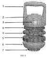
- FIG. 5 is an exploded perspective view from the front left side of the exercise device of FIG. 1 ;
- FIG. 6 is a further exploded view of the exercise device of FIG. 1 ;
- FIG. 7 is an elevational view of the front of a second exemplary embodiment of the exercise device according to the present invention.
- FIG. 8 is an elevational view of the front of a third exemplary embodiment of the exercise device according to the present invention.
- FIGS. 9A to 9G are elevational side views of several exemplary embodiments of the exercise device according to the present invention.
- FIGS. 10A to 10B are elevational side views of the front and side of a fourth exemplary embodiment of the exercise device having two sub-handles according to the present invention.
- FIGS. 11A to 11C are exploded perspective views of the side of a fifth exemplary embodiment of the exercise device according to the present invention.
- FIG. 12A is an elevational view of the front of a sixth exemplary embodiment of the exercise device according to the present invention.
- FIG. 12B is an exploded perspective view of the side of a seventh exemplary embodiment of the exercise device according to the present invention.
- FIG. 13A is an elevational view of the front of an eighth exemplary embodiment of the exercise device according to the present invention.
- FIG. 13B is a top view plan view of the exercise device of FIG. 13A ;
- FIG. 13C is a partial perspective view of the side of the exercise device of FIG. 13A ;
- FIGS. 14A to 14E are additional elevational views of the front of the exercise device of FIG. 13A , including a depiction of the device in use in FIG. 14E ;
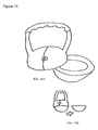
- FIG. 15A is an elevational view of the front of a ninth exemplary embodiment of the exercise device according to the present invention.
- FIG. 15B is an exploded perspective view of the side of the exercise device of FIG. 15A ;
- FIG. 16 is an elevational view of the front of a tenth exemplary embodiment of the exercise device according to the present invention.
- FIG. 17 is an elevational view of the front of an eleventh exemplary embodiment of the exercise device according to the present invention.
- FIG. 18 is an elevational view of the front of a twelfth exemplary embodiment of the exercise device according to the present invention.
- FIGS. 19A and 19B are perspective and elevational views of the side of a thirteenth exemplary embodiment of the exercise device having a pivoting hinge according to the present invention.
- FIGS. 20A and 20B are elevational and perspective views of the front of a fourteenth exemplary embodiment of the exercise device according to the present invention.
- FIG. 21A is an elevational view of the front of a fifteenth exemplary embodiment of the exercise device according to the present invention.
- FIG. 21B is an exploded side view of the exercise device of FIG. 21A ;
- FIG. 22 is an elevational view of the front of a sixteenth exemplary embodiment of the exercise device according to the present invention.
- FIG. 23A is a partially exploded, perspective view and FIG. 23B is an elevational view of the front of a seventeenth exemplary embodiment of the exercise device according to the present invention.
- FIGS. 24A and 24B are elevational views of the front and side of a eighteenth exemplary embodiment of the exercise device according to the present invention.
- FIG. 25A is an exploded, perspective view and FIG. 25B is an elevational view of the front of a nineteenth exemplary embodiment of the exercise device according to the present invention.
- FIG. 26 is an exploded perspective view of the front of a twentieth exemplary embodiment of the exercise device according to the present invention.
- FIG. 27 is an elevational view of the front of a twenty-first exemplary embodiment of the exercise device according to the present invention.
- FIG. 28 is an elevational view of the front of a twenty-second exemplary embodiment of the exercise device according to the present invention.
- FIG. 29A is a partially exploded perspective view
- FIG. 29B is a partially exploded side elevational view
- FIG. 29C is an exploded perspective view of the front of a twenty-third exemplary embodiment of the exercise device according to the present invention.
- FIG. 30 is a side elevational view of a twenty-fourth exemplary embodiment of the exercise device according to the present invention.
- the device of the present invention provides a unique way to apply resistance to the body's musculature.
- the inventive device combines the pendulous power-oriented structure of a kettle bell with a vibratory unit and modular weight plates, the latter of which are used to increase and decrease the total weight of the device.
- the invention is a handheld, vibratory exercise device having a handle that places the center of gravity at a low position, e.g., a position opposite the handle and in an area that is closer to the flat base of the device than the handle when the device is at rest on the ground with the handle oriented upwards at the top of the device. Locating the handle at the top of the device allows it to be used in pendulum-type exercise movements that cannot be performed using dumbbells, barbells, or other resistive devices with the exception of kettle bells.
- the flat base of the device also allows the device to be used for upper body support exercises, for example, push-ups (see, e.g., FIG.
- the inventive device of the present invention has a kettle bell-like shaped shell exterior, but also has a hollow interior that contains a vibratory motor enclosed within the device's superstructure.
- the shell is made of high-impact plastic.
- the device has a supplementary weight system that allows a user to adjust the total weight or the resistance load of the device to the desired amount for a particular exercise.
- the ability to add or remove weights gives the user the ability to change (i.e., increase or decrease, respectively) the resistance felt during the exercise.
- the weights are modular.
- the exercise device 10 is comprised of a handle 1, a pendulum-like ball-shaped body 2, a battery access door 3 that houses a battery for powering the vibratory motor (see e.g., FIG. 6 , described in detail below), a set of modular weights 4, 5 in the exemplary form of plates that are not enclosed in the body 2 and may be removed from the device, a base 6, and a footpad 7.
- the body 2 and the base 6 are shown and described as being half-moon shaped such that when they are assembled together to form the device, their combined shapes form a pendulum-like ball shape.
- the body 2 and/or the base 6 are not limited to this shape and it is contemplated that the body 2 and base 6 can be constructed in a variety of shapes and sizes that effectively result in the exercise device having a low center of mass relative to its handle 1 .
- Alternative designs for the shape and size of the body 2, base 6 and handle 1 are found in various embodiments of the present invention, including, but not limited to, those depicted in FIGS. 7-30 .
- the weight component of the device has been described above as a set of modular weights 4, 5 in the form of plates, it is contemplated that the weight component can be in the form of a single weight or a set of a plurality of weights, and can be of a variety of modular shapes, weight amounts and sizes that can be selectively removable from the body 2 of the device 10 such that the user can change the total weight of the device by adding, removing or interchanging the various weights.
- the device 10 has a set of two modular weights plates 4, 5 of two different weight amounts. If desired, the first modular plate 4 can weigh, for example, 2.5 pounds, and the second modular plate 5 can weigh, for example, 5 pounds. As a result, when both plates 4, 5 are used, the device 10 has a combined total added weight of 7.5 pounds.
- FIG. 5 is an exploded view of the first embodiment of the device of FIG. 1 , which illustrates an exemplary embodiment of the mechanism for assembling the device whereby the modular plate-shaped weights 4, 5 are selectively removable from the body 2 and the base 6 of the device.
- FIG. 6 shows a cover 9 is attached to the bottom base of the body 2.
- the cover 9 has a bottom surface with a non-illustrated boss having a series of exterior threads.
- the top surface of each modular weight plate 4, 5 has a depression with a series of interior threads (not illustrated due to the scale of the drawing) that opposingly correspond to the exterior threads of the cover 9 such that the top surface of the adjacent modular weight plate (in FIG.
- each modular weight plate 4, 5 has a non-illustrated boss with a series of exterior threads that are identical to the exterior threads of the boss of the cover 9 and, accordingly, also opposingly correspond to the interior threads of the depression in the top surface of each modular weight plate.
- the interior threads of the top surface of each weight plate threadingly engage the exterior threads of the adjacent boss at the bottom surface of each weight plate.
- the base 6 of the device is connected with the handle 1, the body 2, and the one or more weight plates 4, 5. Accordingly, in the illustrated exemplary embodiment, the base 6 may be similarly removably attached to the bottom surface of each modular weight plate 4, 5.
- the base 6 is shown as having a depression with a series of interior threads that opposingly correspond to the exterior threads of the boss at the bottom surface of each weight plate such that the base 6 may be threaded onto and removably attached to the bottom surface of the weight plate that is positioned at the bottom-most position in the weight stack.
- This "screw-in" design allows the mass of the device to be easily adjusted to maximize the benefits during different exercises and to match the fitness level of the user during those exercises.
- the modular weight plates 4, 5 can be removably attached between the body 2 and the base 6 of the device in any order.
- the device can be altered to change the total weight and resistance load of the device by adding and removing any combination of 2.5 pounds, 5 pounds and 7.5 pounds in this exemplary embodiment.
- the mechanism described above and shown in FIGS. 1-6 for assembling the device 10 serves as just one illustration of a large number of mechanisms that are contemplated by the present invention for attaching the body 2 to the base 6 of the device.
- the body 2 and base 6 may be formed into corresponding, mating shapes whereby the body 2 is directly removably attached to the base 6 whereby the one or more modular weights are completely enclosed inside the device 10, are not visible from the exterior of the device, and are not a part of the mechanism for interconnecting the body 2 with the base 6.
- one or more latches or other mechanical methods of attaching and securing the body 2 to the base 6, such as a rotating hinge as shown in FIG. 19 may be utilized.
- the body 2 and/or the base 6 may be specifically molded into a shape that is conducive to a hand grip such that a user may easily disassemble the base 6 from the body 2, or vice versa, using his or her hands.
- visual indicators may be applied to the body 2 and/or the base 6 to aid and confirm to the user that the body 2 and the base 6 have been properly assembled and attached to one another.
- a number of ways for securing the one or more modular weights inside or amongst the body 2 and base 6 of the device, based upon the respective shapes of the weights, body 2 and the base 6 of the device, are also contemplated by the present invention.
- one or more pockets, slots, or keyed portions may be formed in the exterior surface of the body 2 and/or the base 6 of the device for mateably holding or containing the one or more modular weights.
- the bottom portion of the base 6 may be flat.
- a tactile, traction-like footpad 7 that may be made of rubber or multiple rubber "feet” may also be incorporated on the bottom portion of the base 6 to further aid in preventing the device from moving around when it is placed on a surface and to prevent the device from damaging the surface.
- This design option allows the device to be used as a support system during exercises such as push-ups or planks thereby allowing the increased benefit of the vibrational overload to be added to these ordinarily mundane exercises.
- the interior of the base 6 may be made to be relatively hollow to reduce the amount of weight that it contributes to the overall total weight of the device and/or to reduce production cost.
- a vibration unit may be incorporated inside the device 10.
- the vibration unit is comprised of a battery-powered motor 12 that is incorporated into the hollow interior of the body 2.
- FIG. 6 shows an exploded view of the motor 12. Attached to a shaft (central axel) (not shown) protruding from either or both ends of the motor 12 are two asymmetrically shaped weights (not shown) designed to cause the entire device to vibrate. The sizes of the attached weights can be varied to change the amplitude of the vibration, as can the size of the motor to accommodate the weights.
- the weights have sufficient mass and displacement to create a displacement of 2-4 mm at a frequency of approximately 28 Hz.
- two opposing battery access doors 3 are shown as being removed from the body 2 to expose their respective battery compartments 18.
- Each of the battery compartments 18 may hold one of two exemplary battery packs 11 that are electrically coupled to the vibration motor 12 thereby providing power to the motor 12.
- a single access door may be used to incorporate the batteries needed in a single compartment. It is desirable that these battery packs 11 are rechargeable and a charging socket may be incorporated into the device in a position opposite the power switch on the body of the device.
- the cover 9 is attached to the bottom of the body 2 and can, if desired, form the floor of the one or more battery compartments 18 in the body 2.
- a combination of large mounting pins 13, motor mounting brackets 14, smaller mounting pins 15, and offset weights 16 may be used.
- the vibratory movement imparted by the motor 12 may be of any suitable displacement amount and frequency for purposes of improving the metabolic rate of the upper body musculature.
- the motor 12 may be capable of applying a displacement of between 2 and 4 mm at a frequency of between 25 and 35 Hz.
- one or more switches or buttons may be provided.
- an ON/OFF switch 8 is provided on the handle 1 of the device.
- the handle may be made in a variety of suitable shapes, thicknesses and sizes that take into account a number of considerations that include, but are not limited to, the type of exercise that should be performed with the device, the particular physical capabilities, grip strength, and endurance of the target user of the device, and the challenges in gripping the device as it vibrates.
- FIGS. 7-30 depict alternative embodiments of the device having a wide range of possible configurations of the handle, including wherein the handle is comprised of more than one sub-handle where it is desirable that a user uses both hands to grip the device (for example, see FIGS. 10A-10B ).
- the handle may be shaped in ways or constructed of materials that are well suited for contact with a human hand and/or a tactile, traction-like grip material may be applied to a portion of the exterior surface of the handle (for example, see FIG. 11 , 14 , 15A , 18 , 22 , and 29A ).
- gaskets 17 can be provided between any of the components of the device. Illustratively, FIG. 6 depicts three gaskets 17 as separating the components of the device. These gaskets 17 separate the metal parts to lessen the friction felt therebetween when the device is in use thereby decreasing the wear of the adjacent parts.
Landscapes
- Health & Medical Sciences (AREA)
- Life Sciences & Earth Sciences (AREA)
- Biophysics (AREA)
- Orthopedic Medicine & Surgery (AREA)
- General Health & Medical Sciences (AREA)
- Physical Education & Sports Medicine (AREA)
- Rehabilitation Tools (AREA)
- Golf Clubs (AREA)
- Percussion Or Vibration Massage (AREA)
- Toys (AREA)
Applications Claiming Priority (1)
| Application Number | Priority Date | Filing Date | Title |
|---|---|---|---|
| US22127609P | 2009-06-29 | 2009-06-29 |
Publications (2)
| Publication Number | Publication Date |
|---|---|
| EP2269701A2 true EP2269701A2 (fr) | 2011-01-05 |
| EP2269701A3 EP2269701A3 (fr) | 2011-05-04 |
Family
ID=43033130
Family Applications (1)
| Application Number | Title | Priority Date | Filing Date |
|---|---|---|---|
| EP10251179A Withdrawn EP2269701A3 (fr) | 2009-06-29 | 2010-06-29 | Dispositif d'exercice vibrant doté d'un centre de gravité bas et de poids modulaires |
Country Status (3)
| Country | Link |
|---|---|
| US (1) | US8128537B2 (fr) |
| EP (1) | EP2269701A3 (fr) |
| CN (1) | CN101934120A (fr) |
Cited By (3)
| Publication number | Priority date | Publication date | Assignee | Title |
|---|---|---|---|---|
| EP2537565A1 (fr) * | 2011-06-20 | 2012-12-26 | Escape Fitness Limited | Kettlebell et procédé de fabrication de kettlebell |
| WO2019149883A1 (fr) * | 2018-02-02 | 2019-08-08 | Jaxamo Ltd | Appareils pour exercices, systèmes et procédés associés |
| US10695614B2 (en) | 2018-10-15 | 2020-06-30 | Jaxamo Ltd | System and method for monitoring or assessing physical fitness from disparate exercise devices and activity trackers |
Families Citing this family (47)
| Publication number | Priority date | Publication date | Assignee | Title |
|---|---|---|---|---|
| US9022906B1 (en) * | 2011-12-22 | 2015-05-05 | Preston Nelson | Top-loading adjustable weight kettlebell system |
| US20080081744A1 (en) * | 2006-09-28 | 2008-04-03 | Gormley Joseph E | Adjustable Plate Loaded Kettlebell |
| US20110275494A1 (en) * | 2010-05-05 | 2011-11-10 | Robert Radi | Collapsible kettlebell system |
| US8568280B2 (en) * | 2010-08-25 | 2013-10-29 | Ernest Richard MENDOZA | Separable weight adjustable medicine ball |
| USD654971S1 (en) * | 2011-01-13 | 2012-02-28 | Escape Fitness Limited | Kettlebell |
| USD652877S1 (en) * | 2011-07-15 | 2012-01-24 | Icon Ip, Inc. | Kettle bell |
| USD664613S1 (en) * | 2011-07-15 | 2012-07-31 | Icon Ip, Inc. | Kettle bell |
| USD653716S1 (en) * | 2011-08-09 | 2012-02-07 | Chieh-Jen Lin | Kettle dumbbell |
| US20130059701A1 (en) * | 2011-09-03 | 2013-03-07 | Cathy Dawn Santa Cruz | Multi-functional hand held exercise device |
| US8944971B2 (en) | 2013-01-04 | 2015-02-03 | Gary Thomas Shorter | Progressive multi-purpose exercise device |
| EP2969058B1 (fr) | 2013-03-14 | 2020-05-13 | Icon Health & Fitness, Inc. | Appareil d'entraînement musculaire ayant un volant, et procédés associés |
| WO2014153519A1 (fr) * | 2013-03-22 | 2014-09-25 | Marich Mitch | Dispositif d'exercice |
| USD726843S1 (en) * | 2013-10-18 | 2015-04-14 | Logan J. Barton | Kettlebell |
| KR101492112B1 (ko) | 2013-12-02 | 2015-02-10 | 동의대학교 산학협력단 | 운동강도 조절이 용이한 케틀벨 |
| EP3086865B1 (fr) | 2013-12-26 | 2020-01-22 | Icon Health & Fitness, Inc. | Mécanisme de résistance magnétique dans une machine à câble |
| US9216315B1 (en) * | 2014-06-05 | 2015-12-22 | Li-Ling Chang | Multifunctional exercising device |
| WO2015191445A1 (fr) | 2014-06-09 | 2015-12-17 | Icon Health & Fitness, Inc. | Système de câble incorporé dans un tapis roulant |
| USD728040S1 (en) * | 2014-09-27 | 2015-04-28 | Cyrus Peterson | Kettlebell |
| US20160256730A1 (en) * | 2015-03-05 | 2016-09-08 | Mike Bartos | Adjustable weight workout stone |
| US9844695B1 (en) | 2015-03-06 | 2017-12-19 | Gary Thomas Shorter | Multi-configuration upgradable fitness device |
| TWI644702B (zh) | 2015-08-26 | 2018-12-21 | 美商愛康運動與健康公司 | 力量運動機械裝置 |
| US10940360B2 (en) | 2015-08-26 | 2021-03-09 | Icon Health & Fitness, Inc. | Strength exercise mechanisms |
| USD806817S1 (en) * | 2015-09-02 | 2018-01-02 | Kompan A/S | Exercising apparatus |
| US10441840B2 (en) | 2016-03-18 | 2019-10-15 | Icon Health & Fitness, Inc. | Collapsible strength exercise machine |
| US10293211B2 (en) | 2016-03-18 | 2019-05-21 | Icon Health & Fitness, Inc. | Coordinated weight selection |
| US10252109B2 (en) | 2016-05-13 | 2019-04-09 | Icon Health & Fitness, Inc. | Weight platform treadmill |
| US10661114B2 (en) | 2016-11-01 | 2020-05-26 | Icon Health & Fitness, Inc. | Body weight lift mechanism on treadmill |
| US10420978B2 (en) * | 2016-11-03 | 2019-09-24 | Beto Engineering & Marketing Co., Ltd. | Adjustable exercise device |
| USD844718S1 (en) * | 2017-09-11 | 2019-04-02 | Hyper Wear, Inc. | Adjustable fitness kettlebell handle |
| US11529542B2 (en) * | 2018-01-17 | 2022-12-20 | Craig Louis Sisler | Adjustable kettlebell device |
| USD888848S1 (en) * | 2018-02-02 | 2020-06-30 | Jaxamo Ltd | Exercise system |
| USD879888S1 (en) * | 2018-09-06 | 2020-03-31 | Nautilus, Inc. | Kettlebell |
| TWD201095S (zh) * | 2019-07-26 | 2019-11-21 | 雙餘實業股份有限公司 | 壺鈴 |
| US11285352B2 (en) | 2020-01-23 | 2022-03-29 | William Gary Beall | Method of exercise using two-handled container partially filled with liquid |
| USD974502S1 (en) | 2020-01-23 | 2023-01-03 | William Gary Beall | Two-handled exercise device |
| US10792079B1 (en) * | 2020-06-21 | 2020-10-06 | Wael Hamade | Surgical tool |
| CN112842821B (zh) * | 2021-02-01 | 2023-01-13 | 重庆医科大学附属第一医院 | 一种用于预防picc血栓的握力装置 |
| USD918318S1 (en) * | 2021-02-09 | 2021-05-04 | Jianping Liu | Adjustable kettlebell |
| USD969942S1 (en) * | 2021-03-03 | 2022-11-15 | Amber Puchlov | Exercise device |
| US11517784B2 (en) * | 2021-04-27 | 2022-12-06 | Andrew MacKenzie Heckman | Modular kettle-shaped dumbbell |
| US20230046492A1 (en) * | 2021-08-16 | 2023-02-16 | Jeffrey Scott Anderson | Spherical hand exerciser with off-center weighted core |
| USD977040S1 (en) * | 2021-11-18 | 2023-01-31 | Craig Louis Sisler | Adjustable kettlebell |
| USD976345S1 (en) * | 2021-11-18 | 2023-01-24 | Craig Louis Sisler | Adjustable kettlebell |
| CN114272556B (zh) * | 2021-12-03 | 2022-11-18 | 昆山十全塑胶五金产品有限公司 | 具扇状配重块的壶铃 |
| WO2023164168A1 (fr) | 2022-02-25 | 2023-08-31 | Jones, Tyler | Dispositif d'exercice |
| USD1004717S1 (en) | 2022-02-25 | 2023-11-14 | Tyler Jones | Exercise device |
| USD1050309S1 (en) * | 2024-07-05 | 2024-11-05 | Ohfg Technologies(Shanghai) Co., Ltd | Kettlebell base |
Citations (4)
| Publication number | Priority date | Publication date | Assignee | Title |
|---|---|---|---|---|
| US850938A (en) * | 1905-11-16 | 1907-04-23 | John Harvey Kellogg | Exercising apparatus. |
| EP0929348A1 (fr) * | 1996-08-26 | 1999-07-21 | Hans Schiessl | Appareil permettant de stimuler des muscles de l'appareil locomoteur |
| US20070298941A1 (en) * | 2003-05-21 | 2007-12-27 | Norbert Egger | Retrofit Kit for a Training Device and Training Device |
| WO2010121062A1 (fr) * | 2009-04-17 | 2010-10-21 | Wilkinson William T | Exerciseur universel multidirectionnel amélioré pour l'entraînement de la main, du poignet et de l'avant-bras dans des plans multiples, avec résistance réglable |
Family Cites Families (24)
| Publication number | Priority date | Publication date | Assignee | Title |
|---|---|---|---|---|
| US1316683A (en) * | 1919-09-23 | Planckillai h c | ||
| US907965A (en) * | 1908-03-27 | 1908-12-29 | Alan Calvert | Dumb-bell and the like. |
| US1044018A (en) * | 1911-04-14 | 1912-11-12 | Alan Calvert | Dumb and bar bell and ring-weight. |
| US1138196A (en) * | 1912-08-14 | 1915-05-04 | Robert N Diehl | Exercising apparatus. |
| US1422888A (en) * | 1920-12-21 | 1922-07-18 | Leslie C Reeves | Exercising device |
| USD242865S (en) * | 1975-02-21 | 1976-12-28 | Bremshey Aktiengesellschaft | Dumb-bell |
| US4566690A (en) * | 1984-05-10 | 1986-01-28 | Schook Michael N | Dumbell and barbell exercise equipment |
| SU1623671A1 (ru) * | 1988-05-11 | 1991-01-30 | Н. И. Волков и В. Н. Москалев | Гантель |
| SU1662589A1 (ru) * | 1989-06-19 | 1991-07-15 | А.А.Шагиров | Спортивный снар д |
| JPH03155308A (ja) * | 1989-11-11 | 1991-07-03 | Aisin Aw Co Ltd | 電動車両の電源装置 |
| US5072933A (en) * | 1990-03-22 | 1991-12-17 | Diodatics Internationalinc Inc. | Exercising apparatus |
| US5102124A (en) * | 1990-10-25 | 1992-04-07 | Diodati Joseph M | Barbell |
| US5868653A (en) * | 1995-09-01 | 1999-02-09 | Klasen; Heinz | Vibrating barbell |
| JPH09201429A (ja) | 1996-01-30 | 1997-08-05 | Toshiba Corp | ダンベル |
| US5807215A (en) * | 1996-02-09 | 1998-09-15 | Mitsubishi Precision Co., Ltd. | Weight unit with rotatable mass |
| US6039679A (en) * | 1999-08-09 | 2000-03-21 | Yu; Simon S. C. | Electronic dumbbell |
| US20070004558A1 (en) * | 2005-07-01 | 2007-01-04 | Vibrogrip Ab | Vibration unit |
| US7381157B2 (en) * | 2005-12-13 | 2008-06-03 | Diani, Llc | Exercise device and method |
| DE102005062432A1 (de) * | 2005-12-23 | 2007-07-12 | Tremo-Tec Gmbh | Muskelstimulationsgerät |
| US20070270726A1 (en) * | 2006-05-19 | 2007-11-22 | Hsien-Nan Chou | Vibrating device for fitness equipment |
| US20080139370A1 (en) * | 2006-12-12 | 2008-06-12 | Richard Charnitski | Vibrating exercise apparatus |
| ATE536161T1 (de) | 2007-06-22 | 2011-12-15 | Hans Schiessl | Vorrichtung und verfahren für ein training und/oder eine analyse des bewegungsapparats eines benutzers |
| CN201279368Y (zh) * | 2008-09-23 | 2009-07-29 | 期美科技股份有限公司 | 振动哑铃 |
| CN201431732Y (zh) * | 2009-05-18 | 2010-03-31 | 董西攀 | 一种哑铃 |
-
2009
- 2009-11-11 US US12/616,548 patent/US8128537B2/en not_active Expired - Fee Related
-
2010
- 2010-04-21 CN CN2010101537167A patent/CN101934120A/zh active Pending
- 2010-06-29 EP EP10251179A patent/EP2269701A3/fr not_active Withdrawn
Patent Citations (4)
| Publication number | Priority date | Publication date | Assignee | Title |
|---|---|---|---|---|
| US850938A (en) * | 1905-11-16 | 1907-04-23 | John Harvey Kellogg | Exercising apparatus. |
| EP0929348A1 (fr) * | 1996-08-26 | 1999-07-21 | Hans Schiessl | Appareil permettant de stimuler des muscles de l'appareil locomoteur |
| US20070298941A1 (en) * | 2003-05-21 | 2007-12-27 | Norbert Egger | Retrofit Kit for a Training Device and Training Device |
| WO2010121062A1 (fr) * | 2009-04-17 | 2010-10-21 | Wilkinson William T | Exerciseur universel multidirectionnel amélioré pour l'entraînement de la main, du poignet et de l'avant-bras dans des plans multiples, avec résistance réglable |
Non-Patent Citations (1)
| Title |
|---|
| COCHRANE D.J. ET AL.: "The Acute Effect of Vibration Exercise on Concentric Muscular Characteristics", JOURNAL OF SCIENCE AND MEDICINE IN SPORT, vol. 11, no. 6, 2008, pages 527 - 534 |
Cited By (7)
| Publication number | Priority date | Publication date | Assignee | Title |
|---|---|---|---|---|
| EP2537565A1 (fr) * | 2011-06-20 | 2012-12-26 | Escape Fitness Limited | Kettlebell et procédé de fabrication de kettlebell |
| WO2019149883A1 (fr) * | 2018-02-02 | 2019-08-08 | Jaxamo Ltd | Appareils pour exercices, systèmes et procédés associés |
| US10463906B2 (en) | 2018-02-02 | 2019-11-05 | Jaxamo Ltd. | Exercise devices, systems, and methods |
| US10786700B2 (en) | 2018-02-02 | 2020-09-29 | Jaxamo Ltd | Exercise devices, systems, and methods |
| CN112368054A (zh) * | 2018-02-02 | 2021-02-12 | 雅克萨莫英国有限责任公司 | 锻炼装置、锻炼系统及锻炼方法 |
| CN112368054B (zh) * | 2018-02-02 | 2022-06-14 | 雅克萨莫英国有限责任公司 | 锻炼装置、锻炼系统及锻炼方法 |
| US10695614B2 (en) | 2018-10-15 | 2020-06-30 | Jaxamo Ltd | System and method for monitoring or assessing physical fitness from disparate exercise devices and activity trackers |
Also Published As
| Publication number | Publication date |
|---|---|
| EP2269701A3 (fr) | 2011-05-04 |
| CN101934120A (zh) | 2011-01-05 |
| US20100331151A1 (en) | 2010-12-30 |
| US8128537B2 (en) | 2012-03-06 |
Similar Documents
| Publication | Publication Date | Title |
|---|---|---|
| US8128537B2 (en) | Vibratory exercise device with low center of gravity and modular weights | |
| US8517895B2 (en) | Vibratory exercise device | |
| US20120295774A1 (en) | Vibrating weight bar | |
| KR102381093B1 (ko) | 다기능 운동 기구 | |
| US20050003931A1 (en) | Exercise device, method of fabricating exercise device, and method and system for interaction with an exercise device | |
| US8636630B2 (en) | Ball nest with variable resistance for fitness and wellness movement | |
| US9408774B2 (en) | Portable device for training, exercising and pain relief utilizing rotatable eccentric masses | |
| JP5208248B2 (ja) | 運動エネルギダンベル | |
| US20140162856A1 (en) | Neuromuscular Vibration Training Multi-Purpose Handle | |
| US20050227831A1 (en) | Exercise device with removable weight | |
| EP2021083A2 (fr) | Haltère court à poignées multiples | |
| WO2001010506A1 (fr) | Haltere electronique | |
| US20130274077A1 (en) | Motion mechanism in a weight device | |
| US8936536B2 (en) | Exercise apparatus | |
| US8251878B2 (en) | Dumbbell having adjustable inertial resistance load characteristic | |
| US20230271048A1 (en) | Weight plate | |
| US20130331746A1 (en) | Exercise, fitness, and recuperative medicine device with vibrational core | |
| WO2002074394A1 (fr) | Appareil d'exercice physique | |
| CN202015449U (zh) | 跳舞机 | |
| JP3222299U (ja) | トレーニング器具 | |
| CN202892363U (zh) | 一种振动式力量训练装置 | |
| JP3155308U (ja) | 亜鈴 | |
| CN201775900U (zh) | 动能哑铃 | |
| KR20250165949A (ko) | 케이블 간섭 방지 부재를 구비하는 운동 기구 | |
| KR20240086446A (ko) | 무게조절 가능 및 운동횟수를 세어주는 케틀벨 |
Legal Events
| Date | Code | Title | Description |
|---|---|---|---|
| PUAI | Public reference made under article 153(3) epc to a published international application that has entered the european phase |
Free format text: ORIGINAL CODE: 0009012 |
|
| AK | Designated contracting states |
Kind code of ref document: A2 Designated state(s): AL AT BE BG CH CY CZ DE DK EE ES FI FR GB GR HR HU IE IS IT LI LT LU LV MC MK MT NL NO PL PT RO SE SI SK SM TR |
|
| AX | Request for extension of the european patent |
Extension state: BA ME RS |
|
| PUAL | Search report despatched |
Free format text: ORIGINAL CODE: 0009013 |
|
| AK | Designated contracting states |
Kind code of ref document: A3 Designated state(s): AL AT BE BG CH CY CZ DE DK EE ES FI FR GB GR HR HU IE IS IT LI LT LU LV MC MK MT NL NO PL PT RO SE SI SK SM TR |
|
| AX | Request for extension of the european patent |
Extension state: BA ME RS |
|
| 17P | Request for examination filed |
Effective date: 20111104 |
|
| 17Q | First examination report despatched |
Effective date: 20140312 |
|
| STAA | Information on the status of an ep patent application or granted ep patent |
Free format text: STATUS: THE APPLICATION IS DEEMED TO BE WITHDRAWN |
|
| 18D | Application deemed to be withdrawn |
Effective date: 20140723 |