EP2269696B1 - Läufer und stütze für sicherheitsleine - Google Patents
Läufer und stütze für sicherheitsleine Download PDFInfo
- Publication number
- EP2269696B1 EP2269696B1 EP10184414.0A EP10184414A EP2269696B1 EP 2269696 B1 EP2269696 B1 EP 2269696B1 EP 10184414 A EP10184414 A EP 10184414A EP 2269696 B1 EP2269696 B1 EP 2269696B1
- Authority
- EP
- European Patent Office
- Prior art keywords
- traveller
- support
- section
- safety line
- safety
- Prior art date
- Legal status (The legal status is an assumption and is not a legal conclusion. Google has not performed a legal analysis and makes no representation as to the accuracy of the status listed.)
- Expired - Lifetime
Links
- 230000000717 retained effect Effects 0.000 claims description 2
- 238000005452 bending Methods 0.000 description 7
- 238000000926 separation method Methods 0.000 description 4
- 238000010276 construction Methods 0.000 description 2
- 238000004519 manufacturing process Methods 0.000 description 2
- 238000012986 modification Methods 0.000 description 2
- 230000004048 modification Effects 0.000 description 2
- 238000006467 substitution reaction Methods 0.000 description 2
- 229910000831 Steel Inorganic materials 0.000 description 1
- 230000036461 convulsion Effects 0.000 description 1
- 230000006378 damage Effects 0.000 description 1
- 230000034994 death Effects 0.000 description 1
- 231100000517 death Toxicity 0.000 description 1
- 238000010586 diagram Methods 0.000 description 1
- 230000009191 jumping Effects 0.000 description 1
- 239000000463 material Substances 0.000 description 1
- 230000010355 oscillation Effects 0.000 description 1
- 230000000284 resting effect Effects 0.000 description 1
- 238000005096 rolling process Methods 0.000 description 1
- 239000010959 steel Substances 0.000 description 1
- 230000000007 visual effect Effects 0.000 description 1
Images




Classifications
-
- A—HUMAN NECESSITIES
- A62—LIFE-SAVING; FIRE-FIGHTING
- A62B—DEVICES, APPARATUS OR METHODS FOR LIFE-SAVING
- A62B35/00—Safety belts or body harnesses; Similar equipment for limiting displacement of the human body, especially in case of sudden changes of motion
- A62B35/0081—Equipment which can travel along the length of a lifeline, e.g. travelers
-
- A—HUMAN NECESSITIES
- A62—LIFE-SAVING; FIRE-FIGHTING
- A62B—DEVICES, APPARATUS OR METHODS FOR LIFE-SAVING
- A62B35/00—Safety belts or body harnesses; Similar equipment for limiting displacement of the human body, especially in case of sudden changes of motion
- A62B35/0043—Lifelines, lanyards, and anchors therefore
- A62B35/0056—Horizontal lifelines
-
- A—HUMAN NECESSITIES
- A62—LIFE-SAVING; FIRE-FIGHTING
- A62B—DEVICES, APPARATUS OR METHODS FOR LIFE-SAVING
- A62B35/00—Safety belts or body harnesses; Similar equipment for limiting displacement of the human body, especially in case of sudden changes of motion
- A62B35/0043—Lifelines, lanyards, and anchors therefore
- A62B35/0068—Anchors
-
- A—HUMAN NECESSITIES
- A62—LIFE-SAVING; FIRE-FIGHTING
- A62B—DEVICES, APPARATUS OR METHODS FOR LIFE-SAVING
- A62B35/00—Safety belts or body harnesses; Similar equipment for limiting displacement of the human body, especially in case of sudden changes of motion
- A62B35/0081—Equipment which can travel along the length of a lifeline, e.g. travelers
- A62B35/0087—Arrangements for bypassing lifeline supports without lanyard disconnection
Definitions
- This invention relates to a traveller and support for a safety line.
- the traveller can be used to secure fall safety equipment to a safety line which is supported by the supports and the traveller and supports cooperate to allow the traveller to move along the safety line and traverse the supports without the traveller being detached from the safety line.
- the flexible lanyard allows the user freedom of movement to either side of the safety line and the traveller is pulled along the safety line by the lanyard to follow the user as they move along the safety line.
- the safety line is anchored at each end. Further, in order to allow a long uninterrupted safety line and to allow the safety line to be guided around corners it is usually necessary for the safety line to also be mounted on a number of intermediate supports disposed along its length. Accordingly, the traveller and supports are arranged to cooperate so that the traveller can automatically pass along the safety line over the intermediate supports when pulled by the user with the lanyard without it being necessary to detach the traveller from the safety line.
- the intermediate support including an arm section narrower than the safety line and the traveller being formed in a substantially C-shape broken by a slot, the slot being narrower than the safety line but wider than the arm of the intermediate support so that arm can pass through the slot to allow the traveller to traverse the intermediate support when pulled along the safety line but not allowing the traveller to become detached from the safety line.
- a problem which has been encountered in systems of this type is ensuring that the slot in the traveller is properly aligned with the arm of the intermediate support in order to allow passage of the traveller over the intermediate support.
- the traveller and intermediate supports can be arranged so that the slot in the traveller is aligned with the intermediate support arm when the load applied to the traveller through the safety lanyard is vertically below, or in a small arc centered on the vertical below, the safety line.
- a system suffers from the problem that it will not work if the user moves out of a narrow strip centred below the safety line because this will result in off vertical loads being applied through the lanyard as the user moves further away from the safety line. This will cause the traveller to rotate until the traveller slot and intermediate support arm no longer align.
- systems of this type are only suitable for use in situations where personnel movement is constrained to a narrow strip below the safety line, such as movement along catwalks, but are not suitable for situations where personnel can move freely about a large area.
- the present invention is intended to overcome these problems at least in part.
- the present invention provides a support for a safety line in a fall arrest system as defined in claim 1.
- the support may be provided with a traveller, as defined in claim 7.
- Figures 1A to 1C show end views of a safety line traveller 1 according to the first embodiment of the invention when passing over a cooperating support 2 also according to the invention.
- the traveller 1 is shown suspended from the support 2 in a substantially vertical orientation
- Figures 1B and 1C respectively show the traveller passing and suspended from the support 2 at the extremes of the possible range of relative orientations to the right in Figure 1B and to the left in Figure 1C .
- the safety line traveller 1 moves along a safety line 3 which is supported at intervals by supports 2.
- the traveller 1 includes a pair of wheels 4 mounted in line in a tandem arrangement and supported for rotation relative to a pair of spaced apart side plates 5 and 6.
- An attachment element 7 extends from the side plates 5 and 6 and defines a pair of apertures 8.
- the attachment element 7 and apertures 8 allow a safety lanyard to be attached to the traveller by passing a carabineer or similar attachment device through the apertures 8.
- the side plates 5 and 6 are interconnected by a fixing element 9 and the attachment section 7 is formed by two substantially flat attachment elements 7A and 7B connected together at a first end by the fixing section 9 and in contact and fixed together at a second end 7C remote from the fixing section 9.
- the apertures 8 are formed in the attachment elements 7A and 7B between the second end 7C and the fixing section 9.
- the two attachment elements 7A and 7B are integrally formed from a single piece of material.
- the wheels 4, the side plates 5 and 6 and the fixing section 9 define a passage 10 between them.
- the side plate 6 is broken by a slot 11 extending along the full length of the second side plate 6.
- the slot 11 is narrower than the diameter of the safety line 3 with which the traveller 1 is intended to be used. Further details of the geometry of the slot will be discussed below.
- the traveller 1 In use as part of a fall arrest or height safety system the traveller 1 is suspended from the safety line 3 with the wheels 4 above and in contact with the safety line 3 and the attachment section 7 hanging below the safety line 3.
- a safety lanyard connected to fall safety equipment worn by a user for example a harness, is connected to the attachment section 7, generally through a carabineer. This configuration allows the traveller 1 to move smoothly along the safety line 3 to follow the user connected to the traveller 1, under the control of forces transmitted through the safety lanyard attached to the attachment section7.
- the support 2 comprises a cylindrical tubular safety line locating section 12 connected through an arm 13 to an connection element 14 which connects the support 2 to some fixed structure (not shown).
- connection section 14 is shown as a flat pad having a bolt hole 14A. This is an illustrative example and it will be understood that any other desired connection arrangement can be used.
- the safety line 3 passes through the cylindrical tube 12 in order to retain the safety line 3 in place relative to the support structure.
- the arm 13 has three sections, a first radial section 13A extending vertically downwards from the tube 12, a second section 13B extending from the lower end of the first section 13A substantially tangentially to the centre of rotation of the cylindrical tube 12, and a third section 13C connecting the tangential second section 13B to the connection section 14.
- the thickness of the tangential second section 13B of the arm 13 is less than the width of the slot 11 in the traveller 1 and the tangential second sections 13B and slot 11 are arranged so that when the traveller 1 passes along the tubular section 12 the tangential section 13B will pass through the slot 11 so that the traveller 1 can traverse the support 2.
- the operation of the invention to allow the traveller 1 to move along a safety line 3 traversing the support 2 when the traveller 1 is in the substantially vertical orientation shown in Figure 1A is easily understood.
- the traveller 1 moves along the safety line 3 pulled by the load applied to the engagement section 7 by the user through the safety lanyard until the leading wheel 4 of the traveller 1 contacts the end of the cylindrical tube 12 of the support 2.
- the wheels 4 then move in turn from the safety line 3 onto the cylindrical tube 12 and the traveller 1 continues to move with the wheels 4 rolling along the top of the cylindrical tube 12.
- the slot 11 of the traveller 1 moves over the tangential section 13B of the arm 13 of the support 2 so the traveller 1 passes over the support 2.
- the traveller 1 then continues to move until the wheels 4 move off the end of the tubular section 12 and back onto the safety line 3 on the other side of the support 2.
- the ends of the tubular section 12 are tapered so that the wheels 4 of the traveller 1 are presented with a ramp rather than a step as they contact the end of the tubular section 12.
- the slot 11 of the traveller 1 is defined between an inner gate 11A formed by an inwardly projecting section of the second side plate 6 and an outer gate 11B formed by an outwardly projecting section of the second side plate 6.
- the inner gate 11A and the outer gate 11B having opposed convex curved surfaces defining the slot 11 between them.
- the inner and outer gates 11A and 11B are formed by the side plate 6 on each side of the slot 11 being bent inwardly and outwardly respectively to form a pair of inward and outward projections which extend approximately parallel to one another defining the slot 11 between them.
- the geometry of the inner and outer gates 11A and 11B of the slot 11 is that they arranged so that when the traveller 1 is supported on the cylindrical tube 12 the inner and outer gates 11A and 11B lie along a common radius on respective concentric cylindrical surfaces about the centre of rotation of the cylindrical tube 12, which corresponds to the centre of safety line 3.
- the tangential section 13B of the arm 13 of the support 2 is a substantially flat plate arranged relative to the cylindrical tube 12 such that when the traveller 1 is supported on the cylindrical tube 12 the part of the tangential section 13B located in the slot 11 between the inner and outer gates 11A and 11B is substantially tangential to a cylindrical surface coaxial with the cylindrical tube 12.
- the inner gate 11A and outer gate 11B lie on a common radius of respective coaxial cylindrical surfaces of different sizes and the flat tangential section 13B is tangential to a cylindrical surface coaxial with and having a radius intermediate those of these two cylindrical surfaces.
- the arm section 13B is formed by a substantially flat plate it can only be tangential to a cylindrical surface coaxial with the cylindrical surfaces on which the inner and outer gates 11A and 11B lie where it passes between the inner and outer gates 11A and 11B for one specific rotational position of the traveller 1 about the cylindrical tube 12 and safety line 3 relative to the support 2.
- the angular orientation of the traveller 1 relative to the support 2 changes away from this position the linear movement of the planar tangential section 13B relative to the inner and outer gates 11A and 11B from the tangential position is small so that a relatively large degree of angular movement is possible.
- the traveller 1 was able to travel on the safety line 3 and traverse the support 2 at various positions up to 40° each side of the central position. In use, it is preferred to limit this system to situations where movement of the user is limited to a maximum of 35° each side of the safety line, in order to provide a margin of error.
- Figure 1A the central position is shown in Figure 1A where the traveller 1 is substantially vertical and the extremes of the range of angular movement possible are shown in Figures 1B and 1C . It can be seen in Figures 1B and 1C that further angular movement of the traveller 1 relative to the support 2 is not possible because one of the inner gate 11A and outer gate 11B will contact the arm 13.
- the traveller 1 and support 2 are arranged so that the angular movement of the traveller 1 about the cylindrical tube 12 relative to the support 2 is limited in a first direction, shown in Figure 1B , by contact of the inner gate 11A of the slot 11 with the radial section 13A of the support 3.
- the traveller 1 and support 2 are arranged so that at this limiting position of angular movement the part of the second side plate 6 extending between the slot 11 and the wheels 4 is substantially parallel to and slightly separated from the arm section 13B.
- the angular movement is limited by contact of the outer gate 11B with the tangential section 13B.
- the first side plate 6 and the attachment section 9 are arranged so that they are spaced from the radial section 13A and tangential section 13B of the support 2 in this position.
- the first side plate 5 is bulged outwardly in the part extending between the wheels 4 and the attachment section 9 defining the passage 10 in order to maintain a separation between the first side plate 5 and the arm sections 13A and 13B.
- This bulged arrangement of the first side plate 5 is not essential but allows the maximum range of angular movement to be limited only by the contact of the outer gate 11B with the tangential section 13B.
- references to the degree of angular movement allowed between the traveller 1 and the support 2 refers to the degree of angular movement which will allow the traveller to traverse the support 2 as the traveller 1 moves along the safety line 3.
- the slot 11 is narrower than the safety line 3. Further, the cylindrical tube 12 of the support 2 through which the safety line 3 passes must be larger than the safety line 3. Accordingly, the traveller 1 can move along the safety line 3 and the traverse support 2 without any possibility of the traveller 1 becoming released from the safety line 3 or the support 2.
- the arm 13 is described as having a radially extending section 13A, vertical in the described embodiment, linked to a tangential section 13B which extends tangentially between the inner and outer gates 11A and 11B of the traveller 1.
- the radial extent of the radial section 13A, and thus the radius of the notional cylindrical surface coaxial with the cylindrical tube 12 to which the tangential section 13B is tangential to be as low as possible in order to minimise the bending loads applied to the arm 13 when a fall arrest situation occurs.
- the fall arrest load will be transmitted along the safety line 3 to one or more supports 2, or when a fall arrest event occurs when the traveller 1 is located on a support 2 the fall arrest will be transmitted directly to the support 2.
- These fall arrest loads are transmitted through the cylindrical tube 12 and through the arm 13 and connection section 14 to the fixed support structure. The greater the radial extent of the radial section 13A and the resulting separation between the tangential section 13B and the tangential tube 12, the greater the bending movement which will be applied to the support arm 13 between the sections 13A and 13B by the fall arrest loads.
- this radial extent should be as low as possible.
- the sections 13A and 13B of the arm 13 are connected by a curved joint section. This is convenient to allow the support to be easily manufactured and in particular to allow the arm 13 to be formed from a single plate by a bending operation.
- the radius of this curved joint or junction between the arm sections 13A and 13B is as required for convenient manufacture and does not have any defined relationship with the radius of the cylindrical surfaces used to define the inner and outer gates 11A and 11B and the arm section 13B.
- the curved joint of the arm 13 which forms a junction between the arm sections 13A and 13B is not coaxial with the cylindrical tube 12 of the safety line 3.
- the radial extent of the radial arm section 13A is as small as possible.
- the radially extending radial section 13A in the illustrated embodiment is flat and extending purely radially only for very short distance from the cylindrical tube 12 before it begins curving to join to the arm section 13B.
- the shape of the radial section 13A is geometrically arranged to have a radially extending component so that the tangential section 13B can be spaced from the cylindrical tube 12 and extend substantially tangentially where it passes between the inner and outer gates 11A and 11B of the slot 11.
- a radial separation between the tangential section 13B and the cylindrical tube 12 is required in the embodiment in order to accommodate the movement of the inner gate 11A.
- the wheels 4 of the traveller 1 are preferably pulleys having a concave rim so that the weight of the traveller 1 and any vertical load applied to the traveller 1 through the safety lanyard tends to locate the traveller 1 with the wheels 4 only in contact with the safety line 3 and/or the central tube 12 of the support 2. This ensures smooth operation of the system by preventing rubbing friction between the safety line 3 and the cylindrical tube 12 of the support 2 and the inner surfaces of the first and second side plates 5 and 6.
- the tangential section 13B of the support 2 is substantially flat.
- the use of a substantially flat plate to form the tangential section 13B allows the tangential section 13B to be easily stiffened by the use of ribs 13D as shown in Figure 3 . This allows a thin tangential section 13B to support fall arrest loads without significant permanent deformation.
- the arm 13 and the retaining section 14 of the support 2 are formed from a single plate by bending operations.
- use of the present invention allows the traveller 1 to move along the safety line 3 and traverse the support 2 over a substantial range of angular orientations of the traveller 1 relative to the supports 2 about the safety line 3.
- the slot 11 of the traveller 1 to pass smoothly over the tangential section 13B of the support 2 it is necessary for the traveller 1 to be correctly vertically and longitudinally oriented relative to the support 2.
- the cylindrical tube 12 of the support 2 extends sufficiently far along the safety line 3 that both of the wheels 4 of the support 1 are located on the cylindrical tube 12 before the tangential arm section 13B passes into the slot 11.
- This support of the traveller 1 on the substantially rigid cylindrical tube 12 forming a part of the support 2 provides a more precise orientation and alignment of the traveller 1 than if the traveller 1 was supported on the flexible safety line 3. Further, any misalignment which could be caused by jerking or jumping of the traveller 1 as the wheels 4 contact the end of the cylindrical tube 12 and move from the safety line 3 onto the cylindrical tube 12 will occur before the tangential arm section 13B enters the slot 11.
- the inner and outer gates 11A and 11B are shaped to provide a taper at each end of the slot 11. This taper provides a tapered entry into the slot 11 allowing minor misalignment of the traveller 1 relative to the support 2 to be accommodated without the traveller 1 becoming jammed against the support 2 and movement of the traveller 1 being stopped.
- a taper of 10° as shown in the specific embodiment is preferred, but other values of taper may be used.
- the traveller 1 is intended to be able to travel along the safety line 3 and traverse supports 2 in either direction and accordingly the traveller 1 is longitudinally symmetrical. However, it will be understood that the traveller 1 is handed because only one of the side plates 5 and 6 is broken by a slot 11 and accordingly, the traveller 1 can only traverse supports 2 on one side of a safety line 3.
- the wheels 4 should be separated by a significant distance so that when the traveller 1 is pulled along the safety line 3 using a safety lanyard connected to the engagement section 7, the tendency for the leading end of the support 2 to lift up is minimised. Such lift up could otherwise prevent the arm section 13B passing through the slot 11 or even bring the connecting section 9 into contact with the safety line 3 causing excessive wear.
- each of the apertures 8 forming the engagement section 7 should have a substantially flat horizontal central section allowing movement of the carabineer attaching the safety lanyard relative to the traveller 1 in a longitudinal direction parallel to the safety line 3.
- the axes of rotation of the two wheels 4 be symmetrically arranged on each side of the lower surface 8A of the apertures 8 which is contacted by the connector to the safety lanyard. That is, the lower surface 8A should lie on the longitudinal centre line of the traveller 1 and the wheels 4 should be arranged symmetrically about this centre line.
- One possible weak point of the traveller 1 is that the passage 10 through which the safety line 3 passes is broken by the slot 11 which could allow the safety line 3 to pass through if sufficient load were applied.
- the inner and outer gates 11A and 11B are arranged so that the traveller 1 cannot become suspended from the safety line 3 with the safety line 3 resting against the slot 11. This is ensured by the inner gate 11A having an inward lower face 11C which is inclined at an angle to the vertical when the traveller 1 is vertical.
- the face 11C has its lowest point, the corner where it contacts the outer face of the inner gate 11A facing the outer gate 11B, located relative to the inner face of the outer gate 11B such that if the safety line 3 is against the slot 11 in contact with the inner and outer gates 11A and 11B the centre of the safety line 3 will lie inwards, towards the passage 10, relative to the lowest point of the face 11C. That is, the centre of the safety line 3 will lie between the lowest point of the face 11C and the lateral centre of the traveller 1.
- the first and second side plates 5 and 6 are rigidly connected together by a connecting piece (not visible in the Figures) located between the two wheels 4. If such a rigid connection was not provided, any play in the bearings connecting the wheels 4 to the first and second side plates 5 and 6 would result in relative movement of the inner and outer gates 11A and 11B opening and closing the slot 11.
- the bearings connecting the wheels 4 to the first and second side plates 5 and 6 should be strong enough to remain in place under any load expected to be applied to the traveller 1 in a fall arrest situation. However, because of the connecting piece linking the first and second side plates 5 and 6, even if the bearings fail and the wheels 4 separate from the traveller 1 the traveller 1 will not become detached from the safety line 3 or support 2.
- the embodiment illustrated in the Figures is intended for use a height safety system where the safety line 3 is located over the area in which the user will travel and work.
- the large range of angles at which the traveller 1 will pass over the support 2 as it moves along the safety line 3 will allow the user to move and work in a relatively large area below and to both sides of the safety line 3, the extent of this area depending upon the height at which the safety line 3 is located.
- the wheels 4 project outside the side plates 5 and 6 and the wheels 4 have slots 4A passing through them so that the slots 4A are visible as the wheels 4 rotate.
- the slots 4A provide a clear visual indication to the user at a distance as to whether the wheels 4 are properly rotating.
- the traveller 1 is intended for use in a height safety system where the user works in an area below and on both sides of the safety line 3. Accordingly, the system is arranged so that the centre of the travellers range of movement is vertical with a substantially equal range of movement being possible to each side.
- the range of movement of the user could be arranged to be centred about some other angle if desired.
- the traveller and support could be arranged so that one limit of the travellers range of movement was substantially vertical, corresponding to the user being substantially against the wall and below the safety line, with the centre and other extreme of the movement being displaced from the vertical accordingly.
- wheels 4 in the traveller 1 is preferred to allow smooth travel along the safety line 3 and across the support 2 without requiring the user to apply a large force along the safety lanyard.
- the use of wheels is not essential.
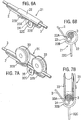
- FIG. 6A and 6B A second embodiment is shown in Figures 6A and 6B which does not use wheels.
- the traveller 21 is formed by a single curved cylindrical plate 22 formed in a curve extending around the safety line 3 to form a generally cylindrical tube broken by a slot 23 formed between an inner gate 22A formed by an inwardly projecting end of the plate 22 and an outer gate 22B formed by an outwardly projecting end of the plate 22.
- the geometry of the inner and outer gates 22A and 22B and the slot 23 is the same as the geometry of the inner and outer gates 11A and 11B and slot 11 of the first embodiment so that the traveller 21 can move along a safety line 3 and traverse supports 2 without releasing the safety line 3.
- the traveller 21 includes an attachment section 22C formed by an outwardly projecting section of the plate 22 with an aperture 24 allowing a carabineer or similar attachment device to be secured to the traveller 21 by passing though the aperture 24.
- the plate is divided into three sections along its length, the end sections extending around the safety line 3 to form the outer gate 22B and the central section extending radially from the safety line 3 to form the attachment section 22C.
- the traveller 21 operates similarly to the traveller 1 as explained above.
- the first side plate 5 is curved round to provide a part of the securing section 9 and has ribs 16 to increase its rigidity in order to prevent the first side plate 5 bending under load and allowing the slot 11 to open out.
- the first side plate 5 and part of the securing section 9 are formed from a single plate and the engagement section 7 and the part of the second side plate 6 including the outer gate 11B are formed from a second single plate by bending and the remainder of the second side plate 6 including the inner gate 11A is formed from a third plate.
- FIGS 7A and 7B show the traveller 31 formed by a single plate 32 supporting a pair of wheels 33 arranged in tandem.
- the wheels 33 are formed so that their rims define the channel receiving the safety line 3 and the outer rim 33A of the wheel 33 projects inwardly to form the inner gate 11A.
- An end of the plate 22 is bent around the safety line 3 to form the outer gate 32B so that the rims 33A of the wheels 33 and the outer gate 32B formed by the plate 32 define a slot 34 between them.
- the inner and outer gates 33A and 32B and the slot 34 are arranged similarly to the inner and outer gates 11A and 11B and slot 11 of the first embodiment so that the traveller 31 can move along the safety line 3 and pass over the support 2 without releasing the safety line 3 from the traveller 31.
- a downwardly projecting section of the plate 32 extends radially from the safety line 3 to form an attachment element 32C having an aperture 35 allowing a safety lanyard to be attached to the traveller 31 using a carabineer or similar attachment device passing through the aperture 35.
- the plate 32 is arranged to have two end sections adjacent the wheels 33 and extending around the safety line 3 to form the outer gates 32B and a central section extending radially to the safety line 3 to form the attachment section 32C.
- the safety line 3 and/or support 2 are retained within a passage defined by rigid components of the traveller so that the traveller can only be removed from the safety line 3 by passing the traveller over the end of the safety line 3 or by providing special supports 2 incorporating an openable section.
- Such openable arrangements allowing travellers to be removed and detached from safety lines are well known in the art.
- lockable opening mechanism could be incorporated into the traveller to allow the traveller to be attached to and removed from the safety line at any point.
- Such lockable opening devices are well known in the art.
- FIG. 8A to 8E A fourth embodiment of the invention is shown in Figures 8A to 8E .
- the traveller 41 of the fourth embodiment includes a pair of rollers 42 each having an outer rim forming the inner gate 42A similarly to the rollers 33 of the third embodiment. Further, the traveller 41 includes a further pair of rollers 43 having outer rims which define an outer gate 43B. Respective opposed ones of the first rollers 42 and second rollers 43 are arranged to rotate about parallel axes so that their outer rims forming the inner gate 42A and outer gate 43B define a slot 44 between them.
- the inner gate 42A, outer gate 34B and slot 44 are arranged similarly to the inner gate 11A, outer gate 11B and slot 11 according to the first embodiment to allow the traveller 41 to move along the safety line 3 and traverse supports 2 without being released from the safety line 3.
- the traveller 41 has a downwardly extending section forming an attachment element 45 with an aperture 46 allowing a safety lanyard to be attached to the traveller by passing a carabineer or similar attachment device through the aperture 46.
- rollers 42 and 43 are pivotally connected for relative movement about an axis 47 between a first retaining position and a second releasing position.
- the traveller 41 is shown in the first retaining position in Figures 8A to 8D and in the second releasing position in Figure 8E .
- the axes of rotation of the rollers 42 and 43 are parallel and the slot 44 is narrower than the diameter of the safety line 3 so that the traveller 41 cannot be released from the safety line 3.
- the slot 44 is widened so that the safety line 3 can pass through it. Accordingly, when the traveller 41 is in the second releasing position the traveller can be moved from or attached to a safety line 3.
- the attachment element 45 is formed by two parallel extensions with respective apertures 46.
- a first one of the extensions is rigidly attached to the first pair of rollers 42 while the second section is rigidly attached to the second pair of rollers 43.
- the apertures 46 are arranged so that they are in line allowing a carabineer or other safety harness to be inserted only when the traveller is in the first retaining position. Further, the apertures 46 are sized so that when a carabineer or similar safety device is located passing though both of the apertures 46 it is not possible to move the rollers 42 and 43 from the first retaining position to the second releasing position. This arrangement of interlocking prevents accidental release of the traveller 41 from the safety line 3 while in use.
- pairs of opposed rollers to define the inner gate, outer gate and slot according to the fourth embodiment does not require the use of a lockable opening mechanism to release the traveller from the safety line.
- the roller arrangement according to the fourth embodiment could be used with a rigid traveller arrangement if desired.
Landscapes
- Health & Medical Sciences (AREA)
- General Health & Medical Sciences (AREA)
- Business, Economics & Management (AREA)
- Emergency Management (AREA)
- Emergency Lowering Means (AREA)
Claims (7)
- Träger (2) für eine Sicherheitsleine in einem Absturzsicherungssystem, der einen Halteabschnitt (12), der sich zum Halten einer Sicherheitsleine (3) eignet, und ein Befestigungsmittel (14) zum Befestigen des Trägers (2) an einer Struktur umfasst, wobei der Halteabschnitt (12) und das Befestigungsmittel (14) über einen Arm (13) verbunden sind, wobei der Arm einen tangentialen Abschnitt (13B) aufweist, der schmaler ist als die Sicherheitsleine (3) und im Wesentlichen tangential bezogen auf eine Sicherheitsleine verläuft, die im Halteabschnitt (12) gehalten ist, dadurch gekennzeichnet, dass der tangentiale Abschnitt (13B) eine ebene Platte ist und der Arm (13) einen ersten radialen Abschnitt (13A) aufweist, der von dem Halteabschnitt (12) aus vertikal nach unten verläuft, wobei der tangentiale Abschnitt (13B) vom unteren Ende des ersten radialen Abschnitts (13A) zu einem dritten Abschnitt (13C) verläuft, der den tangentialen Abschnitt (13B) mit dem Befestigungsmittel (14) verbindet.
- Träger nach Anspruch 1, bei dem der Halteabschnitt (12) eine zylindrische Röhre ist.
- Träger nach Anspruch 1 oder Anspruch 2, bei dem der tangentiale Abschnitt (13B) einen Abstand zum Halteabschnitt (12) aufweist.
- Träger nach einem der vorhergehenden Ansprüche, bei dem das Befestigungsmittel (14), der tangentiale Abschnitt (13B) und der Halteabschnitt (12) einteilig aus einer einzigen Platte geformt sind.
- Träger nach einem der vorhergehenden Ansprüche, wobei das Befestigungsmittel (14) über der Sicherheitsleine (3) platziert ist.
- Träger nach einem der vorhergehenden Ansprüche, wobei der tangentiale Abschnitt (13B) bezogen auf das Befestigungsmittel (14) geneigt ist.
- Träger (2) nach einem der vorhergehenden Ansprüche in Kombination mit einem Läufer (1), wobei der Läufer (1) einen Körper mit einem Durchgang (10) durch ihn hindurch, einen Schlitz (11), der schmaler ist als die Sicherheitsleine (3) und den Durchgang (10) mit der Außenseite des Körpers verbindet, und ein Lastelement (7) umfasst, das sich dafür eignet, den Läufer an Fallschutzausrüstung anzubringen, wobei der Schlitz (11) zwischen einem inneren Durchlass (11A) und einem äußeren Durchlass (11b) mit jeweils gegenüberliegenden Flächen ausgebildet ist, die den Schlitz (11) dazwischen definieren, wobei der innere Durchlass und der äußere Durchlass (11A, 11B) derart angeordnet sind, dass, wenn der Läufer (1) an dem Träger (2) innerhalb des Durchgangs (10) montiert ist, der tangentiale Abschnitt (13B) des Arms durch den Schlitz (11) verlaufen kann.
Applications Claiming Priority (3)
| Application Number | Priority Date | Filing Date | Title |
|---|---|---|---|
| GB0228524A GB2395976A (en) | 2002-12-06 | 2002-12-06 | Safety line traveller and support |
| PCT/GB2003/005313 WO2004052465A1 (en) | 2002-12-06 | 2003-12-05 | Safety line traveller and support |
| EP03778594.6A EP1567229B1 (de) | 2002-12-06 | 2003-12-05 | Läufer und stütze für sicherheitsleine |
Related Parent Applications (3)
| Application Number | Title | Priority Date | Filing Date |
|---|---|---|---|
| EP03778594.6 Division | 2003-12-05 | ||
| EP03778594.6A Division-Into EP1567229B1 (de) | 2002-12-06 | 2003-12-05 | Läufer und stütze für sicherheitsleine |
| EP03778594.6A Division EP1567229B1 (de) | 2002-12-06 | 2003-12-05 | Läufer und stütze für sicherheitsleine |
Publications (2)
| Publication Number | Publication Date |
|---|---|
| EP2269696A1 EP2269696A1 (de) | 2011-01-05 |
| EP2269696B1 true EP2269696B1 (de) | 2018-07-25 |
Family
ID=9949225
Family Applications (2)
| Application Number | Title | Priority Date | Filing Date |
|---|---|---|---|
| EP03778594.6A Expired - Lifetime EP1567229B1 (de) | 2002-12-06 | 2003-12-05 | Läufer und stütze für sicherheitsleine |
| EP10184414.0A Expired - Lifetime EP2269696B1 (de) | 2002-12-06 | 2003-12-05 | Läufer und stütze für sicherheitsleine |
Family Applications Before (1)
| Application Number | Title | Priority Date | Filing Date |
|---|---|---|---|
| EP03778594.6A Expired - Lifetime EP1567229B1 (de) | 2002-12-06 | 2003-12-05 | Läufer und stütze für sicherheitsleine |
Country Status (7)
| Country | Link |
|---|---|
| US (2) | US20060124391A1 (de) |
| EP (2) | EP1567229B1 (de) |
| AU (2) | AU2003285595A1 (de) |
| CA (2) | CA2822848C (de) |
| ES (1) | ES2534219T3 (de) |
| GB (1) | GB2395976A (de) |
| WO (1) | WO2004052465A1 (de) |
Families Citing this family (14)
| Publication number | Priority date | Publication date | Assignee | Title |
|---|---|---|---|---|
| GB2395976A (en) * | 2002-12-06 | 2004-06-09 | Latchways Plc | Safety line traveller and support |
| EP2081652B1 (de) * | 2006-10-27 | 2016-12-14 | Edelrid GmbH & Co. KG | Sicherungseinrichtung |
| DE102008011173A1 (de) * | 2008-02-26 | 2009-09-10 | Bornack Gmbh & Co. Kg | Sicherungseinrichtung |
| DE202008004254U1 (de) * | 2008-03-28 | 2009-08-13 | Sperian Fall Protection Deutschland Gmbh & Co. Kg | Zwischenhalter für das Sicherungsseil eines Überkopf-Seilsystems einer Absturzsicherung |
| GB2463631A (en) * | 2008-04-28 | 2010-03-24 | Latchways Plc | Safety line traveller and support |
| GB2459654B (en) * | 2008-04-28 | 2012-08-08 | Latchways Plc | Safety line traveller |
| GB0812369D0 (en) * | 2008-07-05 | 2008-08-13 | Hy Safe Ind Products Ltd | Saftey apparatus |
| DE102008033431B4 (de) * | 2008-07-16 | 2010-03-04 | Faszinatour Touristik - Training - Event Gmbh | Anschlagelement für eine Sicherungseinrichtung |
| CH700884A2 (de) * | 2009-04-22 | 2010-10-29 | Repapress Ag | Sicherheitseinrichtung für einen Seilgarten. |
| GB0915277D0 (en) * | 2009-09-02 | 2009-10-07 | Latchways Plc | Safety line traveller |
| CH704409B1 (fr) * | 2011-01-31 | 2015-09-15 | Kanopeo Gmbh | Poulie pour système de ligne d'assurage continue. |
| NL1039209C2 (nl) * | 2011-12-02 | 2013-06-06 | Xsplatforms B V | Loper voor geleiding langs een geleidingskabel van een verankeringsinrichting. |
| DE102017004948A1 (de) * | 2017-05-23 | 2018-11-29 | Spanset Inter Ag | Seilhalterung und Laufelement |
| JP6967218B2 (ja) * | 2017-06-26 | 2021-11-17 | 藤井電工株式会社 | 安全器 |
Family Cites Families (26)
| Publication number | Priority date | Publication date | Assignee | Title |
|---|---|---|---|---|
| US304730A (en) * | 1884-09-09 | Fire-escape | ||
| US857924A (en) * | 1906-05-07 | 1907-06-25 | Bert C Crandall | Conveying apparatus. |
| US2395976A (en) * | 1941-06-20 | 1946-03-05 | Standard Oil Co | Tractor fuel and process of making same |
| US2500805A (en) * | 1945-03-20 | 1950-03-14 | Costello Edward | Exercising device for horses |
| US3601348A (en) * | 1969-09-17 | 1971-08-24 | George E Gonsalves | Rail support for overhead conveyors |
| US3648664A (en) * | 1970-07-02 | 1972-03-14 | William M Nunley | Animal tethering apparatus and the like |
| US4667625A (en) * | 1985-11-21 | 1987-05-26 | Malone Garry B | Dog run apparatus having shock absorbing capability |
| US4862883A (en) * | 1988-04-21 | 1989-09-05 | Yosef Freeland | Interlocking intramedullary nail |
| GB9011370D0 (en) * | 1990-05-22 | 1990-07-11 | Barrow Hepburn Sala Ltd | Energy-absorbing bracket |
| GB9110900D0 (en) * | 1991-05-21 | 1991-07-10 | Barrow Hepburn Sala Ltd | Safety apparatus |
| FR2700799B1 (fr) * | 1993-01-22 | 1995-03-24 | Protecta International | Dispositif d'ancrage mobile permettant le déplacement en toute sécurité selon un axe horizontal. |
| US5437246A (en) * | 1994-01-14 | 1995-08-01 | Noles; Larry J. | Corner turning free-run animal trolley system |
| GB2293193A (en) * | 1994-09-19 | 1996-03-20 | Latchways Ltd | Fall arrest device |
| US5979599A (en) * | 1996-12-17 | 1999-11-09 | Noles; Larry J. | Track transport system, track-support bracket, and track-traveling apparatus |
| GB2351057A (en) * | 1999-06-14 | 2000-12-20 | Latchways Plc | Removable load transfer device for height safety apparatus |
| US6488118B1 (en) * | 2000-04-27 | 2002-12-03 | John A. Corriveau | Fall arrest bypass device and method for using same |
| US6408798B1 (en) * | 2001-02-02 | 2002-06-25 | Larry Van Damme | Tangle resistance pet tie device |
| US6488188B2 (en) * | 2001-04-02 | 2002-12-03 | Jack A. Fleischli | Combination backpack and protective body heat retaining pod |
| GB2375366A (en) * | 2001-05-11 | 2002-11-13 | Latchways Plc | Safety line and shuttle arrangement |
| DE60208702T2 (de) * | 2001-05-11 | 2006-08-24 | Latchways Plc, Devizes | Läufer und stütze für sicherheitsleine |
| GB2395976A (en) * | 2002-12-06 | 2004-06-09 | Latchways Plc | Safety line traveller and support |
| US6886498B1 (en) * | 2003-10-28 | 2005-05-03 | Francis A. Rochette | Animal leash and running device |
| US7040255B1 (en) * | 2004-07-27 | 2006-05-09 | Anderson Michael D | Pet restraint |
| US7721655B1 (en) * | 2007-09-19 | 2010-05-25 | Riggie Donald E | Transport system |
| DE202008004254U1 (de) * | 2008-03-28 | 2009-08-13 | Sperian Fall Protection Deutschland Gmbh & Co. Kg | Zwischenhalter für das Sicherungsseil eines Überkopf-Seilsystems einer Absturzsicherung |
| GB2459654B (en) * | 2008-04-28 | 2012-08-08 | Latchways Plc | Safety line traveller |
-
2002
- 2002-12-06 GB GB0228524A patent/GB2395976A/en not_active Withdrawn
-
2003
- 2003-12-05 US US10/537,424 patent/US20060124391A1/en not_active Abandoned
- 2003-12-05 EP EP03778594.6A patent/EP1567229B1/de not_active Expired - Lifetime
- 2003-12-05 CA CA2822848A patent/CA2822848C/en not_active Expired - Fee Related
- 2003-12-05 WO PCT/GB2003/005313 patent/WO2004052465A1/en not_active Ceased
- 2003-12-05 EP EP10184414.0A patent/EP2269696B1/de not_active Expired - Lifetime
- 2003-12-05 AU AU2003285595A patent/AU2003285595A1/en not_active Abandoned
- 2003-12-05 ES ES03778594.6T patent/ES2534219T3/es not_active Expired - Lifetime
- 2003-12-05 CA CA2508265A patent/CA2508265C/en not_active Expired - Fee Related
-
2011
- 2011-01-20 AU AU2011200220A patent/AU2011200220B2/en not_active Ceased
-
2013
- 2013-09-11 US US14/024,111 patent/US20140008148A1/en not_active Abandoned
Non-Patent Citations (1)
| Title |
|---|
| None * |
Also Published As
| Publication number | Publication date |
|---|---|
| US20140008148A1 (en) | 2014-01-09 |
| AU2003285595A1 (en) | 2004-06-30 |
| CA2822848A1 (en) | 2004-06-24 |
| CA2508265C (en) | 2014-07-15 |
| CA2508265A1 (en) | 2004-06-24 |
| GB2395976A (en) | 2004-06-09 |
| AU2011200220A1 (en) | 2011-02-10 |
| ES2534219T3 (es) | 2015-04-20 |
| AU2011200220B2 (en) | 2011-12-01 |
| GB0228524D0 (en) | 2003-01-15 |
| WO2004052465A1 (en) | 2004-06-24 |
| CA2822848C (en) | 2016-10-11 |
| EP2269696A1 (de) | 2011-01-05 |
| EP1567229B1 (de) | 2015-01-07 |
| EP1567229A1 (de) | 2005-08-31 |
| US20060124391A1 (en) | 2006-06-15 |
Similar Documents
| Publication | Publication Date | Title |
|---|---|---|
| US20140008148A1 (en) | Safety Line Traveller and Support | |
| US9033103B2 (en) | Safety line traveller and support | |
| US6488118B1 (en) | Fall arrest bypass device and method for using same | |
| US7603952B2 (en) | Trolley and rail apparatus for use in fall protection and similar applications | |
| EP0961637A1 (de) | Abstürzsicherungsvorrichtung | |
| US20250073509A1 (en) | Horizontal lifeline shuttle apparatus | |
| EP4149637B1 (de) | Höhensicherheitswagen und modulares starres schienensystem | |
| AU2002307930B2 (en) | Safety line traveller and support | |
| AU2014202964A1 (en) | Safety LineTraveller and Support | |
| AU2002307930A1 (en) | Safety line traveller and support | |
| US8522919B2 (en) | Two-way locking device for height safety apparatus | |
| CN214971712U (zh) | 一种生命线系统 | |
| WO2016118115A1 (en) | Monorail system |
Legal Events
| Date | Code | Title | Description |
|---|---|---|---|
| PUAI | Public reference made under article 153(3) epc to a published international application that has entered the european phase |
Free format text: ORIGINAL CODE: 0009012 |
|
| AC | Divisional application: reference to earlier application |
Ref document number: 1567229 Country of ref document: EP Kind code of ref document: P |
|
| AK | Designated contracting states |
Kind code of ref document: A1 Designated state(s): AT BE BG CH CY CZ DE DK EE ES FI FR GB GR HU IE IT LI LU MC NL PT RO SE SI SK TR |
|
| 17P | Request for examination filed |
Effective date: 20110705 |
|
| 17Q | First examination report despatched |
Effective date: 20170713 |
|
| REG | Reference to a national code |
Ref country code: DE Ref legal event code: R079 Ref document number: 60351355 Country of ref document: DE Free format text: PREVIOUS MAIN CLASS: A62B0035040000 Ipc: A62B0035000000 |
|
| GRAP | Despatch of communication of intention to grant a patent |
Free format text: ORIGINAL CODE: EPIDOSNIGR1 |
|
| RIC1 | Information provided on ipc code assigned before grant |
Ipc: A62B 35/00 20060101AFI20180207BHEP |
|
| INTG | Intention to grant announced |
Effective date: 20180301 |
|
| GRAS | Grant fee paid |
Free format text: ORIGINAL CODE: EPIDOSNIGR3 |
|
| GRAA | (expected) grant |
Free format text: ORIGINAL CODE: 0009210 |
|
| AC | Divisional application: reference to earlier application |
Ref document number: 1567229 Country of ref document: EP Kind code of ref document: P |
|
| AK | Designated contracting states |
Kind code of ref document: B1 Designated state(s): AT BE BG CH CY CZ DE DK EE ES FI FR GB GR HU IE IT LI LU MC NL PT RO SE SI SK TR |
|
| REG | Reference to a national code |
Ref country code: GB Ref legal event code: FG4D |
|
| REG | Reference to a national code |
Ref country code: CH Ref legal event code: EP |
|
| REG | Reference to a national code |
Ref country code: AT Ref legal event code: REF Ref document number: 1021128 Country of ref document: AT Kind code of ref document: T Effective date: 20180815 |
|
| REG | Reference to a national code |
Ref country code: DE Ref legal event code: R096 Ref document number: 60351355 Country of ref document: DE |
|
| REG | Reference to a national code |
Ref country code: IE Ref legal event code: FG4D |
|
| REG | Reference to a national code |
Ref country code: NL Ref legal event code: FP |
|
| REG | Reference to a national code |
Ref country code: AT Ref legal event code: MK05 Ref document number: 1021128 Country of ref document: AT Kind code of ref document: T Effective date: 20180725 |
|
| PG25 | Lapsed in a contracting state [announced via postgrant information from national office to epo] |
Ref country code: SE Free format text: LAPSE BECAUSE OF FAILURE TO SUBMIT A TRANSLATION OF THE DESCRIPTION OR TO PAY THE FEE WITHIN THE PRESCRIBED TIME-LIMIT Effective date: 20180725 Ref country code: AT Free format text: LAPSE BECAUSE OF FAILURE TO SUBMIT A TRANSLATION OF THE DESCRIPTION OR TO PAY THE FEE WITHIN THE PRESCRIBED TIME-LIMIT Effective date: 20180725 Ref country code: BG Free format text: LAPSE BECAUSE OF FAILURE TO SUBMIT A TRANSLATION OF THE DESCRIPTION OR TO PAY THE FEE WITHIN THE PRESCRIBED TIME-LIMIT Effective date: 20181025 Ref country code: GR Free format text: LAPSE BECAUSE OF FAILURE TO SUBMIT A TRANSLATION OF THE DESCRIPTION OR TO PAY THE FEE WITHIN THE PRESCRIBED TIME-LIMIT Effective date: 20181026 Ref country code: FI Free format text: LAPSE BECAUSE OF FAILURE TO SUBMIT A TRANSLATION OF THE DESCRIPTION OR TO PAY THE FEE WITHIN THE PRESCRIBED TIME-LIMIT Effective date: 20180725 |
|
| PG25 | Lapsed in a contracting state [announced via postgrant information from national office to epo] |
Ref country code: ES Free format text: LAPSE BECAUSE OF FAILURE TO SUBMIT A TRANSLATION OF THE DESCRIPTION OR TO PAY THE FEE WITHIN THE PRESCRIBED TIME-LIMIT Effective date: 20180725 |
|
| REG | Reference to a national code |
Ref country code: DE Ref legal event code: R097 Ref document number: 60351355 Country of ref document: DE |
|
| PG25 | Lapsed in a contracting state [announced via postgrant information from national office to epo] |
Ref country code: IT Free format text: LAPSE BECAUSE OF FAILURE TO SUBMIT A TRANSLATION OF THE DESCRIPTION OR TO PAY THE FEE WITHIN THE PRESCRIBED TIME-LIMIT Effective date: 20180725 Ref country code: EE Free format text: LAPSE BECAUSE OF FAILURE TO SUBMIT A TRANSLATION OF THE DESCRIPTION OR TO PAY THE FEE WITHIN THE PRESCRIBED TIME-LIMIT Effective date: 20180725 Ref country code: RO Free format text: LAPSE BECAUSE OF FAILURE TO SUBMIT A TRANSLATION OF THE DESCRIPTION OR TO PAY THE FEE WITHIN THE PRESCRIBED TIME-LIMIT Effective date: 20180725 Ref country code: CZ Free format text: LAPSE BECAUSE OF FAILURE TO SUBMIT A TRANSLATION OF THE DESCRIPTION OR TO PAY THE FEE WITHIN THE PRESCRIBED TIME-LIMIT Effective date: 20180725 |
|
| PG25 | Lapsed in a contracting state [announced via postgrant information from national office to epo] |
Ref country code: SK Free format text: LAPSE BECAUSE OF FAILURE TO SUBMIT A TRANSLATION OF THE DESCRIPTION OR TO PAY THE FEE WITHIN THE PRESCRIBED TIME-LIMIT Effective date: 20180725 Ref country code: DK Free format text: LAPSE BECAUSE OF FAILURE TO SUBMIT A TRANSLATION OF THE DESCRIPTION OR TO PAY THE FEE WITHIN THE PRESCRIBED TIME-LIMIT Effective date: 20180725 |
|
| PLBE | No opposition filed within time limit |
Free format text: ORIGINAL CODE: 0009261 |
|
| STAA | Information on the status of an ep patent application or granted ep patent |
Free format text: STATUS: NO OPPOSITION FILED WITHIN TIME LIMIT |
|
| 26N | No opposition filed |
Effective date: 20190426 |
|
| REG | Reference to a national code |
Ref country code: CH Ref legal event code: PL |
|
| PG25 | Lapsed in a contracting state [announced via postgrant information from national office to epo] |
Ref country code: MC Free format text: LAPSE BECAUSE OF FAILURE TO SUBMIT A TRANSLATION OF THE DESCRIPTION OR TO PAY THE FEE WITHIN THE PRESCRIBED TIME-LIMIT Effective date: 20180725 Ref country code: SI Free format text: LAPSE BECAUSE OF FAILURE TO SUBMIT A TRANSLATION OF THE DESCRIPTION OR TO PAY THE FEE WITHIN THE PRESCRIBED TIME-LIMIT Effective date: 20180725 Ref country code: LU Free format text: LAPSE BECAUSE OF NON-PAYMENT OF DUE FEES Effective date: 20181205 |
|
| REG | Reference to a national code |
Ref country code: IE Ref legal event code: MM4A |
|
| PG25 | Lapsed in a contracting state [announced via postgrant information from national office to epo] |
Ref country code: IE Free format text: LAPSE BECAUSE OF NON-PAYMENT OF DUE FEES Effective date: 20181205 |
|
| PG25 | Lapsed in a contracting state [announced via postgrant information from national office to epo] |
Ref country code: CH Free format text: LAPSE BECAUSE OF NON-PAYMENT OF DUE FEES Effective date: 20181231 Ref country code: LI Free format text: LAPSE BECAUSE OF NON-PAYMENT OF DUE FEES Effective date: 20181231 |
|
| PGFP | Annual fee paid to national office [announced via postgrant information from national office to epo] |
Ref country code: DE Payment date: 20191119 Year of fee payment: 17 Ref country code: NL Payment date: 20191212 Year of fee payment: 17 |
|
| PGFP | Annual fee paid to national office [announced via postgrant information from national office to epo] |
Ref country code: FR Payment date: 20191115 Year of fee payment: 17 Ref country code: BE Payment date: 20191119 Year of fee payment: 17 |
|
| PG25 | Lapsed in a contracting state [announced via postgrant information from national office to epo] |
Ref country code: TR Free format text: LAPSE BECAUSE OF FAILURE TO SUBMIT A TRANSLATION OF THE DESCRIPTION OR TO PAY THE FEE WITHIN THE PRESCRIBED TIME-LIMIT Effective date: 20180725 |
|
| PG25 | Lapsed in a contracting state [announced via postgrant information from national office to epo] |
Ref country code: PT Free format text: LAPSE BECAUSE OF FAILURE TO SUBMIT A TRANSLATION OF THE DESCRIPTION OR TO PAY THE FEE WITHIN THE PRESCRIBED TIME-LIMIT Effective date: 20180725 |
|
| PG25 | Lapsed in a contracting state [announced via postgrant information from national office to epo] |
Ref country code: HU Free format text: LAPSE BECAUSE OF FAILURE TO SUBMIT A TRANSLATION OF THE DESCRIPTION OR TO PAY THE FEE WITHIN THE PRESCRIBED TIME-LIMIT; INVALID AB INITIO Effective date: 20031205 Ref country code: CY Free format text: LAPSE BECAUSE OF FAILURE TO SUBMIT A TRANSLATION OF THE DESCRIPTION OR TO PAY THE FEE WITHIN THE PRESCRIBED TIME-LIMIT Effective date: 20180725 |
|
| REG | Reference to a national code |
Ref country code: DE Ref legal event code: R119 Ref document number: 60351355 Country of ref document: DE |
|
| REG | Reference to a national code |
Ref country code: NL Ref legal event code: MM Effective date: 20210101 |
|
| REG | Reference to a national code |
Ref country code: BE Ref legal event code: MM Effective date: 20201231 |
|
| PG25 | Lapsed in a contracting state [announced via postgrant information from national office to epo] |
Ref country code: NL Free format text: LAPSE BECAUSE OF NON-PAYMENT OF DUE FEES Effective date: 20210101 |
|
| PG25 | Lapsed in a contracting state [announced via postgrant information from national office to epo] |
Ref country code: FR Free format text: LAPSE BECAUSE OF NON-PAYMENT OF DUE FEES Effective date: 20201231 |
|
| PG25 | Lapsed in a contracting state [announced via postgrant information from national office to epo] |
Ref country code: DE Free format text: LAPSE BECAUSE OF NON-PAYMENT OF DUE FEES Effective date: 20210701 |
|
| PG25 | Lapsed in a contracting state [announced via postgrant information from national office to epo] |
Ref country code: BE Free format text: LAPSE BECAUSE OF NON-PAYMENT OF DUE FEES Effective date: 20201231 |
|
| PGFP | Annual fee paid to national office [announced via postgrant information from national office to epo] |
Ref country code: GB Payment date: 20221013 Year of fee payment: 20 |
|
| P01 | Opt-out of the competence of the unified patent court (upc) registered |
Effective date: 20230626 |
|
| REG | Reference to a national code |
Ref country code: GB Ref legal event code: PE20 Expiry date: 20231204 |
|
| PG25 | Lapsed in a contracting state [announced via postgrant information from national office to epo] |
Ref country code: GB Free format text: LAPSE BECAUSE OF EXPIRATION OF PROTECTION Effective date: 20231204 |
|
| PG25 | Lapsed in a contracting state [announced via postgrant information from national office to epo] |
Ref country code: GB Free format text: LAPSE BECAUSE OF EXPIRATION OF PROTECTION Effective date: 20231204 |