EP2269447A2 - Eingrenzungsbehälter - Google Patents
Eingrenzungsbehälter Download PDFInfo
- Publication number
- EP2269447A2 EP2269447A2 EP10166700A EP10166700A EP2269447A2 EP 2269447 A2 EP2269447 A2 EP 2269447A2 EP 10166700 A EP10166700 A EP 10166700A EP 10166700 A EP10166700 A EP 10166700A EP 2269447 A2 EP2269447 A2 EP 2269447A2
- Authority
- EP
- European Patent Office
- Prior art keywords
- confinement
- confinement enclosure
- moulded housing
- piece moulded
- enclosure
- Prior art date
- Legal status (The legal status is an assumption and is not a legal conclusion. Google has not performed a legal analysis and makes no representation as to the accuracy of the status listed.)
- Granted
Links
- 238000000465 moulding Methods 0.000 claims abstract description 12
- 238000004519 manufacturing process Methods 0.000 claims abstract description 8
- 239000000463 material Substances 0.000 claims description 30
- 230000000295 complement effect Effects 0.000 claims description 3
- 241000238557 Decapoda Species 0.000 abstract description 9
- 241000251468 Actinopterygii Species 0.000 abstract description 3
- 241000238424 Crustacea Species 0.000 abstract description 2
- 238000001175 rotational moulding Methods 0.000 description 4
- 238000007689 inspection Methods 0.000 description 3
- 229910000831 Steel Inorganic materials 0.000 description 2
- 238000005299 abrasion Methods 0.000 description 2
- 230000000712 assembly Effects 0.000 description 2
- 238000000429 assembly Methods 0.000 description 2
- 238000000034 method Methods 0.000 description 2
- 239000004810 polytetrafluoroethylene Substances 0.000 description 2
- 229920001343 polytetrafluoroethylene Polymers 0.000 description 2
- 239000010959 steel Substances 0.000 description 2
- 235000001543 Corylus americana Nutrition 0.000 description 1
- 240000007582 Corylus avellana Species 0.000 description 1
- 235000007466 Corylus avellana Nutrition 0.000 description 1
- 229910001209 Low-carbon steel Inorganic materials 0.000 description 1
- 241000124033 Salix Species 0.000 description 1
- 238000005553 drilling Methods 0.000 description 1
- 238000002347 injection Methods 0.000 description 1
- 239000007924 injection Substances 0.000 description 1
- JEIPFZHSYJVQDO-UHFFFAOYSA-N iron(III) oxide Inorganic materials O=[Fe]O[Fe]=O JEIPFZHSYJVQDO-UHFFFAOYSA-N 0.000 description 1
- 229920001179 medium density polyethylene Polymers 0.000 description 1
- 239000004701 medium-density polyethylene Substances 0.000 description 1
- 239000002184 metal Substances 0.000 description 1
- 239000004033 plastic Substances 0.000 description 1
- 229920003023 plastic Polymers 0.000 description 1
- 229920000642 polymer Polymers 0.000 description 1
- 239000000843 powder Substances 0.000 description 1
- 239000012858 resilient material Substances 0.000 description 1
- 235000015170 shellfish Nutrition 0.000 description 1
- 239000007787 solid Substances 0.000 description 1
- 230000000007 visual effect Effects 0.000 description 1
- XLYOFNOQVPJJNP-UHFFFAOYSA-N water Substances O XLYOFNOQVPJJNP-UHFFFAOYSA-N 0.000 description 1
- 239000002023 wood Substances 0.000 description 1
Images


Classifications
-
- A—HUMAN NECESSITIES
- A01—AGRICULTURE; FORESTRY; ANIMAL HUSBANDRY; HUNTING; TRAPPING; FISHING
- A01K—ANIMAL HUSBANDRY; AVICULTURE; APICULTURE; PISCICULTURE; FISHING; REARING OR BREEDING ANIMALS, NOT OTHERWISE PROVIDED FOR; NEW BREEDS OF ANIMALS
- A01K69/00—Stationary catching devices
- A01K69/06—Traps
- A01K69/08—Rigid traps, e.g. lobster pots
Definitions
- the present invention relates to a confinement enclosure for a marine entrapment assembly, to a marine entrapment assembly for capturing marine creatures (such as crustaceans (eg crabs and lobsters) and fish) comprising the confinement enclosure and to a moulding tool comprising a mould cavity shaped to manufacture the confinement enclosure.
- marine creatures such as crustaceans (eg crabs and lobsters) and fish
- a conventional entrapment assembly for capturing crabs and lobsters comprises a framework to which is attached meshing.
- the framework is made from plastic, steel, wire or a more traditional material such as wood, willow or hazel and may comprise bars, rods, struts or tubes.
- One such assembly is described in GB-A-2350042 .
- Another conventional marine entrapment assembly comprises a number of injection moulded panels tied together and provided with cut out holes.
- the present invention seeks to address certain drawbacks of marine entrapment assemblies by exploiting a confinement enclosure with a one-piece moulded housing.
- the present invention provides a confinement enclosure for a marine entrapment assembly comprising (or consisting essentially of or consisting of):
- the confinement enclosure offers improvements inter alia in robustness and strength and is straightforward to manufacture.
- the profile of the one-piece moulded housing may be substantially semipolygonal.
- the profile of the one-piece moulded housing may be substantially semi-hexagonal, semi-octagonal or semi-dodecagonal.
- the one-piece moulded housing is semi-octagonal.
- the one-piece moulded housing may be box-like (eg substantially cuboidal or cubic).
- the one-piece moulded housing is typically elongate.
- the one-piece moulded housing may resemble a barrel vault.
- the (or each) entrance window may be suitably sized to exclude (if desired) undesirably large marine creatures.
- the one or more entrance windows for marine creatures include an entrance window near to the proximal end.
- the one or more access windows include an access window near to the distal end.
- the access windows may be used to access the confinement space for retrieving a catch or for attaching reticulated material.
- Each of the distal end and proximal end may be independently closed, perforated or open.
- the proximal end is perforated.
- the distal end may be open or perforated.
- the ceiling may be substantially planar, arched (eg substantially semi-cylindrical or hemispherical) or vaulted.
- the ceiling is at least partially (eg substantially fully or fully) perforated (eg substantially uniformly perforated).
- the ceiling may include an entrance window for marine creatures.
- the entrance window may be near to the proximal end.
- the floor may be substantially planar.
- the floor is at least partially (eg substantially fully or fully) perforated (eg substantially uniformly perforated).
- the one piece moulded housing is equipped with one or more side windows.
- the one piece moulded housing is equipped with a plurality of side windows.
- Each side window may be independently closed, perforated or open.
- each side window is recessed.
- each side window is recessed with a substantially orthogonal return surface.
- the substantially orthogonal return surface may extend around a part or the whole of the perimeter of the side window.
- the plurality of side windows includes one or more (preferably more than one) entrance windows for marine creatures.
- the plurality of side windows includes an entrance window for marine creatures near to the proximal end.
- the plurality of side windows includes a first entrance window for marine creatures in the first side wall non-diametrically opposed to a second entrance window for marine creatures in the second side wall.
- the plurality of side windows includes one or more (preferably more than one) access window.
- the plurality of side windows includes an access window near to the distal end.
- the distal end is open and includes an access window or is openable to include an access window.
- the openable distal end may be opened (eg by cutting) to create an access window.
- the confinement enclosure further comprises:
- the profile of the door typically matches the profile of the access window.
- the access window may be bound by a door mounting (eg arch).
- the door is perforated.
- the door is selectively pivotal, rotational or slidable between the closed position located in the access window and the open position dislocated from the access window.
- the door may be separate to or integral with the one-piece moulded housing.
- the one-piece moulded housing and door may be one-piece moulded.
- the door may be coupled (eg tied) or joined to the one-piece moulded housing (eg to the floor of the one-piece moulded housing).
- the door may be foldably joined to the one-piece moulded housing. This may be facilitated by a weakened (eg thinned or scored) portion of the one-piece mould between the door and one-piece moulded housing.
- the confinement enclosure may further comprise a clasp for retaining the door in the closed position.
- the one-piece moulded housing is equipped with escape gaps to allow undersized marine creatures or vermin to escape.
- the one-piece moulded housing is substantially regularly perforated.
- the perforations may be used to attach reticulated confinement material.
- the perforations may be obtainable by piercing (eg drilling).
- the one-piece moulded housing is an elongate, one-piece roto-moulded housing.
- substantially the whole of (eg the whole of) the perforations are moulded perforations (preferably roto-moulded perforations). This serves to make the one-piece moulded housing strong and able to withstand harsh marine environments.
- Confinement enclosures of the invention may be adapted to be mutually vertically stackable.
- the ceiling and floor are provided with complementary female and male moulded discontinuities which when a first confinement enclosure and a second confinement enclosure are vertically stacked into a stack are engaged to laterally restrain the stack.
- the floor is typically provided with one or more male (eg convex) elongate moulded discontinuities.
- the ceiling is typically provided with one or more female (eg concave) elongate moulded discontinuities.
- the floor is equipped with one or more (preferably a plurality of) elongate moulded lugs.
- the moulded lugs extend substantially from the proximal end to the distal end.
- the moulded lugs are fitted with elongate weighed ballasts.
- the elongate weighted ballasts (eg steel bars) serve to enhance the stability of the confinement enclosure.
- the ceiling is equipped with one or more (preferably a plurality of) elongate moulded grooves.
- the moulded grooves extend substantially from the proximal end to the distal end.
- the surface of the one-piece moulded housing has internal parts adapted for the non-protuberant attachment of reticulated confinement material.
- the surface of the one-piece moulded housing has internal parts adapted for the exclusively non-protuberant attachment of reticulated confinement material.
- the parts of the surface adapted for the non-protuberant attachment of reticulated confinement material may be pierced (eg drilled).
- the one-piece moulded housing has one or more inwardly extending discontinuities for the non-protuberant attachment of reticulated confinement material.
- Each of the one or more inwardly extending discontinuities may be a rib, pocket or well.
- the discontinuity is an internal circumferential rib for the non-protuberant attachment of reticulated confinement material.
- the internal circumferential rib serves to increase the vertical loading capacity of the confinement enclosure.
- the internal circumferential rib may be substantially V-shaped.
- the internal circumferential rib extends largely around (preferably fully around) the circumference of the one-piece moulded housing.
- the one-piece moulded housing has internal prominences for the attachment of a bait retainer.
- the internal prominences may be a pair of substantially diametrically opposed internal prominences (eg on the ceiling and floor respectively).
- the internal prominences may be internal boxes (eg internal square boxes) or pockets.
- the bait retainer may be a bait retaining rope. By being attached internally, the bait retainer is not prone to rubbing and dislodgement.
- a marine entrapment assembly comprising:
- the marine entrapment assembly may generally take the form of a trap, pot or creel and may be used for entrapping marine creatures such as shellfish, fish, crabs, lobsters, crawfish and prawns.
- the marine entrapment assembly is of a parlour pot-type or an ink well pot-type.
- Suitable reticulated confinement material may be in the form of mesh or net.
- the reticulated confinement material may be synthetic, twine, rope or cane.
- the reticulated confinement material is attached non-protuberantly (preferably exclusively non-protuberantly) to parts of the surface of the one-piece moulded housing.
- the one-piece moulded housing (eg the floor of the one-piece moulded housing) in the marine entrapment assembly of the invention may be fitted externally with one or more resilient members.
- the (or each) resilient member gives the marine entrapment assembly the ability to withstand impact from foreign bodies.
- the resilient material may be rubber.
- the (or each) resilient member may be a resilient strip.
- the (or each) resilient member may be fitted externally substantially around the perimeter (eg the floor perimeter) of the one-piece moulded housing.
- the interior confinement space is compartmentalised into a baiting chamber adjacent to the entrance window (eg at or near to the proximal end) and an exit chamber adjacent to the access window.
- the baiting chamber may be provided with a bait container (eg bait bag).
- the confinement space is compartmentalised into the baiting chamber and the exit chamber by a constriction member.
- the constriction member serves to constrict the passage between the baiting chamber and the exit chamber and prevent the return of entrapped marine creatures from the exit chamber to the baiting chamber.
- the constriction member may be a funnel.
- the constriction member may comprise an internal door.
- the reticulated confinement material is attached to the one-piece moulded housing in the region of the baiting chamber only.
- the or each access window may be fitted with a curtain of reticulated material which is attached to the one-piece moulded housing at the return surfaces.
- the entrance window may be fitted with an insert.
- the insert may be one of a set of differently sized inserts.
- the insert may be separate to or integral with the one-piece moulded housing.
- the one-piece moulded housing and insert may be one-piece moulded.
- the insert may be coupled (eg tied) or joined to the one-piece moulded housing (eg to the ceiling of the one-piece moulded housing).
- the insert may be substantially cylindrical.
- the insert may be fitted to the entrance window substantially perpendicularly to the axis of the one-piece moulded housing.
- the (or each) end of the substantially cylindrical insert may terminate in a lip (eg an outwardly extending lip).
- the lip may be convex or outwardly curved.
- the present invention provides a moulding tool comprising a mould cavity shaped to manufacture a confinement enclosure as hereinbefore defined.
- the moulding tool is a roto-moulding tool.
- Figure 1 illustrates a first embodiment of the confinement enclosure of the invention designated generally by reference numeral 1.
- the confinement enclosure 1 comprises a one-piece moulded housing 2 having a substantially semi-octagonal profile and a door 3.
- the one-piece moulded housing 2 defines an interior confinement space.
- the one-piece moulded housing 2 and door 3 in this embodiment are uniformly perforated with holes 30.
- a ceiling 4 of the one-piece moulded housing 2 is equipped near to a proximal end with an entrance window 5 for marine creatures.
- the door 3 is pivotally mounted to an edge of a floor 21 of the one-piece moulded housing 2.
- the door 3 is shown in an open position which leaves open a distal end face 7 of the one-piece moulded housing 2 which serves as an access window for access to the interior confinement space to permit retrieval of entrapped marine creatures.
- a conventional marine entrapment assembly 201 is illustrated in Figure 2 for explanatory purposes only.
- a conventional confinement enclosure 21 is defined by multiple moulded panels and a door.
- a confinement enclosure of the invention (for example the one designated by reference numeral 1 in Figure 1 ) may be deployed in place of the conventional confinement enclosure 21 to produce an embodiment of the marine entrapment assembly of the invention.
- the confinement space defined by the confinement enclosure 1 would be divided into a baiting chamber 1a at a proximal end and an exit chamber 1b at a distal end.
- the baiting chamber 1a would be fitted with netting 204 to prevent escape of entrapped marine creatures.
- the netting 204 would be wound around the holes 30 of the one-piece moulded housing 2. Between the baiting chamber 1a and the exit chamber 1b, there would be an internal funnel to prevent entrapped marine creatures from returning to the baiting chamber 1a from the exit chamber 1b.
- the entrance 5 would be lined with an insert 208 which terminates in a rounded lip 209.
- the insert would be fastened by ties 210 and line the entrance 5 substantially perpendicularly to the axis of the one-piece moulded housing 2.
- the perimeter of the floor 21 of the one-piece moulded housing 2 would be fitted with rubber impact strips 205.
- the one-piece moulded housing 2 of the confinement enclosure 1 of the invention is one-piece roto-moulded. It may be manufactured according to a process described below: 1.
- a moulding tool for moulding the one-piece moulded housing 2 for a marine entrapment assembly (as described above with reference to Figure 1 ) was manufactured from mild steel with PTFE inserts (40mm diameter).
- the moulding tool was constructed in eight pieces, namely a top piece (fitted with an air vent), a bottom piece and a first and second end piece (fitted with cylindrical PTFE rods to produce moulded holes 30), together with first and second upper side pieces and first and second lower side pieces to complete the semi-octagonal profile. There was also a 2mm thick cut line at the front end of the moulding tool to aid in cutting out the door 3.
- the polymer specification was:
- FIG. 3 illustrates a second embodiment of the confinement enclosure of the invention designated generally by reference numeral 31.
- the confinement enclosure 31 comprises a one-piece moulded housing 32 having a profile which resembles a barrel vault.
- the one-piece moulded housing 32 defines an interior confinement space.
- the one-piece moulded housing 32 has an internal circumferential rib 320.
- a distal end 300, a proximal end 301, a ceiling 303 and a floor 304 of the one-piece moulded housing 32 are uniformly perforated with holes 30.
- a first side wall 305 is equipped with an access window 307 for access to the interior confinement space to permit retrieval of entrapped marine creatures.
- a second side wall 306 opposite to the first side wall 305 is equipped near to the distal end 300 with an entrance window (unseen in Figure 3 ) for marine creatures.
- FIGs 4a to 4e are partial schematic views of a third embodiment of the confinement enclosure of the invention designated generally by reference numeral 41.
- the confinement enclosure 41 comprises a one-piece moulded housing 42 having a profile which resembles a barrel vault. Detailed features such as perforations are omitted from Figures 4a-4e for clarity.
- the one-piece moulded housing 42 defines an interior confinement space.
- the one-piece moulded housing 42 has an internal circumferential rib 420 (see Figure 4e ).
- the internal circumferential rib 420 allows netting to be fitted non-protruberantly in a recess so as to prevent abrasion.
- a proximal end 400, a distal end 401, a ceiling 403 and a floor 404 of the one-piece moulded housing 42 are uniformly perforated with holes, these and other surface features are omitted from Figures 4a-4e for clarity.
- a first side wall 405 is equipped with access windows 412 and 413 for access to the interior confinement space and an entrance window 411 for marine creatures.
- a second side wall 406 is equipped with an entrance window 407 for marine creatures and side windows 408 and 409 which are perforated.
- Each of the entrance windows 407 and 411, access windows 412 and 413 and side windows 408 and 409 is recessed with a substantially orthogonal return surface (450 for example).
- the floor 404 is equipped with parallel spaced apart moulded lugs 490 which extend from the proximal end 400 to the distal end 401.
- the ceiling 403 is equipped with parallel spaced apart moulded grooves 491 which extend from the proximal end 400 to the distal end 401.
- the moulded lugs 490 and moulded grooves 491 are complementarily shaped to permit mutual vertical stacking of multiple confinement enclosures 41.
- the access windows 412 and 413 are used generally for access to the interior confinement space for the purposes of attaching reticulated material internally during the manufacture of a marine entrapment assembly.
- the access windows 412 and 413 are generally closed by a curtain of reticulated material which is attached to the one-piece moulded housing 42 at the return surfaces 450.
- the interior confinement space is compartmentalised into a baiting chamber adjacent to the entrance window 411 and an exit chamber adjacent to the access window 413 by a constriction funnel.
- the constriction funnel serves to constrict the passage between the baiting chamber and the exit chamber and prevent the return of entrapped marine creatures from the exit chamber to the baiting chamber.
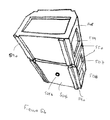
- FIGS 5a and 5b are partial schematic views of a fourth embodiment of the confinement enclosure of the invention designated generally by reference numeral 51.
- the confinement enclosure 51 comprises a one-piece moulded housing 52 having a profile which is substantially semi-octagonal.
- the one-piece moulded housing 52 defines an interior confinement space.
- the one-piece moulded housing 52 has an internal circumferential rib 520 (see Figure 5a ) which is substantially V-shaped.
- the internal circumferential rib 520 allows netting to be fitted non-protruberantly in a recess so as to prevent abrasion.
- a proximal end 500, a distal end 501, a ceiling 503 and a floor 504 of the one-piece moulded housing 52 are uniformly perforated with holes, these and other surface features are omitted from Figures 5a and 5b for clarity. Nonetheless the surface is perforated with the exception of a part of the floor 504 which is solid.
- a first side wall 505 is equipped with access windows 512 and 513 for access to the interior confinement space and an entrance window 511 for marine creatures.
- a second side wall 506 is equipped with an entrance window 507 for marine creatures and side windows 508 and 509 which are perforated.
- Each of the entrance windows 507 and 511, access windows 512 and 513 and side windows 508 and 509 is recessed with a substantially orthogonal return surface (550 for example).
- the floor 504 is equipped with a pair of parallel spaced apart moulded lugs 590 which extend from the proximal end 500 to the distal end 501. Inside the confinement enclosure 51, the moulded lugs 590 are hollow and able to receive and secure weighted ballasts.
- the ceiling 503 is equipped with a pair of parallel spaced apart moulded grooves 591 which extend from the proximal end 500 to the distal end 501 at the apex with the first side wall 505 and second side wall 506 respectively.
- the moulded lugs 590 and moulded grooves 591 are complementarily shaped to permit mutual vertical stacking of multiple confinement enclosures 51.
- the access windows 512 and 513 and an access window 501 a in the distal end 501 are used generally for access to the interior confinement space for the purposes of attaching reticulated material internally during the manufacture of a marine entrapment assembly.
- the access window 512 is used for loading bait on the bait retaining rope.
- the access window 513 is used for retrieving catch.
- the distal end 501 may be cut away by the assembler to create the access window 501a.
- the access windows 512 and 513 are generally closed by a curtain of reticulated material which is attached to the one-piece moulded housing 52 at the return surfaces 550.
- the window 501a is closed by re-attaching the cutaway part of the distal end 501 with rope.
- the interior confinement space is compartmentalised into a baiting chamber adjacent to the entrance window 511 and an exit chamber adjacent to the access window 513 by a constriction funnel.
- the constriction funnel serves to constrict the passage between the baiting chamber and the exit chamber and prevent the return of entrapped marine creatures from the exit chamber to the baiting chamber.
Landscapes
- Life Sciences & Earth Sciences (AREA)
- Environmental Sciences (AREA)
- Animal Husbandry (AREA)
- Biodiversity & Conservation Biology (AREA)
- Catching Or Destruction (AREA)
- Farming Of Fish And Shellfish (AREA)
Applications Claiming Priority (2)
| Application Number | Priority Date | Filing Date | Title |
|---|---|---|---|
| GB0910900A GB0910900D0 (en) | 2009-06-24 | 2009-06-24 | Enclosure |
| GB0919023A GB0919023D0 (en) | 2009-06-24 | 2009-10-30 | Enclosure |
Publications (3)
| Publication Number | Publication Date |
|---|---|
| EP2269447A2 true EP2269447A2 (de) | 2011-01-05 |
| EP2269447A3 EP2269447A3 (de) | 2011-11-02 |
| EP2269447B1 EP2269447B1 (de) | 2013-03-27 |
Family
ID=40972707
Family Applications (1)
| Application Number | Title | Priority Date | Filing Date |
|---|---|---|---|
| EP10166700A Not-in-force EP2269447B1 (de) | 2009-06-24 | 2010-06-21 | Eingrenzungsbehälter |
Country Status (2)
| Country | Link |
|---|---|
| EP (1) | EP2269447B1 (de) |
| GB (2) | GB0910900D0 (de) |
Citations (1)
| Publication number | Priority date | Publication date | Assignee | Title |
|---|---|---|---|---|
| GB2350042A (en) | 1999-04-29 | 2000-11-22 | Stephen Anthony Barker | A marine entrapment device |
Family Cites Families (2)
| Publication number | Priority date | Publication date | Assignee | Title |
|---|---|---|---|---|
| US3826032A (en) * | 1973-01-31 | 1974-07-30 | F Torngren | Apparatus for trapping certain crustaceans and the like |
| US4258496A (en) * | 1979-09-26 | 1981-03-31 | Leone Anthony J | Lobster trap |
-
2009
- 2009-06-24 GB GB0910900A patent/GB0910900D0/en not_active Ceased
- 2009-10-30 GB GB0919023A patent/GB0919023D0/en not_active Ceased
-
2010
- 2010-06-21 EP EP10166700A patent/EP2269447B1/de not_active Not-in-force
Patent Citations (1)
| Publication number | Priority date | Publication date | Assignee | Title |
|---|---|---|---|---|
| GB2350042A (en) | 1999-04-29 | 2000-11-22 | Stephen Anthony Barker | A marine entrapment device |
Also Published As
| Publication number | Publication date |
|---|---|
| GB0919023D0 (en) | 2009-12-16 |
| EP2269447B1 (de) | 2013-03-27 |
| GB0910900D0 (en) | 2009-08-05 |
| EP2269447A3 (de) | 2011-11-02 |
Similar Documents
| Publication | Publication Date | Title |
|---|---|---|
| US3821861A (en) | Trap for fishing | |
| US4864770A (en) | Collapsible crustacean trap | |
| US3497989A (en) | Shellfish trap | |
| WO2012003537A1 (en) | A collapsible crustacean trap | |
| CA2152026A1 (en) | Collapsible lobster trap | |
| KR101278858B1 (ko) | 외해 수중 침하식 밀폐형 가두리 양식장 | |
| US5343442A (en) | Process and device for catching fish | |
| JP3157283U (ja) | 魚介藻類育成用収容体 | |
| EP3986126B1 (de) | Fischbecken für aquakultur mit mortalitätsfalle | |
| EP2269447B1 (de) | Eingrenzungsbehälter | |
| JP2001120105A (ja) | 連段養殖かご | |
| KR200451173Y1 (ko) | 토봉용 벌통 | |
| KR102374742B1 (ko) | 어로용 통발 | |
| US20200015463A1 (en) | Trap | |
| CN106614402B (zh) | 胡蜂饲喂器及胡蜂养殖饲喂器 | |
| CN210248028U (zh) | 一种蟾蜍养殖用喂食机 | |
| JP6634143B1 (ja) | 貝類の養殖方法およびこれに使用する観音開き式の養殖かご | |
| CN109042426B (zh) | 一种基于人工智能鱼饲料投放装置 | |
| CN219108481U (zh) | 一种小龙虾工厂化产卵孵化装置 | |
| JP2013215170A (ja) | 人工着底礁 | |
| KR20050053576A (ko) | 해파리 분리배출장치 | |
| CN208016731U (zh) | 一种捕虾装置 | |
| CN212368188U (zh) | 一种海鲜产品运输用存储结构 | |
| CN211168359U (zh) | 一种水产品处理废物收集筒 | |
| CN110754424A (zh) | 一种毒蛇养殖箱 |
Legal Events
| Date | Code | Title | Description |
|---|---|---|---|
| PUAI | Public reference made under article 153(3) epc to a published international application that has entered the european phase |
Free format text: ORIGINAL CODE: 0009012 |
|
| AK | Designated contracting states |
Kind code of ref document: A2 Designated state(s): AL AT BE BG CH CY CZ DE DK EE ES FI FR GB GR HR HU IE IS IT LI LT LU LV MC MK MT NL NO PL PT RO SE SI SK SM TR |
|
| AX | Request for extension of the european patent |
Extension state: BA ME RS |
|
| PUAL | Search report despatched |
Free format text: ORIGINAL CODE: 0009013 |
|
| AK | Designated contracting states |
Kind code of ref document: A3 Designated state(s): AL AT BE BG CH CY CZ DE DK EE ES FI FR GB GR HR HU IE IS IT LI LT LU LV MC MK MT NL NO PL PT RO SE SI SK SM TR |
|
| AX | Request for extension of the european patent |
Extension state: BA ME RS |
|
| RIC1 | Information provided on ipc code assigned before grant |
Ipc: A01K 69/08 20060101AFI20110923BHEP |
|
| 17P | Request for examination filed |
Effective date: 20120502 |
|
| 17Q | First examination report despatched |
Effective date: 20120605 |
|
| GRAP | Despatch of communication of intention to grant a patent |
Free format text: ORIGINAL CODE: EPIDOSNIGR1 |
|
| GRAS | Grant fee paid |
Free format text: ORIGINAL CODE: EPIDOSNIGR3 |
|
| GRAA | (expected) grant |
Free format text: ORIGINAL CODE: 0009210 |
|
| AK | Designated contracting states |
Kind code of ref document: B1 Designated state(s): AL AT BE BG CH CY CZ DE DK EE ES FI FR GB GR HR HU IE IS IT LI LT LU LV MC MK MT NL NO PL PT RO SE SI SK SM TR |
|
| REG | Reference to a national code |
Ref country code: GB Ref legal event code: FG4D |
|
| REG | Reference to a national code |
Ref country code: CH Ref legal event code: EP |
|
| REG | Reference to a national code |
Ref country code: AT Ref legal event code: REF Ref document number: 602772 Country of ref document: AT Kind code of ref document: T Effective date: 20130415 |
|
| REG | Reference to a national code |
Ref country code: IE Ref legal event code: FG4D |
|
| REG | Reference to a national code |
Ref country code: DE Ref legal event code: R096 Ref document number: 602010005737 Country of ref document: DE Effective date: 20130523 |
|
| PG25 | Lapsed in a contracting state [announced via postgrant information from national office to epo] |
Ref country code: LT Free format text: LAPSE BECAUSE OF FAILURE TO SUBMIT A TRANSLATION OF THE DESCRIPTION OR TO PAY THE FEE WITHIN THE PRESCRIBED TIME-LIMIT Effective date: 20130327 Ref country code: NO Free format text: LAPSE BECAUSE OF FAILURE TO SUBMIT A TRANSLATION OF THE DESCRIPTION OR TO PAY THE FEE WITHIN THE PRESCRIBED TIME-LIMIT Effective date: 20130627 Ref country code: BG Free format text: LAPSE BECAUSE OF FAILURE TO SUBMIT A TRANSLATION OF THE DESCRIPTION OR TO PAY THE FEE WITHIN THE PRESCRIBED TIME-LIMIT Effective date: 20130627 Ref country code: SE Free format text: LAPSE BECAUSE OF FAILURE TO SUBMIT A TRANSLATION OF THE DESCRIPTION OR TO PAY THE FEE WITHIN THE PRESCRIBED TIME-LIMIT Effective date: 20130327 |
|
| REG | Reference to a national code |
Ref country code: AT Ref legal event code: MK05 Ref document number: 602772 Country of ref document: AT Kind code of ref document: T Effective date: 20130327 |
|
| REG | Reference to a national code |
Ref country code: LT Ref legal event code: MG4D |
|
| PG25 | Lapsed in a contracting state [announced via postgrant information from national office to epo] |
Ref country code: GR Free format text: LAPSE BECAUSE OF FAILURE TO SUBMIT A TRANSLATION OF THE DESCRIPTION OR TO PAY THE FEE WITHIN THE PRESCRIBED TIME-LIMIT Effective date: 20130628 Ref country code: SI Free format text: LAPSE BECAUSE OF FAILURE TO SUBMIT A TRANSLATION OF THE DESCRIPTION OR TO PAY THE FEE WITHIN THE PRESCRIBED TIME-LIMIT Effective date: 20130327 Ref country code: LV Free format text: LAPSE BECAUSE OF FAILURE TO SUBMIT A TRANSLATION OF THE DESCRIPTION OR TO PAY THE FEE WITHIN THE PRESCRIBED TIME-LIMIT Effective date: 20130327 Ref country code: FI Free format text: LAPSE BECAUSE OF FAILURE TO SUBMIT A TRANSLATION OF THE DESCRIPTION OR TO PAY THE FEE WITHIN THE PRESCRIBED TIME-LIMIT Effective date: 20130327 |
|
| REG | Reference to a national code |
Ref country code: NL Ref legal event code: VDEP Effective date: 20130327 |
|
| PG25 | Lapsed in a contracting state [announced via postgrant information from national office to epo] |
Ref country code: BE Free format text: LAPSE BECAUSE OF FAILURE TO SUBMIT A TRANSLATION OF THE DESCRIPTION OR TO PAY THE FEE WITHIN THE PRESCRIBED TIME-LIMIT Effective date: 20130327 Ref country code: HR Free format text: LAPSE BECAUSE OF FAILURE TO SUBMIT A TRANSLATION OF THE DESCRIPTION OR TO PAY THE FEE WITHIN THE PRESCRIBED TIME-LIMIT Effective date: 20130327 |
|
| PG25 | Lapsed in a contracting state [announced via postgrant information from national office to epo] |
Ref country code: NL Free format text: LAPSE BECAUSE OF FAILURE TO SUBMIT A TRANSLATION OF THE DESCRIPTION OR TO PAY THE FEE WITHIN THE PRESCRIBED TIME-LIMIT Effective date: 20130327 Ref country code: ES Free format text: LAPSE BECAUSE OF FAILURE TO SUBMIT A TRANSLATION OF THE DESCRIPTION OR TO PAY THE FEE WITHIN THE PRESCRIBED TIME-LIMIT Effective date: 20130708 Ref country code: IS Free format text: LAPSE BECAUSE OF FAILURE TO SUBMIT A TRANSLATION OF THE DESCRIPTION OR TO PAY THE FEE WITHIN THE PRESCRIBED TIME-LIMIT Effective date: 20130727 Ref country code: CZ Free format text: LAPSE BECAUSE OF FAILURE TO SUBMIT A TRANSLATION OF THE DESCRIPTION OR TO PAY THE FEE WITHIN THE PRESCRIBED TIME-LIMIT Effective date: 20130327 Ref country code: SK Free format text: LAPSE BECAUSE OF FAILURE TO SUBMIT A TRANSLATION OF THE DESCRIPTION OR TO PAY THE FEE WITHIN THE PRESCRIBED TIME-LIMIT Effective date: 20130327 Ref country code: EE Free format text: LAPSE BECAUSE OF FAILURE TO SUBMIT A TRANSLATION OF THE DESCRIPTION OR TO PAY THE FEE WITHIN THE PRESCRIBED TIME-LIMIT Effective date: 20130327 Ref country code: PT Free format text: LAPSE BECAUSE OF FAILURE TO SUBMIT A TRANSLATION OF THE DESCRIPTION OR TO PAY THE FEE WITHIN THE PRESCRIBED TIME-LIMIT Effective date: 20130729 Ref country code: RO Free format text: LAPSE BECAUSE OF FAILURE TO SUBMIT A TRANSLATION OF THE DESCRIPTION OR TO PAY THE FEE WITHIN THE PRESCRIBED TIME-LIMIT Effective date: 20130327 Ref country code: AT Free format text: LAPSE BECAUSE OF FAILURE TO SUBMIT A TRANSLATION OF THE DESCRIPTION OR TO PAY THE FEE WITHIN THE PRESCRIBED TIME-LIMIT Effective date: 20130327 |
|
| PG25 | Lapsed in a contracting state [announced via postgrant information from national office to epo] |
Ref country code: CY Free format text: LAPSE BECAUSE OF FAILURE TO SUBMIT A TRANSLATION OF THE DESCRIPTION OR TO PAY THE FEE WITHIN THE PRESCRIBED TIME-LIMIT Effective date: 20130327 Ref country code: PL Free format text: LAPSE BECAUSE OF FAILURE TO SUBMIT A TRANSLATION OF THE DESCRIPTION OR TO PAY THE FEE WITHIN THE PRESCRIBED TIME-LIMIT Effective date: 20130327 |
|
| PG25 | Lapsed in a contracting state [announced via postgrant information from national office to epo] |
Ref country code: DK Free format text: LAPSE BECAUSE OF FAILURE TO SUBMIT A TRANSLATION OF THE DESCRIPTION OR TO PAY THE FEE WITHIN THE PRESCRIBED TIME-LIMIT Effective date: 20130327 Ref country code: MC Free format text: LAPSE BECAUSE OF FAILURE TO SUBMIT A TRANSLATION OF THE DESCRIPTION OR TO PAY THE FEE WITHIN THE PRESCRIBED TIME-LIMIT Effective date: 20130327 |
|
| PLBE | No opposition filed within time limit |
Free format text: ORIGINAL CODE: 0009261 |
|
| STAA | Information on the status of an ep patent application or granted ep patent |
Free format text: STATUS: NO OPPOSITION FILED WITHIN TIME LIMIT |
|
| PG25 | Lapsed in a contracting state [announced via postgrant information from national office to epo] |
Ref country code: IT Free format text: LAPSE BECAUSE OF FAILURE TO SUBMIT A TRANSLATION OF THE DESCRIPTION OR TO PAY THE FEE WITHIN THE PRESCRIBED TIME-LIMIT Effective date: 20130327 |
|
| 26N | No opposition filed |
Effective date: 20140103 |
|
| REG | Reference to a national code |
Ref country code: IE Ref legal event code: MM4A |
|
| REG | Reference to a national code |
Ref country code: DE Ref legal event code: R119 Ref document number: 602010005737 Country of ref document: DE Effective date: 20140101 |
|
| REG | Reference to a national code |
Ref country code: FR Ref legal event code: ST Effective date: 20140228 |
|
| PG25 | Lapsed in a contracting state [announced via postgrant information from national office to epo] |
Ref country code: DE Free format text: LAPSE BECAUSE OF NON-PAYMENT OF DUE FEES Effective date: 20140101 Ref country code: IE Free format text: LAPSE BECAUSE OF NON-PAYMENT OF DUE FEES Effective date: 20130621 |
|
| PG25 | Lapsed in a contracting state [announced via postgrant information from national office to epo] |
Ref country code: FR Free format text: LAPSE BECAUSE OF NON-PAYMENT OF DUE FEES Effective date: 20130701 |
|
| REG | Reference to a national code |
Ref country code: CH Ref legal event code: PL |
|
| PG25 | Lapsed in a contracting state [announced via postgrant information from national office to epo] |
Ref country code: MT Free format text: LAPSE BECAUSE OF FAILURE TO SUBMIT A TRANSLATION OF THE DESCRIPTION OR TO PAY THE FEE WITHIN THE PRESCRIBED TIME-LIMIT Effective date: 20130327 |
|
| PG25 | Lapsed in a contracting state [announced via postgrant information from national office to epo] |
Ref country code: LI Free format text: LAPSE BECAUSE OF NON-PAYMENT OF DUE FEES Effective date: 20140630 Ref country code: CH Free format text: LAPSE BECAUSE OF NON-PAYMENT OF DUE FEES Effective date: 20140630 |
|
| PG25 | Lapsed in a contracting state [announced via postgrant information from national office to epo] |
Ref country code: SM Free format text: LAPSE BECAUSE OF FAILURE TO SUBMIT A TRANSLATION OF THE DESCRIPTION OR TO PAY THE FEE WITHIN THE PRESCRIBED TIME-LIMIT Effective date: 20130327 |
|
| PG25 | Lapsed in a contracting state [announced via postgrant information from national office to epo] |
Ref country code: TR Free format text: LAPSE BECAUSE OF FAILURE TO SUBMIT A TRANSLATION OF THE DESCRIPTION OR TO PAY THE FEE WITHIN THE PRESCRIBED TIME-LIMIT Effective date: 20130327 |
|
| PG25 | Lapsed in a contracting state [announced via postgrant information from national office to epo] |
Ref country code: HU Free format text: LAPSE BECAUSE OF FAILURE TO SUBMIT A TRANSLATION OF THE DESCRIPTION OR TO PAY THE FEE WITHIN THE PRESCRIBED TIME-LIMIT; INVALID AB INITIO Effective date: 20100621 Ref country code: MK Free format text: LAPSE BECAUSE OF FAILURE TO SUBMIT A TRANSLATION OF THE DESCRIPTION OR TO PAY THE FEE WITHIN THE PRESCRIBED TIME-LIMIT Effective date: 20130327 Ref country code: LU Free format text: LAPSE BECAUSE OF NON-PAYMENT OF DUE FEES Effective date: 20130621 |
|
| REG | Reference to a national code |
Ref country code: GB Ref legal event code: 732E Free format text: REGISTERED BETWEEN 20160505 AND 20160511 |
|
| PGFP | Annual fee paid to national office [announced via postgrant information from national office to epo] |
Ref country code: GB Payment date: 20160620 Year of fee payment: 7 |
|
| GBPC | Gb: european patent ceased through non-payment of renewal fee |
Effective date: 20170621 |
|
| PG25 | Lapsed in a contracting state [announced via postgrant information from national office to epo] |
Ref country code: GB Free format text: LAPSE BECAUSE OF NON-PAYMENT OF DUE FEES Effective date: 20170621 |
|
| PG25 | Lapsed in a contracting state [announced via postgrant information from national office to epo] |
Ref country code: AL Free format text: LAPSE BECAUSE OF FAILURE TO SUBMIT A TRANSLATION OF THE DESCRIPTION OR TO PAY THE FEE WITHIN THE PRESCRIBED TIME-LIMIT Effective date: 20130327 |