EP2268370B1 - Integrierte anordnung zur koppelung eines skistocks an einen ski - Google Patents
Integrierte anordnung zur koppelung eines skistocks an einen ski Download PDFInfo
- Publication number
- EP2268370B1 EP2268370B1 EP09720287.3A EP09720287A EP2268370B1 EP 2268370 B1 EP2268370 B1 EP 2268370B1 EP 09720287 A EP09720287 A EP 09720287A EP 2268370 B1 EP2268370 B1 EP 2268370B1
- Authority
- EP
- European Patent Office
- Prior art keywords
- ski
- pole
- coupling
- coupling formation
- skis
- Prior art date
- Legal status (The legal status is an assumption and is not a legal conclusion. Google has not performed a legal analysis and makes no representation as to the accuracy of the status listed.)
- Active
Links
- 230000008878 coupling Effects 0.000 title claims description 391
- 238000010168 coupling process Methods 0.000 title claims description 391
- 238000005859 coupling reaction Methods 0.000 title claims description 391
- 230000015572 biosynthetic process Effects 0.000 claims description 288
- 230000027455 binding Effects 0.000 claims description 128
- 238000009739 binding Methods 0.000 claims description 128
- 238000005755 formation reaction Methods 0.000 description 276
- 238000000034 method Methods 0.000 description 27
- 230000009977 dual effect Effects 0.000 description 26
- 238000003780 insertion Methods 0.000 description 20
- 230000037431 insertion Effects 0.000 description 20
- 239000000463 material Substances 0.000 description 15
- 230000008901 benefit Effects 0.000 description 14
- 230000009471 action Effects 0.000 description 10
- 230000004048 modification Effects 0.000 description 10
- 238000012986 modification Methods 0.000 description 10
- 230000008569 process Effects 0.000 description 8
- 239000004677 Nylon Substances 0.000 description 7
- 229920001778 nylon Polymers 0.000 description 7
- 229920000642 polymer Polymers 0.000 description 6
- 239000000853 adhesive Substances 0.000 description 4
- 230000001070 adhesive effect Effects 0.000 description 4
- 239000004744 fabric Substances 0.000 description 4
- 239000004033 plastic Substances 0.000 description 4
- 230000002441 reversible effect Effects 0.000 description 4
- 238000013459 approach Methods 0.000 description 3
- 230000006835 compression Effects 0.000 description 3
- 238000007906 compression Methods 0.000 description 3
- 238000004519 manufacturing process Methods 0.000 description 3
- 230000007935 neutral effect Effects 0.000 description 3
- 238000002360 preparation method Methods 0.000 description 3
- 238000003825 pressing Methods 0.000 description 3
- 229910052782 aluminium Inorganic materials 0.000 description 2
- XAGFODPZIPBFFR-UHFFFAOYSA-N aluminium Chemical compound [Al] XAGFODPZIPBFFR-UHFFFAOYSA-N 0.000 description 2
- 210000000078 claw Anatomy 0.000 description 2
- 230000000295 complement effect Effects 0.000 description 2
- 238000010276 construction Methods 0.000 description 2
- 230000006378 damage Effects 0.000 description 2
- 239000011521 glass Substances 0.000 description 2
- 239000003292 glue Substances 0.000 description 2
- 230000006872 improvement Effects 0.000 description 2
- 238000005304 joining Methods 0.000 description 2
- 230000007246 mechanism Effects 0.000 description 2
- 239000002184 metal Substances 0.000 description 2
- 229910052751 metal Inorganic materials 0.000 description 2
- 230000002265 prevention Effects 0.000 description 2
- 230000000087 stabilizing effect Effects 0.000 description 2
- 229910001220 stainless steel Inorganic materials 0.000 description 2
- 239000010935 stainless steel Substances 0.000 description 2
- 238000003466 welding Methods 0.000 description 2
- 229920000049 Carbon (fiber) Polymers 0.000 description 1
- 241001166076 Diapheromera femorata Species 0.000 description 1
- FYYHWMGAXLPEAU-UHFFFAOYSA-N Magnesium Chemical compound [Mg] FYYHWMGAXLPEAU-UHFFFAOYSA-N 0.000 description 1
- RTAQQCXQSZGOHL-UHFFFAOYSA-N Titanium Chemical compound [Ti] RTAQQCXQSZGOHL-UHFFFAOYSA-N 0.000 description 1
- 208000027418 Wounds and injury Diseases 0.000 description 1
- 230000001154 acute effect Effects 0.000 description 1
- 210000003484 anatomy Anatomy 0.000 description 1
- 230000003466 anti-cipated effect Effects 0.000 description 1
- 238000005452 bending Methods 0.000 description 1
- 230000008275 binding mechanism Effects 0.000 description 1
- 239000004917 carbon fiber Substances 0.000 description 1
- 239000002131 composite material Substances 0.000 description 1
- 230000001010 compromised effect Effects 0.000 description 1
- 230000036461 convulsion Effects 0.000 description 1
- 230000001419 dependent effect Effects 0.000 description 1
- 238000011161 development Methods 0.000 description 1
- 230000000694 effects Effects 0.000 description 1
- 230000001747 exhibiting effect Effects 0.000 description 1
- 230000005484 gravity Effects 0.000 description 1
- 208000014674 injury Diseases 0.000 description 1
- 229910052749 magnesium Inorganic materials 0.000 description 1
- 239000011777 magnesium Substances 0.000 description 1
- 230000035755 proliferation Effects 0.000 description 1
- 239000011435 rock Substances 0.000 description 1
- 238000006748 scratching Methods 0.000 description 1
- 230000002393 scratching effect Effects 0.000 description 1
- 238000000926 separation method Methods 0.000 description 1
- 238000003860 storage Methods 0.000 description 1
- 208000005123 swayback Diseases 0.000 description 1
- 239000010936 titanium Substances 0.000 description 1
- 229910052719 titanium Inorganic materials 0.000 description 1
Images


Classifications
-
- A—HUMAN NECESSITIES
- A63—SPORTS; GAMES; AMUSEMENTS
- A63C—SKATES; SKIS; ROLLER SKATES; DESIGN OR LAYOUT OF COURTS, RINKS OR THE LIKE
- A63C11/00—Accessories for skiing or snowboarding
- A63C11/02—Devices for stretching, clamping or pressing skis or snowboards for transportation or storage
- A63C11/023—Carrying-devices
- A63C11/025—Carrying-devices for skis or ski-sticks
-
- A—HUMAN NECESSITIES
- A63—SPORTS; GAMES; AMUSEMENTS
- A63C—SKATES; SKIS; ROLLER SKATES; DESIGN OR LAYOUT OF COURTS, RINKS OR THE LIKE
- A63C11/00—Accessories for skiing or snowboarding
-
- A—HUMAN NECESSITIES
- A63—SPORTS; GAMES; AMUSEMENTS
- A63C—SKATES; SKIS; ROLLER SKATES; DESIGN OR LAYOUT OF COURTS, RINKS OR THE LIKE
- A63C11/00—Accessories for skiing or snowboarding
- A63C11/22—Ski-sticks
- A63C11/228—Accessories
-
- A—HUMAN NECESSITIES
- A63—SPORTS; GAMES; AMUSEMENTS
- A63C—SKATES; SKIS; ROLLER SKATES; DESIGN OR LAYOUT OF COURTS, RINKS OR THE LIKE
- A63C11/00—Accessories for skiing or snowboarding
- A63C11/22—Ski-sticks
- A63C11/221—Ski-sticks telescopic, e.g. for varying the length or for damping shocks
Definitions
- the present invention relates to snow skiing, specifically to a system of attaching skis and poles together for convenient carriage.
- a difficult task for a snow skier is any trip on foot with skis and poles in hand, particularly when a skier is tired.
- Snow skis are heavy, awkwardly shaped, long, and have sharp edges. Skis do not have handles. Skiers often must carry two skis in one hand and at the same time carrying two ski poles in the other hand when their hands are covered by bulky ski gloves.
- Most skiers take time to arrange the running surfaces, or "bases,” of the skis together and may attempt to use the "interlocking" ski brakes to hold skis together in order to hoist the skis over their shoulder and carry them while walking in heavy, stiff ski boots. It is often difficult to hold both skis and poles when attempting to insert the tail of the skis into the vertical racks found at lodges, on gondolas and buses.
- Skis and ski poles are usually hand carried in situations that may be classified by distance into four categories.
- the first is a short haul. This haul can measure from just a few meters to possibly fifty meters long.
- a common short haul trip is from the house, hotel, or car to the ski bus stop, or from the base of the slope to a gondola or lift. It can be from the ski bus to the vertical ski racks next to the lodge or the center of the ski village.
- Various short hauls between rental shops, bars, restaurants or retailers are also common with today's modern ski villages.
- the second carrying situation is an intermediate haul, which often involves transport between a car, condominium, hotel, restaurant or other location to the base of the slope where the lift and gondola are located. This intermediate haul is often performed while wearing ski boots, but if more comfortable walking shoes are donned, ski boots may also need to be carried.
- the remaining two situations are the long haul, which may arise in the context of cross country and extreme skiing, and the travel by conveyance, wherein the skis are transported over long distances on airplanes, on boats, or in cars.
- long haul cases the time it takes to place the skis in an over-the-shoulder bag, holster, or other apparatus may be justified; for travel by conveyance, large bag enclosures, tubes and automobile racks are more practical for travel from one's home to a remote ski resort hundreds or thousands of miles away.
- Prior art fails in solving six basic needs presented by the short and intermediate hauls: (1) the need for speedy attachment; (2) the need for a convenient handle; (3) the need for rigid control in handling; (4) the need to keep the back end of the skis clear for vertical rack insertion; (5) the need for versatility, such as keeping the skis apart for use in automobile racks; and (6) the need to eliminate separately carried items, which must be stored or can be lost. While some devices meet some of these needs, none of the currently available methods meet all six needs simultaneously.
- Bags and other large enclosures are useful for long haul and travel by conveyance situations, and may be adequate for intermediate hauls, but are impractical for use on the slopes. Most of them are designed for travel from a home to a remote ski resort hundreds or thousands of miles away. While a bag or tube may be used for transport around a ski village, the size of such a device and the time required to use it make it difficult to use on the slopes. Opening the enclosure, removing all four items, closing it back up, and then finding a place to store it is impractical for short hauls.
- holsters For short and intermediate hauls, holsters have discernable disadvantages. They are somewhat bulky and require time to put on or take off. If left on, they can interfere with a skier's movement and may be uncomfortable. Many holsters, such as those disclosed by U.S. Publication 2007/0125818 to Forster and U.S. Publication 2007/0210570 to Erichsen , do not provide for the poles. Also, holster arrangements are limited to conditions when it is necessary to couple the skis together, are inconvenient for short hauls, and do not provide speed of attachment. The handle usually consists of fabric from the holster, which is not necessarily convenient.
- skis are devoid of easy handling properties. Although once out of the holster, skis are not encumbered for insertion into racks, one still has the problem of handling the poles and skis simultaneously while trying to insert the skis into the rack.
- Strapping solutions tend to use a loop or configuration of loops of fabric strapping around the skis, bindings, and/or the poles.
- a strap handle is usually attached as well.
- Most strap systems use hook and loop fabrics, buckles, ladder lock retainers, snaps and the like to wrap the straps around either the skis, bindings, and/or poles and then to adjust and tighten them into a desired position.
- the strap of U.S. Publication No. 2005/0199660 to Rolf uses loose, non adjustable loops to avoid detailed snapping, threading and pulling (which can be difficult when wearing thick ski gloves).
- U.S. Publication No. 2005/0199660 to Rolf uses loose, non adjustable loops to avoid detailed snapping, threading and pulling (which can be difficult when wearing thick ski gloves).
- U.S. Publication No. 2006/0076378 to Hall discloses a strapping system that may be handheld or shoulder mounted, while U.S. Patent No. 4,165,027 to Briggs and WO 94/28986 to Burr seek to position the poles as handles.
- WO 94/28986 to Burr is significant as it teaches the use of two straps are provided to enable the user to bind the poles tightly to the skis to form an easily graspable handle, however, the straps require time to place properly, constitute additional gear, do not leave the back end of the skis unencumbered, and do not readily create a rigid carrying system.
- the straps can be tightened to pull the poles down in a vertical fashion against the ski bindings, there is nothing on the ski bindings to keep the poles from sliding from side to side and falling off the binding, resulting in a loose strap.
- the Burr method contemplates that the handle end of the poles can be strapped to the skis. In order to accomplish that objective, the toe piece of the binding must have an extremely low profile. However, most modern toe pieces have a relatively high profile which would not allow the poles to be pushed down to the skis without bending the poles.
- Integrated devices eliminate separately carried items by definition, as their features are integrated into or permanently affixed to the poles and skis.
- Some current integrated solutions provide for rigid control, but not all provide handles, and often do not allow for quick attachment or a clean back end for rack insertion, and may require the skis to be arranged base-to-base.
- One group of integrated devices constitute an single point, pivotal hoist, and involve using the tip end of the pole to connect to the ski near the toe piece and hoist the skis over the shoulders to be carried by the poles (like a knapsack or rucksack is carried with a walking stick).
- the planar connection between the ski poles and the skis may actually involve more than one geometric point, for all practical purposes, the system is connected at only one juncture.
- Such devices are described in U.S. Patent Nos. 4,630,842 and 4,702,495 to Roda , and involve mounting an attachment with tubular hole to the top of the ski, at a point in front of the toe piece of the bindings, with the tubular hole oriented perpendicular to the length of the ski.
- any rigidity created by the length of the tubular connection in Roda '842 could bend the tip of the pole.
- this method leaves the skis gravitationally swinging from the poles and limits severely the orientation of handling positions.
- U.S. Patent No. 4,102,163 to Bosch discloses an integrated locking system wherein the skis are fixed together with clamps permanently affixed to the ski, and requires substantial time to arrange the skis and complete the clamping and resulting in a package with no real handle.
- U.S. Patent No. 7,273,233 to Moller describes a ski clip which constitutes a fold-out, two-pronged fork-like clip attached to the mid-portion of the pole which is designed to pivot out and then hold two skis together in a base-to-base orientation while simultaneously allowing the ski poles to hang at the pivot point of the clip attachment from the tip end of the skis.
- Both skis must be grasped by one hand somewhere in the vicinity of the bindings or the upper end of the skis without the aid of a handle. Getting ones glove-covered hand around the width of the skis is problematic. The positions of the clipped-on poles actually hinder the grasping of the unit by obstructing the area which would normally be occupied by a holder's arm. The holder is now forced to grab the skis by their width in order to avoid the poles. Moreover, an attempt to grab the unit by the poles results in a loose arrangement because of the single pivot point by which the poles have been attached. Applying enough force to the poles to actually pick up the unit may disengage the poles and clip from the skis, as there is no latch holding the forks to the skis.
- Moller '233 does not allow for rigidity in handling. Moller '233 keeps the items together to be held in one hand so that one could reach for a lift ticket or one could hold on to a stability bar while standing in a bus or gondola, and leaves the back end of the skis clear for rack insertion. However, it requires a cumbersome effort to get to the result, and does not provide a convenient handle. Moller '233 also demands the skis be clamped together.
- a second group of integrated solutions modifies the ski pole basket All of these devices require effort arranging the skis in a base-to-base configuration and then a cumbersome securing process.
- U.S. Patent No. 4,175,683 to Shields provides a basket with a pullout clamping assembly which is removed from the basket, then wrapped around a pair of base-to-base arranged skis and then reinserted into the basket, holding the ski's to the basket.
- This process must be repeated after the poles are first joined together in opposite directions.
- Speed of attachment is completely absent in this method.
- the actual success of attachment is suspect with many of today's skis, which are trending toward very wide configurations known as "fat" skis.
- Step one of attachment is the same: the poles are interlocked in opposing directions using recesses in the basket.
- Step two of the process is the same: one places the skis in a base-to-base orientation.
- Step three is the same: place the skis into the rectangular basket recess.
- the ski securement is different. Rather than using a plastic clip, the pole strap is wrapped around the entire unit. Again, need number one, speedy attachment, remains unsatisfied. The clearance of the poles from the skis (while improved) may not be sufficient for easy grasping by a glove clad hand only partially satisfying need number two.
- U.S. Patent No. 3,687,472 to Struble Jr. modifies the pole basket, handles, and straps.
- the baskets contain recesses to accommodate the shaft of the other pole near the tip end such that the poles can be joined together near the tip.
- the pole handles are partially covered with "ribs" (and or hook and loop fabric) such that they can be connected together at the handle end.
- the baskets also have large rectangular cut-outs in them to accommodate the bodies of the skis. According to this arrangement, the poles are first joined together at the basket end then the handle end.
- the skis are inserted into the basket cut-outs in an orientation such that the skis are on the outside of the package and the poles are actually between the skis. Finally, the pole straps are wrapped around the package and snapped to posts on the handle of the opposite pole.
- the Struble '472 system requires a fair amount of time to assemble the package. There is not a handle, although the package is rigid. An alternate version leaves the back end of the skis clear; however, the bound package (with the poles between the skis) may be too wide for rack insertion. Additionally, the single bound package may be cumbersome and not fit onto a conventional automobile rack.
- U.S. Patent No. 4,361,347 to MacIntyre teaches another basket system.
- the MacIntyre '347system employs the same basic method of transversely orienting the poles by way of basket recesses. However, the approach is different with respect to attaching the skis.
- This method employs detent receiving holes in surfaces mounted on one side of each ski, and detented clipping recesses formed into the basket. As in all of the basket methods, it takes significant time and work to place the skis and poles in the proper positions.
- the poles appear to be convenient handles, rigidity and integrity of the connection is not present.
- the flexible material of the baskets does not provide for rigidity, and any significant stress on the flexible basket material may dislodge the skis.
- the "carrying arrangement for the joint transportation of ski sticks and skis" of WO 2007/140754 A1 to Sperlich reveals a self contained apparatus comprising an eyelet attached to the lower 1/3 of the ski pole. Unlike most integrated solutions, the Sperlich '754 arrangement connects to the interlocking ski brake. The final arrangement achieved by this invention does results in a single unit which can be toted by grasping of the ski poles as handles. But the flexibility to carry them separately is removed. Also, to get to the Sperlich '754 arrangement a substantial amount of time and effort are required, negating the advantage of speedy attachment.
- each ski pole eyelet is manually placed around each downward pointing ski brake claw.
- This placement task must be done when the ski brakes are not interlocked or one must risk disengagement of the interlocking ski brakes during the eyelet attaching process.
- many of the larger protrusions and recessed areas on modern interlocking ski brake claws will not easily accommodate looping over of the eyelet for stability.
- Even after all of the above listed efforts the result of the Sperlich '754 arrangement is still a loose ski pole handle which relies on gravity to keep the skis oriented below the poles. There is no rigidity in handling.
- the arrangement does not accommodate vertical positioning of the skis for easy placement in ski racks on buses and gondolas.
- An attempt to vertically orient the ski's by use of the poles as handles may result in failure of the entire arrangement because the top ends of the poles are loosely attached to the front ends of the skis. This equally allows the bottom ends of the skis to sway back and forth limiting the control over the entire ski set. Also, because the tip of the poles extends significantly beyond the heel piece, the Sperlich '754 arrangement further hinders insertion of the ski's tail into racks.
- Kidder Another such device is shown in U.S. Patent No. 3,941,397 to Kidder , which discloses a hook for the tip end of the ski pole is attached to the ski while the other end of poles are loosely attached to each other by the straps which merely sit under the skis and not around them.
- the Kidder '397 device fails to achieve speed of attachment; rigid control in handling; a clean ski for rack insertion; As well as the versatility to get underway without taking time to couple the skis together. Additionally, any attempt at vertical handling will result in the skis falling out of the stretcher formed by the ski pole straps because they do not even surround the skis.
- U.S. Pat. No. 4,129,312 to Loffelholz reveals a locking system which joins a pole and ski by way of circular rings connected to various parts of the ski.
- the pole is unique.
- the top portion of the pole separates from the remainder of the pole and the joining ends of the two pole segments constitute a combination lock.
- the purpose of separating the two pole parts is to allow them to be slipped loosely through the ski mounted rings and then recombined, by way of setting the lock, to form a single unit.
- U.S. Pat. No. 5,951,047 to Dungan describes a locking arrangement which fixes the poles to the skis at only one point, in a configuration similar to the Moller '233 ski clip.
- the primary purpose of this device is theft prevention, although some benefits of carriage are mentioned.
- the Dungan '047 system requires the skis to be oriented base-to-base, the use of a key to unlock the shackles, the placement of the locking units together, the attachment of the shackles, and then the locking with the key. Afterwards, there is a one point attachment near the top of the pole, which sacrifices a rigid handle.
- the user of the Dungan '047 device is encouraged to use a separate and optional ski tie to improve "stability."
- the Dungan '047 arrangement will not offer any benefits different from Moller '233 ski clip unless the tie is used. Even with the tie, the invention obtains only the properties of the Sperlich arrangement, which leave one end of the ski only loosely connected -- all this with the added burden of an additional item to carry and possibly loose.
- German patent application DE2834948A1 discloses a detachable connection of two ski carrying rope ends that is not only used not only to carry the corresponding. ski on its own but can be simultaneously used to carry a ski pole.
- the ski pole is inserted in a horizontal position with its handle to the rear from the end of the ski into or between the carrying rope which is doubled and held together on the automatic heel hold.
- the front jaws are held in a sideways direction without any special attachment, can be also released in the reverse direction.
- French patent application publication FR 2347949 A1 discloses a ski pole provided with a disk mounted at one end above the tip of the pole and a handle grip at the other side of the pole. At least one scraper part projects from the disk to clean the skis, the soles of ski boots and other objects having a flat surface to be cleaned.
- United States patent publication US 4,852,931 discloses a lightweight stowable ski and pole carrier for a pair of skis and a pair of ski poles which clamps the skis together and engages the ski poles to enable a carrier to carry the assemblage with one hand and with the skis extending parallel to the body of the skiers and the ski poles extending at an acute angle with respect to the skis.
- the present invention provides an integrated pole- to-ski quick coupling arrangement and overcomes the above-mentioned disadvantages and drawbacks of the prior art.
- the general purpose of the present invention which will be described subsequently in greater detail, is to provide an integrated pole-to-ski quick coupling arrangement which has all the advantages of the prior art mentioned heretofore and many novel features that result in an integrated pole-to-ski quick coupling arrangement which is not anticipated, rendered obvious, suggested, or even implied by the prior art, either alone or in any combination thereof.
- the present invention is an integrated pole-to-ski coupling arrangement that provides coupling formations on a ski pole and ski that releasably connect the pole and ski to create a unitary ski-pole combination that leaves the rear tail of the ski clear and unencumbered.
- a pole coupling formation may be placed on either the shaft or the grip of the pole. The number, shape, size, and orientation of the coupling formations ensure rapid attachment and a rigid connection.
- the invention may employ pole coupling formations to be attached to existing poles, either on the shaft or on both the grip and the shaft, and the pole formations may be shaped to use the contours of bindings known in the art as ski coupling formations, or such ski coupling formations may optionally be attached directly to the skis or to the bindings.
- the invention may include poles and bindings that have complementary coupling arrangements. A variety of complementary coupling arrangements may be employed.
- the present invention allows a skier that has stepped out of skis to simply place the poles over the skis and snap the poles onto the skis with a quick downward press.
- Each pole is quickly attached to each ski and acts as a convenient handle. After the quick coupling, the skier may simply pick up the skis by the poles and go.
- a skier may handle the skis in a variety of convenient ways. First, one ski may be carried in each hand, balanced at the location of the newly created handle between the bindings. Second, the skier can grab both newly created handles in one hand, as the rigid handles created by the invention allow for holding both skis in one hand, even when the skis are not coupled together.
- the skier may optionally couple the skis together via interlocking ski brakes or other methods such as bands or straps. After the interlocking is complete, the result is a single unit which can be carried in one hand like a guitar case.
- he may carry the skis vertically. This is because the top portion of a pole is coupled to the top of a ski near or on the heel piece of the bindings and the shaft of a pole is coupled to the top of a ski near or on the toe piece of the binding, such that the pole is parallel to the ski top and extends forward with its tip at or near the tip of the ski.
- This unique arrangement leaves the entirety of the ski tail clean for insertion into vertical ski racks. The skier may simply grip the pole at any position forward of the toe piece, lifting the ski in a vertical orientation and drop it into a rack.
- the invention makes it possible to more effectively market ski poles and/or skis by creating an impressive display with the poles attached to the skis at the retail location.
- the present invention is faster and more flexible than the prior art, and solves the problem of quickly removing skis at the end of a ski run and transporting the skis to a rack on a gondola.
- the arrangement provides for two separate rigid pole-ski units. There is no need to interlock the skis together or put them over the shoulder. Grip is firm, balanced and comfortable: the poles, serving as a handles, are firmly affixed to each ski. The poles are parallel to the skis; moreover, the ski pole does not extend into the tail of the ski, leaving it clean for insertion into most modern racks. Much of the pole is over the top of the ski at a balance point between the ski bindings for easy horizontal carriage.
- the bulk of the pole is over the top of the forward length of the ski, extending to the tip to create a long, rigid handle, so the skis may be handled in a vertical position by grabbing the poles nearer the tip using the poles as handles.
- the connection is so rigid that the poles may be used to twirl the ski like a baton without loss of the connection. This allows for quick insertion of both skis and poles into the rack of a moving gondola car, allowing a skier to easily board. In the absence of a gondola car with a rack, the skis may be interlocked and set down, or handled with a single hand. Also, even without interlocking the units, they may be stood vertically gripping both poles with a single hand, freeing the other hand for an onboard stabilizing bar. This scenario is equally applicable to buses.
- Another advantage of the present invention is to allow ski poles to serve as handles for vertically pulling the skis out of a rack, such as that of a moving gondola at the top of a ski run. Disengagement of the pole-to-ski connection is accomplished with a quick jerk on the pole or, in alternate embodiments, with the touch of a small release lever.
- the present invention further allows controlled handing during the process of interlocking the brakes, providing a stiff handle opposite each interlocking brake.
- the present invention allows for the continued refinement and improvement of interlocking ski brake mechanisms or the development of other means of quickly coupling the skis in a base-to-base orientation, and will enhance the ease by which such devices may be used.
- an integrated pole-to-ski quick coupling arrangement which assembles and disassembles quickly with a minimum amount of effort on the part of the skier, provide an integrated pole-to-ski quick coupling arrangement which presents a convenient and versatile handle, provide an integrated pole-to-ski quick coupling arrangement whose handles are rigidly connected to the skis for stability and ease of placement during carriage, provide an integrated pole-to-ski quick coupling arrangement which leaves the tail portion of the ski unencumbered and free of attachments for ease of insertion into ski racks, provide an integrated pole-to-ski quick coupling arrangement which does not require that the skis be bundled or placed together as part of the system, provide an integrated pole-to-ski quick coupling arrangement which does not require any items to be carried separate and apart from the skis and poles themselves, provide an integrated pole-to-ski quick coupling arrangement which enhances the commercial display and sale of skis and poles by allowing them to be displayed with the system in use, and provide a new and improved method of assembling skis and poles for
- FIGS. 1-75 embodiments of the integrated pole-to-ski quick coupling arrangement are illustrated and described. Because each embodiment utilizes various parts of the typical ski pole, ski, and binding, those items and their properties require explanation.
- FIGS. 1-3 display the use of the pole-to-ski-quick coupling arrangement 10 in its intended settings.
- a skier carries poles and skis attached by the pole-to-ski-quick coupling arrangement 10 as two separate units, each exhibiting a pole attached to a ski, in each hand.
- Each pole and ski unit may be carried horizontally at a balance point as shown, may be carried vertically, may be carried at any other desired angle or twirled about like batons.
- FIG. 2 illustrates a skier using the pole-to-ski-quick coupling arrangement 10 to carry two separate pole and ski units in a single hand, thus freeing the opposite hand for grasping objects, such as a stabilizing post in a moving gondola, or for holding other objects, such as ski boots, a cup of coffee, or a child's skis and poles.
- objects such as a stabilizing post in a moving gondola
- other objects such as ski boots, a cup of coffee, or a child's skis and poles.
- FIG. 3 illustrates a skier using the pole-to-ski-quick coupling arrangement 10 wherein the skier has further used the ski brake mechanisms to further couple each individual pole and ski unit of the present invention to create a unitary package.
- the skier has further used the ski brake mechanisms to further couple each individual pole and ski unit of the present invention to create a unitary package.
- FIG. 4 displays ski and pole units coupled by the pole-to-ski-quick coupling arrangement 10 in a conventional ski rack, such as that commonly found on a bus or a gondola.
- a conventional ski rack such as that commonly found on a bus or a gondola.
- the present invention does not add bulk to the tail of the ski, and therefore the ski and pole combination allowed by the present invention may be used in existing ski racks.
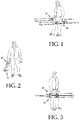
- FIG. 5 reveals a ski pole 12 with its grip 14, strap 16, and shaft 18 whose form is usually tapered as it approaches the basket 20 and pole tip 22. Because some pole systems use a detachable strap or a glove-integrated strap, many of the ski pole 12 depictions in the figures do not feature a strap. However, because all embodiments are also consistent with a strap permanently attached to the grip, some of the figures feature a strap in a position that does not interfere with the function of the invention.
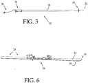
- FIG. 6 depicts a typical ski 24 whose relevant anatomy includes it upwardly bent tip 26 which is in the front of the ski, a base 30 which contacts the snow during use, a tail 28 (which includes the entire portion of the ski rear of the bindings for purposes of this patent), and a top 32 which faces up when the skis are on the snow and upon which the bindings are attached, often by a means, such as a binding track (shown here) or a channel, and sometimes screws or other means.
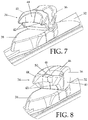
- FIGS. 7 and 8 reveal two common front binding mechanisms.
- FIG. 7 represents the most common form of front binding 34 (referred to in this patent as the "beveled" binding), which includes a toe piece 36 which is the main body of the front binding.
- the toe piece 36 usually sits upon a toe piece platform 38, which not only holds the toe piece 36 to the ski top 32 but also supports the front sole of the ski boot when in use.
- the rear of the toe piece 36 houses a toe securing abutment 40 on which is formed a toe securing lip 42, which normally lies over and secures the toe of the boot..
- the toe securing abutment 40 can move side-to-side, split open, (and sometimes move upward) to release the boot when a skier's fall applies a sufficient amount of force in the direction of the release, thereby avoiding damage to the skier's legs.
- the toe securing abutment 40 is often a combination of complex mechanics composed of many internal pieces, not relevant here.
- the amount of force necessary to cause the release is set by a ski technician based upon the skill level and weight of the skier.
- Preceding the toe securing lip is a toe guiding bevel 44 (shown here to be quite large) which can vary in width, height and angle depending on the binding brand and model.
- This bevel is normally employed by the skier to guide the toe of the boot into place when stepping into the binding.
- the toe guiding bevel 44 can be quite minimal and appear as a nearly flat top to the binding.
- Some bindings have a grouping of lips and shapes playing the roles of toe securing lip 42 and toe guiding bevel 44, and/or toe securing abutment 40.
- the skier To engage the boot, the skier usually inserts the toe of the boot under the toe securing lip of the toe piece and then pushes the heel of the boot straight down into the heel binding.
- FIG. 8 shows another popular front binding (referred to in this patent as the "shrouded" binding).
- the shrouded binding has its toe securing abutment 40 covered by a non-moving toe piece shroud 46, which has its own shroud bevel 48 and shroud lip 50 which is above the toe securing abutment 40, toe guiding bevel 44 and toe securing lip 42.
- the shroud lip 50 plays no role in securing the boot. It is a mere fortuitous result of the termination of the toe piece shroud 46.
- FIGS. 7 and 8 both front binding types are pictured in the state in which they normally house a boot. In both binding types, any temporary movement of the parts requires great force, is brief, and takes place only during a release of the boot. After a boot release, the components return immediately to their original positions shown.
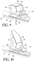
- FIG. 9 depicts the rear binding 52 in its "up" position with its parts positioned as they would be if the skier had not yet stepped into the bindings.
- the heel piece 54 rests upon the heel piece platform 56 and is usually capable of sliding rearward along the heel piece platform 56 if a rearward force is applied. The amount of force necessary to act against this spring action is usually set by a technician based upon the skill level, height, and weight of the skier.
- the heel piece platform 56 also holds a ski brake 58 (shown here in its natural braking position which engages the snow and stops the ski).
- the heel piece release lever 60 is the part which directly engages the heel of a ski boot.
- the boot engaging process is as follows: First, the skier slips the toe of the boot under the toe securing lip 42 of the front binding 34. Then, guided by the heel guiding bevel 68, the skier presses the heel downward against the heel receiving surface 62 and the heel receiving seat 64 (more clearly depicted in FIG. 10 ). The heel piece release lever 60 is forced back and down and springs into a securing position as depicted in FIG. 10 . This amount of force required to release the lever back to the up position is usually set by a technician based upon the skill level, height, and weight of the skier. The boot heel is then secured in a downward state by the heel securing lip 66.
- FIG. 10 depicts the rear binding 52 in its "down" state with the pieces positioned as they would be if a boot were engaged for skiing.
- the heel piece release lever 60 is locked down and the ski brake 58 is forced up, disengaged by the downward pressure of the boot.
- the skier usually uses the ski pole tip 22 to press down on the back portion of the heel piece release lever 60 while lifting up on the heel of the boot. This rocks the heel piece release lever 60 back and frees the boot. The skier steps out, with the resulting problem of how to pick up his skis.
- the invention takes advantage of the fact that the heel piece release lever is in the "up” position when not in use, with the ironic consequence that the bulk of its body is actually “down” and out of the way, as depicted in FIG. 9 .
- the result is two different binding groups: one binding group with a standard rear binding and a beveled front binding, and another binding group with a standard rear binding and a shrouded front binding.
- the bindings depicted are "alpine” or “touring” bindings, the invention's application is not limited to skis with alpine bindings.
- Some of the embodiments described below are suitable for use on skis with “free ride,” “down hill,” “telemark,” “cross-country,” “backcountry,” or “Nordic” bindings, as well as a variety of other binding groups, including Kandahar bindings, and other pin and cable systems.
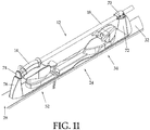
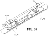
- FIG. 11 shows a basic configuration.
- the ski pole 12 is attached to the ski 24 using means of coupling which join the two in a configuration such that the grip end of the pole 12 is firmly coupled near the rear binding 52 and the forward extending pole shaft 18 is firmly coupled near the front binding 34.
- the pole 12 is in a position above the top 32 and the bindings, parallel with the ski, and extending forward. This position is unique and leaves the tail 28 of the ski clear and unencumbered.
- this particular example employs a front pole mounted base 70 and a front ski mounted base 72 to support the front means of coupling; and it uses a rear pole mounted base 74 and a rear ski mounted base 76 to support the rear means of coupling.
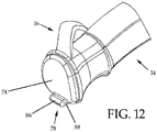
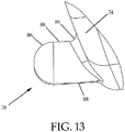
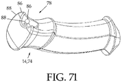
- FIGS. 12 and 13 show the detail of the particular means of coupling borne by the grip 14 of the pole 12 in this embodiment.
- a rear pole coupling formation 78 including the shape of an elongated node is borne by the rear pole mounted base 74.
- the rear pole mounted base 74 here, is in the shape of a cap, and is affixed on the top of the grip 14 just above the strap 16.
- the rear pole mounted base 74 could be affixed to the top of the grip 14 by glue or other fastening means (as a retrofit of existing poles); or it could be manufactured as a molded part of an original equipment grip.
- the rear pole coupling formation 78 could also be directly affixed to the top of a grip (serving as the rear pole mounted base 74) by a plug, dowel, or other fastening means.
- the molded rear pole mounted base 74 depicted in the figures to this patent are only illustrative of the various fastening means for the rear pole coupling formation 78 or its parent coupling means.
- the rear pole coupling formation 78 includes surfaces whose number, orientation, size and shape are sufficient to guide the formation into place (positioning surfaces 86) and surfaces whose number, orientation, size and shape are sufficient to prevent movement once the formation is in place (securing surfaces 88).
- Securing surfaces 88 and positioning surfaces 86 can overlap or be one in the same, depending on the phase of the process at the time of their identification as such. As the nature of these surfaces varies greatly and one may curve into another, or play the other's role at differing times, a line or arrow identification mark in the figures should not be considered limiting, but rather illustrative.
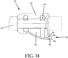
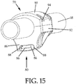
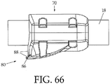
- FIGS. 14 and 15 show the detail of the particular means of attachment borne by the shaft 18 of the pole 12 in this embodiment.
- a front pole coupling formation 80 is borne by the front pole mounted base 70.
- the front pole mounted base 70 as depicted in FIGS. 14 and 15 is in the form of a top clamping piece 90 and a bottom clamping piece 92 tightened by four tightening screws 94; and as such could serve as a retrofit of existing poles (because it can be wrapped around the pole 12 without removing the grip 14 or the basket 20.
- the front pole mounted base could also be used in original equipment manufacture (OEM).
- a more convenient form for OEM might be a single piece with a single tightening screw, cam or lever, or other tightening means which may be placed over the pole before the basket or grip is affixed.
- the front pole mounted base 70 may be positioned along the shaft 18 of the pole 12 at a distance from the rear pole coupling formation 78 consistent with the distance between the coupling formations on the ski mounted bases which is in large part, determined by the length of the skier's boot.
- the front pole mounted base 70 may be incorporated into the surface of the shaft 18 or fastened to the shaft 18 by a variety of adjustable means, such as an expanding insert placed into a track built into the shaft 18 or a much smaller clamping unit placed over a rail affixed to the shaft 18.
- the clamping pieces depicted in the figures to this patent are only illustrative of the various fastening means for the front pole coupling formation 80 and its parent coupling means.
- the front pole coupling formation 80 includes the shape of an elongated node and has positioning surfaces 86 whose number, orientation, size and shape are sufficient to guide the formation into place. It also includes securing surfaces 88 whose number, orientation, size and shape are sufficient to prevent movement, once the formation is in place.
- the lower front portion of the front pole mounted base 70 also serves as part of the front pole coupling formation 80 by providing a securing surface 88 to keep the entire arrangement snug, urging the rear pole coupling formation 78 into the rear ski coupling formation 84.
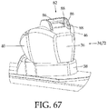
- FIG. 16 shows a detail of the rear ski mounted base 76 and the rear ski coupling formation 84 incorporated into its upper end.
- the rear ski coupling formation 84 includes positioning surfaces 86 whose number, orientation, size and shape are sufficient to guide the formation into place (here including the shape of a beveled striker) and securing surfaces 88 whose number, orientation, size and shape are sufficient to prevent movement of the coupling formations once in place (here including the shape of an elongated cavity). It should be noted that the protruded and indented nature of the positioning surfaces 86 and the securing surfaces 88 can be reversed in many cases without affecting their ability to achieve the coupling result.
- a positioning surface 86 which is a beveled striker, is oriented to allow the rear pole coupling formation 78 to be pushed down and snapped into place if the front pole coupling formation 80 and the front ski coupling formation 82 have already been fitted together.
- the securing surfaces 88 in this embodiment include an elongated cavity to compliment and contact the rear securing surfaces 88 of the rear pole coupling formation 78 at all points.
- the rear ski mounted base 76 is attached to the top 32 of the ski using an attachment means such as an adhesive or screws.
- the front ski mounted base 72 would be substantially the same as shown in FIG.11 .
- the ski mounted bases, adhesives and screws mentioned in this patent are only illustrative of the various fastening means available for the front ski coupling formation 82 and the rear ski coupling formations 84 or their parent means of attachment.
- the rear ski mounted base 76 and the front ski mounted base 72 would be constructed of a strong polymer which has some flexion, such as nylon, in order to allow some separation of the rear ski coupling formation 84 and the front ski coupling formation 82 when their positioning surfaces 86 (beveled strikers) are engaged by the elongated nodes of the rear pole coupling formation 78 and/or the front pole coupling formation 80 and a downward force is applied by the skier.
- a strong polymer which has some flexion, such as nylon, in order to allow some separation of the rear ski coupling formation 84 and the front ski coupling formation 82 when their positioning surfaces 86 (beveled strikers) are engaged by the elongated nodes of the rear pole coupling formation 78 and/or the front pole coupling formation 80 and a downward force is applied by the skier.
- Such flexion properties along with the flexion of the ski itself, would allow the front ski coupling formation 82 and the rear ski coupling formation 84 to separate sufficiently to disengage from the front pole coupling formation 80 and the rear pole coupling formation 78 when a firm pull in the reverse direction is used on the pole while securing the movement of the ski.
- Some figures describing the embodiments show features of the binding groups which act in dual capacities. In the originally intended capacity, such features are used as a means to engage and disengage a boot for the act of skiing. However, certain embodiments use these same features in a previously unimagined way: as a means to couple with a pole coupling means for the purpose of carrying the ski and pole as a single unit. When such features are shown in the drawings, two different numbers may be used to describe the same feature.
- the number (lower in denomination) indicates the originally contemplated function and its nomenclature according the list of reference numbers and the discussion of Figs 7, 8 , 9, and 10 .
- the number (higher in denomination) indicates the newly conceived function and its nomenclature according to the list of reference numbers and the discussion of the embodiment.
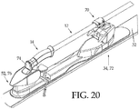
- FIGS. 17 , 18 , 19 , and 20 Another embodiment is shown in FIGS. 17 , 18 , 19 , and 20 .
- This embodiment employs the bindings as the ski mounted bases for the ski coupling means.
- the bindings play this role well, as they are already attached to the top 32 of the ski 24 in the proper orientation.
- the front binding 34 (including the toe piece shroud 46, the toe piece 36, and its supporting toe piece platform 38) serves as the front ski mounted base 72 upon which the front ski coupling formation 82 is affixed.
- the rear binding 52 (including the heel piece release lever 60, heel piece 54, and heel piece platform 56) serves as the rear ski mounted base 76 upon which the rear ski coupling formation 84 is affixed.
- the ski pole coupling means are the same in this embodiment as they are in the previous embodiment.
- the pole 12 supports a front pole mounted base 70 with a front pole coupling formation 80 in the shape of an elongated node.
- the grip 14 supports a rear pole mounted base 74 with a rear pole coupling formation 78, also in the shape of an elongated node.
- the specifics of the front pole mounted base 70, the front pole coupling formation 80, the rear pole mounted base 74 and the rear pole coupling formation 78 are also the same as in the previous embodiment.
- FIG. 18 depicts the positioning surfaces 86 and securing surfaces 88 of the rear ski coupling formation 84 as it is affixed on the top 32 of the ski 24 via the rear ski mounted base 76, which in this embodiment happens to be the rear binding 52. Also shown are the subcomponents: heel piece platform 56, the heel piece 54, and the heel piece release lever 60.
- the rear ski coupling formation 84 also includes an elongated cavity.
- the rear ski coupling formation 84 may be incorporated into the material of the heel piece release lever 60 as original equipment or may be fastened; using adhesive, welding, or other fastening means to serve as a retrofit of existing bindings.
- the positioning surfaces 86 on the rear ski coupling formation 84 are not beveled in this embodiment, the rear pole coupling formation 78 must be inserted into the rear ski coupling formation 84 first.
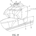
- FIG. 19 depicts the positioning surfaces 86 and securing surfaces 88 of the front ski coupling formation 82 as it is affixed on the top 32 of the ski 24 via the front binding 34 serving as the front ski mounted base 72. Shown also are the toe piece shroud 46, the toe piece 36 and the toe piece platform 38.
- the front ski coupling formation 82 includes the shape of an elongated cavity. The front ski coupling formation 82 may be incorporated into the material of the toe piece 36 or the toe piece shroud 46 as original equipment, or may be fastened using adhesive, welding, or other fastening means to serve as a retrofit of existing bindings.
- Fig 19 reveals that, in this embodiment, one of the positioning surfaces 86 on the front pole coupling formation constitutes a beveled striker, placed above the securing surfaces on said formation.
- the downward movement of the front pole coupling formation 80 into the front ski coupling formation 82 will cause the bottom front positioning surfaces 86 on the front pole coupling formation 80 to contact with the beveled striker shaped positioning surface 86 on the front ski coupling formation 82.
- Continued downward force will cause these positioning surfaces 86 to slide over one another and the resulting movement will urge the entire ski pole 12, the heel piece 54, and the heel piece release lever 60 rearward, engaging the spring action of the rear binding and creating a tight coupling as shown in FIG. 20 .
- a current embodiment utilizes the standard features on a shrouded binding (shown in FIGS. 8 and 9 ) to act as bases and coupling means for the ski 24. Thus, no separate bases or any modification of the bindings system is necessary.
- This embodiment has the advantage that only the ski pole (which is much less expensive than the binding) requires modification (as retrofit or original equipment).
- FIG. 21 depicts the placement of the rear pole coupling formation 78 into , (as opposed to on ) the heel piece release lever 60.
- rear pole coupling formation 78 into a standard heel piece release lever 60 while in the "up" position is accomplished by way of its unique shape and orientation, which resembles a "canted seat” as depicted in FIGS. 22 and 23 .
- the rear pole coupling formation 78 is affixed directly to the top portion of the handle 2 which doubles here as the rear pole mounted base 74.
- a positioning surface 86 and a securing surface 88 form a canted seat which lies above a contact avoidance recess 96.
- the contact avoidance recess 96 is instrumental in allowing the securing surface 88 and positioning surface 86 of the rear pole coupling formation 78 to reach back far enough to engage the heel piece release lever 60 properly.
- FIG. 24 shows how this embodiment creatively uses standard pole and binding parts in a manner in which such parts were never before intended to be used. It shows the rear pole coupling formation 78 mounted on the grip 14 (doubling as the rear pole mounted base 74) as it engages the heel piece release lever 60 whose front portion includes the rear ski coupling formation 84.
- the rear binding 52 performs the role of the rear ski mounted base 76 in this embodiment. Also shown are binding subcomponents (heel piece 54, the heel piece platform 56, and the heel piece release lever 60.
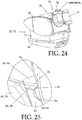
- FIG. 25 shows the detail of how the surfaces of the rear pole coupling formation 78 and the rear ski coupling formation 84 interact.
- a securing surface 88 of the rear pole coupling formation 78 lies beneath the heel securing lip 66 which also doubles as a securing surface 88 of the rear ski coupling formation 84.
- a positioning surface 86 of the rear pole coupling formation 78 rests against the heel guiding bevel 68 (more accurately shown in FIGS. 6 & 7 ) which also doubles here as a positioning surface 86 of the rear ski coupling formation 84. While the heel piece release lever 60 is in the up position, it will not accommodate a boot heel and its heel receiving surface 62 juts forward.
- the rear pole coupling formation 78 has a cleverly crafted contact avoidance recess 96 which, unlike the heel of a boot, gets out of the way, allowing positioning surfaces 86 and securing surfaces 88 of the rear pole coupling formation 78 to reach the corresponding securing surfaces 88 and positioning surfaces 86 of the rear ski coupling formation 84, which in this embodiment happen to include the heel securing lip 66, the heel guiding bevel 68, and the heel piece release lever 60, respectively.
- the rear pole coupling formation 78 could be in the form of a cap affixed to the top of the grip 14 by glue or other fastening means (as a retrofit of existing poles); or it could be manufactured as a molded part of an original equipment grip. As a retrofit the rear pole coupling formation 78 could also be directly affixed to the top of a grip by a plug, dowel, or other fastening means.
- the molded rear pole coupling formation 78 depicted in the figures here is only illustrative of the various fastening means for the rear pole coupling formation 78 or its parent coupling means.
- the front pole coupling formation 80 is likewise ingenious in that it couples with the surfaces of a standard toe piece shroud 46.
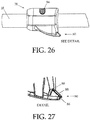
- Figs 26, 27 , and 28 depict front pole mounted base 70.
- the entire pole mounted base 70 is shown here in one piece secured by one tightening screw 94. This limits its use as a retrofit of existing poles, but has an advantage of quick, one step boot length adjustment. As stated previously, this configuration is by no means limiting.
- the clamping front pole mounted base 70 depicted in the figures to this patent is only illustrative of the various fastening means for the front pole coupling formation 80 or its parent coupling means.
- the front pole mounted base can be tightened with a single tightening screw 94, a cam or lever or other suitable tightening means. It could be an expanding plug mounted in a track cut into the pole 12, or a very small clamping unit attached to a rail on the shaft 18. It could be the shaft itself formed into the means. It could include a variety of other means to secure the front pole coupling formation 80 to the shaft 18 of the pole 12.
- FIGS. 26, 27 , and 28 also show the securing surface 88 and the positioning surface 86 in detail. Of particular note is their flat, beveled shape, making the bulk of the front pole coupling formation 80 into a beveled tooth.
- the lower front portion of the front pole mounted base 70 also serves as part of the front pole coupling formation 80 by providing a securing surface 88 to keep the entire arrangement snug, urging the rear pole coupling formation 78 into the rear ski coupling formation 84.
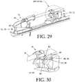
- FIG. 29 shows another view of the rear coupling of this embodiment, with the rear pole coupling formation 78 in its engaged position relative the rear ski coupling formation 84, which is on the heel piece release lever 60.
- the rear binding 52 serves as the rear ski mounted base 76.
- the heel piece release lever 60 serves as the rear ski mounted base 76.
- the heel piece 54 serves as the rear ski mounted base 76.
- the heel piece platform 56 serves as the rear ski mounted base 76.
- This figure also demonstrates how the front binding 34 forms the front ski mounted base 72.
- the toe piece shroud 46, the toe piece 36 and the toe piece platform 38 are also shown.
- FIG. 30 also demonstrates the ingenious use of the standard front binding parts in dual roles. It shows how a positioning surface 86 of the front pole coupling formation 80 (the beveled tooth depicted in figs 26-28 ) engages the shroud bevel 48 which doubles here as a positioning surface 86 of the front ski coupling formation 82 which is on the toe piece shroud 46. Upon application of downward force upon the front pole mounted base, a positioning surface 86, which is the bottom of the beveled tooth of the front pole coupling formation 80 and a positioning surface 86 (the shroud bevel 48) of the front ski coupling formation 82 slide over one another.
- disengagement of this embodiment is a snap.
- the skier simply secures the movement of the ski 24 with hand and foot and pulls on the pole 12.
- the pulling action forces the top of the beveled tooth (a securing surface 88) to slide against the shroud lip 50 (another securing surface 88) and urges the entire ski pole 12, the heel piece 54, and the heel piece release lever 60 rearward, engaging the spring action of the rear binding and moving the securing surface 88 of the beveled tooth past the shroud lip 50 and free.
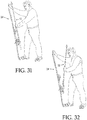
- FIG. 33 Another current embodiment is shown in FIG. 33 .
- the rear pole to ski coupling takes place in a manner identical to that of the previous embodiment. The difference is in the front coupling detailed in Fig 34 .
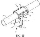
- the front pole coupling formation 80 appears as a dual toothed curvature, shown in FIG. 35 .
- This front pole coupling formation is adjustable in distance from the pole shaft 18, in order to accommodate different sizes of front bindings. This adjustability makes this embodiment a universal version, capable of coupling with the vast majority of standard beveled bindings and many shrouded bindings. Again, because poles are inexpensive to manufacture and no modification of bindings is necessary, this is an advantageous embodiment.
- FIG. 34 shows how, in this embodiment, the front binding 34 forms the front ski mounted base 72. Also shown are the toe piece 36 and the toe piece platform 38. FIG. 34 also shows the toe securing abutment 40, whose toe guiding bevel 44 and toe securing lip 42 perform the respective roles of positioning surface 86, and securing surface 88, forming the key components of the front ski coupling formation 82.
- the front pole coupling formation 80, with its positioning surfaces 86, and securing surfaces 88, includes a dual toothed curvature (described below).
- FIGS. 35 , 36 and 37 show the operative parts of the front pole coupling means.
- a front pole mounted base 70 includes a top clamping piece 90, a bottom clamping piece 92 and an extension arm 98, and supports the front pole coupling formation 80. When the front pole coupling formation 80 is in its inactive position, it is kept clamped around the shaft 18 of the ski pole 12.
- the top clamping piece 90 is connected to the bottom clamping piece 92 by way of four tightening screws 40 or other suitable fastening and tightening means. This allows its use as a retrofit of existing poles. As stated previously, this configuration is by no means limiting.
- the clamping front pole mounted base 70 depicted in the figures to this patent are only illustrative of the various fastening means for the front pole coupling formation 80 or its parent coupling means.
- the front pole mounted base can be a single piece with a single tightening screw 94, an expanding plug mounted in a track cut into the shaft 18, a very small clamp fastened to a rail affixed to the shaft 18, and/or include a variety of other means to secure the front pole coupling formation 80 to the shaft 18 of the pole 12.
- the extension arm 98 is pivotally attached to the bottom clamping piece 92 by a set screw 100, rivet, or other pivotal fastening means.
- the front pole coupling formation 80 is attached to the extension arm 98 by way of an adjustment screw 102 (or other fastening means), a lock washer 104 (or other slippage prevention means) and a hex nut 106 (or other fastening means if necessary).
- the front pole coupling formation 80 includes a dual toothed curvature and has securing surfaces 88 and positioning surfaces 86 along the lines of the bevels in each tooth. Its curvature allows it to snap around the shaft 18 when not in use, as shown in FIG. 36 .
- the entire front pole mounted base 70, and its extension arm 98 can be made of aluminum, stainless steel, or a suitably rigid polymer, such as glass infused nylon.
- the dual toothed curvature of front pole coupling formation 80 is concave and made of a softer material, such as nylon, with sufficient durability to repeatedly engage the front ski coupling formation 82, sufficient elasticity to snap around the pole 12 in its non-active position, and sufficient softness to avoid scratching the binding.
- the extension arm 98 is configured such that its furthest pivot outward is perpendicular to the pole shaft 18, as shown in FIGS. 35 and 37 .
- FIGS. 38 and 39 indicate how the skier prepares the front pole coupling formation 80 for engagement, using a finger to push the extension arm 98 downward.
- FIGs 40, 41, and 42 illustrate how the coupling of this embodiment is achieved.
- the rear pole coupling formation 78 here a "canted seat”
- the rear ski coupling formation 84 on the heel piece release lever 60
- a downward force is applied.
- the surfaces are engaged in the same manner as the previous embodiments.
- Positioning surfaces 86 of the front pole coupling formation 80 (here the bottom bevels of each tooth) will contact and slide down a positioning surface 86 (here the toe guiding bevel 44) of the front ski coupling formation 82 on the toe securing abutment 40, with the resulting movement urging the entire ski pole 12, the heel piece 54, and the heel piece release lever 60 rearward. This engages the spring action of the rear binding 52, creating a tight coupling as shown in FIG. 41 .
- the skier simply picks up the newly form pole-ski unit. The entire process takes only a few seconds. Disengagement is the same as in the previous embodiment and again may be accomplished in a few seconds.
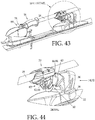
- FIG. 43 Another current embodiment operates substantially the same as the previous embodiment in that its front and rear ski based coupling means are formed by most standard binding groups, as evidenced in FIGS. 7, 8 , 9, and 10 .
- FIG. 43 its rear pole coupling means are identical to the previous two embodiments, embracing the "canted seat” concept.
- FIG. 44 demonstrates that its front pole coupling means engage the front ski coupling means in a manner identical to the previous embodiment.
- the front binding 34 forms the front ski mounted base 72. Also shown are the toe piece 36 and the toe piece platform 38.
- toe securing abutment 40 whose toe guiding bevel 44 and toe securing lip 42 perform the respective roles of positioning surface 86, and securing surface 88, forming the key components of the front ski coupling formation 82.
- FIG. 45 discloses a front pole coupling means which includes many of the same features as the previous embodiment. Included is a front pole mounted base 70, clamped onto the shaft 18 of the pole.
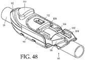
- the front pole mounted base 70 is slightly more complex and includes a top clamping piece 90, a bottom clamping piece 92, and a previously absent center clamping piece 108 (shown only in FIGS. 48 and 49 ).
- Pivotally attached to the center clamping piece 108, is an extension arm 98, which houses a similar front pole coupling formation 80.
- the front pole coupling formation 80 includes a dual toothed curvature with positioning surfaces 86 and securing surfaces 88 (shown only in FIGS. 45 and 46 ).
- the securing surface 88 which forms the top of each tooth is slanted at a much shallower angle than in previous embodiments. This helps prevent inadvertent release. This feature, along with the automatic release, makes this universal embodiment very advantageous.
- FIG. 48 shows the front pole mounted base 70 upside-down. It most accurately shows that a release lever 110 connects to a small extension arm platform 112 and the extension arm 98 exhibits an extension arm leg 114. As shown in Fig 46 , the extension arm platform 112 supports the extension arm leg 114 when the extension arm 98 is in its operative position perpendicular to the pole shaft 18. The support provided by the extension arm platform 112 in this position holds the extension arm in place at the perpendicular angle so that the front pole coupling formation 80 may engage the front ski coupling formation 82.
- FIG. 47 shows the action of the release.
- the extension arm platform 112 is also pulled back. As the arrows in FIG. 47 show this removes the support to the extension arm leg 114. As a consequence, the weight of the ski as exerted on the securing surface 88 of the front pole coupling formation 80, urges the extension arm 98 backward, as the extension arm leg 114 fills the space previously occupied by the extension arm platform 112. The ski 24 conveniently falls to the snow, base 30 down, ready for the skier to step in.
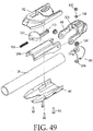
- FIG. 49 is an upside-down exploded view of the various parts of the front pole coupling means of this particular embodiment.
- Set screws 100, rivets, or other pivotally fastening means hold the extension arm 98 pivotally to the center clamping piece 108, while the dual toothed curvature included in the front pole coupling formation 80 is held to the extension arm 98 by an adjustment screw 102 (or other suitable adjusting means), a lock washer 104 (or other suitable locking means), and a hex nut 106 (or other suitable fastening means).
- the release lever 110 and its attached extension arm platform 112 are slid into and behind the bottom clamping piece 92 (from outside to inside, extension arm platform 112 first).
- the biasing means for the release leaver (not shown in previous figures) is a spring 116.
- the spring 116 is inside the front pole mounted base, which is held between the bottom clamping piece 92 and the center clamping piece 108.
- the spring 116 is situated behind the release lever 110, holding it and the extension arm platform 112 in their biased position until the release lever is pulled back by the skier's finger.
- the spring 116 also returns the release lever 110 and the extension arm platform 112 to such biased position immediately after pull back.
- the main assembly is held together by tightening screws 94 (or other suitable fastening and tightening means).
- Another current embodiment also features an automatic release means. It is smaller than the previous embodiment, but sacrifices universality, as it requires a custom front ski coupling formation 82. Its reduced size makes it highly advantageous.
- the rear coupling means are identical to the previous embodiment, using the "canted seat” version of the rear pole coupling formation 78 to engage a standard heel piece release lever 60 serving as the rear ski coupling formation 84. This is demonstrated by FIGS. 21-25 .
- the front coupling means are different. Although requiring modification, this embodiment can be incorporated into a shrouded binding easily, providing a manufacturing advantage.
- Its front pole coupling means are shown in Figs 50 and 51 . Shown there is a front pole mounted base 70 clamped to the pole shaft 18, its top clamping piece 90 and bottom clamping piece 92 held tight by fastening means such as tightening screws 94.
- the front pole mounted base could be a single piece or multiple pieces and could be incorporated into the surface of the pole or attached to it by a variety of means.
- the key to this embodiment is the front pole coupling formation 80, whose positioning surfaces 86 and securing surfaces 88 in part define a beveled bolt.
- the lower front portion of the front pole mounted base 70 also serves as part of the front pole coupling formation 80 by providing an abutment which serves as a securing surface 88 to keep the entire arrangement snug, urging the rear pole coupling formation 78 into the rear ski coupling formation 84.
- the beveled bolt portion of the front pole coupling formation 80 is retractable (back, into and behind the surface of the abutment). It is formed from the front end of the release lever 110 which (as in the previous embodiment) is held in position by a biasing means such as a spring (not shown). Its edges can be rounded to prevent snagging.
- the front pole coupling formation 80 is pushed downward toward the front ski coupling formation 82 (shown in FIG. 52 ). Then a positioning surface 86 (the bevel) on the bolt portion of the front pole coupling formation 80, first contacts a positioning surface 86 (a striker) directly above a securing surface 88 (a slot) on the front ski coupling formation 82. Upon the continued application of downward force, the bolt portion of the front ski coupling formation 82 is urged rearward against the bias. Consequently, the release lever 110 moves with it.
- the front portion of the front pole mounted base 70 contacts and continues to slide down the striker (a positioning surface 86) of the front ski coupling formation 82.
- This motion urges the rear pole coupling formation 78 into the rear ski coupling formation 84, creating a snug fit.
- This downward motion continues until the securing surface 88 which forms the top portion of the bolt reaches the securing surface 88 which forms the top portion of the slot.
- the bolt is urged forward by the biasing means, and its securing surfaces 88 slide into the slot and are consequently surrounded by the securing surfaces 88 making up slot.
- Release of the coupling is performed by using one finger to pull back on the release lever, removing the securing surfaces 88 of the bolt portion of the front pole coupling formation 80 from under the securing surfaces 88 of the slot portion of the front ski coupling formation 82.
- This causes the positioning surfaces 86 of the front pole coupling formation 80 and the front ski coupling formation 82 to slide against one another and separate. This loosens the entire coupling arrangement and the ski falls to the snow, the floor, or into the skier's hand.
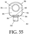
- FIGS. 54 , 55 , 56 and 57 show how merely changing the shape of the previous embodiment creates an only slightly different embodiment which is readily incorporated into a standard beveled binding. This is accomplished by altering only the curvature of some of the securing surfaces 88 and some of the positioning surfaces 86 of the front pole coupling formation 80 and the front ski coupling formation 82.
- This embodiment features a rounded beveled bolt, a rounded striker and rounded slot.
- This embodiment is also highly advantageous because of its small size and quick release. This embodiment is engaged and released in a manner identical to that of the previous embodiment.
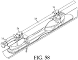
- FIG. 58 shows how the rear pole coupling means could take the form of a rear pole mounted base 74 which actually clamps to the pole 12 next to the grip 14, rather than being incorporated into or mounted on the grip 14. This embodiment could form a retrofit of poles without modification.
- rear pole mounted base 74 as shown in FIG. 58 with a rear pole coupling formation 78 in the form of a canted seat or other universal coupling means.
- Combining such rear coupling means with the front pole coupling formations 80 from the previous embodiments could form a combination that does not require the modification of the pole or the bindings, resulting in an embodiment that serves as a universal retrofit kit.
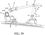
- FIG. 59 shows how by altering the shape of the positioning surfaces 86 and securing surfaces 88 of the rear ski coupling formation 84 to form a cup, one can avoid the modification of the pole handle, which itself becomes the rear pole coupling formation 78 with its rounded positioning surfaces 86 and securing surfaces 88.
- modification of the pole shaft may be avoided by the use of a front pole mounted base 70.
- the front pole mounted base 70 is a simple collar, the front edge of which combines with the surface of the pole shaft 18 to form the necessary positioning surfaces 86 and securing surfaces 88 of the front pole coupling formation 80.
- the front ski coupling formation 82 is in the form of a clamp, the positioning surfaces 86 of which help center the pole.
- the skier first places the pole handle 2 into the cup, then after a downward force is applied to the shaft of the pole near the front pole coupling means, the pole is snapped into place.
- the securing surfaces 88 of the clamp hold the shaft 18 down, and, in combination with the front edge of the collar, keep the pole 12 from sliding forward and out of the cup.
- the clamp may be made of a material which provides the requisite flexion of the securing and positioning surfaces, such as nylon, or other tensile polymer. A sharp pull in the reverse direction disengages.
- the four coupling formations can be incorporated into or mounted upon separate ski mounted bases or can incorporated into or mounted on the bindings (shown in FIG. 59 ) which can perform as ski mounted bases.
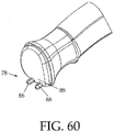
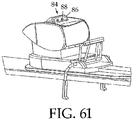
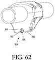
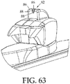
- FIGS. 60 , 61 , 62 , and 63 show an example which illustrates how the number, size, shape and orientation of the positioning surfaces 86 and securing surfaces 88 can differ.
- two points of securement are supplied by connecting two nodes (that perform the role of the rear pole coupling formation 78, its positioning surfaces 86, and securing surfaces 88) with two cavities (that perform the role of the rear ski coupling formation 84, and its positioning surfaces 86 and securing surfaces 88).
- the nodes and cavities are small, the distance between them creates the necessary stability, substituting for the width of a single surface as utilized by previous examples.
- the rear coupling formations are placed together and the front pole coupling formation 80 is pressed down into the front ski coupling formation 82.
- a single node can perform the role of the front pole coupling formation 80, its positioning surfaces 86, and securing surfaces 88.
- a single cavity and a striker can perform the role of the securing surface 88 and positioning surface 86 of front ski coupling formation 82.
- Each node-cavity combination provides only a single practical point of securement. However, in the combination shown, they work together to control all modes of directional and rotational motion of the ski-pole unit. This is because at least 3 points of connection between the securing surfaces 88 of the pole coupling formations and the securing surfaces 88 of the ski coupling formations are all that is theoretically required. This trinity provides the necessary support, stability, and guidance for the coupling.
- the three points of securement created by the front and rear coupling formations could be reoriented to place two in the front and one in the rear or two on one side and one on the other side.
- This example is demonstrative of the wide array of possible permutations of the securing surfaces 88 and positioning surfaces 86 of the coupling formations, so long as their size, orientation, number and shape are sufficient to create a rigid coupling.
- FIG. 64 shows a grip 14 serving as a rear pole mounted base 74 supporting a front facing tongue which serves as part of the rear pole coupling formation 78 and its positioning surfaces 86 and securing surfaces 88.
- the grip 14 can be made of a compressible rubberized polymer to allow compression of the rear pole mounted base 74.
- FIG. 65 shows a rear binding 52 acting as a rear ski mounted base 76 which is shown supporting a recess with a rear facing beveled lip serving as the rear ski coupling formation 84 and its positioning surfaces 86 and securing surfaces 88. Also shown are sub parts (heel piece release lever 60, a heel piece 54, and a heel piece platform 56) of the rear binding 52.
- FIG. 66 shows a front pole mounted base 70 supporting securing surfaces 88 and positioning surfaces 86 that form a rear facing beveled tooth.
- This front pole coupling formation 80 has smaller bevels than shown in previous examples. This is because this example relies solely on the compressibility of the grip material and the natural flexion of the ski to create the movement necessary to engage the coupling and the pressure required to hold the coupling together.
- the smaller bevels accommodate this limited range of motion, which is substantially less than the longer range of motion created by the spring action of the rear binding 52, or by the flexion of longer plastic ski mounted bases as utilized by previous examples.
- This example could employ the longer ski mounted flexible bases rather than bindings (which would allow for longer beveled surfaces).
- FIG. 67 shows a front binding 34 in the role of front ski mounted base 72 which is supporting a front ski coupling formation 82 which includes a front facing striker as a positioning surface 86 and a front facing slot as securing surfaces 88. Also shown are the subparts of the front binding 34 (toe piece platform 38, a toe piece 36, and a toe piece shroud 46, and toe securing abutment 40).
- the grip 14 which supports the tongue compressed and the rear facing beveled tooth snaps into the front facing slot, creating a firm coupling as shown in FIG. 68 . Disengagement is accomplished by pulling in the reverse direction.
- FIG. 69 illustrates an example which uses a ball and socket approach.
- the coupling is achieved by pressing both the front pole coupling formation 80 and the rear pole coupling formation 78 onto the front ski coupling formation 82 and rear ski coupling formation 84 at the same time.
- the front binding 34 and the rear binding 52 again serve as the front ski mounted base 72 and the rear ski mounted base 76, respectively.
- the coupling force is achieved by the socket compressing around the ball.
- FIG. 70 shows the front ski coupling formation 82 which includes side flanges and a socket which serve as the securing surfaces 88 and positioning surfaces 86.
- FIG. 71 illustrates the grip 14 which serves simultaneously as the rear pole mounted base 74.
- the edges of the grip 14, and a recess in the grip 14 to which a ball is attached, as well as the ball, combine to serve as the rear pole coupling formation 78 whose securing surfaces 88 and positioning surfaces 86 are, for the most part, identified in the illustration.
- FIG. 72 illustrates the joining of the front pole coupling formation 80 and the front ski coupling formation 82.
- the rear coupling is achieved in substantially the same manner. Disengagement of the couplings is achieved by pulling upward on the front and rear couplings at the same time.
- the ball and socket positions could be reversed from ski mounted to pole mounted and vice-versa.
- FIG. 73 Another pole neutral example is shown in FIG. 73 .
- This example is substantially the same as the previous example with the exception that the ball and socket portions of the front pole coupling formation 80, the rear pole coupling formation 78, the front ski coupling formation 82, and the rear ski coupling formation 84, have each been replace by strongly attractive industrial magnets.
- a variety of pole neutral examples can be envisioned. These would involve coupling formations (front pole coupling formation 80, rear pole coupling formation 78, front ski coupling formation 82, and rear ski coupling formation 84) whose securing surfaces 88 and positioning surfaces 86, in part embody a coupling means selected from the group consisting of, catches, clips, fasteners and snaps. Those skilled in the art will readily recognize that a variety of conventional coupling means can be employed.
- FIG. 74 shows a rear pole coupling formation 78 in the form of a canted seat and a rear ski coupling formation 84 in the form of a heel piece release lever 60.
- FIG. 74 shows a rear pole coupling formation 78 in the form of a canted seat and a rear ski coupling formation 84 in the form of a heel piece release lever 60.
- These rear coupling features are combined with the coupling features of the previous example (a front pole coupling formation 80 which includes a ball and a front ski coupling formation 82 which includes a socket).
- FIG. 75 shows an example in which an elongated clamp serving as a single ski coupling formation 118 (and its positioning surfaces 86 and securing surfaces 88) is incorporated into the front binding 34 which serves simultaneously as a single ski mounted base 122.
- the elongated clamp which serves as the only ski coupling formation 118 can be made of a polymer such as nylon, or other sufficiently flexible but rigid material.
- any suitable sturdy material such as aluminum, stainless steel, magnesium, titanium or other metal or nylon, glass infused nylon, various polymers, composites, carbon fibers, or other plastic of sufficient hardness, rigidity and tensile properties for the intended function, may be used instead of the materials described earlier.
- any arrangement of positioning surfaces 86 and securing surfaces 88 regardless of how flat or how sharp, how acutely or obtusely angled, how rounded or flattened, may suffice to create the coupling.
- any configuration of pole coupling formations no matter how close together or far apart, no matter how affixed to, or incorporated into, the ski 24 and/or pole 12, now matter how oriented (facing front, rear, side, down or up) may suffice to create equivalent functions to those illustrated in the drawings.
Landscapes
- Fittings On The Vehicle Exterior For Carrying Loads, And Devices For Holding Or Mounting Articles (AREA)
- Footwear And Its Accessory, Manufacturing Method And Apparatuses (AREA)
Claims (3)
- Integrierte Stock-zu-Ski-Kupplungsanordnung zum lösbaren und starren Verbinden eines Skistocks (12) mit einem Ski (24), umfassend:- eine Bindungsgruppe mit einem Zehenteil (36) und einem Fersenteil (54),- eine hintere Skikupplungsstruktur (84), die am Fersenteil (54) der Bindungsgruppe befestigt oder darin integriert ist;- eine hintere Stockkupplungsstruktur (78), die dazu dient, an einem Griff (14) eines Skistocks (12) befestigt zu werden und die dazu dient, den Skistock (12) lösbar mit der hinteren Skikupplungsstruktur (84) zu verbinden, wobei die hintere Stockkupplungsstruktur (78) eine am Stock montierte hintere Basis (74) umfasst und die am Stock montierte hintere Basis (74) einen ersten längliche Vorsprung (78) umfasst, und wobei die hintere Skikupplungsstruktur (84) eine am Ski montierte hintere Basis (76) und einen ersten länglichen Hohlraum (88) umfasst;- eine vordere Stockkupplungsstruktur (80), die dazu dient, am Skistock (12) befestigt zu werden, wobei die vordere Stockkupplungsstruktur (80) eine am Stock montierte vordere Basis (70) und einen zweiten länglichen Vorsprung (86) umfasst; und- eine vordere Skikupplungsstruktur (82), die am Zehenteil (36) der Bindungsgruppe befestigt oder darin integriert ist, wobei die vordere Stockkupplungsstruktur (80) dazu dient, an einem Schaft (18) des Skistocks (12) befestigt zu werden, wobei die vordere Stockkupplungsstruktur (82) einen zweiten länglichen Hohlraum (88) umfasst, wobei die Vorsprünge (78, 96) und die Hohlräume (88) eine Schnappverbindung zum festen Verkoppeln des Skistocks mit dem Ski bilden;
wobei ein hinterer Teil (28) des Skis, der sich im Wesentlichen von einer Rückseite des Fersenteils (54) zu einer Rückseite des Skis erstreckt, frei und unbelastet ist, wenn die hintere Stockkupplungsstruktur (78) und die hintere Skikupplungsstruktur (84) verkoppelt sind, um den Skistock lösbar und starr mit dem Ski zu verbinden. - Kupplungsanordnung nach Anspruch 1, wobei die am Stock montierte hintere Basis (76) am Griff (14) fixiert ist.
- Kupplungsanordnung nach Anspruch 2, wobei der Griff (14) eine Schlaufe (16) umfasst, wobei die am Stock montierte hintere Basis (76) als Kappe ausgebildet ist, die an der Oberseite des Griffs (14) fixiert ist, und wobei die Kappe oberhalb der Schlaufe (16) fixiert ist.
Applications Claiming Priority (3)
| Application Number | Priority Date | Filing Date | Title |
|---|---|---|---|
| US6906408P | 2008-03-12 | 2008-03-12 | |
| US12/402,383 US8235423B2 (en) | 2008-03-12 | 2009-03-11 | Integrated pole-to-ski coupling arrangement |
| PCT/US2009/036957 WO2009114690A1 (en) | 2008-03-12 | 2009-03-12 | Integrated pole-to-ski coupling arrangement |
Publications (3)
| Publication Number | Publication Date |
|---|---|
| EP2268370A1 EP2268370A1 (de) | 2011-01-05 |
| EP2268370A4 EP2268370A4 (de) | 2012-09-19 |
| EP2268370B1 true EP2268370B1 (de) | 2019-11-06 |
Family
ID=41062199
Family Applications (1)
| Application Number | Title | Priority Date | Filing Date |
|---|---|---|---|
| EP09720287.3A Active EP2268370B1 (de) | 2008-03-12 | 2009-03-12 | Integrierte anordnung zur koppelung eines skistocks an einen ski |
Country Status (7)
| Country | Link |
|---|---|
| US (2) | US8235423B2 (de) |
| EP (1) | EP2268370B1 (de) |
| CN (1) | CN102083506A (de) |
| CA (1) | CA2755179A1 (de) |
| EA (1) | EA201001480A1 (de) |
| NZ (1) | NZ588078A (de) |
| WO (1) | WO2009114690A1 (de) |
Families Citing this family (13)
| Publication number | Priority date | Publication date | Assignee | Title |
|---|---|---|---|---|
| FR2910337B1 (fr) * | 2006-12-20 | 2009-06-05 | Salomon Sa | Article comprenant un bouton mobile entre au moins deux positions |
| US8915382B2 (en) * | 2009-09-15 | 2014-12-23 | Peter Totman | Apparatus and system for supporting a ski |
| US8371614B2 (en) * | 2010-05-28 | 2013-02-12 | Joseph Judethaddeus Rodriguez | Ski-pole coupling assembly |
| US9126100B2 (en) | 2013-09-24 | 2015-09-08 | Joseph C. Spehar | Ski training apparatus |
| USD717897S1 (en) | 2013-09-24 | 2014-11-18 | Joseph C. Spehar | Ski training apparatus |
| WO2017035561A1 (en) * | 2015-09-03 | 2017-03-09 | Owen Kent | Connectable ski poles |
| WO2017223410A1 (en) * | 2016-06-24 | 2017-12-28 | Vacovec John | Ski pole locking system and methods of use for carrying skis |
| US10471332B2 (en) * | 2017-01-18 | 2019-11-12 | Joan Scheingraber | Ski binding rescue device |
| IT201700028741A1 (it) * | 2017-03-15 | 2018-09-15 | Flavio Bernocchi | Dispositivo per l'accoppiamento fra un guanto ed un bastone per pratica sportiva |
| CN108309075A (zh) * | 2018-04-07 | 2018-07-24 | 张红卫 | 一种便携收纳式户外烧烤炉 |
| US20200206599A1 (en) * | 2018-12-26 | 2020-07-02 | Darin Mich'l | Folding and collapsible snowboard pole mounting system |
| US11731030B2 (en) | 2021-02-18 | 2023-08-22 | Lloyd A. Marks | Releasable magnetic ski pole strap system |
| DE102023100330B4 (de) * | 2023-01-09 | 2024-12-12 | Ulrich Bergmeier | Skistock mit Magneteinheit zum Befestigen an einem Ski |
Family Cites Families (60)
| Publication number | Priority date | Publication date | Assignee | Title |
|---|---|---|---|---|
| US3337226A (en) * | 1964-10-09 | 1967-08-22 | Kato Koji | Shoe binding fixture for skis |
| DE1578728A1 (de) * | 1967-08-17 | 1971-11-04 | Franz Brueckl | Sicherheits-Skistock |
| US3623622A (en) * | 1970-07-13 | 1971-11-30 | Westhem Corp Ltd | Safety locking closure |
| US3687472A (en) * | 1970-07-20 | 1972-08-29 | Arthur D Struble Jr | Ski concept |
| US3747815A (en) * | 1971-12-06 | 1973-07-24 | M Ettl | Ski carrier |
| US3917137A (en) * | 1974-03-14 | 1975-11-04 | Douglas S Wilkins | Ski equipment carrying apparatus |
| US4181321A (en) * | 1974-03-15 | 1980-01-01 | S.A. Etablissements | Combined ski brake and fastening device |
| US3941397A (en) * | 1974-06-17 | 1976-03-02 | Kidder Richard A | Ski device |
| US4002349A (en) * | 1975-11-24 | 1977-01-11 | Dopp Kip H | Ski clip device |
| CH607617A5 (de) * | 1976-03-30 | 1978-09-29 | Karl Boesch | |
| DE2616431A1 (de) * | 1976-04-14 | 1977-10-27 | Eberhard Loeffelholz | Stock fuer ski o.dgl. sportbretter sowie mit diesem zusammenfuegbarer ski |
| US4040551A (en) * | 1976-06-02 | 1977-08-09 | Brumbaugh Andrew L | Ski and ski pole carrier |
| US4175683A (en) * | 1977-03-31 | 1979-11-27 | Shields Michael P | Ski pole basket and carrying assembly |
| US4247132A (en) * | 1978-03-15 | 1981-01-27 | Shields Michael P | Ski pole |
| US4190182A (en) * | 1978-02-17 | 1980-02-26 | Ski Tree, Inc. | Ski carrier |
| US4165027A (en) * | 1978-02-21 | 1979-08-21 | Briggs Robert W | Ski and ski pole assembly |
| US4364585A (en) * | 1978-03-15 | 1982-12-21 | Shields Michael P | Ski pole |
| DE2834948A1 (de) * | 1978-07-27 | 1980-02-21 | Jutzi Geb Schott Erika | Skifangseil auch zum tragen des skis zusammen mit einem skistock geeignet |
| US4261493A (en) * | 1979-11-28 | 1981-04-14 | Newman Marilyn L | Carrying and locking strap for skis and poles |
| US4361347A (en) * | 1980-07-21 | 1982-11-30 | Macintyre Robert W | Ski pole basket carrier system |
| US4377306A (en) * | 1981-08-24 | 1983-03-22 | Abatecola Diana P | Ski and ski pole tote |
| US4494787A (en) * | 1983-07-25 | 1985-01-22 | Gainey Michael D | Foldable ski and pole carrier |
| AT381642B (de) * | 1985-02-15 | 1986-11-10 | Tyrolia Freizeitgeraete | Durch skibremsen gebildete vorrichtung zum zusammenhalten eines skipaares |
| US4588115A (en) * | 1985-03-11 | 1986-05-13 | Uyeda Mark H | Ski and ski pole carrier and snow scraper |
| US4702495A (en) * | 1985-08-02 | 1987-10-27 | Roda Gary E | Ski pole receiver |
| US4630842A (en) * | 1985-08-02 | 1986-12-23 | Roda Gary E | Method and apparatus for carrying snow skis |
| US5015005A (en) * | 1986-06-05 | 1991-05-14 | Marker Deutschland Gmbh | Front-piece for a safety ski-binding |
| US4729591A (en) * | 1986-06-18 | 1988-03-08 | Scalise Ronald J | Combination ski, ski pole and ski boot carrying strap |
| US4750760A (en) * | 1987-01-05 | 1988-06-14 | Gurley Mark L | Ski pole grip |
| US4793627A (en) * | 1987-07-06 | 1988-12-27 | Monreal F Javier | Ski handles convertible to standard ski poles |
| US4786097A (en) * | 1987-11-05 | 1988-11-22 | Nancy J. Cornett | Ski and ski pole carrying handle |
| FR2623096B1 (fr) * | 1987-11-18 | 1990-02-23 | Salomon Sa | Fixation de securite de ski alpin |
| US4861072A (en) * | 1988-07-19 | 1989-08-29 | Humphrey Lloyd E | Apparatus and method for carrying skis and ski poles |
| US4852931A (en) * | 1988-10-31 | 1989-08-01 | Ferdi Allan W | Ski and pole carrier |
| DE8902049U1 (de) * | 1989-02-21 | 1990-04-05 | Marker Deutschland GmbH, 8116 Eschenlohe | Skibremsenpaar für ein Paar Ski |
| US4953892A (en) * | 1989-04-21 | 1990-09-04 | Adkins Keith W | Ski pole clip |
| US5141251A (en) * | 1990-07-20 | 1992-08-25 | Smith Herbert R | Ski pole clip attachment to skis for carrying |
| US5160074A (en) * | 1991-09-16 | 1992-11-03 | Coates Douglas L | Ski sling |
| US5228633A (en) * | 1992-02-03 | 1993-07-20 | Motorola, Inc. | Paper roll holder and method |
| US5350096A (en) | 1992-06-03 | 1994-09-27 | Advanced Pro-Formance, Inc. | Ski carrier |
| GB9311628D0 (en) | 1993-06-04 | 1993-07-21 | Burr David F | Improvements in ski carrying straps |
| US5468036A (en) * | 1994-02-14 | 1995-11-21 | Brown; Ronny W. | Ski and ski pole transport strap system |
| US5951047A (en) * | 1997-01-03 | 1999-09-14 | Dungan; D. Patrick | Locking and carrying system for ski equipment |
| US6347808B1 (en) * | 1998-04-24 | 2002-02-19 | Daryl Pennington | Skicup attached to a ski binding |
| US6217073B1 (en) * | 1998-09-16 | 2001-04-17 | Paul Hoffman | Collapsible snow pole |
| US6345843B1 (en) * | 1999-06-28 | 2002-02-12 | Keith M. Barnes | Snow board with collapsible ski poles and holders for same |
| EP1238687A3 (de) | 2000-07-19 | 2003-04-02 | Rudolf Geyermann | Skiträgersystem |
| US7273233B2 (en) | 2002-05-03 | 2007-09-25 | Kerstin Moller | Ski clip |
| GB0226225D0 (en) * | 2002-11-09 | 2002-12-18 | Rolf Nigel G | A ski carrying device |
| US20050015933A1 (en) * | 2003-07-25 | 2005-01-27 | Tom Hasegawa | Removable handles for cooking vessels and cooking vessels using same |
| AT500306B1 (de) * | 2003-08-06 | 2008-09-15 | Atomic Austria Gmbh | Bremsvorrichtung für einen schi |
| US7272233B2 (en) * | 2003-09-11 | 2007-09-18 | Clarity Technologies, Inc. | Acoustic shock prevention |
| DK176011B1 (da) * | 2004-04-14 | 2005-11-28 | Jesper Erichsen | Skiholder |
| US7658413B2 (en) * | 2004-07-02 | 2010-02-09 | Andon Malone | Retractable snow pole and snowboard binding combination |
| US7568599B2 (en) * | 2004-10-12 | 2009-08-04 | Julie Hall | Ski tote including a backpack strap for carrying a pair of skis |
| GB2428562A (en) * | 2005-07-22 | 2007-02-07 | Kariski Ltd | Device for carrying a pair of skis |
| US7490858B1 (en) * | 2005-10-17 | 2009-02-17 | David R. Sellers | Sports equipment transport apparatus |
| US7798528B2 (en) * | 2005-10-17 | 2010-09-21 | David R. Sellers | Sports equipment transport apparatus |
| USD529567S1 (en) * | 2005-11-15 | 2006-10-03 | Bishop Philip E | Support bracket for snow board pole |
| DE202006009008U1 (de) * | 2006-06-08 | 2006-08-17 | Sperlich, Charlie | Trageanordnung zum gemeinsamen Transport von Skistöcken und Skiern |
-
2009
- 2009-03-11 US US12/402,383 patent/US8235423B2/en not_active Expired - Fee Related
- 2009-03-12 CN CN2009801170628A patent/CN102083506A/zh active Pending
- 2009-03-12 NZ NZ588078A patent/NZ588078A/en not_active IP Right Cessation
- 2009-03-12 EA EA201001480A patent/EA201001480A1/ru unknown
- 2009-03-12 EP EP09720287.3A patent/EP2268370B1/de active Active
- 2009-03-12 WO PCT/US2009/036957 patent/WO2009114690A1/en not_active Ceased
- 2009-03-12 CA CA2755179A patent/CA2755179A1/en not_active Abandoned
-
2012
- 2012-07-09 US US13/544,272 patent/US20130168952A1/en not_active Abandoned
Non-Patent Citations (1)
| Title |
|---|
| None * |
Also Published As
| Publication number | Publication date |
|---|---|
| US8235423B2 (en) | 2012-08-07 |
| CN102083506A (zh) | 2011-06-01 |
| EA201001480A1 (ru) | 2011-04-29 |
| EP2268370A4 (de) | 2012-09-19 |
| EP2268370A1 (de) | 2011-01-05 |
| WO2009114690A1 (en) | 2009-09-17 |
| NZ588078A (en) | 2014-03-28 |
| US20090230667A1 (en) | 2009-09-17 |
| US20130168952A1 (en) | 2013-07-04 |
| CA2755179A1 (en) | 2009-09-17 |
Similar Documents
| Publication | Publication Date | Title |
|---|---|---|
| EP2268370B1 (de) | Integrierte anordnung zur koppelung eines skistocks an einen ski | |
| US5762242A (en) | Ski carrying system | |
| US5425485A (en) | Boot connecting and carrying strap | |
| US5516150A (en) | Ski glove/grip interlock system | |
| US5653455A (en) | Skiing sled and harness | |
| US4852931A (en) | Ski and pole carrier | |
| US20080185409A1 (en) | Sports board carrying device | |
| US20180193719A1 (en) | Carrying ski equipment | |
| US6510764B2 (en) | Automatically tightening pedal strap | |
| US8905275B1 (en) | Alpine ski and snowboard carrying device | |
| US7201401B1 (en) | Collapsible snowboarder pole | |
| EP4247505B1 (de) | Verbindungssystem für einen skistock | |
| JP7387621B2 (ja) | スノースキー装備の固定デバイス | |
| EP3204130B1 (de) | Hebegurtträger für skis und skischuhe | |
| US20020084624A1 (en) | Ski system | |
| US8556296B2 (en) | Miniature ski tote | |
| US20050199660A1 (en) | Ski carrying device | |
| US20070235478A1 (en) | User Portable Object-Holder | |
| EP2396092A1 (de) | Transportartikel mit rädern | |
| JP3208687U (ja) | 繋ぎ縄装置 | |
| WO1993015798A1 (en) | Device for carrying skis and ski poles together | |
| CA2253772A1 (en) | Ski sling | |
| CA2733843A1 (en) | Retractable footwear carrying device | |
| GB2485860A (en) | Ski carrying apparatus |
Legal Events
| Date | Code | Title | Description |
|---|---|---|---|
| PUAI | Public reference made under article 153(3) epc to a published international application that has entered the european phase |
Free format text: ORIGINAL CODE: 0009012 |
|
| 17P | Request for examination filed |
Effective date: 20101012 |
|
| AK | Designated contracting states |
Kind code of ref document: A1 Designated state(s): AT BE BG CH CY CZ DE DK EE ES FI FR GB GR HR HU IE IS IT LI LT LU LV MC MK MT NL NO PL PT RO SE SI SK TR |
|
| AX | Request for extension of the european patent |
Extension state: AL BA RS |
|
| DAX | Request for extension of the european patent (deleted) | ||
| A4 | Supplementary search report drawn up and despatched |
Effective date: 20120820 |
|
| RIC1 | Information provided on ipc code assigned before grant |
Ipc: A63C 11/02 20060101AFI20120813BHEP |
|
| 17Q | First examination report despatched |
Effective date: 20140411 |
|
| STAA | Information on the status of an ep patent application or granted ep patent |
Free format text: STATUS: EXAMINATION IS IN PROGRESS |
|
| GRAP | Despatch of communication of intention to grant a patent |
Free format text: ORIGINAL CODE: EPIDOSNIGR1 |
|
| STAA | Information on the status of an ep patent application or granted ep patent |
Free format text: STATUS: GRANT OF PATENT IS INTENDED |
|
| INTG | Intention to grant announced |
Effective date: 20181205 |
|
| GRAS | Grant fee paid |
Free format text: ORIGINAL CODE: EPIDOSNIGR3 |
|
| GRAA | (expected) grant |
Free format text: ORIGINAL CODE: 0009210 |
|
| STAA | Information on the status of an ep patent application or granted ep patent |
Free format text: STATUS: THE PATENT HAS BEEN GRANTED |
|
| AK | Designated contracting states |
Kind code of ref document: B1 Designated state(s): AT BE BG CH CY CZ DE DK EE ES FI FR GB GR HR HU IE IS IT LI LT LU LV MC MK MT NL NO PL PT RO SE SI SK TR |
|
| REG | Reference to a national code |
Ref country code: GB Ref legal event code: FG4D |
|
| REG | Reference to a national code |
Ref country code: CH Ref legal event code: EP Ref country code: AT Ref legal event code: REF Ref document number: 1197980 Country of ref document: AT Kind code of ref document: T Effective date: 20191115 |
|
| REG | Reference to a national code |
Ref country code: DE Ref legal event code: R096 Ref document number: 602009060351 Country of ref document: DE |
|
| REG | Reference to a national code |
Ref country code: IE Ref legal event code: FG4D |
|
| REG | Reference to a national code |
Ref country code: NL Ref legal event code: MP Effective date: 20191106 |
|
| REG | Reference to a national code |
Ref country code: LT Ref legal event code: MG4D |
|
| PG25 | Lapsed in a contracting state [announced via postgrant information from national office to epo] |
Ref country code: LV Free format text: LAPSE BECAUSE OF FAILURE TO SUBMIT A TRANSLATION OF THE DESCRIPTION OR TO PAY THE FEE WITHIN THE PRESCRIBED TIME-LIMIT Effective date: 20191106 Ref country code: SE Free format text: LAPSE BECAUSE OF FAILURE TO SUBMIT A TRANSLATION OF THE DESCRIPTION OR TO PAY THE FEE WITHIN THE PRESCRIBED TIME-LIMIT Effective date: 20191106 Ref country code: NL Free format text: LAPSE BECAUSE OF FAILURE TO SUBMIT A TRANSLATION OF THE DESCRIPTION OR TO PAY THE FEE WITHIN THE PRESCRIBED TIME-LIMIT Effective date: 20191106 Ref country code: LT Free format text: LAPSE BECAUSE OF FAILURE TO SUBMIT A TRANSLATION OF THE DESCRIPTION OR TO PAY THE FEE WITHIN THE PRESCRIBED TIME-LIMIT Effective date: 20191106 Ref country code: ES Free format text: LAPSE BECAUSE OF FAILURE TO SUBMIT A TRANSLATION OF THE DESCRIPTION OR TO PAY THE FEE WITHIN THE PRESCRIBED TIME-LIMIT Effective date: 20191106 Ref country code: BG Free format text: LAPSE BECAUSE OF FAILURE TO SUBMIT A TRANSLATION OF THE DESCRIPTION OR TO PAY THE FEE WITHIN THE PRESCRIBED TIME-LIMIT Effective date: 20200206 Ref country code: FI Free format text: LAPSE BECAUSE OF FAILURE TO SUBMIT A TRANSLATION OF THE DESCRIPTION OR TO PAY THE FEE WITHIN THE PRESCRIBED TIME-LIMIT Effective date: 20191106 Ref country code: PL Free format text: LAPSE BECAUSE OF FAILURE TO SUBMIT A TRANSLATION OF THE DESCRIPTION OR TO PAY THE FEE WITHIN THE PRESCRIBED TIME-LIMIT Effective date: 20191106 Ref country code: GR Free format text: LAPSE BECAUSE OF FAILURE TO SUBMIT A TRANSLATION OF THE DESCRIPTION OR TO PAY THE FEE WITHIN THE PRESCRIBED TIME-LIMIT Effective date: 20200207 Ref country code: NO Free format text: LAPSE BECAUSE OF FAILURE TO SUBMIT A TRANSLATION OF THE DESCRIPTION OR TO PAY THE FEE WITHIN THE PRESCRIBED TIME-LIMIT Effective date: 20200206 Ref country code: PT Free format text: LAPSE BECAUSE OF FAILURE TO SUBMIT A TRANSLATION OF THE DESCRIPTION OR TO PAY THE FEE WITHIN THE PRESCRIBED TIME-LIMIT Effective date: 20200306 |
|
| PG25 | Lapsed in a contracting state [announced via postgrant information from national office to epo] |
Ref country code: HR Free format text: LAPSE BECAUSE OF FAILURE TO SUBMIT A TRANSLATION OF THE DESCRIPTION OR TO PAY THE FEE WITHIN THE PRESCRIBED TIME-LIMIT Effective date: 20191106 Ref country code: IS Free format text: LAPSE BECAUSE OF FAILURE TO SUBMIT A TRANSLATION OF THE DESCRIPTION OR TO PAY THE FEE WITHIN THE PRESCRIBED TIME-LIMIT Effective date: 20200306 |
|
| PG25 | Lapsed in a contracting state [announced via postgrant information from national office to epo] |
Ref country code: CZ Free format text: LAPSE BECAUSE OF FAILURE TO SUBMIT A TRANSLATION OF THE DESCRIPTION OR TO PAY THE FEE WITHIN THE PRESCRIBED TIME-LIMIT Effective date: 20191106 Ref country code: RO Free format text: LAPSE BECAUSE OF FAILURE TO SUBMIT A TRANSLATION OF THE DESCRIPTION OR TO PAY THE FEE WITHIN THE PRESCRIBED TIME-LIMIT Effective date: 20191106 Ref country code: DK Free format text: LAPSE BECAUSE OF FAILURE TO SUBMIT A TRANSLATION OF THE DESCRIPTION OR TO PAY THE FEE WITHIN THE PRESCRIBED TIME-LIMIT Effective date: 20191106 Ref country code: EE Free format text: LAPSE BECAUSE OF FAILURE TO SUBMIT A TRANSLATION OF THE DESCRIPTION OR TO PAY THE FEE WITHIN THE PRESCRIBED TIME-LIMIT Effective date: 20191106 |
|
| REG | Reference to a national code |
Ref country code: DE Ref legal event code: R097 Ref document number: 602009060351 Country of ref document: DE |
|
| REG | Reference to a national code |
Ref country code: AT Ref legal event code: MK05 Ref document number: 1197980 Country of ref document: AT Kind code of ref document: T Effective date: 20191106 |
|
| PG25 | Lapsed in a contracting state [announced via postgrant information from national office to epo] |
Ref country code: SK Free format text: LAPSE BECAUSE OF FAILURE TO SUBMIT A TRANSLATION OF THE DESCRIPTION OR TO PAY THE FEE WITHIN THE PRESCRIBED TIME-LIMIT Effective date: 20191106 |
|
| PLBE | No opposition filed within time limit |
Free format text: ORIGINAL CODE: 0009261 |
|
| STAA | Information on the status of an ep patent application or granted ep patent |
Free format text: STATUS: NO OPPOSITION FILED WITHIN TIME LIMIT |
|
| REG | Reference to a national code |
Ref country code: DE Ref legal event code: R119 Ref document number: 602009060351 Country of ref document: DE |
|
| 26N | No opposition filed |
Effective date: 20200807 |
|
| PG25 | Lapsed in a contracting state [announced via postgrant information from national office to epo] |
Ref country code: MC Free format text: LAPSE BECAUSE OF FAILURE TO SUBMIT A TRANSLATION OF THE DESCRIPTION OR TO PAY THE FEE WITHIN THE PRESCRIBED TIME-LIMIT Effective date: 20191106 |
|
| REG | Reference to a national code |
Ref country code: CH Ref legal event code: PL |
|
| PG25 | Lapsed in a contracting state [announced via postgrant information from national office to epo] |
Ref country code: SI Free format text: LAPSE BECAUSE OF FAILURE TO SUBMIT A TRANSLATION OF THE DESCRIPTION OR TO PAY THE FEE WITHIN THE PRESCRIBED TIME-LIMIT Effective date: 20191106 Ref country code: AT Free format text: LAPSE BECAUSE OF FAILURE TO SUBMIT A TRANSLATION OF THE DESCRIPTION OR TO PAY THE FEE WITHIN THE PRESCRIBED TIME-LIMIT Effective date: 20191106 |
|
| REG | Reference to a national code |
Ref country code: BE Ref legal event code: MM Effective date: 20200331 |
|
| PG25 | Lapsed in a contracting state [announced via postgrant information from national office to epo] |
Ref country code: LU Free format text: LAPSE BECAUSE OF NON-PAYMENT OF DUE FEES Effective date: 20200312 |
|
| PG25 | Lapsed in a contracting state [announced via postgrant information from national office to epo] |
Ref country code: CH Free format text: LAPSE BECAUSE OF NON-PAYMENT OF DUE FEES Effective date: 20200331 Ref country code: IE Free format text: LAPSE BECAUSE OF NON-PAYMENT OF DUE FEES Effective date: 20200312 Ref country code: FR Free format text: LAPSE BECAUSE OF NON-PAYMENT OF DUE FEES Effective date: 20200331 Ref country code: DE Free format text: LAPSE BECAUSE OF NON-PAYMENT OF DUE FEES Effective date: 20201001 Ref country code: LI Free format text: LAPSE BECAUSE OF NON-PAYMENT OF DUE FEES Effective date: 20200331 Ref country code: IT Free format text: LAPSE BECAUSE OF FAILURE TO SUBMIT A TRANSLATION OF THE DESCRIPTION OR TO PAY THE FEE WITHIN THE PRESCRIBED TIME-LIMIT Effective date: 20191106 |
|
| PG25 | Lapsed in a contracting state [announced via postgrant information from national office to epo] |
Ref country code: BE Free format text: LAPSE BECAUSE OF NON-PAYMENT OF DUE FEES Effective date: 20200331 |
|
| GBPC | Gb: european patent ceased through non-payment of renewal fee |
Effective date: 20200312 |
|
| PG25 | Lapsed in a contracting state [announced via postgrant information from national office to epo] |
Ref country code: GB Free format text: LAPSE BECAUSE OF NON-PAYMENT OF DUE FEES Effective date: 20200312 |
|
| PG25 | Lapsed in a contracting state [announced via postgrant information from national office to epo] |
Ref country code: TR Free format text: LAPSE BECAUSE OF FAILURE TO SUBMIT A TRANSLATION OF THE DESCRIPTION OR TO PAY THE FEE WITHIN THE PRESCRIBED TIME-LIMIT Effective date: 20191106 Ref country code: MT Free format text: LAPSE BECAUSE OF FAILURE TO SUBMIT A TRANSLATION OF THE DESCRIPTION OR TO PAY THE FEE WITHIN THE PRESCRIBED TIME-LIMIT Effective date: 20191106 Ref country code: CY Free format text: LAPSE BECAUSE OF FAILURE TO SUBMIT A TRANSLATION OF THE DESCRIPTION OR TO PAY THE FEE WITHIN THE PRESCRIBED TIME-LIMIT Effective date: 20191106 |
|
| PG25 | Lapsed in a contracting state [announced via postgrant information from national office to epo] |
Ref country code: MK Free format text: LAPSE BECAUSE OF FAILURE TO SUBMIT A TRANSLATION OF THE DESCRIPTION OR TO PAY THE FEE WITHIN THE PRESCRIBED TIME-LIMIT Effective date: 20191106 |