EP2266872B1 - Wasserfahrzeug - Google Patents
Wasserfahrzeug Download PDFInfo
- Publication number
- EP2266872B1 EP2266872B1 EP10005199A EP10005199A EP2266872B1 EP 2266872 B1 EP2266872 B1 EP 2266872B1 EP 10005199 A EP10005199 A EP 10005199A EP 10005199 A EP10005199 A EP 10005199A EP 2266872 B1 EP2266872 B1 EP 2266872B1
- Authority
- EP
- European Patent Office
- Prior art keywords
- outer skin
- vessel according
- fibre
- current
- fibers
- Prior art date
- Legal status (The legal status is an assumption and is not a legal conclusion. Google has not performed a legal analysis and makes no representation as to the accuracy of the status listed.)
- Active
Links
Images

Classifications
-
- B—PERFORMING OPERATIONS; TRANSPORTING
- B63—SHIPS OR OTHER WATERBORNE VESSELS; RELATED EQUIPMENT
- B63B—SHIPS OR OTHER WATERBORNE VESSELS; EQUIPMENT FOR SHIPPING
- B63B35/00—Vessels or similar floating structures specially adapted for specific purposes and not otherwise provided for
- B63B35/08—Ice-breakers or other vessels or floating structures for operation in ice-infested waters; Ice-breakers, or other vessels or floating structures having equipment specially adapted therefor
-
- B—PERFORMING OPERATIONS; TRANSPORTING
- B63—SHIPS OR OTHER WATERBORNE VESSELS; RELATED EQUIPMENT
- B63G—OFFENSIVE OR DEFENSIVE ARRANGEMENTS ON VESSELS; MINE-LAYING; MINE-SWEEPING; SUBMARINES; AIRCRAFT CARRIERS
- B63G8/00—Underwater vessels, e.g. submarines; Equipment specially adapted therefor
-
- B—PERFORMING OPERATIONS; TRANSPORTING
- B63—SHIPS OR OTHER WATERBORNE VESSELS; RELATED EQUIPMENT
- B63G—OFFENSIVE OR DEFENSIVE ARRANGEMENTS ON VESSELS; MINE-LAYING; MINE-SWEEPING; SUBMARINES; AIRCRAFT CARRIERS
- B63G8/00—Underwater vessels, e.g. submarines; Equipment specially adapted therefor
- B63G8/04—Superstructure
-
- B—PERFORMING OPERATIONS; TRANSPORTING
- B63—SHIPS OR OTHER WATERBORNE VESSELS; RELATED EQUIPMENT
- B63B—SHIPS OR OTHER WATERBORNE VESSELS; EQUIPMENT FOR SHIPPING
- B63B2211/00—Applications
- B63B2211/06—Operation in ice-infested waters
Definitions
- the invention relates to a watercraft, typically a ship or a submarine.
- Example prior art documents are US4152999 wherein under high pressure heated liquid is injected from different mouthpieces in the outer skin, and US5593332 the outer skin of a buoy is heated from the inside with liquid to be able to rise through dense ice.
- At least a part of the outer skin is formed from a fiber-reinforced composite material.
- This fiber-reinforced composite forms on the one hand as a typically lighter and more stable material at least a portion of the outer skin, on the other hand, at least one fiber of this composite material is formed as an electric heating element or forms part of such a heating element, d.
- the fiber is designed to conduct an electrical heating current.
- this fiber is electrically conductive, but has an electrical resistance. The electrical resistance forms a heating resistor, which heats up when energized.
- a fiber means both a single fiber and a multiplicity of fibers, for example a fiber bundle or braiding.
- the fiber-reinforced outer skin therefore advantageously fulfills two functions at the same time.
- the outer skin is lightweight and stable due to the fiber-reinforced composite material
- the fiber of the outer skin acts as an electric heater and thus forms part of a defrosting or drying device. Since the outer skin of the watercraft according to the invention is used for this purpose, and further devices for drying, deicing or for frost protection are not to be provided separately, the watercraft according to the invention is realized with a particularly efficient use of resources.
- the energizable fiber can be designed to be energized in various ways. It may form part of a heating circuit by connecting it to a voltage or current source. Alternatively, an inductive generation of the heating current can be provided, which is particularly advantageous in the field of moving components, since a wired power supply there eliminates.
- the composite is carbon fiber reinforced plastic.
- this composite material forms a particularly lightweight material of high strength and is therefore particularly suitable for the formation of at least part of the outer skin.
- carbon fibers are conductive and therefore particularly suitable for the formation of heating resistors.
- the outer skin or a part of the outer skin may be formed by a composite material with metallic fibers.
- the heating element has a plurality of parallel fibers or fiber bundles.
- the energizable fibers can also be present as a flat-form fibrous material. In this way, targeted large-area, but also non-contiguous areas of the outer skin can be heated. Furthermore, a large heating power can be achieved by a plurality of fibers or fiber bundles without thermally overloading the composite material.
- the Bestrombare fiber is arranged closer to the outside of the outer skin than the inside. Warmed up in this way the fiber targeted especially the outside of the outer skin. However, especially for the outside of the outer skin, the problem of icing typically arises urgently. It is understood that when desired heating of the inside, the fiber arrangement is reversed, ie closer to the inside of the outer skin out.
- the fiber is designed for current supply with direct current in the vessel.
- direct current is typically available to submarines without converters.
- a protective layer is arranged in the vessel between the outside of the outer skin and the fiber.
- this protective layer is water repellent or waterproof, so that surrounding seawater can not penetrate into the fiber composite material and thus does not hinder the energization of the fiber by short circuit or leakage currents.
- the protective layer may also be designed to protect against acid, air or solar radiation, for example to protect the fiber or possibly a heating circuit from corrosion and / or to protect any further, inner layers of the outer skin.
- the protective layer does not necessarily have to be directly adjacent to the fiber or to the fiber-provided layer of the outer skin. Rather, the fiber or a layer containing it may be embedded in further layers.
- the protective layer can then in particular also be designed to protect these embedding layers.
- the material of the protective layer comprises resin, for example epoxy resin.
- the protective layer is preferably a gelcoat.
- the fiber is arranged in the deck area of the outer skin in order to prevent icing of this walkable and to be able to counteract frequently provided with flaps or hatches area.
- the energizable fiber in a watercraft in which the outer skin comprises a flap area, arranged in the flap area.
- the fiber may be disposed in the flap itself.
- the heat released by the fiber can be selectively limited to the flap.
- the flap is preferably arranged with little thermal contact with further regions of the outer skin surrounding the flap. This design allows an efficient use of energy to heat the flap area.
- the energizable fiber can also be arranged in the vicinity of the flap.
- the fiber is arranged in the edge region of the flap.
- the antenna Conveniently forms in a watercraft with an antenna part of the outer skin with the energizable fiber an antenna hood. Especially in yachts, but also in submarines, the antenna can be kept ice-free in this way, so that a reliable radio communication is guaranteed.
- energizable fibers are unidirectionally oriented and jointly form at least one part of a heating element.
- the fibers are particularly easy to contact electrically for energization.
- the fibers can be connected to each other in parallel with their end regions to common electrical contacts. In this way, the contacting effort is low.
- a plurality of fibers form a fibrous material in the form of a nonwoven.
- the fleece is designed as a heating element or forms at least a part of such.
- a heating circuit for energizing possibly a plurality of fibers is formed in that the fibers are contacted by means of a metal foil to a current or voltage source.
- each fiber is contacted at two ends by metal foils.
- a plurality of fibers are contacted at their ends by a pair of common metal foils.
- the fiber is preferably conductively connected to optionally available current and / or voltage sources for supplying a vehicle electrical system, to the lighting grid itself and / or to a traction battery.
- no separate energy source is to be provided specifically for energizing the at least one heating element.
- the invention is applied to a submarine.
- the energizable fiber may be disposed in the area of the tower.
- submarines are regularly in the area of the tower facilities in which icing in the area of the outer skin is to be avoided, for example, facilities with moving parts such as Ausfahrtechnik, covers or hatches, whose operation is guaranteed.
- the bestrombare fiber in a watercraft which has at least one Ausfahr réelle, in or on an area of the Exterior skin arranged, which forms the exit area of the Ausfahr advocatess.
- control means for controlling the amperage of the heating element are provided in the vessel. This allows the heating power of the heating element to be suitably selected, in particular taking into account further parameters, such as the outside temperature, the temperature of the area of the skin to be heated or the water temperature.
- control means on the watercraft form part of a heating controller.
- the current strength of the heating current of the heating element, the manipulated variable and the temperature of the fiber and / or a portion of the outer skin forms the controlled variable.
- a temperature sensor is provided in or on the outer skin for detecting the controlled variable.
- further parameters in particular those mentioned above, are taken into account in the regulation. For example, drying and / or deicing of the outer skin is regulated with regard to the use of energy and / or the time period which is likely to be required.
- the submarine 5 has a pressure body 55 as in a conventional manner.
- the pressure body 55 is surrounded by an outer skin 15.
- part of the outer skin 15 forms an upper deck 10.
- the outer skin 15 is reinforced with a plurality of carbon fibers 17.
- the carbon fibers 17 are distributed in the horizontal, accessible area of the upper deck 10 area.
- Carbon fibers 17 also surround upper deck flaps (not shown in the drawings) of the upper deck 10.
- the fibers are arranged in the edge area of the upper deck flaps.
- the carbon fibers 17 are each formed as part of a heating element in each of the areas mentioned and, when energized, heat the outer skin 15 of the submarine 5 in order to dry areas, to protect them from icing or to de-ice them.
- the structure of the outer skin 15 is in Fig. 2 in section along the line AA in the region of the upper deck 10 shown schematically. This section is also representative of the structure of all other areas of the outer skin 15 described below, unless otherwise stated.
- the outer skin 15 comprises a core 20.
- This core 20 of the outer skin 15 has a honeycomb structure or a foam structure which forms the light yet stable basic framework of the outer skin 15.
- the core 20 is in a per se known construction of a laminate layer 25, which consists essentially of carbon fiber reinforced plastic.
- the laminate layer 25 may additionally or instead have other suitable materials such as glass fiber reinforced plastic.
- the CFRP heating layer 35 is made of carbon fiber reinforced plastic (CFRP), which reinforces the outer skin 15.
- CFRP carbon fiber reinforced plastic
- the carbon fibers 17 of the carbon fiber reinforced plastic can be supplied with current in a manner described in more detail below, so that they are part of a heating element.
- the fibers 17 are present as a scrim of unidirectionally oriented carbon fibers 17 (alternatively, the carbon fibers 17 may also form a nonwoven).
- the fibers 17 and thus of the CFRP heating layer 35 start to heat the outer skin 15.
- the CFRP heating layer 35 is arranged close to the outer side 18 of the outer skin 15, so that a large proportion of the heat generated by the fibers 17 is conducted to the outer side 18 of the outer skin 15.
- the protective layer 40 Farther outboard there is a protective layer 40, which primarily protects the inner fibers 17, but also the plastic matrix of the CFK heating layer 35 and the other inner layers of the outer skin 15 against (salt) water, acid, air and sunlight.
- the protective layer 40 is formed as a gelcoat, which has a high resin content.
- the outer skin 15 of the upper deck 10 terminates at its outer, exposed to the surrounding seawater side 18 as in a conventional manner with an anti-slip coating 45 from. This anti-slip coating is limited to the accessible area of the upper deck 10, on other areas of the outer skin 15 no anti-slip coating is provided. Inside, the outer skin 15 closes another protective layer 50 from. This protective layer 50 also has a high proportion of resin.
- a part of the outer skin 15 is schematically shown, in which the energizable fibers 17 are arranged. This part is outside the pressure hull 55, whose interior is numbered 60.
- contact foils 77 are provided, with which the ends of the fibers 17 are contacted.
- the contact films 77 are realized here by way of example by gold foils, but there are also other conductive films into consideration.
- the contact sheets contact the fibers 17 so as to collectively form part of a heating circuit, as described below.
- the magnitude of the energization of the fibers 17 is determined by heating regulators 80.
- these heating regulators 80 act as adjustable current chokes on supply lines 82 for energizing the heating elements.
- the heating regulators are designed to adjust the energization of the fibers 17 such that suitable temperatures in the region of the outer skin 15 and the fibers 17 can be selected. These temperatures can then be selected such that an efficient and / or rapid heating of the outer skin 15 can take place.
- temperature sensors 85 are arranged in the region of the CFK heating layer 35, that is to say within the outer skin 15 and close to the fibers 17, which measure the temperature in the outer skin 15 that sets itself. These temperature values determined in this way are transmitted by the temperature sensors 85 for feedback as input values to the heating controllers 80.
- the heating controller 80 the energization of the heating elements in Change the dependence of the detected temperature of the outer skin 15 and adjust the temperature so to the set temperature.
- heating elements are arranged in a region 90 and a region 95. In this case, both regions 90, 95 each have a temperature sensor 85 and a heating controller 80 which regulates the energization of the respective heating elements.
- the region 90 of the outer skin 15 includes, by way of example, the aforementioned upper deck flaps (not shown in detail in the drawings), wherein the fibers 17 arranged there prevent glaciation of the upper deck flaps in case of need.
- the region 95 of the outer skin 15 are upper deck surfaces, which are kept free of icing with the fibers 17 or can be deiced in the event of icing.
- the area 95 is in a further, not shown separately, embodiment, the area of a tower of the submarine 5, which is protected by energizing the fibers 17 from icing or de-icing.
- the region 95 is a region of the outer skin 15 on which an extension device of the submarine 5 exits.
- the region 95 is a region 95 of the outer skin 15 with an antenna on which the fibers 17 are provided for drying the region 95 of water, for example in the form of an antenna hood.
- the regions 90, 95 according to the aforementioned embodiments each represent independently executable embodiments of the invention.
- the aforementioned areas in which a heating of the outer skin is provided, are to be understood only as an example. Such heating elements can be provided everywhere, where appropriate.
- the electrical energy is supplied to the energization of the fibers 17 via the leads 82 from the on-board power supply 100 of the submarine 5.
- the on-board power supply 100 is an AC power system.
- the leads 82 are connected via an AC / DC converter 105 to the on-board power supply 100, so that the fibers 17 each form parts of a heating circuit.
- the heating controller 80 are interposed as throttles on the leads 82 between AC / DC converter 105 and contact foils 77 as described above.
- the fibers 17 are energized via the leads 82 from a battery 110 of the submarine 5, which already supplies the 17 for supplying the fibers particularly suitable direct current. Again, the fibers 17 are thus each part of a heating circuit.
- a DC / DC converter 115 is connected between the battery 110 and the supply lines 82. The heating controller 80 are interposed to adjust the heating current between DC / DC converter 115 and the fibers 17.
Landscapes
- Engineering & Computer Science (AREA)
- Mechanical Engineering (AREA)
- Aviation & Aerospace Engineering (AREA)
- Chemical & Material Sciences (AREA)
- Combustion & Propulsion (AREA)
- Ocean & Marine Engineering (AREA)
- Resistance Heating (AREA)
- Surface Heating Bodies (AREA)
- Laminated Bodies (AREA)
- Details Of Aerials (AREA)
Description
- Die Erfindung betrifft ein Wasserfahrzeug, typischerweise ein Schiff oder ein Unterseeboot.
- Häufig ist es erforderlich, Wasserfahrzeuge oder Teile davon von Eis zu befreien oder die Eisbildung zu verhindern. So werden bisweilen Wasserfahrzeuge bei derart großer Kälte eingesetzt, dass Außenbereiche des Wasserfahrzeugs vereisen können. Dies ist insbesondere bei Unterseebooten relevant, bei welchen an Außenbereichen mehrere Zentimeter dicke Eisschichten auftreten können. Beispielsweise kann ein Unterseeboot in kaltem Seewasser mit Frischwasser benässt sein. In einem solchen Fall kann das Frischwasser beim Abtauchen des Unterseebootes gefrieren bzw. bereits gebildetes Eis an der Außenhaut des Unterseebootes taut beim Abtauchen nicht auf.
- Ferner kann es bei Wasserfahrzeugen erforderlich sein, Außenbereiche des Wasserfahrzeuges von Wasser zu befreien. Dies kann ggf. insbesondere im Bereich von Antennen erforderlich sein, um eine ungestörte Signalübertragung zu erreichen.
-
- Es ist daher Aufgabe der Erfindung, ein in dieser Hinsicht verbessertes Wasserfahrzeug zu schaffen, welches von Wasser und/oder Eis befreit werden kann.
- Diese Aufgabe wird durch ein Wasserfahrzeug mit den in Anspruch 1 angegebenen Merkmalen gelöst. Vorteilhafte Ausgestaltungen der Erfindung sind in den Unteransprüchen, der nachfolgenden Beschreibung und der Zeichnung angegeben.
- Bei dem erfindungsgemäßen Wasserfahrzeug ist zumindest ein Teil der Außenhaut aus einem mit Fasern verstärkten Verbundwerkstoff gebildet. Dieser mit Fasern verstärkte Verbundwerkstoff bildet zum einen als typischerweise leichter und stabiler Werkstoff zumindest einen Teil der Außenhaut, zum anderen ist zumindest eine Faser dieses Verbundwerkstoffes als elektrisches Heizelement ausgebildet oder bildet einen Teil eines solchen Heizelementes, d. h. die Faser ist zur Leitung eines elektrischen Heizstroms ausgebildet. Erfindungsgemäß ist diese Faser elektrisch leitfähig, weist jedoch einen elektrischen Widerstand auf. Der elektrische Widerstand bildet einen Heizwiderstand, welcher sich bei Bestromung erwärmt.
- Unter einer Faser im Sinne dieser Erfindung ist sowohl eine einzelne Faser als auch eine Vielzahl von Fasern, beispielsweise ein Faserbündel oder -flechtwerk zu verstehen.
- Wird die Faser bestromt, so erwärmt sich diese und damit ein Bereich der Außenhaut und kann so beispielsweise bei Kälte vor Vereisung schützen. Auch kann auch ein vereister Bereich der Außenseite der Außenhaut mit der bestromten Faser erwärmt werden, sodass dort befindliches Eis abtaut. Weiterhin vorteilhaft lässt sich durch die Faser ggf. auch ein mit Wasser benässter Bereich des Wasserfahrzeugs gezielt trocknen. So kann ein Bereich der Außenhaut, beispielsweise im Bereich einer Antenne, durch die Faser zwecks Trocknung erwärmt werden. Bei dem erfindungsgemäßen Wasserfahrzeug erfüllt die faserverstärkte Außenhaut daher vorteilhaft zugleich zwei Funktionen. Zum einen ist die Außenhaut durch den faserverstärkten Verbundwerkstoff leicht und stabil aufgebaut, zum anderen wirkt die Faser der Außenhaut als elektrische Heizung und bildet somit einen Teil einer Enteisungs- oder Trocknungseinrichtung. Da hierzu die Außenhaut des erfindungsgemäßen Wasserfahrzeugs selbst genutzt wird, und weitere Einrichtungen zur Trocknung, Enteisung oder zum Frostschutz nicht eigens gesondert vorzusehen sind, ist das erfindungsgemäße Wasserfahrzeug mit besonders effizientem Ressourceneinsatz realisiert.
- Die bestrombare Faser kann auf verschiedene Weisen zur Bestromung ausgebildet sein. Es kann die Faser einen Teil eines Heizstromkreises bilden, indem sie an eine Spannungs- bzw. Stromquelle angeschlossen ist. Alternativ kann auch eine induktive Erzeugung des Heizstroms vorgesehen sein, was insbesondere im Bereich von beweglichen Bauteilen vorteilhaft ist, da eine kabelgebundene Stromversorgung dorthin entfällt.
- Bevorzugt ist der Verbundwerkstoff mit Kohlenstofffasern verstärkter Kunststoff. Gerade dieser Verbundwerkstoff bildet einen besonders leichten Werkstoff hoher Festigkeit und ist daher zur Bildung des zumindest einen Teils der Außenhaut besonders geeignet. Zum anderen sind Kohlenstofffasern leitend und daher zur Ausbildung von Heizwiderständen besonders geeignet. In einer weiteren bevorzugten Ausbildung kann die Außenhaut bzw. ein Teil der Außenhaut durch einen Verbundwerkstoff mit metallischen Fasern gebildet sein.
- Vorteilhaft weist das Heizelement mehrere parallele Fasern oder Faserbündel auf. Beispielsweise können die bestrombaren Fasern auch als flächig ausgebildeter Faserstoff vorliegen. Auf diese Weise können gezielt großflächige, aber auch nicht zusammenhängende Bereiche der Außenhaut erwärmt werden. Ferner lässt sich durch eine Vielzahl von Fasern oder Faserbündeln eine große Heizleistung erzielen, ohne den Verbundwerkstoff thermisch zu überlasten.
- Zweckmäßigerweise ist die bestrombare Faser der Außenseite der Außenhaut näher als der Innenseite angeordnet. Auf diese Weise erwärmt die Faser gezielt insbesondere die Außenseite der Außenhaut. Gerade für die Außenseite der Außenhaut stellt sich aber typischerweise vordringlich das Problem der Vereisung. Es versteht sich, dass bei gewünschter Erwärmung der Innenseite die Faseranordnung umgekehrt, also näher zur Innenseite der Außenhaut hin erfolgt.
- In einer bevorzugten Ausgestaltung ist bei dem Wasserfahrzeug die Faser zur Bestromung mit Gleichstrom ausgebildet. Vorteilhafterweise steht Gleichstrom bei Unterseebooten typischerweise ohne Wandler zur Verfügung.
- Vorteilhaft ist bei dem Wasserfahrzeug zwischen der Außenseite der Außenhaut und der Faser eine Schutzschicht angeordnet. Insbesondere ist diese Schutzschicht wasserabweisend oder wasserdicht, sodass umgebendes Seewasser nicht in den Faserverbundwerkstoff eindringen kann und somit auch nicht die Bestromung der Faser durch Kurzschluss oder Kriechströme behindert. Alternativ oder zusätzlich kann die Schutzschicht auch zum Schutz vor Säure, Luft oder Sonneneinstrahlung ausgebildet sein, beispielsweise zum Schutz der Faser oder ggf. eines Heizstromkreises vor Korrosion und/oder zum Schutz ggf. weiterer, innenliegender Schichten der Außenhaut. Es versteht sich, dass die Schutzschicht nicht notwendigerweise direkt an der Faser bzw. an der mit der Faser versehenen Schicht der Außenhaut angrenzen muss. Vielmehr kann die Faser bzw. eine sie enthaltende Schicht in weiteren Schichten eingebettet sein. Die Schutzschicht kann dann insbesondere auch zum Schutz dieser einbettenden Schichten ausgebildet sein. Insbesondere umfasst das Material der Schutzschicht Harz, beispielsweise Epoxidharz. Vorzugsweise handelt es sich bei der Schutzschicht um einen Gelcoat.
- In einer bevorzugten Weiterbildung ist die Faser im Deckbereich der Außenhaut angeordnet, um einer Vereisung dieses begehbaren und häufig mit Klappen oder Luken versehenen Bereichs entgegenwirken zu können.
- Vorteilhaft ist die bestrombare Faser bei einem Wasserfahrzeug, bei welchen die Außenhaut einen Klappenbereich umfasst, in dem Klappenbereich angeordnet. Besonders in einem solchen Klappenbereich ist eine Vereisung zu vermeiden, um die Funktionsfähigkeit sicherzustellen. Beispielsweise kann die Faser in der Klappe selbst angeordnet sein. In diesem Falle kann die von der Faser abgegebene Wärme gezielt auf die Klappe begrenzt bleiben. Bevorzugt ist hierbei die Klappe mit geringem Wärmekontakt zu weiteren, die Klappe umgebenden Bereichen der Außenhaut angeordnet. Diese Ausbildung erlaubt einen effizienten Energieeinsatz zur Erwärmung des Klappenbereichs. Alternativ oder zusätzlich kann die bestrombare Faser auch in der Umgebung der Klappe angeordnet sein. Bevorzugt ist die Faser im Randbereich der Klappe angeordnet.
- Zweckmäßigerweise bildet bei einem Wasserfahrzeug mit einer Antenne ein Teil der Außenhaut mit der bestrombaren Faser eine Antennenhaube. Insbesondere bei Yachten, aber auch bei Unterseebooten, kann auf diese Weise die Antenne eisfrei gehalten werden, sodass eine zuverlässige Funkkommunikation gewährleistet ist.
- Vorzugsweise sind bei dem Wasserfahrzeug in zumindest einem Bereich der Außenhaut mehrere bestrombare Fasern unidirektional orientiert und bilden gemeinsam zumindest einen Teil eines Heizelementes aus. In unidirektionaler Orientierung sind die Fasern besonders einfach zur Bestromung elektrisch kontaktierbar. So sind die Fasern beispielsweise zueinander parallel mit ihren Endbereichen an gemeinsame elektrische Kontakte anschließbar. Auf diese Weise ist der Kontaktierungsaufwand gering.
- In einer alternativen Weiterbildung bilden mehrere Fasern einen Faserstoff in Gestalt eines Vlieses. Das Vlies ist dabei als Heizelement ausgebildet oder bildet zumindest einen Teil eines solchen.
- Zweckmäßigerweise ist bei dem erfindungsgemäßen Wasserfahrzeug ein Heizstromkreis zur Bestromung ggf. mehrerer Fasern dadurch gebildet, dass die Fasern mittels einer Metallfolie an eine Strom- bzw. Spannungsquelle kontaktiert sind. Bevorzugt ist jede Faser an zwei Enden mittels Metallfolien kontaktiert. Idealerweise ist eine Vielzahl von Fasern mit ihren Enden mittels eines Paares von gemeinsamen Metallfolien kontaktiert.
- Bevorzugt ist bei dem Wasserfahrzeug die Faser mit gegebenenfalls vorhandenen Strom- und/oder Spannungsquellen zur Versorgung eines Bordnetzes, dem Bestromungsnetz selbst und/oder einer Fahrbatterie leitend verbunden. Vorteilhafterweise ist dann keine gesonderte Energiequelle eigens zur Bestromung des zumindest einen Heizelementes vorzusehen.
- Besonders vorteilhaft wird die Erfindung bei einem Unterseeboot angewandt.
- So kann die bestrombare Faser bei einem Wasserfahrzeug, das einen Turm aufweist, typischerweise ein Unterseeboot, im Bereich des Turms angeordnet sein. Insbesondere bei Unterseebooten befinden sich im Bereich des Turms regelmäßig Einrichtungen, bei welchen eine Vereisung im Bereich der Außenhaut zu vermeiden ist, beispielsweise Einrichtungen mit beweglichen Teilen wie Ausfahrgeräte, Deckel oder Luks, deren Funktionstüchtigkeit zu gewährleisten ist.
- Vorteilhaft ist die bestrombare Faser bei einem Wasserfahrzeug, welches zumindest ein Ausfahrgerät aufweist, in oder an einem Bereich der Außenhaut angeordnet, der den Austrittsbereich des Ausfahrgerätes bildet.
- Vorzugsweise sind bei dem Wasserfahrzeug Steuermittel zur Steuerung der Stromstärke des Heizelementes vorhanden. Damit lasst sich die Heizleistung des Heizelementes geeignet wählen, insbesondere unter Berücksichtigung weiterer Parameter, wie beispielsweise der Außentemperatur, der Temperatur des zu erwärmenden Bereichs der Außenhaut oder der Wassertemperatur.
- Geeigneterweise bilden die Steuermittel bei dem Wasserfahrzeug einen Teil eines Heizreglers. Bei diesem bildet die Stromstärke des Heizstroms des Heizelementes die Stellgröße und die Temperatur der Faser und/oder eines Bereichs der Außenhaut die Regelgröße. Ferner ist ein Temperatursensor in oder an der Außenhaut zur Erfassung der Regelgröße vorgesehen. Vorzugsweise sind bei der Regelung weitere Parameter, insbesondere zuvor genannte berücksichtigt. Beispielsweise ist eine Trocknung und/oder Enteisung der Außenhaut hinsichtlich des E-nergieeinsatzes und/oder der voraussichtlich erforderlichen Zeitdauer geregelt.
- Nachfolgend ist die Erfindung anhand eines in den Zeichnungen dargestellten Ausführungsbeispiels näher erläutert. Es zeigen
- Fig. 1
- ein erfindungsgemäßes Wasserfahrzeug in Gestalt eines Unterseebootes in einer Prinzipskizze im Querschnitt,
- Fig. 2
- in schematischer Darstellung den Aufbau der Außenhaut des Wasserfahrzeugs gemäß
Fig. 1 im Schnitt, - Fig. 3
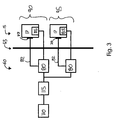
- die Bestromung der bestrombaren Fasern beim Wasser- fahrzeug gemäß
Fig. 1 in einem Blockschaltbild und - Fig. 4
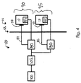
- eine alternative Bestromung der Fasern bei dem Wasser- fahrzeug gemäß
Fig. 1 in einem Blockschaltbild. - Bei dem erfindungsgemäßen Wasserfahrzeug handelt es um ein Unterseeboot 5. Das Unterseeboot 5 weist wie in an sich bekannter Weise einen Druckkörper 55 auf. Der Druckkörper 55 ist von einer Außenhaut 15 umgeben. Oberhalb des Druckkörpers 55 bildet ein Teil der Außenhaut 15 ein Oberdeck 10. In Bereichen des Oberdecks 10 des Unterseeboots 5 und weiteren, nachfolgend beschriebenen Bereichen ist die Außenhaut 15 mit einer Vielzahl von Kohlenstofffasern 17 verstärkt. Die Kohlenstofffasern 17 sind im horizontalen, begehbaren Bereich des Oberdecks 10 flächig verteilt. Ferner umgeben Kohlenstofffasern 17 Oberdeckklappen (in den Zeichnungen nicht gezeigt) des Oberdecks 10. Die Fasern sind dabei im Randbereich der Oberdeckklappen angeordnet. Die Kohlenstofffasern 17 sind in jedem der angesprochenen Bereiche jeweils als Teil eines Heizelementes ausgebildet und erwärmen bei Bestromung die Außenhaut 15 des Unterseeboots 5, um Bereiche zu trocknen, vor Vereisung zu schützen oder sie zu enteisen.
- Der Aufbau der Außenhaut 15 ist in
Fig. 2 im Schnitt entlang der Linie A-A im Bereich des Oberdecks 10 schematisch dargestellt. Dieser Schnitt ist dabei auch repräsentativ für den Aufbau sämtlicher anderen weiter unten beschriebenen Bereiche der Außenhaut 15, soweit nicht anders angegeben. - Die Außenhaut 15 umfasst einen Kern 20. Dieser Kern 20 der Außenhaut 15 weist eine Wabenstruktur bzw. eine Schaumstruktur auf, die das leichte und zugleich stabile Grundgerüst der Außenhaut 15 bildet. Außen umgeben ist der Kern 20 in an sich bekanntem Aufbau von einer Laminatschicht 25, welche im Wesentlichen aus kohlenstofffaserverstärktem Kunststoff besteht. Die Laminatschicht 25 kann zusätzlich oder stattdessen auch andere geeignete Materialien wie beispielsweise glasfaserverstärkten Kunststoff aufweisen. Innenliegend schließt sich an den Kern 20 eine weitere Laminatschicht 30 an, die identisch zur Laminatschicht 25 ausgebildet ist. Der Kern ist somit zwischen zwei Laminatschichten 25, 30 eingebettet.
- Außenliegend an der Laminatschicht 25 schließt sich eine CFK-Heizschicht 35 an. Die CFK-Heizschicht 35 besteht aus kohlenstofffaserverstärkten Kunststoff (CFK), der die Außenhaut 15 verstärkt. Die Kohlenstofffasern 17 des kohlenstofffaserverstärkten Kunststoffs sind in weiter unten näher beschriebener Weise bestrombar, sodass sie Teil eines Heizelementes sind. Die Fasern 17 liegen dabei als ein Gelege aus unidirektional orientierten Kohlenstofffasern 17 vor (alternativ können die Kohlenstofffasern 17 auch ein Vlies bilden). Bei Bestromung der Fasern 17 geht von den Fasern 17 und damit von der CFK-Heizschicht 35 eine Erwärmung der Außenhaut 15 aus. Die CFK-Heizschicht 35 ist nahe der Außenseite 18 der Außenhaut 15 angeordnet, sodass ein großer Anteil der von den Fasern 17 erzeugten Wärme zur Außenseite 18 der Außenhaut 15 geleitet wird.
- Weiter außenliegend befindet sich eine Schutzschicht 40, welche in erster Linie die innen liegenden Fasern 17, aber auch die Kunststoffmatrix der CFK-Heizschicht 35 und die weiteren innenliegenden Schichten der Außenhaut 15 vor (Salz-)Wasser, Säure, Luft und Sonnenlicht schützt. Dazu ist die Schutzschicht 40 als Gelcoat ausgebildet, welches einen hohen Harzanteil aufweist. Die Außenhaut 15 des Oberdecks 10 schließt an ihrer äußeren, dem umgebenden Seewasser ausgesetzten Seite 18 wie in an sich bekannter Weise mit einem Antirutschbelag 45 ab. Dieser Antirutschbelag ist dabei auf den begehbaren Bereich des Oberdecks 10 begrenzt, an anderen Bereichen der Außenhaut 15 ist kein Antirutschbelag vorgesehen. Innenliegend schließt die Außenhaut 15 mit einer weiteren Schutzschicht 50 ab. Auch diese Schutzschicht 50 weist einen hohen Harzanteil auf.
- Die Bestromung der Heizelemente ist schematisch in den
Figuren 3 und4 in zwei alternativen Ausführungsbeispielen erläutert. - In beiden Figuren ist schematisch ein Teil der Außenhaut 15 dargestellt, in welchem die bestrombaren Fasern 17 angeordnet sind. Dieser Teil liegt außerhalb des Druckkörpers 55, dessen Inneres mit 60 beziffert ist. Zur Bestromung der Fasern 17 der Außenhaut 15 sind Kontaktfolien 77 vorgesehen, mit denen die Enden der Fasern 17 kontaktiert sind. Die Kontaktfolien 77 sind hier beispielhaft durch Goldfolien realisiert, es kommen jedoch auch andere leitfähige Folien in Betracht. Die Kontaktfolien kontaktieren die Fasern 17 derart, dass sie gemeinsam einen Teil eines Heizstromkreises bilden, wie er nachfolgend beschrieben ist.
- Die Stärke der Bestromung der Fasern 17 wird von Heizreglern 80 bestimmt. Diese Heizregler 80 wirken hierzu als einstellbare Stromdrosseln an Zuleitungen 82 zur Bestromung der Heizelemente. Die Heizregler sind dabei zur Einstellung der Bestromung der Fasern 17 derart ausgebildet, dass geeignete Temperaturen im Bereich der Außenhaut 15 bzw. der Fasern 17 gewählt werden können. Diese Temperaturen können dann derart gewählt werden, dass eine effiziente und/oder zügige Erwärmung der Außenhaut 15 erfolgen kann.
- Um die Temperatur einzustellen, sind im Bereich der CFK-Heizschicht 35, also innerhalb der Außenhaut 15 und nahe den Fasern 17, Temperatursensoren 85 angeordnet, die die sich einstellende Temperatur in der Außenhaut 15 messen. Diese so ermittelten Temperaturwerte werden von den Temperatursensoren 85 zur Rückkopplung als Eingangswerte an die Heizregler 80 übermittelt. Bei Abweichungen von einer Solltemperatur können die Heizregler 80 die Bestromung der Heizelemente in Abhängigkeit von der erfassten Temperatur der Außenhaut 15 ändern und die Temperatur so auf die Solltemperatur regeln. In den dargestellten Ausführungsbespielen sind dabei jeweils Heizelemente in einem Bereich 90 und einem Bereich 95 angeordnet. Dabei verfügen beide Bereiche 90, 95 jeweils über einen Temperatursensor 85 und einen die Bestromung der jeweiligen Heizelemente regelnden Heizregler 80.
- Der Bereich 90 der Außenhaut 15 umfasst beispielhaft die zuvor erwähnten Oberdeckklappen (in den Zeichnungen nicht im Einzelnen dargestellt), wobei die dort angeordneten Fasern 17 im Bedarfsfalle eine Vereisung der Oberdeckklappen verhindern. Im Bereich 95 der Außenhaut 15 befinden sich Oberdeckflächen, welche mit den Fasern 17 von einer Vereisung freigehalten werden oder im Falle der Vereisung enteist werden können.
- Der Bereich 95 ist in einem weiteren, hier nicht gesondert dargestellten, Ausführungsbeispiel der Bereich eines Turms des Unterseebootes 5, welcher durch Bestromung der Fasern 17 vor einer Vereisung geschützt bzw. enteist wird. In einem weiteren nicht gesondert dargestellten Ausführungsbeispiel handelt es sich bei dem Bereich 95 um einen Bereich der Außenhaut 15, an welchem ein Ausfahrgerät des Unterseebootes 5 austritt. Alternativ ist der Bereich 95 ein Bereich 95 der Außenhaut 15 mit einer Antenne, an welchem die Fasern 17 zur Trocknung des Bereichs 95 von Wasser vorgesehen sind, beispielsweise in Form einer Antennenhaube. Es versteht sich, dass die Bereiche 90, 95 gemäß vorgenannten Ausführungsbeispielen jeweils unabhängig voneinander ausführbare Ausgestaltungen der Erfindung darstellen. Die vorgenannten Bereiche, in denen eine Beheizung der Außenhaut vorgesehen ist, sind nur beispielhaft zu verstehen. Solche Heizelemente können überall dort vorgesehen sein, wo es zweckmäßig erscheint.
- In dem in
Fig. 3 dargestellten Ausführungsbeispiel wird die elektrische Energie zur Bestromung der Fasern 17 über die Zuleitungen 82 vom Bordstromnetz 100 des Unterseeboots 5 geliefert. Das Bordstromnetz 100 ist ein Wechselstromnetz. Um die Fasern 17 mit Gleichstrom zu bestromen, sind die Zuleitungen 82 über einen AC/DC-Konverter 105 an das Bordstromnetz 100 angeschlossen, so dass die Fasern 17 jeweils Teile eines Heizstromkreises bilden. Die Heizregler 80 sind dabei als Drosseln an den Zuleitungen 82 zwischen AC/DC-Konverter 105 und Kontaktfolien 77 zwischengeschaltet wie oben beschrieben. - In einem alternativen Ausführungsbeispiel (
Fig. 4 ) sind die Fasern 17 über die Zuleitungen 82 von einer Batterie 110 des Unterseebootes 5 bestromt, welche bereits den zur Bestromung der Fasern 17 besonders geeigneten Gleichstrom liefert. Auch hier sind die Fasern 17 folglich jeweils Teil eines Heizstromkreises. Um das Spannungsniveau der Batterie 110 an das von Heizregler 80 und Heizelementen geforderte Spannungsniveau anzupassen, ist zwischen der Batterie 110 und den Zuleitungen 82 ein DC/DC-Konverter 115 angeschlossen. Die Heizregler 80 sind dabei zur Einstellung des Heizstroms zwischen DC/DC-Konverter 115 und den Fasern 17 zwischengeschaltet. -
- 5 -
- Unterseeboot
- 10 -
- Oberdeck
- 15 -
- Außenhaut
- 17 -
- Kohlenstofffasern
- 18 -
- Außenseite
- 20 -
- Kern
- 25 -
- Laminatschicht
- 30 -
- Laminatschicht
- 35 -
- CFK-Heizschicht
- 40 -
- Schutzschicht
- 45 -
- Antirutschbelag
- 50 -
- Schutzschicht
- 55 -
- Druckkörper
- 60 -
- Innenbordbereich
- 77 -
- Kontaktfolien
- 80 -
- Heizregler
- 82
- Zuleitungen
- 85 -
- Temperatursensor
- 90 -
- Bereich
- 95 -
- Bereich
- 100 -
- Bordstromnetz
- 105 -
- AC/DC-Konverter
- 110 -
- Batterie
- 115 -
- DC/DC-Konverter
Claims (16)
- Wasserfahrzeug, bei welchem mindestens ein Teil der Außenhaut (15) aus einem mit Fasern (17) verstärkten Verbundwerkstoff gebildet ist und bei welchem zumindest eine Faser (17) als elektrisches Heizelement ausgebildet ist oder einen Teil eines solchen bildet.
- Wasserfahrzeug nach Anspruch 1, bei welchem der Verbundwerkstoff mit Kohlenstofffasern (17) verstärkter Kunststoff ist.
- Wasserfahrzeug nach Anspruch 1 oder 2, bei welchem das Heizelement ein oder mehrere Faserbündel aufweist.
- Wasserfahrzeug nach einem der vorhergehenden Ansprüche, bei welchem die bestrombare Faser (17) der Außenseite (18) der Außenhaut (15) näher als der Innenseite angeordnet ist.
- Wasserfahrzeug nach einem der vorhergehenden Ansprüche, bei welchem die Faser (17) zur Bestromung mit Gleichstrom ausgebildet ist.
- Wasserfahrzeug nach einem der vorhergehenden Ansprüche, bei welchem zwischen der Außenseite (18) der Außenhaut (15) und der Faser (17) eine Schutzschicht (40) vorhanden ist.
- Wasserfahrzeug nach einem der vorhergehenden Ansprüche, bei welchem die bestrombare Faser (17) im Deckbereich (10) der Außenhaut (15) angeordnet ist.
- Wasserfahrzeug nach einem der vorhergehenden Ansprüche, bei welchem die Außenhaut (15) einen Klappenbereich (90) umfasst und bei welchem die bestrombare Faser (17) in dem Klappenbereich (90) angeordnet ist.
- Wasserfahrzeug nach einem der vorhergehenden Ansprüche, welches eine Antenne umfasst und bei welchem ein Teil der Außenhaut mit der bestrombaren Faser eine Antennenhaube bildet.
- Wasserfahrzeug nach einem der vorhergehenden Ansprüche, bei welchem mehrere bestrombare Fasern (17) unidirektional orientiert sind und gemeinsam als Heizelement ausgebildet sind oder einen Teil eines Heizelementes bilden.
- Wasserfahrzeug nach einem der vorhergehenden Ansprüche, bei welchem mehrere Fasern (17) ein Vlies bilden, das als Heizelement ausgebildet ist oder einen Teil eines solchen bildet.
- Wasserfahrzeug nach einem der vorhergehenden Ansprüche, welches ein Unterseeboot (5) ist.
- Wasserfahrzeug nach einem der vorhergehenden Ansprüche, welches einen Turm aufweist und bei welchem die bestrombare Faser (17) im Bereich (95) des Turms angeordnet ist.
- Wasserfahrzeug nach einem der vorhergehenden Ansprüche mit zumindest einem Ausfahrgerät, bei welchem die bestrombare Faser in oder an einem Bereich (95) der Außenhaut angeordnet ist, welcher den Austrittsbereich des Ausfahrgerätes bildet.
- Wasserfahrzeug nach einem der vorhergehenden Ansprüche, bei welchem Steuermittel zur Steuerung der Stromstärke des Heizelementes vorhanden sind.
- Wasserfahrzeug nach Anspruch 15, bei welchem die Steuermittel einen Teil eines Heizreglers (80) bilden, bei welchem die Stromstärke des Heizelementes die Stellgröße bildet und bei welchem die Temperatur der Faser (17) und/oder eines Bereichs (90; 95) der Außenhaut (15) die Regelgröße bildet, und bei welchem ein Temperatursensor (85) in oder an der Außenhaut (15) zur Erfassung der Regelgröße vorgesehen ist.
Applications Claiming Priority (1)
| Application Number | Priority Date | Filing Date | Title |
|---|---|---|---|
| DE102009030125A DE102009030125A1 (de) | 2009-06-24 | 2009-06-24 | Wasserfahrzeug |
Publications (2)
| Publication Number | Publication Date |
|---|---|
| EP2266872A1 EP2266872A1 (de) | 2010-12-29 |
| EP2266872B1 true EP2266872B1 (de) | 2011-10-12 |
Family
ID=42829514
Family Applications (1)
| Application Number | Title | Priority Date | Filing Date |
|---|---|---|---|
| EP10005199A Active EP2266872B1 (de) | 2009-06-24 | 2010-05-18 | Wasserfahrzeug |
Country Status (5)
| Country | Link |
|---|---|
| EP (1) | EP2266872B1 (de) |
| KR (1) | KR101304260B1 (de) |
| AT (1) | ATE528205T1 (de) |
| DE (1) | DE102009030125A1 (de) |
| ES (1) | ES2372916T3 (de) |
Cited By (1)
| Publication number | Priority date | Publication date | Assignee | Title |
|---|---|---|---|---|
| WO2021169680A1 (zh) * | 2020-02-28 | 2021-09-02 | 江苏科技大学 | 一种大深度潜航器、大深度潜航器用耐压壳体及其组装方法 |
Families Citing this family (1)
| Publication number | Priority date | Publication date | Assignee | Title |
|---|---|---|---|---|
| CN113335461A (zh) * | 2021-06-08 | 2021-09-03 | 北京格睿能源科技有限公司 | 破冰船及其加热方法 |
Family Cites Families (10)
| Publication number | Priority date | Publication date | Assignee | Title |
|---|---|---|---|---|
| DE1182550B (de) * | 1962-10-10 | 1964-11-26 | Friedrich Wilhelm Pleuger | Einrichtung zum Schutz eines Bugstrahlruders vor Vereisung |
| US4102144A (en) * | 1977-05-31 | 1978-07-25 | Global Marine, Inc. | Method and apparatus for protecting offshore structures against forces from moving ice sheets |
| US4152999A (en) * | 1977-12-05 | 1979-05-08 | Mitsui Engineering And Shipbuilding Co., Ltd. | Ice-breaking apparatus for ships and barges for operation on icy waters |
| FR2623220B1 (fr) * | 1987-11-17 | 1991-07-26 | Doris Engineering | Procede et dispositif destines a briser localement une couche de glace en mer froide |
| US5593332A (en) * | 1988-09-20 | 1997-01-14 | Sundstrand Corporation | Ice penetrating communication buoy |
| US4942078A (en) * | 1988-09-30 | 1990-07-17 | Rockwell International Corporation | Electrically heated structural composite and method of its manufacture |
| ATE104493T1 (de) * | 1990-01-24 | 1994-04-15 | Hastings Otis | Elektrisch leitendes laminat fuer temperaturregelung von oberflaechen. |
| AT2468U1 (de) * | 1997-06-23 | 1998-11-25 | Macher David | Sitz, insbesondere fahrzeugsitz |
| DE102005052109B3 (de) * | 2005-11-02 | 2007-05-24 | Howaldtswerke-Deutsche Werft Gmbh | Unterseeboot |
| DE202008015485U1 (de) * | 2008-11-21 | 2009-03-26 | Gendelman, Jaakov | Heizelement |
-
2009
- 2009-06-24 DE DE102009030125A patent/DE102009030125A1/de not_active Withdrawn
-
2010
- 2010-05-18 EP EP10005199A patent/EP2266872B1/de active Active
- 2010-05-18 ES ES10005199T patent/ES2372916T3/es active Active
- 2010-05-18 AT AT10005199T patent/ATE528205T1/de active
- 2010-06-17 KR KR1020100057435A patent/KR101304260B1/ko active Active
Cited By (1)
| Publication number | Priority date | Publication date | Assignee | Title |
|---|---|---|---|---|
| WO2021169680A1 (zh) * | 2020-02-28 | 2021-09-02 | 江苏科技大学 | 一种大深度潜航器、大深度潜航器用耐压壳体及其组装方法 |
Also Published As
| Publication number | Publication date |
|---|---|
| DE102009030125A1 (de) | 2011-02-10 |
| KR101304260B1 (ko) | 2013-09-05 |
| ES2372916T3 (es) | 2012-01-27 |
| EP2266872A1 (de) | 2010-12-29 |
| KR20120065460A (ko) | 2012-06-21 |
| ATE528205T1 (de) | 2011-10-15 |
Similar Documents
| Publication | Publication Date | Title |
|---|---|---|
| DE10016261C2 (de) | Kompakte mikrowellentechnische Einrichtung zum Enteisen oder Vorbeugen einer Vereisung | |
| DE69307353T2 (de) | Modulablassmast eines Flugzeuges | |
| DE60018936T2 (de) | Redundantes system zur enteisung und zum vereisungsschutz für luftfahrzeuge | |
| DE102006031330B4 (de) | Für Eis empfänglicher Abschnitt eines Flugzeugs, insbesondere Flugtriebwerk- Zelleneinlasslippe, umfassend ein Eisschutzsystem, Flugtriebwerk mit einer solchen Einlasslippe sowie ein Verfahren zum Schutz einer solchen Einlasslippe vor Vereisung | |
| DE10016259A1 (de) | Kompaktes millimeterwellentechnisches System zum Enteisen und/oder Vorbeugen einer Vereisung der äußeren Oberfläche von meteorologischen Einflüssen ausgesetzten Hohlraum- oder Schalenstrukturen | |
| EP2616321B1 (de) | Magnus-rotor | |
| WO2012159608A2 (de) | Verbundstruktur mit eisschutzvorrichtung sowie herstellverfahren | |
| DE102007061991A1 (de) | Brennstoffzellensystemmodul | |
| EP2829442B1 (de) | Anordnung zum Enttauen und/oder Enteisen eines Radarsensors in einem Kraftfahrzeug, Verfahren zum Betreiben einer einen Radarsensor aufweisenden Radareinrichtung und Baugruppe mit einer Anordnung | |
| EP2616329B1 (de) | Schiff mit öffnung zum entfernen eines energieversorgungssystems | |
| DE202018102696U1 (de) | Windkraftanlage und ihre Blattenteisungsvorrichtung | |
| EP2266872A1 (de) | Wasserfahrzeug | |
| EP2462023B1 (de) | Vorrichtung zur enteisung von fahrzeugen, insbesondere flugzeugen | |
| DE3015998C2 (de) | Anordnung zur Beheizung großflächiger Laminatformkörper | |
| DE102015115450A1 (de) | Rohrheizung | |
| DE102009003937A1 (de) | Flugzeugklimaanlage mit einer verringerten Vereisungsgefahr | |
| EP1438727A1 (de) | Heizfolie aus mehreren schichten und verfahren zu deren herstellung | |
| DE102010045450A1 (de) | Anordnung zur Enteisung eines Oberflächenbereichs eines Luftfahrzeugs | |
| EP3317134B1 (de) | Auftauvorrichtung für betriebsflüssigkeitsbehälter | |
| EP3447284A1 (de) | Rotorblatt für eine windenergieanlage, verfahren zum kontaktieren einer elektrisch leitfähigen beschichtung auf ein rotorblatt einer windenergieanlage und windener-gieanlage | |
| CH710512A2 (de) | Flächenheizung. | |
| DE102014215658A1 (de) | Enteisung eines Fahrzeugs | |
| DE202007013399U1 (de) | Vorrichtung zum Verscheuchen und Vergrämen von flugfähigen Vögeln, insbesondere von Möwen | |
| EP4112446B1 (de) | Abflussmast | |
| DE102022115054B4 (de) | Flügelkörper |
Legal Events
| Date | Code | Title | Description |
|---|---|---|---|
| PUAI | Public reference made under article 153(3) epc to a published international application that has entered the european phase |
Free format text: ORIGINAL CODE: 0009012 |
|
| 17P | Request for examination filed |
Effective date: 20101104 |
|
| AK | Designated contracting states |
Kind code of ref document: A1 Designated state(s): AL AT BE BG CH CY CZ DE DK EE ES FI FR GB GR HR HU IE IS IT LI LT LU LV MC MK MT NL NO PL PT RO SE SI SK SM TR |
|
| AX | Request for extension of the european patent |
Extension state: BA ME RS |
|
| GRAP | Despatch of communication of intention to grant a patent |
Free format text: ORIGINAL CODE: EPIDOSNIGR1 |
|
| RIC1 | Information provided on ipc code assigned before grant |
Ipc: B63G 8/04 20060101ALI20110315BHEP Ipc: B63B 35/08 20060101AFI20110315BHEP Ipc: B63G 8/00 20060101ALI20110315BHEP |
|
| GRAS | Grant fee paid |
Free format text: ORIGINAL CODE: EPIDOSNIGR3 |
|
| GRAA | (expected) grant |
Free format text: ORIGINAL CODE: 0009210 |
|
| AK | Designated contracting states |
Kind code of ref document: B1 Designated state(s): AL AT BE BG CH CY CZ DE DK EE ES FI FR GB GR HR HU IE IS IT LI LT LU LV MC MK MT NL NO PL PT RO SE SI SK SM TR |
|
| REG | Reference to a national code |
Ref country code: GB Ref legal event code: FG4D Free format text: NOT ENGLISH |
|
| REG | Reference to a national code |
Ref country code: CH Ref legal event code: EP |
|
| REG | Reference to a national code |
Ref country code: IE Ref legal event code: FG4D |
|
| REG | Reference to a national code |
Ref country code: DE Ref legal event code: R096 Ref document number: 502010000149 Country of ref document: DE Effective date: 20120119 |
|
| REG | Reference to a national code |
Ref country code: NL Ref legal event code: T3 |
|
| REG | Reference to a national code |
Ref country code: ES Ref legal event code: FG2A Ref document number: 2372916 Country of ref document: ES Kind code of ref document: T3 Effective date: 20120127 |
|
| REG | Reference to a national code |
Ref country code: SE Ref legal event code: TRGR |
|
| LTIE | Lt: invalidation of european patent or patent extension |
Effective date: 20111012 |
|
| REG | Reference to a national code |
Ref country code: GR Ref legal event code: EP Ref document number: 20110403043 Country of ref document: GR Effective date: 20120206 |
|
| PG25 | Lapsed in a contracting state [announced via postgrant information from national office to epo] |
Ref country code: IS Free format text: LAPSE BECAUSE OF FAILURE TO SUBMIT A TRANSLATION OF THE DESCRIPTION OR TO PAY THE FEE WITHIN THE PRESCRIBED TIME-LIMIT Effective date: 20120212 Ref country code: LT Free format text: LAPSE BECAUSE OF FAILURE TO SUBMIT A TRANSLATION OF THE DESCRIPTION OR TO PAY THE FEE WITHIN THE PRESCRIBED TIME-LIMIT Effective date: 20111012 Ref country code: NO Free format text: LAPSE BECAUSE OF FAILURE TO SUBMIT A TRANSLATION OF THE DESCRIPTION OR TO PAY THE FEE WITHIN THE PRESCRIBED TIME-LIMIT Effective date: 20120112 |
|
| REG | Reference to a national code |
Ref country code: IE Ref legal event code: FD4D |
|
| PG25 | Lapsed in a contracting state [announced via postgrant information from national office to epo] |
Ref country code: HR Free format text: LAPSE BECAUSE OF FAILURE TO SUBMIT A TRANSLATION OF THE DESCRIPTION OR TO PAY THE FEE WITHIN THE PRESCRIBED TIME-LIMIT Effective date: 20111012 Ref country code: LV Free format text: LAPSE BECAUSE OF FAILURE TO SUBMIT A TRANSLATION OF THE DESCRIPTION OR TO PAY THE FEE WITHIN THE PRESCRIBED TIME-LIMIT Effective date: 20111012 Ref country code: SI Free format text: LAPSE BECAUSE OF FAILURE TO SUBMIT A TRANSLATION OF THE DESCRIPTION OR TO PAY THE FEE WITHIN THE PRESCRIBED TIME-LIMIT Effective date: 20111012 Ref country code: PT Free format text: LAPSE BECAUSE OF FAILURE TO SUBMIT A TRANSLATION OF THE DESCRIPTION OR TO PAY THE FEE WITHIN THE PRESCRIBED TIME-LIMIT Effective date: 20120213 |
|
| PGFP | Annual fee paid to national office [announced via postgrant information from national office to epo] |
Ref country code: TR Payment date: 20120320 Year of fee payment: 3 |
|
| PG25 | Lapsed in a contracting state [announced via postgrant information from national office to epo] |
Ref country code: CY Free format text: LAPSE BECAUSE OF FAILURE TO SUBMIT A TRANSLATION OF THE DESCRIPTION OR TO PAY THE FEE WITHIN THE PRESCRIBED TIME-LIMIT Effective date: 20111012 |
|
| PG25 | Lapsed in a contracting state [announced via postgrant information from national office to epo] |
Ref country code: SK Free format text: LAPSE BECAUSE OF FAILURE TO SUBMIT A TRANSLATION OF THE DESCRIPTION OR TO PAY THE FEE WITHIN THE PRESCRIBED TIME-LIMIT Effective date: 20111012 Ref country code: EE Free format text: LAPSE BECAUSE OF FAILURE TO SUBMIT A TRANSLATION OF THE DESCRIPTION OR TO PAY THE FEE WITHIN THE PRESCRIBED TIME-LIMIT Effective date: 20111012 Ref country code: CZ Free format text: LAPSE BECAUSE OF FAILURE TO SUBMIT A TRANSLATION OF THE DESCRIPTION OR TO PAY THE FEE WITHIN THE PRESCRIBED TIME-LIMIT Effective date: 20111012 Ref country code: BG Free format text: LAPSE BECAUSE OF FAILURE TO SUBMIT A TRANSLATION OF THE DESCRIPTION OR TO PAY THE FEE WITHIN THE PRESCRIBED TIME-LIMIT Effective date: 20120112 Ref country code: DK Free format text: LAPSE BECAUSE OF FAILURE TO SUBMIT A TRANSLATION OF THE DESCRIPTION OR TO PAY THE FEE WITHIN THE PRESCRIBED TIME-LIMIT Effective date: 20111012 Ref country code: IE Free format text: LAPSE BECAUSE OF FAILURE TO SUBMIT A TRANSLATION OF THE DESCRIPTION OR TO PAY THE FEE WITHIN THE PRESCRIBED TIME-LIMIT Effective date: 20111012 |
|
| PLBE | No opposition filed within time limit |
Free format text: ORIGINAL CODE: 0009261 |
|
| STAA | Information on the status of an ep patent application or granted ep patent |
Free format text: STATUS: NO OPPOSITION FILED WITHIN TIME LIMIT |
|
| PG25 | Lapsed in a contracting state [announced via postgrant information from national office to epo] |
Ref country code: PL Free format text: LAPSE BECAUSE OF FAILURE TO SUBMIT A TRANSLATION OF THE DESCRIPTION OR TO PAY THE FEE WITHIN THE PRESCRIBED TIME-LIMIT Effective date: 20111012 Ref country code: RO Free format text: LAPSE BECAUSE OF FAILURE TO SUBMIT A TRANSLATION OF THE DESCRIPTION OR TO PAY THE FEE WITHIN THE PRESCRIBED TIME-LIMIT Effective date: 20111012 |
|
| 26N | No opposition filed |
Effective date: 20120713 |
|
| REG | Reference to a national code |
Ref country code: DE Ref legal event code: R097 Ref document number: 502010000149 Country of ref document: DE Effective date: 20120713 |
|
| BERE | Be: lapsed |
Owner name: HOWALDTSWERKE-DEUTSCHE WERFT G.M.B.H. Effective date: 20120531 |
|
| PG25 | Lapsed in a contracting state [announced via postgrant information from national office to epo] |
Ref country code: MC Free format text: LAPSE BECAUSE OF NON-PAYMENT OF DUE FEES Effective date: 20120531 |
|
| REG | Reference to a national code |
Ref country code: DE Ref legal event code: R082 Ref document number: 502010000149 Country of ref document: DE Representative=s name: PATENTANWAELTE VOLLMANN & HEMMER, DE |
|
| PG25 | Lapsed in a contracting state [announced via postgrant information from national office to epo] |
Ref country code: BE Free format text: LAPSE BECAUSE OF NON-PAYMENT OF DUE FEES Effective date: 20120531 Ref country code: MK Free format text: LAPSE BECAUSE OF FAILURE TO SUBMIT A TRANSLATION OF THE DESCRIPTION OR TO PAY THE FEE WITHIN THE PRESCRIBED TIME-LIMIT Effective date: 20111012 |
|
| REG | Reference to a national code |
Ref country code: NL Ref legal event code: SD Effective date: 20130312 |
|
| REG | Reference to a national code |
Ref country code: DE Ref legal event code: R082 Ref document number: 502010000149 Country of ref document: DE Representative=s name: PATENTANWAELTE VOLLMANN & HEMMER, DE Effective date: 20130206 Ref country code: DE Ref legal event code: R081 Ref document number: 502010000149 Country of ref document: DE Owner name: THYSSENKRUPP MARINE SYSTEMS GMBH, DE Free format text: FORMER OWNER: HOWALDTSWERKE-DEUTSCHE WERFT GMBH, 24143 KIEL, DE Effective date: 20130206 |
|
| REG | Reference to a national code |
Ref country code: FR Ref legal event code: CD Owner name: THYSSENKRUPP MARINE SYSTEMS GMBH Effective date: 20130313 |
|
| REG | Reference to a national code |
Ref country code: NL Ref legal event code: TD Effective date: 20130417 |
|
| PGFP | Annual fee paid to national office [announced via postgrant information from national office to epo] |
Ref country code: ES Payment date: 20130320 Year of fee payment: 4 |
|
| PGFP | Annual fee paid to national office [announced via postgrant information from national office to epo] |
Ref country code: GR Payment date: 20130328 Year of fee payment: 4 |
|
| PG25 | Lapsed in a contracting state [announced via postgrant information from national office to epo] |
Ref country code: FI Free format text: LAPSE BECAUSE OF FAILURE TO SUBMIT A TRANSLATION OF THE DESCRIPTION OR TO PAY THE FEE WITHIN THE PRESCRIBED TIME-LIMIT Effective date: 20111012 |
|
| PG25 | Lapsed in a contracting state [announced via postgrant information from national office to epo] |
Ref country code: MT Free format text: LAPSE BECAUSE OF FAILURE TO SUBMIT A TRANSLATION OF THE DESCRIPTION OR TO PAY THE FEE WITHIN THE PRESCRIBED TIME-LIMIT Effective date: 20111012 |
|
| PGFP | Annual fee paid to national office [announced via postgrant information from national office to epo] |
Ref country code: IT Payment date: 20130531 Year of fee payment: 4 Ref country code: NL Payment date: 20130513 Year of fee payment: 4 |
|
| REG | Reference to a national code |
Ref country code: ES Ref legal event code: PC2A Owner name: THYSSENKRUPP MARINE SYSTEMS GMBH Effective date: 20130912 |
|
| PG25 | Lapsed in a contracting state [announced via postgrant information from national office to epo] |
Ref country code: AL Free format text: LAPSE BECAUSE OF FAILURE TO SUBMIT A TRANSLATION OF THE DESCRIPTION OR TO PAY THE FEE WITHIN THE PRESCRIBED TIME-LIMIT Effective date: 20111012 |
|
| PG25 | Lapsed in a contracting state [announced via postgrant information from national office to epo] |
Ref country code: LU Free format text: LAPSE BECAUSE OF NON-PAYMENT OF DUE FEES Effective date: 20120518 Ref country code: SM Free format text: LAPSE BECAUSE OF FAILURE TO SUBMIT A TRANSLATION OF THE DESCRIPTION OR TO PAY THE FEE WITHIN THE PRESCRIBED TIME-LIMIT Effective date: 20111012 |
|
| PG25 | Lapsed in a contracting state [announced via postgrant information from national office to epo] |
Ref country code: HU Free format text: LAPSE BECAUSE OF FAILURE TO SUBMIT A TRANSLATION OF THE DESCRIPTION OR TO PAY THE FEE WITHIN THE PRESCRIBED TIME-LIMIT Effective date: 20100518 |
|
| REG | Reference to a national code |
Ref country code: NL Ref legal event code: V1 Effective date: 20141201 |
|
| REG | Reference to a national code |
Ref country code: CH Ref legal event code: PL |
|
| PG25 | Lapsed in a contracting state [announced via postgrant information from national office to epo] |
Ref country code: LI Free format text: LAPSE BECAUSE OF NON-PAYMENT OF DUE FEES Effective date: 20140531 Ref country code: CH Free format text: LAPSE BECAUSE OF NON-PAYMENT OF DUE FEES Effective date: 20140531 Ref country code: GR Free format text: LAPSE BECAUSE OF NON-PAYMENT OF DUE FEES Effective date: 20141203 |
|
| REG | Reference to a national code |
Ref country code: GR Ref legal event code: ML Ref document number: 20110403043 Country of ref document: GR Effective date: 20141203 |
|
| REG | Reference to a national code |
Ref country code: DE Ref legal event code: R084 Ref document number: 502010000149 Country of ref document: DE |
|
| PG25 | Lapsed in a contracting state [announced via postgrant information from national office to epo] |
Ref country code: NL Free format text: LAPSE BECAUSE OF NON-PAYMENT OF DUE FEES Effective date: 20141201 |
|
| PG25 | Lapsed in a contracting state [announced via postgrant information from national office to epo] |
Ref country code: IT Free format text: LAPSE BECAUSE OF NON-PAYMENT OF DUE FEES Effective date: 20140518 |
|
| REG | Reference to a national code |
Ref country code: DE Ref legal event code: R084 Ref document number: 502010000149 Country of ref document: DE Effective date: 20150206 |
|
| REG | Reference to a national code |
Ref country code: ES Ref legal event code: FD2A Effective date: 20150626 |
|
| PG25 | Lapsed in a contracting state [announced via postgrant information from national office to epo] |
Ref country code: ES Free format text: LAPSE BECAUSE OF NON-PAYMENT OF DUE FEES Effective date: 20140519 |
|
| REG | Reference to a national code |
Ref country code: DE Ref legal event code: R082 Ref document number: 502010000149 Country of ref document: DE |
|
| REG | Reference to a national code |
Ref country code: FR Ref legal event code: PLFP Year of fee payment: 7 |
|
| REG | Reference to a national code |
Ref country code: AT Ref legal event code: MM01 Ref document number: 528205 Country of ref document: AT Kind code of ref document: T Effective date: 20150518 |
|
| PG25 | Lapsed in a contracting state [announced via postgrant information from national office to epo] |
Ref country code: AT Free format text: LAPSE BECAUSE OF NON-PAYMENT OF DUE FEES Effective date: 20150518 |
|
| REG | Reference to a national code |
Ref country code: FR Ref legal event code: PLFP Year of fee payment: 8 |
|
| PG25 | Lapsed in a contracting state [announced via postgrant information from national office to epo] |
Ref country code: TR Free format text: LAPSE BECAUSE OF NON-PAYMENT OF DUE FEES Effective date: 20140518 |
|
| REG | Reference to a national code |
Ref country code: FR Ref legal event code: PLFP Year of fee payment: 9 |
|
| REG | Reference to a national code |
Ref country code: DE Ref legal event code: R081 Ref document number: 502010000149 Country of ref document: DE Owner name: THYSSENKRUPP MARINE SYSTEMS GMBH, DE Free format text: FORMER OWNER: THYSSENKRUPP MARINE SYSTEMS GMBH, 24143 KIEL, DE |
|
| PGFP | Annual fee paid to national office [announced via postgrant information from national office to epo] |
Ref country code: DE Payment date: 20250521 Year of fee payment: 16 |
|
| PGFP | Annual fee paid to national office [announced via postgrant information from national office to epo] |
Ref country code: GB Payment date: 20250521 Year of fee payment: 16 |
|
| PGFP | Annual fee paid to national office [announced via postgrant information from national office to epo] |
Ref country code: FR Payment date: 20250528 Year of fee payment: 16 |
|
| PGFP | Annual fee paid to national office [announced via postgrant information from national office to epo] |
Ref country code: SE Payment date: 20250521 Year of fee payment: 16 |
|
| REG | Reference to a national code |
Ref country code: DE Ref legal event code: R081 Ref document number: 502010000149 Country of ref document: DE Owner name: TKMS GMBH, DE Free format text: FORMER OWNER: THYSSENKRUPP MARINE SYSTEMS GMBH, 24143 KIEL, DE |