EP2265166B1 - Vorübergehende elektrodenverbindung für drahtlose schrittmachersysteme - Google Patents
Vorübergehende elektrodenverbindung für drahtlose schrittmachersysteme Download PDFInfo
- Publication number
- EP2265166B1 EP2265166B1 EP09725046.8A EP09725046A EP2265166B1 EP 2265166 B1 EP2265166 B1 EP 2265166B1 EP 09725046 A EP09725046 A EP 09725046A EP 2265166 B1 EP2265166 B1 EP 2265166B1
- Authority
- EP
- European Patent Office
- Prior art keywords
- delivery system
- stimulator
- receiver
- electrode
- electrical
- Prior art date
- Legal status (The legal status is an assumption and is not a legal conclusion. Google has not performed a legal analysis and makes no representation as to the accuracy of the status listed.)
- Active
Links
Images


Classifications
-
- A—HUMAN NECESSITIES
- A61—MEDICAL OR VETERINARY SCIENCE; HYGIENE
- A61N—ELECTROTHERAPY; MAGNETOTHERAPY; RADIATION THERAPY; ULTRASOUND THERAPY
- A61N1/00—Electrotherapy; Circuits therefor
- A61N1/18—Applying electric currents by contact electrodes
- A61N1/32—Applying electric currents by contact electrodes alternating or intermittent currents
- A61N1/36—Applying electric currents by contact electrodes alternating or intermittent currents for stimulation
- A61N1/372—Arrangements in connection with the implantation of stimulators
- A61N1/378—Electrical supply
- A61N1/3787—Electrical supply from an external energy source
-
- A—HUMAN NECESSITIES
- A61—MEDICAL OR VETERINARY SCIENCE; HYGIENE
- A61B—DIAGNOSIS; SURGERY; IDENTIFICATION
- A61B5/00—Measuring for diagnostic purposes; Identification of persons
- A61B5/24—Detecting, measuring or recording bioelectric or biomagnetic signals of the body or parts thereof
- A61B5/25—Bioelectric electrodes therefor
- A61B5/279—Bioelectric electrodes therefor specially adapted for particular uses
- A61B5/28—Bioelectric electrodes therefor specially adapted for particular uses for electrocardiography [ECG]
- A61B5/283—Invasive
- A61B5/29—Invasive for permanent or long-term implantation
-
- A—HUMAN NECESSITIES
- A61—MEDICAL OR VETERINARY SCIENCE; HYGIENE
- A61N—ELECTROTHERAPY; MAGNETOTHERAPY; RADIATION THERAPY; ULTRASOUND THERAPY
- A61N1/00—Electrotherapy; Circuits therefor
- A61N1/18—Applying electric currents by contact electrodes
- A61N1/32—Applying electric currents by contact electrodes alternating or intermittent currents
- A61N1/36—Applying electric currents by contact electrodes alternating or intermittent currents for stimulation
- A61N1/362—Heart stimulators
- A61N1/37—Monitoring; Protecting
- A61N1/3702—Physiological parameters
-
- A—HUMAN NECESSITIES
- A61—MEDICAL OR VETERINARY SCIENCE; HYGIENE
- A61N—ELECTROTHERAPY; MAGNETOTHERAPY; RADIATION THERAPY; ULTRASOUND THERAPY
- A61N1/00—Electrotherapy; Circuits therefor
- A61N1/18—Applying electric currents by contact electrodes
- A61N1/32—Applying electric currents by contact electrodes alternating or intermittent currents
- A61N1/36—Applying electric currents by contact electrodes alternating or intermittent currents for stimulation
- A61N1/372—Arrangements in connection with the implantation of stimulators
- A61N1/37205—Microstimulators, e.g. implantable through a cannula
-
- A—HUMAN NECESSITIES
- A61—MEDICAL OR VETERINARY SCIENCE; HYGIENE
- A61N—ELECTROTHERAPY; MAGNETOTHERAPY; RADIATION THERAPY; ULTRASOUND THERAPY
- A61N1/00—Electrotherapy; Circuits therefor
- A61N1/18—Applying electric currents by contact electrodes
- A61N1/32—Applying electric currents by contact electrodes alternating or intermittent currents
- A61N1/36—Applying electric currents by contact electrodes alternating or intermittent currents for stimulation
- A61N1/372—Arrangements in connection with the implantation of stimulators
- A61N1/375—Constructional arrangements, e.g. casings
- A61N1/3756—Casings with electrodes thereon, e.g. leadless stimulators
-
- A—HUMAN NECESSITIES
- A61—MEDICAL OR VETERINARY SCIENCE; HYGIENE
- A61B—DIAGNOSIS; SURGERY; IDENTIFICATION
- A61B17/00—Surgical instruments, devices or methods
- A61B17/34—Trocars; Puncturing needles
- A61B17/3468—Trocars; Puncturing needles for implanting or removing devices, e.g. prostheses, implants, seeds, wires
-
- A—HUMAN NECESSITIES
- A61—MEDICAL OR VETERINARY SCIENCE; HYGIENE
- A61N—ELECTROTHERAPY; MAGNETOTHERAPY; RADIATION THERAPY; ULTRASOUND THERAPY
- A61N1/00—Electrotherapy; Circuits therefor
- A61N1/18—Applying electric currents by contact electrodes
- A61N1/32—Applying electric currents by contact electrodes alternating or intermittent currents
- A61N1/36—Applying electric currents by contact electrodes alternating or intermittent currents for stimulation
- A61N1/372—Arrangements in connection with the implantation of stimulators
- A61N1/37211—Means for communicating with stimulators
- A61N1/37217—Means for communicating with stimulators characterised by the communication link, e.g. acoustic or tactile
- A61N1/37223—Circuits for electromagnetic coupling
Definitions
- the field of the present invention relates generally to implanted devices for tissue stimulation, monitoring, and other therapeutic or diagnostic functions, and specifically to implantable devices for the stimulation of cardiac tissue, for example pacemakers or implantable cardioverter-defibrillators (ICDs). More specifically, it pertains to such devices utilizing wireless energy transfer, for example using ultrasound energy.
- implantable devices for the stimulation of cardiac tissue for example pacemakers or implantable cardioverter-defibrillators (ICDs). More specifically, it pertains to such devices utilizing wireless energy transfer, for example using ultrasound energy.
- Pacemakers provide electrical stimulus to heart tissue to cause the heart to contract and hence pump blood.
- pacemakers include a pulse generator, typically implantable in a patient's pectoral region, with one or more leads (wires) extending from the pulse generator into a heart chamber. The lead terminates at an electrode, which is implanted in the heart.
- pacemakers using leads are widely used, they have several drawbacks. For example, the gradual intertwining of leads with heart tissue over time secures the lead in place but also hinders lead removal or repositioning. Another drawback to using leads is the limit placed on the number of heart sites that may be stimulated. While pacing at multiple sites may be beneficial for treating different heart conditions such as congestive heart failure, arrhythmia and atrial fibrillation, using multiple leads may block a clinically significant fraction of the cross section of the veins and cavities through which the leads are routed.
- Pacing systems using wireless electrodes have been suggested as a way of overcoming the limitations of conventional systems with leads, with wireless receiver-stimulator electrodes implanted into the heart wall and in wireless communication with transmitter(s) for energy delivery or for communication of control or feedback signals.
- the inventors of this patent application have proposed systems using implantable wireless electrodes that receive acoustic energy and convert it into electrical energy for electrically stimulating the heart.
- Such methods and systems have been disclosed in co-pending U.S. Patent Application Nos. (Publication No.) 20060136004 , 20060136005 , 20070027508 , 20070055184 , 20070078490 and 20070060961 .
- U.S. Patent Application No. (Publication No.) 2006/0085039 discloses a system using implantable wireless electrodes that receive energy via inductive coupling of a coil in the electrode to a radio frequency antenna attached to a central pacing controller.
- the choice of the implantation location is important for at least two reasons. First, it is desirable that the tissue in electrical contact with the stimulation electrodes of the receiver-stimulator be sufficiently excitable to allow efficient pacing stimulation by the receiver-stimulator. Secondly, it is desirable that the wireless receiver-stimulator be positioned relative to the wireless transmitter to allow efficient wireless communication between the two, particularly with respect to energy transmission and reception.
- one obstacle is the lack of a direct connection to one or more of the electrodes for the monitoring of EGM signals.
- stimulating through the wireless electrodes involves transmission of energy from a transmitter to a receiver-stimulator through a wireless process, whether for charging the receiver-stimulator or for transduction from wirelessly delivered energy to stimulation energy. This lumps two effects together: the efficiency of the wireless transfer of energy (by whatever means the system employs, such as acoustic energy, radio frequency (RF), or other means) and the properties and excitability of the tissue that the pacing electrodes are placed over. This could result in user confusion and potentially inaccurate determination of pacing thresholds and energy conversion efficiencies.
- RF radio frequency
- a high pacing threshold implies a poor location for placing the pacing electrodes. This may indicate, for example, that the electrodes are not in close proximity to the tissue or are placed over non-excitable tissue. A straightforward resolution of this problem is moving the electrode until an appropriate location is found.
- a high energy level that is required to pace could be the result of inefficient or poor wireless transfer of energy from the transmitter to the receiver-stimulator, or, similar to the conventional pacing system, the result of a poor location of the receiver-stimulator not in close proximity to the tissue or over non-excitable tissue.
- An extension of the above lead-based techniques to wireless stimulation systems comprises establishing electrical contact between one or more of the electrodes of an implantable wireless receiver-stimulator, a delivery system (such as a catheter or the like), and the tissue.
- a delivery system such as a catheter or the like
- surrogate electrodes on the delivery system i.e., not the electrodes of the wireless receiver-stimulator, may be used for assessing whether the tissue is excitable.
- the desirable approach is to use one or more of the electrodes of the implantable wireless receiver-stimulator to sense local tissue EGMs in order to (1) determine a suitable implant location, as well as (2) determine efficiency of energy conversion by the wireless implant.
- a suitable implant location as well as (2) determine efficiency of energy conversion by the wireless implant.
- Another approach to determine the appropriate location for implantation of the electrodes is to observe the hemodynamic parameters of the heart upon stimulating a location.
- Such an approach is described in the Applicants' co-pending U.S. Patent Application (Publication No.) 2007/0060961 . While this desirable approach may be constructed, it does give rise to a number of challenges.
- a wireless pacing system that allows the user to determine a suitable implant location and assess the efficiency of energy conversion prior to permanent implantation by using the pacing electrodes of the receiver-stimulator, and further eliminate exposed residual conductive material after removal of the delivery system.
- US 2007/0078490 describes systems including an implantable receiver-stimulator and an external controller-transmitter system for leadless acute stimulation of the heart, particularly after heart surgery.
- Cardiac pacing and arrhythmia control is accomplished with one or more implantable receiver-stimulators and an external system that alternatively includes the use of an external pacemaker.
- a controller-transmitter is activated by an external pacemaker to time the delivery of acoustic energy transmission through the body to a receiver-stimulator at a target tissue location.
- the receiver stimulator converts the acoustic energy to electrical energy for the electrical stimulation of heart tissue.
- An implantable wireless receiver-stimulator is implanted into a location in the heart using a delivery system, which typically comprises a delivery catheter but may take other forms as well.
- the receiver-stimulator comprises a cathode and an anode, and is configured to receive energy delivered by a controller-transmitter.
- the receiver-stimulator converts the energy to electrical energy and delivers the electrical energy as pacing pulse (stimulation) energy, through the cathode and anode stimulation electrodes, which stimulates the heart.
- the cathode is typically the P- and the anode is typically the P+ for the stimulation electrodes.
- the delivery system comprises conductive wires routed through the catheter which temporarily connect one or more of the electrodes of the receiver-stimulator to an external monitor and pacing controller.
- a first temporary electrical connection connects the delivery system with the receiver-stimulator's cathode
- a second temporary electrical connection connects the delivery system with the receiver-stimulator's anode.
- the system may be operated with a single temporary connection, preferably to the cathode, and an indifferent electrode, which may be a separate electrode acting as the anode (apart from the anode of the receiver-stimulator) that is integrated into the delivery system or on a separate device, or still further a body surface electrode.
- Temporary electrical connections allow the user to monitor the heart's electrical activity at a location in the heart as sensed by the receiver-stimulator's cathode and anode and determine whether the location indicates excitable heart tissue.
- a combination of the temporary electrical connection between the receiver-stimulator's cathode and a monitoring system and a permanent electrical connection between the indifferent electrode and the monitoring system can also be used to determine whether the location indicates excitable heart tissue.
- the heart tissue is stimulated using electrical stimulation energy from an external pacing controller delivered to the tissue through the receiver-stimulator's cathode and an anode via the temporary electrical connection(s), thereby allowing determination of an acceptable electrical pacing threshold at the location of the cathode prior to permanent attachment of the wireless receiver-stimulator to the heart wall.
- the temporary electrical connection can also be used to determine the efficiency of conversion of energy to electrical stimulation energy by the receiver-stimulator at a given location in the heart. In one embodiment, this is accomplished by delivering acoustic energy from a wireless controller-transmitter or similar implantable or externally-applied acoustic transmitter to the wireless receiver-stimulator, converting the acoustic energy to electrical energy, and delivering electrical energy to the heart tissue through the receiver-stimulator's cathode and an anode, while monitoring the electrical energy using an external monitor connected to the electrodes via the temporary electrical connections through the delivery system.
- the electrical energy in this embodiment need not be at pacing strength, since conversion efficiency can be gauged even at lower energy levels.
- the heart is stimulated at pacing strength using the electrical energy that was converted from the acoustic energy, and the EGM generated by the stimulation of heart tissue is monitored using the temporary electrode connections on the receiver-stimulator or other electrodes, e.g., surface EKG electrodes or other electrodes mounted on the delivery system.
- the wireless receiver-stimulator When a suitable implantation location is determined, the wireless receiver-stimulator is attached to the heart wall and the temporary electrical connections are disconnected using a disconnect mechanism.
- the disconnect mechanism is configured to prevent the creation of an unwanted secondary set of conductive areas on the receiver-stimulator.
- the disconnect mechanism seals an electrical contact point of the cathode temporary electrical connection on the receiver-stimulator from patient fluid or tissue.
- the disconnect mechanism comprises a magnetically operated switch which opens when the delivery system is detached from the receiver-stimulator, thereby internally disconnecting the cathode temporary electrical connection contact point on the receiver-stimulator from the active electrodes of the receiver-stimulator.
- the disconnect mechanism comprises bellows configured to stretch and disconnect the cathode temporary electrical connection when the delivery system is disconnected, or a conductive dome structure configured to pop out and disconnect the cathode temporary electrical connection when the delivery system is pulled away and disconnected.
- a wireless cardiac stimulation system allows the user to assess tissue viability for excitation at a location in the heart, determine an acceptable electrical pacing threshold at the location, and determine operational efficiency of a wireless cardiac stimulation system at the location, prior to permanent implantation of the wireless pacing device.
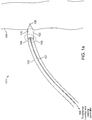
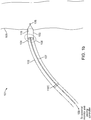
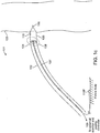
- FIGS 1a-1c are diagrammatic views of a wireless cardiac stimulation system 101, in accordance with an embodiment of the present invention.
- a delivery system 102 with a wireless receiver-stimulator (hereinafter also abbreviated as "R-S") 103 attached to the delivery system's distal tip 104 is inserted into the body of a patient. Typically, this would be through vascular access through the groin. Other entry sites sometimes chosen are found in the neck and are in general well known by physicians who practice such medical procedures.
- R-S wireless receiver-stimulator
- the delivery system 102 is positioned so that the R-S 103 at the distal tip 104 of the delivery system 102 is appropriately situated on a part of the heart wall 105 where the R-S 103 is to be attached/implanted.
- the insertion of the delivery system 102 may be facilitated by the use of a guidewire and/or a guiding catheter, as is known in the art.
- the movement of the delivery system 102 may be monitored fluoroscopically.
- the wireless R-S 103 comprises a cathode 106 and an anode 110 for stimulating patient tissue, with the cathode 106 located at the distal tip of the R-S 103.
- the cathode is intentionally designed with a smaller surface area relative to the anode. This leads to higher current densities at the cathode, resulting in tissue stimulation at the cathode.
- the term cathode and stimulation electrode are interchangeably used.
- the delivery system 102 comprises two temporary electrical connections between the R-S 103 and the delivery system 102: a first temporary electrical connection for establishing electrical contact with the cathode 106 and a second temporary electrical connection for establishing electrical contact with the anode 110.
- this may take the form of a single temporary electrical connection for establishing contact with the cathode 106 and the second electrical connection provided by an indifferent electrode 110C configured onto the delivery system (see Fig. 1b ) or an indifferent electrode 110P that is configured to be in electrical contact with the patient's body that is remote from the delivery system (see Fig. lc), wherein this second electrical connection is not a temporary electrical connection.
- the temporary electrical connections comprise electrical contact points between the proximal end of the R-S 103 and the distal end of the delivery system 102.
- the first temporary electrical connection (for the cathode) is between a first electrical contact point on the proximal end of the R-S 103 and a first electrical contact point on the distal end of the delivery system 102.
- the second temporary electrical connection (for the anode) is between a second electrical contact point on the proximal end of the R-S 103 and a second electrical contact point on the distal end of the delivery system 102.
- the temporary electrical connections provide conductive paths from the cathode 106 and anode 110 of the R-S 103 to an external monitor and pacing controller via conductive wires 107 routed through the delivery system 102, allowing externally controlled monitoring and pacing.
- any metal or conductive material on the cathode's temporary electrical connection contact point that remains exposed after the R-S 103 detaches from the delivery system 102 presents a potential for an alternate electrical path between the remaining conductive material and the anode. This could allow some or all of the stimulation current to bypass the desired path between the cathode 106 at the distal tip of the R-S 103 and the anode 110, at best reducing the efficiency of the wireless R-S 103 and at worst shunting energy away from the tissue and rendering the wireless R-S 103 ineffective.
- various disconnect mechanisms for the cathode's temporary electrical connection are disclosed herein which isolate one or more electrical contact points of the cathode's temporary electrical connection on the wireless R-S 103.
- One particular embodiment comprises using a non-hermetically sealed enclosure around the cathode's temporary electrical connection contact point on the R-S 103.
- Another embodiment comprises using magnetic and/or mechanical switches internal to the R-S 103 for electrically isolating the cathode's temporary electrical connection contact point from the cathode itself.
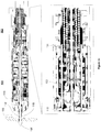
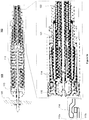
- FIG 2a shows a cross sectional view of a wireless R-S 103 attached to a delivery system 102, in accordance with an exemplary embodiment of the present invention.
- the wireless R-S 103 comprises a needle assembly 115 (also called an axle assembly), also shown in Figure 2b .
- the needle assembly 115 has a cathode 106 at its distal tip for stimulating the heart tissue.
- the needle assembly 115 is coated with an insulating layer, such as a thin ceramic layer, except at the cathode 106, at a segment 118a (shown in Fig.
- the needle assembly 115 further comprises a neck 119 configured to snap and disconnect as the delivery system 102 disengages from the R-S 103.
- Figure 2a shows the needle assembly 115 in a retracted state, with the cathode 106 fully within the R-S 103.
- the needle assembly 115 comprises one or more barbs 116 coupled proximal to the cathode 106.
- the barbs 116 are released when the needle assembly 115 is pushed sufficiently distally outward from the R-S 103 towards the heart wall 105.
- the distal portion of the delivery system 102 is shown in an enlarged view in the bottom panel of Fig. 2a .
- a conductive wire 123 in the delivery system 102 is coupled to a proximal segment 126 of the needle assembly 115 by a connecting collar 124.
- the outside of the wireless R-S 103 housing serves as an anode 110 for stimulating the heart tissue.
- the anode 110 may comprise only a portion of the R-S 103 housing, or it may comprise the entire outer surface of the R-S 103 housing.
- the R-S 103 preferably comprises an endothelial growth promoting covering 132 which does not insulate the surface of the anode 110.
- the covering 132 may comprise a polyester mesh.
- the delivery system 102 comprises a flexible outer sheath 133 connected to a rigid collar 125 with flexible extensions or fingers 114.
- the fingers 114 are held by tubular extension 121 radially outwards into place around an indentation 120 of the R-S 103, thereby detachably attaching the delivery system 102 to the R-S 103.
- the fingers 114 are made of a superelastic material, such as Nitinol, and configured to collapse radially inwards in the absence of a restrictive force and thereby release the R-S 103.
- the fingers 114 may comprise stainless steel, since it is contemplated that the strains experienced by such fingers 114 are small.
- a tubular extension 121 attached to the distal end of a retractable flexible wire coil 122 inside the sheath 133 provides such a restrictive force and holds the fingers 114 radially extended, preventing them from collapsing.
- the wire coil 122 and its tubular extension 121 are retracted, thereby allowing the fingers 114 to collapse and release the R-S 103.
- the wireless R-S 103 being disposed at the distal end of the delivery system 102, comes close to or contacts the heart wall 105 such that the cathode 106 is in electrical contact with the heart wall 105.
- the anode 110 may be in contact with the heart wall 105 or it may remain within the chamber of the heart.
- any other indifferent electrode (110C or 110P) e.g., one positioned on the outer sheath of the delivery system 102 or placed on the patient's body remote from the delivery system, respectively, may be used as an anode.
- the wireless R-S 103 can thus be repositioned by the delivery system 102 to assess electrical activity at various locations of the heart wall 105 using the cathode 106 and the anode 110 or indifferent electrode 110C or 110P.
- contact points 112a and 112b are shown apart in the enlarged view of Figure 2a for illustration purposes only, as they are actually in contact in the particular configuration of the R-S 103 shown in Figure 2a .
- One or more conductive wires coupled to the fingers 114 provide a conductive path from the anode 110 to an external monitor or controller via the delivery system 102.
- these wires may also serve as articulation control wires.
- the rigid collar 125 makes electrical contact with the tubular extension 121 of flexible coil 122 which in turn provides a conductive path from anode 110 to an external monitor or controller via the delivery system 102.
- the R-S 103 and the fingers 114 are gold plated at the temporary electrical contact points 112 in order to provide increased electrical conductivity.
- a direct temporary electrical connection is provided from the delivery system 102 to the anode 110 as described above, it is contemplated that a direct connection from the delivery system 102 to the cathode 106 located at the distal tip of the wireless R-S 103 may provide alternative current paths, or may impose complications in manufacturing, cost or reliability.
- a temporary electrical connection between the distal end of the delivery system 102 and the proximal end of the wireless R-S 103 housing is disclosed herein that provides a conductive path from the distal tip of the delivery system 102 via the needle assembly 115 to the cathode 106.
- this temporary electrical connection to the cathode 106 comprises an enclosure 117 configured around the neck segment 119 of the needle assembly 115. At its distal end, the enclosure 117 is tightly coupled to the needle assembly 115. Internally, the enclosure 117 comprises a seal 127 around the proximal segment 126 of the needle assembly 115.
- the seal 127 may be made of silicone, rubber or other flexible insulating material.
- the seal 127 need not necessarily be hermetic, but it is configured to provide high enough electrical resistance, for example in excess of 10,000 ohms, between the detached temporary electrical connection and the heart wall 105 or the fluid within the heart chamber to allow substantially any electrical current applied to the needle 115 to flow through the electrical path of the cathode 106 to the anode 110.
- the conductive wire 123 is retracted into the delivery system 102, breaking the needle assembly 115 at the neck 119 and removing the proximal segment 126 of the needle assembly 115 from the enclosure 117.
- the two end points of the broken neck represent the two temporary electrical contact points for the temporary electrical connection between the catheter and the cathode.
- the seal 127 closes in around the hole left by the removed proximal segment 126, electrically isolating the remaining part of the needle assembly 115 (which includes the cathode temporary electrical connection contact point on the R-S 103) inside the sealed enclosure 117 from patient fluid and tissue.
- the distal mechanism of the catheter is such that the extension 130 is limited in its travel so that movement of the wire coil 131 cannot move the needle assembly 115 into its triggered state, thereby obviating requirements for precise motion in the handle of the delivery system 102.
- a wire coil 129 and its extension 128 have pushed the needle assembly 115 further out, releasing the barbs 116 and allowing the R-S 103 to securely attach itself to the heart wall 105.
- the catheter sheath 133 and wire coils 122 and 131 are retracted and/or the wire coil 129 and wire 123 are extended, leaving the R-S 103 tethered to the wire 123 and in contact or in proximity with the tubular extension 128 of the wire coil 129.
- the tethered state allows the R-S 103 to remain attached to the delivery system 102 and retrievable, while being only connected by a very flexible coupling. This flexibility allows the R-S 103 to move with the heart wall independently of the delivery system 102, demonstrating under flouroscopic visualization that the R-S 103 is reliably attached to the heart wall 105.
- the delivery system 102 and the tethering mechanism can be moved by small amounts, changing the degree of slack without eliminating slack. Such movement may demonstrate that the attachment point of the R-S 103 to the heart wall remains fixed while the orientation of the R-S 103 with respect to the heart wall varies, further indicating reliable attachment.
- Figure 2g (“tether broken state"), the wire 123 is retracted while the wire coil 129 and its extension 128 exert a resistance against the R-S 103 and prevent it from being pulled along. This causes the needle assembly 115 to break at the neck 119.
- the two end points of the broken neck 119 represent the two temporary electrical contact points for the temporary electrical connection between the delivery system 102 and the cathode 106, with contact point 134a representing the electrical contact point at the distal end of the delivery system 102 and contact point 134b representing the electrical contact point at the proximal end of the R-S 103.
- the wire 123 continues to retract, it removes with it the broken proximal piece 126 of the needle assembly 115 from the enclosure 117. Seal 127 closes following the removal of proximal piece 126, forming an electrical isolation between needle 115 and the fluid surrounding the proximal end of the R-S 103.
- Figure 2h (“delivered state”), the wire coil 129 and its extension 128 are retracted into the delivery system 102 along with the wire 123, leaving the R-S 103 delivered in the heart wall 105.
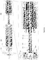
- FIG. 3 is a diagrammatic view of a delivery system 102 and its handle 141, in accordance with an embodiment of the present invention.
- the delivery system 102 is configured for use in the cardiovascular system of a patient and configured to be compatible with standard transvascular tools, such as introducers and guiding sheaths, and conventional techniques related to the operation of such tools.
- the delivery system 102 comprises one or more safety mechanisms, interlocks, or indicators configured to prevent inadvertent attachment or release of the R-S 103.
- the delivery system 102 provides signal interconnect with an external monitor and pacing controller to facilitate location selection during an implant procedure by collecting local EGM signals, performing direct electrical pacing of the heart via electrical connections to one or more of the electrodes of the implantable R-S 103 device, and evaluating operational efficiency of the R-S 103.
- the delivery system shaft 140 is formed from polymer tubing. Conductive wires 143, deflection wires 147 and safety release interlock wires 146 are routed within the shaft 140.
- a proximal handle assembly 141 comprises a deflection control mechanism 142, a safety interlock release mechanism 145, and shrouded electrical connectors 144 that terminate the conductive wires 143 and permit driving the R-S 103 electrodes directly with an externally-generated electrical pacing pulse, as well as monitoring of cardiac EGM signals at the R-S 103 electrodes.
- the delivery system 102 is configured to attach the R-S in the left ventricle (LV) by prolapsing the shaft 140 in the aortic arch and advancing through the aortic valve of the heart atraumatically, thereby allowing access to targeted endocardial locations within the LV.
- the distal portion of the delivery system 102 is deflectable in one plane in at least one direction, through the handle-mounted deflection control system.
- the deflection control system holds a desired deflection angle.
- the delivery system can be configured to attach the R-S in any heart chamber or on the epicardial surface of the heart or within the vasculature of the heart.
- the delivery system 102 and/or R-S 103 may comprise one or more radiopaque markers at the distal end to allow fluoroscopic confirmation of the state of R-S 103 deployment.
- the markers are configured to clearly differentiate between various stages of deployment, possibly including but not limited to: a) cathode retracted, b) cathode extended, c) attachment tines deployed, d) R-S 103 released, e) tether advanced, f) tether broken, and g) tether retracted.
- the delivery system 102 comprises a control mechanism to extend and retract the needle assembly 115 of the R-S 103.
- the control mechanism includes a safety mechanism to prevent accidental extension or retraction of the needle assembly 115.
- the control mechanism and/or the R-S 103 allows for locking the needle assembly 115 into the desired position (retracted or injected as shown in exemplary Figures 2a and 2c ).
- the delivery system 102 comprises a control mechanism to activate the attachment mechanism of the R-S 103, as shown in exemplary Figure 2d .
- This control mechanism and/or the R-S 103 design includes an interlock to prevent deployment of the R-S 103 attachment mechanism unless the cathode 106 is extended.
- the control mechanism to activate the attachment mechanism comprises multiple or multi-stage safety mechanisms to prevent inadvertent activation.
- the delivery system 102 also comprises a control mechanism to release the R-S 103, as shown in exemplary Figures 2e-2h .
- the control mechanism and/or the R-S 103 design include an interlock to prevent release of the R-S 103 unless the attachment mechanism has been deployed.
- the control mechanism to release the R-S 103 incorporates multiple or multi-stage safety mechanisms to prevent inadvertent activation.
- the delivery system 102 and/or R-S 103 comprise reliable means to verify a secure implantation prior to permanent release.
- the delivery system 102 also comprises a control mechanism to tether out (extend) the R-S 103 away from the main body of the delivery system 102, as shown in exemplary Figure 2f .
- the control mechanism and/or the R-S 103 design include an interlock to prevent tethering out of the R-S 103 unless the release mechanism has been deployed.
- the control mechanism to tether the R-S 103 incorporates multiple or multi-stage safety mechanisms to prevent inadvertent tether extension.
- the delivery system 102 and/or R-S 103 comprise reliable means to verify a secure implantation prior to detaching the tether.
- the delivery system 102 and the R-S 103 are removable from the vasculature with the tether extended or with the tether retracted.
- the delivery system 102 also comprises a control mechanism to detach the tether and disconnect the temporary electrical connection from the R-S 103, as shown in exemplary Figure 2g .
- the control mechanism detaches and disconnects, in alternative embodiments separate mechanisms may be applied to disconnect and detach.
- the control mechanism and/or the R-S 103 designs include an interlock to prevent disconnecting and detaching the tether of the delivery system 102 unless the release mechanism has been deployed.
- the control mechanism to disconnect the temporary electrical connection and detach the tether from the R-S 103 incorporates multiple or multi-stage safety mechanisms to prevent inadvertent detachment.
- the delivery system 102 and/or R-S 103 comprise reliable means to verify a secure implantation prior to disconnecting the temporary electrical connection and detaching the tether.
- the delivery system 102 is removable from the vasculature with the tether extended or with the tether retracted.
- the delivery system 102 is removable from the vasculature by manual withdrawal through an introducer. Any enlargement or protrusion from the delivery system 102 as part of the R-S 103 release mechanism is retractable and/or reversible to allow removal.
- the delivery system 102 comprises conventional means to protect against accidental release of air into the vasculature or heart chamber before and after release of the R-S 103.
- the delivery system 102 is mated with an R-S 103 prior to packaging.
- the delivery system 102 and R-S 103 are mated and packaged with the cathode 106 locked in a retracted state.
- a delivery system 102 with a pre-mated R-S 103 are packaged in a single-use sterile pouch or tray, and a catheter extension cable is packaged in the same single-use sterile pouch or tray with the delivery system 102 and R-S 103.
- FIG. 4 is a flow diagram illustrating a method for implantation of a receiver-stimulator into the heart, in accordance with an embodiment of the present invention.
- an implantable wireless R-S 103 in retracted state is delivered into the heart at a candidate pacing location using a delivery system 102.
- the heart's electrical activity is monitored at the location in the heart as sensed by the cathode 106 in an injected state and an indifferent electrode, possibly anode 110 of the R-S 103.
- the heart tissue is stimulated at step 456 using electrical stimulation energy from an external pacing controller delivered to the tissue through the cathode 106 in an injected state and an anode, possibly anode 110 of the R-S 103, thereby allowing determination of an acceptable electrical pacing threshold at the location prior to permanent attachment of the R-S 103 to the heart wall. If the pacing threshold is not acceptable, the R-S 103 is repositioned and the above steps are repeated until an acceptable pacing threshold is found.
- a wireless controller-transmitter (not shown) delivers acoustic energy to the wireless R-S 103, which in turn delivers electrical energy converted by the R-S 103 from the acoustic energy to the heart tissue through the cathode 106 in an injected state and necessarily the anode 110.
- an external monitor connected at least to the R-S 103 cathode 106 via the temporary electrical connection and to an indifferent electrode, possibly the anode 110 via its temporary electrical connections or alternatively an indifferent electrode 110C on the delivery system 102 or the indifferent electrode 110P, monitors and quantifies the delivered electrical energy at step 462 to determine the efficiency of conversion of acoustic energy to electrical energy by the R-S 103 at the current location and position in the heart.
- electromagnetic energy e.g., RF
- RF electromagnetic energy
- the delivered electrical energy is at pacing strength to stimulate the tissue and the EGM generated by the stimulation of heart tissue is monitored using the temporary electrical connections to the cathode 106 and anode 110 to determine acoustic to electrical conversion efficiency.
- the delivered electrical energy is not at pacing/stimulation strength, but instead is at a level below the stimulation threshold; hence conversion efficiency can be gauged even at lower energy levels.
- electrical monitoring via the temporary electrical connections to the cathode 106 and an anode, possibly the anode 110 via its temporary electrical connections or alternatively an indifferent electrode 110C on the delivery system 102 or indifferent electrode 110P that is remote from the delivery system indicates the level of electrical energy generated by the R-S 103. A comparison of this level of generated electrical energy against the amount of acoustic energy transmitted to the R-S 103 indicates the conversion efficiency of the R-S 103.
- the R-S 103 is attached to the heart wall in the triggered state, and at step 468 the temporary electrical connections to the cathode 106 and anode 110 are disconnected using a disconnect mechanism as the R-S 103 goes through the sequence of released state, tethered state, tether broken state, and delivered state, as described above in Figures 2e-2h .
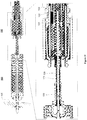
- FIG. 5a is a diagrammatic view of a sealed disconnect mechanism 108 of a wireless R-S 103, in accordance with an embodiment of the present invention, providing a temporary electrical connection between an electrical contact at a proximal position of the R-S 103 and an electrical contact at a distal position of the catheter assembly 102.
- the proximal end of the wireless R-S 103 comprises a connector receptacle 203 as part of a needle assembly 115.
- the proximal tip of the connector receptacle 203 represents the electrical contact at a proximal position of the R-S 103.
- the needle assembly 115 is insulated from the anode 110 by an insulator 205.
- the insulator 205 may comprise ceramic, glass, or other insulating material, and additionally creates a hermetic seal between the body of the R-S 103 and the connector 203.
- the connector receptacle 203 is at the proximal end of the needle assembly 115 and is electrically connected to the cathode 106 via the needle assembly 115.
- a seal 206 covers the connector receptacle 203 and comprises a hole or slit 207 to allow the conductive wire 123 of the delivery system 102 to pass through and electrically connect to the cathode 106 (via the connection to the connector receptacle 203).
- the distal tip of the conductive wire 123 represents the electrical contact at a distal position of the catheter assembly 102. This is shown in Figure 5b .
- the seal 206 may comprise silicone, rubber or other flexible insulating material.
- the seal 206 is compressed so that the hole or slit 207 is forced closed when the wire 123 is withdrawn, thereby isolating the connector receptacle 203 and the needle assembly 115 from patient fluid or tissue.
- the seal 206 need not necessarily be hermetic, but it is configured to provide high enough electrical resistance through the temporary electrical path to the connector receptacle 203 to allow substantially any electrical current to flow through the electrical path of the cathode 106 to the anode 110.
- FIG. 5c is a diagrammatic view of a magnetically operated disconnect mechanism, in accordance with a first such embodiment of the present invention.
- This embodiment comprises a magnetically operated switch 211 internal to the R-S 103.
- the delivery system 102 comprises a magnet 210 at its distal tip, and a magnetic metal disk 212 is attracted to the feed-through 204 by the catheter magnet 210.
- the magnet 210 on the distal end of the delivery system 102 holds the switch 211 closed when the wireless R-S 103 is attached to the delivery system 102, bringing the magnetic metal disk 212, which is in contact with the cathode 106, into contact with a feed-through 204.
- One or more springs 213 push the disk 212 away and hold the switch 211 open when the catheter magnet 210 detaches from R-S 103 and is withdrawn, at which point the switch 211 opens and the temporary electrical connection from the cathode 106 to the feed-through 204 is disconnected.
- Figure 5c shows the delivery system 102 removed and the switch 211 open.
- FIG. 5d is a diagrammatic view of a magnetically operated disconnect mechanism, in accordance with a second such embodiment of the present invention.
- the magnetically operated switch 220 is a "reed" switch.
- the reed switch 220 comprises a magnet 221 on the end of the reed lever 222.
- the reed lever 222 could be made of a magnetic metal, eliminating the need for magnet 221.
- the magnet 221 is attracted to the feed-through 204 by a catheter magnet 210 and closes the switch 220 when the delivery system 102 is attached to the wireless R-S 103.
- the reed switch 220 springs back when the catheter magnet 210 is detached from R-S 103 and is withdrawn, thereby causing electrical disconnection.
- FIGS 5e-f are diagrammatic views of a disconnect mechanism using bellows, in accordance with an embodiment of the present invention.
- the disconnect mechanism comprises bellows 301 comprising an inside lead 304 on the distal end of the bellows 301 and an outside lead 305 on the proximal end of the bellows 301.
- the inside lead 304 is electrically connected to the cathode 106 via the needle assembly.
- the outside lead 305 may comprise a proximal segment for connecting with the conductive wire 123 of the catheter via a connecting collar, similar to the embodiment described in Figures 2a-g , and a mechanism for mechanical disconnection.
- the proximal segment, needle assembly, and connecting collar are not shown in Figures 5e-f , but they are analogous to those described above with reference to Figures 2a-g .
- the bellows 301 is initially configured such that the outside lead 305 is in electrical contact with the inside lead 304 at the electrical contact point 302 as shown in Figure 5e , thereby providing a temporary electrical connection between the conductive wire 123 of the delivery system 102 and the cathode 106.
- the bellows 301 stretches when the delivery system 102 is retracted and pulled away from the wireless R-S 103, thereby disconnecting the temporary electrical connection to the cathode 106, as shown in Figure 5f .
- the delivery system 102 is retracted, it also detaches the delivery system 102 from the R-S 103.
- the outside lead 305 is electrically isolated from the cathode 106.
- the insulator 205 is hermetically connected to the enclosure of the wireless R-S 103.
- FIGS 5g-h are diagrammatic views of a disconnect mechanism using a conductive dome structure, in accordance with an embodiment of the present invention.
- the disconnect mechanism comprises an inside lead 313 on the distal end of the disconnect mechanism and a conductive dome structure 310 with a feature 314 on the proximal end of the disconnect mechanism.
- the inside lead 313 is electrically connected to the cathode 106 via the needle assembly.
- the conductive dome structure 310 is housed within an insulating cup 311.
- the insulating cup 311 comprises ceramic or other insulating material.
- the feature 314 may comprise a proximal segment for connecting with the conductive wire 123 of the catheter via a detachable connecting collar, similar to the embodiment described in Figures 2a-g .
- the proximal segment, needle assembly, and connecting collar are not shown in Figures 5e-f , but they are analogous to those described above with reference to Figures 2a-g .
- the conductive dome structure 310 is initially configured such that it is in electrical contact with the inside lead 313 at the electrical contact point 312 as shown in Figure 5g , thereby providing an electrical path between the conductive wire 123 of the delivery system 102 and the cathode 106.
- the conductive dome structure 310 pops out when the delivery system 102 is retracted and pulled away from the wireless R-S 103, thereby disconnecting the temporary electrical connection to the cathode 106, as shown in Figure 5h .
- the delivery system 102 is retracted, it detaches the delivery system 102 from the R-S 103.
- the conductive dome structure 310 is electrically isolated from the cathode 106.
- the insulating cup 311 is hermetically connected to the enclosure of the wireless R-S 103, the inside lead 313, and the conductive dome structure 310, as shown in Figure 5h .
- the disconnect mechanism comprises a fuse internal to the R-S 103. Once a suitable implant location has been determined and the R-S 103 has been attached to the heart, the fuse is opened (blown) by delivering sufficient current through the conductive wire 123 of the delivery system 102. The opened fuse disconnects the temporary electrical connection to the cathode 106.
- the disconnect mechanism may comprise an electronic switch internal to the R-S 103 which when activated disconnects the temporary electrical connection to the cathode 106.
Landscapes
- Health & Medical Sciences (AREA)
- Life Sciences & Earth Sciences (AREA)
- Engineering & Computer Science (AREA)
- Biomedical Technology (AREA)
- Animal Behavior & Ethology (AREA)
- General Health & Medical Sciences (AREA)
- Public Health (AREA)
- Veterinary Medicine (AREA)
- Nuclear Medicine, Radiotherapy & Molecular Imaging (AREA)
- Radiology & Medical Imaging (AREA)
- Cardiology (AREA)
- Heart & Thoracic Surgery (AREA)
- Biophysics (AREA)
- Physics & Mathematics (AREA)
- Pathology (AREA)
- Medical Informatics (AREA)
- Molecular Biology (AREA)
- Surgery (AREA)
- Physiology (AREA)
- Electrotherapy Devices (AREA)
Claims (17)
- Gerät, das Folgendes umfasst:
einen Empfänger-Stimulator (103), der unter Verwendung eines Zuführungssystems (102) in das Herz eines Patienten implantierbar und so konfiguriert ist, dass er geregelte akustische Energie von einem Controller-Sender empfängt und die akustische Energie in elektrische Energie umwandelt, wobei der Empfänger-Stimulator (103) Folgendes umfasst:eine erste Elektrode (106), eine zweite Elektrode (110) und einen elektrischen Kontakt (134b, 203, 204, 302, 310), der mit der ersten Elektrode (106) elektrisch verbunden ist, wobei die erste und die zweite Elektrode (106, 110) so konfiguriert sind, dass sie die elektrische Energie zu einer Stelle im Herzen liefern;einen elektrischen Verbinder, der so konfiguriert ist, dass er eine vorübergehende elektrische Verbindung zwischen dem elektrischen Kontakt (134b, 203, 204, 302, 310) und dem Zuführungssystem (102) bereitstellt; undeinen Trennmechanismus (108) zum Trennen der vorübergehenden elektrischen Verbindung, wobei der Trennmechanismus (108):eine Dichtung (127, 206) beinhaltet, die so konfiguriert ist, dass sie den elektrischen Kontakt (134b, 203) gegen Patientengewebe elektrisch isoliert, wenn der Empfänger-Stimulator (103) vom Zuführungssystem (102) abgelöst wird, oderso konfiguriert ist, dass er den elektrischen Kontakt (204, 302, 310) von der ersten Elektrode (106) elektrisch trennt, wenn der Empfänger-Stimulator (103) vom Zuführungssystem (102) abgelöst wird;wobei der elektrische Verbinder so konfiguriert ist, dass er über das Zuführungssystem (102) mit einem externen Monitor verbunden wird. - Gerät nach Anspruch 1, wobei der Empfänger-Stimulator (103) lösbar an einem distalen Ende eines Katheter-basierten Zuführungssystems (102) angebracht werden kann.
- Gerät nach Anspruch 1, wobei der Empfänger-Stimulator (103) so konfiguriert ist, dass er das Herz mittels der ersten und zweiten Elektrode stimuliert, wobei die zweite Elektrode (110) eine Anode (110) und die erste Elektrode (106) eine Kathode (106) ist, und wobei der elektrische Verbinder so konfiguriert ist, dass er eine vorübergehende elektrische Verbindung zwischen der Kathode (106) und dem Zuführungssystem oder zwischen der Anode (110) und dem Zuführungssystem (102) herstellt.
- Gerät nach Anspruch 1, wobei der Empfänger-Stimulator (103) so konfiguriert ist, dass er das Herz unter Verwendung der ersten und zweiten Elektrode stimuliert, wobei die zweite Elektrode (110) eine Anode (110) und die erste Elektrode (106) eine Kathode (106) ist, und wobei der elektrische Verbinder ein erster elektrischer Verbinder ist, der so konfiguriert ist, dass er eine vorübergehende elektrische Verbindung zwischen der Kathode (106) und dem Zuführungssystem (102) herstellt, und ferner einen zweiten elektrischen Verbinder umfasst, der so konfiguriert ist, dass er eine vorübergehende elektrische Verbindung zwischen der Anode (110) und dem Zuführungssystem (102) herstellt.
- Gerät nach Anspruch 3 oder 4, das ferner eine indifferente Elektrode (110C oder 110P) umfasst, die für einen elektrischen Kontakt mit dem Patienten konfiguriert ist; wobei die Kathode (106) und die indifferente Elektrode (110C oder 110P) zum Überwachen der elektrischen Herzaktivität und zum Stimulieren des Herzens konfiguriert sind.
- Gerät nach Anspruch 4, wobei der Trennmechanismus (108) eine Dichtung (127, 206) beinhaltet, die so konfiguriert ist, dass sie den elektrischen Kontakt (134b, 203) gegen Patientengewebe elektrisch isoliert, wenn der Empfänger-Stimulator (103) vom Zuführungssystem (102) abgelöst wird, und wobei der elektrische Verbinder so konfiguriert ist, dass er eine vorübergehende elektrische Verbindung zwischen dem elektrischen Kontakt (134b, 203) an einer ersten proximalen Position des Empfänger-Stimulators (103) und einem weiteren elektrischen Kontakt an einer ersten distalen Position der Zuführungssystembaugruppe (102) herstellt, und wobei der Trennmechanismus (108) ferner so konfiguriert ist, dass er den elektrischen Kontakt (134b, 203) an der ersten proximalen Position des Empfänger-Stimulators (103) gegen einen leitfähigen Pfad zum Patienten isoliert.
- Gerät nach Anspruch 6, wobei der Trennmechanismus (108) einen Verbinderbehälter (203) umfasst, um es zu ermöglichen, dass ein Leiterdraht von der Zuführungssystembaugruppe (102) zum elektrischen Kontakt (134b, 203) verläuft, und wobei die Dichtung (127, 206) eine komprimierte Dichtung ist, die so konfiguriert ist, dass sie den Verbinderbehälter (203) schließt und abdeckt, wenn der Leiterdraht herausgezogen wird.
- Gerät nach Anspruch 6, wobei der Trennmechanismus (108) ferner so konfiguriert ist, dass er den elektrischen Kontakt (134b, 203) an der ersten proximalen Position des Empfänger-Stimulators (103) gegen die Kathode (106) elektrisch isoliert.
- Gerät nach Anspruch 1, wobei der Trennmechanismus (108) so konfiguriert ist, dass er den elektrischen Kontakt (204) von der ersten Elektrode (106) elektrisch trennt, wenn der Empfänger-Stimulator (103) vom Zuführungssystem (102) abgelöst wird, und wobei der Trennmechanismus (108) einen magnetisch betätigten Schalter (211) in dem Empfänger-Stimulator (103) umfasst.
- Gerät nach Anspruch 9, wobei der magnetisch betätigte Schalter (211) so konfiguriert ist, dass er durch einen Magneten (210) am distalen Ende der Zuführungssystembaugruppe (102) geschlossen gehalten wird, und wobei der Schalter (211) so konfiguriert ist, dass er durch eine oder mehrere Federn (213) beim Ablösen des Zuführungssystems (102) geöffnet wird, um den elektrischen Kontakt (204) von der ersten Elektrode zu trennen.
- Gerät nach Anspruch 9, wobei der magnetisch betätigte Schalter (211) ein Reedschalter (220) ist, der so konfiguriert ist, dass er von einem Magneten (221) am distalen Ende der Zuführungssystembaugruppe (102) geschlossen gehalten wird, und wobei der Reedschalter (220) so konfiguriert ist, dass er sich beim Ablösen des Zuführungssystems (102) öffnet, um den elektrischen Kontakt (204) von der ersten Elektrode (106) zu trennen.
- Gerät nach Anspruch 1, wobei der Trennmechanismus (108) so konfiguriert ist, dass er den elektrischen Kontakt (302) von der ersten Elektrode (106) elektrisch trennt, wenn der Empfänger-Stimulator (103) vom Zuführungssystem (102) abgelöst wird, und wobei der Trennmechanismus (108) einen Balg (301) umfasst, der so konfiguriert ist, dass er sich dehnt, wenn das Zuführungssystem (102) vom Empfänger-Stimulator (103) abgelöst wird, wodurch der elektrische Kontakt (302) von der ersten Elektrode (106) getrennt wird.
- Gerät nach Anspruch 12, wobei der Balg (301) so konfiguriert ist, dass er komprimiert gehalten wird, während er mit dem Zuführungssystem (102) verbunden ist, und aufspringt, wenn er vom Zuführungssystem gelöst wird.
- Gerät nach Anspruch 1, wobei der Trennmechanismus (108) so konfiguriert ist, dass er den elektrischen Kontakt (310) von der ersten Elektrode (106) elektrisch trennt, wenn der Empfänger-Stimulator (103) vom Zuführungssystem (102) abgelöst wird, und wobei der Trennmechanismus (108) eine leitfähige Kuppelstruktur (310) aufweist, die so konfiguriert ist, dass sie sich nach außen wölbt, wenn das Zuführungssystem (102) vom Empfänger-Stimulator (103) abgelöst wird, wodurch der elektrische Kontakt (310) von der ersten Elektrode (106) getrennt wird.
- Gerät nach Anspruch 1, wobei der Trennmechanismus (108) eine Sicherung oder einen elektronischen Schalter umfasst, so konfiguriert, dass sie/er den elektrischen Kontakt (134b, 203, 204, 302, 310) bei Aktivierung von der ersten Elektrode (106) trennt.
- System, das das Gerät nach Anspruch 1 und das Zuführungssystem (102) umfasst, wobei das Zuführungssystem einen Katheter mit einem proximalen Ende und einem distalen Ende umfasst; wobei der Empfänger-Stimulator (103) ablösbar am distalen Ende des Katheters angebracht ist; wobei die erste Elektrode (106) eine Kathode (106) und die zweite Elektrode (110) eine Anode (110) ist; wobei die Kathode (106) und die Anode (110) so konfiguriert sind, dass sie in elektrischem Kontakt mit dem Patienten stehen, um das Herz zu stimulieren; wobei der elektrische Verbinder eine erste vorübergehende elektrische Verbindung zwischen der Kathode (106) und dem Katheter herstellt und sich durch den Katheter erstreckt; wobei der Trennmechanismus (108) so konfiguriert ist, dass er die erste vorübergehende elektrische Verbindung trennt; wobei das Gerät eine indifferente Elektrode (110C oder 110P) umfasst, wobei die indifferente Elektrode (110C oder 110P) so konfiguriert ist, dass sie in elektrischem Kontakt mit dem Patienten ist; wobei die Kathode (106) und die indifferente Elektrode (110C oder 110P) so konfiguriert sind, dass sie die elektrische Herzaktivität überwachen und das Herz stimulieren.
- System nach Anspruch 16, das ferner einen zweiten elektrischen Verbinder umfasst, der so konfiguriert ist, dass er eine zweite vorübergehende elektrische Verbindung zwischen der Anode (110) und dem Katheter bereitstellt, wobei sich die elektrische Verbindung durch den Katheter erstreckt; wobei das Gerät ferner einen zweiten Trennmechanismus umfasst, um die zweite vorübergehende elektrische Verbindung zu trennen; wobei die Kathode (106) und die Anode (110) so konfiguriert sind, dass sie die elektrische Herzaktivität überwachen und das Herz stimulieren.
Applications Claiming Priority (2)
| Application Number | Priority Date | Filing Date | Title |
|---|---|---|---|
| US3933508P | 2008-03-25 | 2008-03-25 | |
| PCT/US2009/037978 WO2009120636A1 (en) | 2008-03-25 | 2009-03-23 | Temporary electrode connection for wireless pacing systems |
Publications (3)
| Publication Number | Publication Date |
|---|---|
| EP2265166A1 EP2265166A1 (de) | 2010-12-29 |
| EP2265166A4 EP2265166A4 (de) | 2011-11-02 |
| EP2265166B1 true EP2265166B1 (de) | 2020-08-05 |
Family
ID=41114294
Family Applications (1)
| Application Number | Title | Priority Date | Filing Date |
|---|---|---|---|
| EP09725046.8A Active EP2265166B1 (de) | 2008-03-25 | 2009-03-23 | Vorübergehende elektrodenverbindung für drahtlose schrittmachersysteme |
Country Status (3)
| Country | Link |
|---|---|
| US (4) | US9283392B2 (de) |
| EP (1) | EP2265166B1 (de) |
| WO (1) | WO2009120636A1 (de) |
Families Citing this family (152)
| Publication number | Priority date | Publication date | Assignee | Title |
|---|---|---|---|---|
| US7532933B2 (en) | 2004-10-20 | 2009-05-12 | Boston Scientific Scimed, Inc. | Leadless cardiac stimulation systems |
| US8649875B2 (en) | 2005-09-10 | 2014-02-11 | Artann Laboratories Inc. | Systems for remote generation of electrical signal in tissue based on time-reversal acoustics |
| US7848823B2 (en) | 2005-12-09 | 2010-12-07 | Boston Scientific Scimed, Inc. | Cardiac stimulation system |
| US8406901B2 (en) | 2006-04-27 | 2013-03-26 | Medtronic, Inc. | Sutureless implantable medical device fixation |
| US8078283B2 (en) * | 2006-06-20 | 2011-12-13 | Ebr Systems, Inc. | Systems and methods for implantable leadless bone stimulation |
| US7840281B2 (en) | 2006-07-21 | 2010-11-23 | Boston Scientific Scimed, Inc. | Delivery of cardiac stimulation devices |
| US8644934B2 (en) | 2006-09-13 | 2014-02-04 | Boston Scientific Scimed Inc. | Cardiac stimulation using leadless electrode assemblies |
| US9492657B2 (en) | 2006-11-30 | 2016-11-15 | Medtronic, Inc. | Method of implanting a medical device including a fixation element |
| US8718773B2 (en) | 2007-05-23 | 2014-05-06 | Ebr Systems, Inc. | Optimizing energy transmission in a leadless tissue stimulation system |
| JP5153892B2 (ja) * | 2008-02-07 | 2013-02-27 | カーディアック ペースメイカーズ, インコーポレイテッド | 無線組織電気刺激 |
| EP2265166B1 (de) | 2008-03-25 | 2020-08-05 | EBR Systems, Inc. | Vorübergehende elektrodenverbindung für drahtlose schrittmachersysteme |
| US10112045B2 (en) | 2010-12-29 | 2018-10-30 | Medtronic, Inc. | Implantable medical device fixation |
| US20120172891A1 (en) * | 2010-12-29 | 2012-07-05 | Medtronic, Inc. | Implantable medical device fixation testing |
| US9775982B2 (en) | 2010-12-29 | 2017-10-03 | Medtronic, Inc. | Implantable medical device fixation |
| US9220906B2 (en) | 2012-03-26 | 2015-12-29 | Medtronic, Inc. | Tethered implantable medical device deployment |
| US9717421B2 (en) | 2012-03-26 | 2017-08-01 | Medtronic, Inc. | Implantable medical device delivery catheter with tether |
| US10485435B2 (en) | 2012-03-26 | 2019-11-26 | Medtronic, Inc. | Pass-through implantable medical device delivery catheter with removeable distal tip |
| US9854982B2 (en) | 2012-03-26 | 2018-01-02 | Medtronic, Inc. | Implantable medical device deployment within a vessel |
| US9339197B2 (en) | 2012-03-26 | 2016-05-17 | Medtronic, Inc. | Intravascular implantable medical device introduction |
| US9833625B2 (en) | 2012-03-26 | 2017-12-05 | Medtronic, Inc. | Implantable medical device delivery with inner and outer sheaths |
| US9351648B2 (en) | 2012-08-24 | 2016-05-31 | Medtronic, Inc. | Implantable medical device electrode assembly |
| US9055930B2 (en) * | 2012-12-17 | 2015-06-16 | Cook Medical Technologies Llc | Device for preparing an implanted medical apparatus for extraction |
| US10071243B2 (en) | 2013-07-31 | 2018-09-11 | Medtronic, Inc. | Fixation for implantable medical devices |
| WO2015023486A1 (en) | 2013-08-16 | 2015-02-19 | Cardiac Pacemakers, Inc. | Delivery devices and methods for leadless cardiac devices |
| US9480850B2 (en) | 2013-08-16 | 2016-11-01 | Cardiac Pacemakers, Inc. | Leadless cardiac pacemaker and retrieval device |
| US10722723B2 (en) | 2013-08-16 | 2020-07-28 | Cardiac Pacemakers, Inc. | Delivery devices and methods for leadless cardiac devices |
| CN105916544B (zh) | 2013-08-16 | 2019-11-12 | 心脏起搏器股份公司 | 无引线心脏起搏设备 |
| WO2015023474A1 (en) | 2013-08-16 | 2015-02-19 | Cardiac Pacemakers, Inc. | Leadless cardiac pacemaker and retrieval device |
| US9492674B2 (en) | 2013-08-16 | 2016-11-15 | Cardiac Pacemakers, Inc. | Leadless cardiac pacemaker with delivery and/or retrieval features |
| US9393427B2 (en) | 2013-08-16 | 2016-07-19 | Cardiac Pacemakers, Inc. | Leadless cardiac pacemaker with delivery and/or retrieval features |
| US10842993B2 (en) | 2013-08-16 | 2020-11-24 | Cardiac Pacemakers, Inc. | Leadless cardiac pacing devices |
| US9592391B2 (en) | 2014-01-10 | 2017-03-14 | Cardiac Pacemakers, Inc. | Systems and methods for detecting cardiac arrhythmias |
| JP2017501839A (ja) | 2014-01-10 | 2017-01-19 | カーディアック ペースメイカーズ, インコーポレイテッド | 医療装置間の優れた通信のための方法およびシステム |
| US10080887B2 (en) | 2014-04-29 | 2018-09-25 | Cardiac Pacemakers, Inc. | Leadless cardiac pacing devices including tissue engagement verification |
| CN106456968B (zh) | 2014-04-29 | 2018-11-30 | 心脏起搏器股份公司 | 具有取回特征的无引线心脏起搏器 |
| EP3185952B1 (de) | 2014-08-28 | 2018-07-25 | Cardiac Pacemakers, Inc. | Implantierbares herzrhythmussystem und ein zugehöriges verfahren zur auslösung einer austastperiode durch ein zweites gerät |
| CN106852124A (zh) | 2014-10-22 | 2017-06-13 | 心脏起搏器股份公司 | 用于无引线心脏设备的递送设备与方法 |
| EP3209377B1 (de) | 2014-10-22 | 2019-03-06 | Cardiac Pacemakers, Inc. | Freisetzungsvorrichtungen und verfahren für elektrodenlose herzvorrichtungen |
| CN107206242B (zh) | 2015-02-06 | 2020-10-30 | 心脏起搏器股份公司 | 用于电刺激治疗的安全递送的系统和方法 |
| EP3827877B1 (de) | 2015-02-06 | 2024-06-19 | Cardiac Pacemakers, Inc. | Systeme zur behandlung von herzrhythmusstörungen |
| US10046167B2 (en) | 2015-02-09 | 2018-08-14 | Cardiac Pacemakers, Inc. | Implantable medical device with radiopaque ID tag |
| EP3265172B1 (de) | 2015-03-04 | 2018-12-19 | Cardiac Pacemakers, Inc. | System zur behandlung von herzrhythmusstörungen |
| US10050700B2 (en) | 2015-03-18 | 2018-08-14 | Cardiac Pacemakers, Inc. | Communications in a medical device system with temporal optimization |
| EP3270768B1 (de) | 2015-03-18 | 2023-12-13 | Cardiac Pacemakers, Inc. | Kommunikation in einem medizinischen vorrichtungssystem mit verbindungsqualitätsbeurteilung |
| WO2017031238A2 (en) | 2015-08-18 | 2017-02-23 | Boston Scientific Scimed Inc. | Methods for producing cardiomyocyte cells |
| EP3337559B1 (de) | 2015-08-20 | 2019-10-16 | Cardiac Pacemakers, Inc. | Systeme und verfahren zur kommunikation zwischen medizinischen vorrichtungen |
| CN108136186B (zh) | 2015-08-20 | 2021-09-17 | 心脏起搏器股份公司 | 用于医疗装置之间的通信的系统和方法 |
| US9968787B2 (en) | 2015-08-27 | 2018-05-15 | Cardiac Pacemakers, Inc. | Spatial configuration of a motion sensor in an implantable medical device |
| US9956414B2 (en) | 2015-08-27 | 2018-05-01 | Cardiac Pacemakers, Inc. | Temporal configuration of a motion sensor in an implantable medical device |
| WO2017040115A1 (en) | 2015-08-28 | 2017-03-09 | Cardiac Pacemakers, Inc. | System for detecting tamponade |
| CN108136189B (zh) | 2015-08-28 | 2021-10-15 | 心脏起搏器股份公司 | 用于行为响应信号检测和治疗递送的系统 |
| US10226631B2 (en) | 2015-08-28 | 2019-03-12 | Cardiac Pacemakers, Inc. | Systems and methods for infarct detection |
| US10092760B2 (en) | 2015-09-11 | 2018-10-09 | Cardiac Pacemakers, Inc. | Arrhythmia detection and confirmation |
| EP3359251B1 (de) | 2015-10-08 | 2019-08-07 | Cardiac Pacemakers, Inc. | Anpassung der stimulationsrate bei einer implantierbaren medizinischen vorrichtung |
| AU2016355676B2 (en) | 2015-11-20 | 2018-12-13 | Cardiac Pacemakers, Inc. | Delivery devices and methods for leadless cardiac devices |
| WO2017087675A1 (en) | 2015-11-20 | 2017-05-26 | Cardiac Pacemakers, Inc. | Delivery devices and methods for leadless cardiac devices |
| US10183170B2 (en) | 2015-12-17 | 2019-01-22 | Cardiac Pacemakers, Inc. | Conducted communication in a medical device system |
| US10905886B2 (en) | 2015-12-28 | 2021-02-02 | Cardiac Pacemakers, Inc. | Implantable medical device for deployment across the atrioventricular septum |
| US10583303B2 (en) | 2016-01-19 | 2020-03-10 | Cardiac Pacemakers, Inc. | Devices and methods for wirelessly recharging a rechargeable battery of an implantable medical device |
| US10099050B2 (en) | 2016-01-21 | 2018-10-16 | Medtronic, Inc. | Interventional medical devices, device systems, and fixation components thereof |
| US10463853B2 (en) | 2016-01-21 | 2019-11-05 | Medtronic, Inc. | Interventional medical systems |
| EP3411113B1 (de) | 2016-02-04 | 2019-11-27 | Cardiac Pacemakers, Inc. | Einführungssystem mit kraftsensor für drahtlose kardiale vorrichtung |
| US9731138B1 (en) | 2016-02-17 | 2017-08-15 | Medtronic, Inc. | System and method for cardiac pacing |
| EP3436142B1 (de) | 2016-03-31 | 2025-04-30 | Cardiac Pacemakers, Inc. | Implantierbare medizinische vorrichtung mit wiederaufladbarer batterie |
| US9802055B2 (en) | 2016-04-04 | 2017-10-31 | Medtronic, Inc. | Ultrasound powered pulse delivery device |
| US10668294B2 (en) | 2016-05-10 | 2020-06-02 | Cardiac Pacemakers, Inc. | Leadless cardiac pacemaker configured for over the wire delivery |
| US10328272B2 (en) | 2016-05-10 | 2019-06-25 | Cardiac Pacemakers, Inc. | Retrievability for implantable medical devices |
| EP3474945B1 (de) | 2016-06-27 | 2022-12-28 | Cardiac Pacemakers, Inc. | Herztherapiesystem unter verwendung von subkutan gemessenen p-wellen zur resynchronisation der stimulationsverwaltung |
| US11207527B2 (en) | 2016-07-06 | 2021-12-28 | Cardiac Pacemakers, Inc. | Method and system for determining an atrial contraction timing fiducial in a leadless cardiac pacemaker system |
| WO2018009392A1 (en) | 2016-07-07 | 2018-01-11 | Cardiac Pacemakers, Inc. | Leadless pacemaker using pressure measurements for pacing capture verification |
| EP3487579B1 (de) | 2016-07-20 | 2020-11-25 | Cardiac Pacemakers, Inc. | System zur verwendung eines vorhofkontraktionszeitmarkers bei einem elektrodenlosen herzschrittmachersystem |
| EP3500342B1 (de) | 2016-08-19 | 2020-05-13 | Cardiac Pacemakers, Inc. | Transseptale implantierbare medizinische vorrichtung |
| EP3503799B1 (de) | 2016-08-24 | 2021-06-30 | Cardiac Pacemakers, Inc. | Integrierte herzresynchronisationstherapie mit mehreren vorrichtungen unter verwendung der zeit von p-welle bis schritt |
| EP3503970B1 (de) | 2016-08-24 | 2023-01-04 | Cardiac Pacemakers, Inc. | Kardiale resynchronisierung mittels fusionsförderung zur taktungsverwaltung |
| US10758737B2 (en) | 2016-09-21 | 2020-09-01 | Cardiac Pacemakers, Inc. | Using sensor data from an intracardially implanted medical device to influence operation of an extracardially implantable cardioverter |
| US10994145B2 (en) | 2016-09-21 | 2021-05-04 | Cardiac Pacemakers, Inc. | Implantable cardiac monitor |
| US10905889B2 (en) | 2016-09-21 | 2021-02-02 | Cardiac Pacemakers, Inc. | Leadless stimulation device with a housing that houses internal components of the leadless stimulation device and functions as the battery case and a terminal of an internal battery |
| WO2018081133A1 (en) | 2016-10-27 | 2018-05-03 | Cardiac Pacemakers, Inc. | Implantable medical device having a sense channel with performance adjustment |
| WO2018081275A1 (en) | 2016-10-27 | 2018-05-03 | Cardiac Pacemakers, Inc. | Multi-device cardiac resynchronization therapy with timing enhancements |
| EP3532160B1 (de) | 2016-10-27 | 2023-01-25 | Cardiac Pacemakers, Inc. | Separate vorrichtung bei der verwaltung der schrittpulsenergie eines herzschrittmachers |
| US10765871B2 (en) | 2016-10-27 | 2020-09-08 | Cardiac Pacemakers, Inc. | Implantable medical device with pressure sensor |
| US10758724B2 (en) | 2016-10-27 | 2020-09-01 | Cardiac Pacemakers, Inc. | Implantable medical device delivery system with integrated sensor |
| US10413733B2 (en) | 2016-10-27 | 2019-09-17 | Cardiac Pacemakers, Inc. | Implantable medical device with gyroscope |
| US10617874B2 (en) | 2016-10-31 | 2020-04-14 | Cardiac Pacemakers, Inc. | Systems and methods for activity level pacing |
| CN109952128B (zh) | 2016-10-31 | 2023-06-13 | 心脏起搏器股份公司 | 用于活动水平起搏的系统 |
| US10583301B2 (en) | 2016-11-08 | 2020-03-10 | Cardiac Pacemakers, Inc. | Implantable medical device for atrial deployment |
| WO2018089308A1 (en) | 2016-11-09 | 2018-05-17 | Cardiac Pacemakers, Inc. | Systems, devices, and methods for setting cardiac pacing pulse parameters for a cardiac pacing device |
| WO2018093605A1 (en) | 2016-11-21 | 2018-05-24 | Cardiac Pacemakers, Inc. | Leadless cardiac pacemaker providing cardiac resynchronization therapy |
| WO2018094342A1 (en) | 2016-11-21 | 2018-05-24 | Cardiac Pacemakers, Inc | Implantable medical device with a magnetically permeable housing and an inductive coil disposed about the housing |
| US10881869B2 (en) | 2016-11-21 | 2021-01-05 | Cardiac Pacemakers, Inc. | Wireless re-charge of an implantable medical device |
| US11198013B2 (en) | 2016-11-21 | 2021-12-14 | Cardiac Pacemakers, Inc. | Catheter and leadless cardiac devices including electrical pathway barrier |
| US10905465B2 (en) | 2016-11-21 | 2021-02-02 | Cardiac Pacemakers, Inc. | Delivery devices and wall apposition sensing |
| EP3541473B1 (de) | 2016-11-21 | 2020-11-11 | Cardiac Pacemakers, Inc. | Elektrodenloser herzschrittmacher mit multimodaler kommunikation |
| US10639486B2 (en) | 2016-11-21 | 2020-05-05 | Cardiac Pacemakers, Inc. | Implantable medical device with recharge coil |
| JP6936858B2 (ja) * | 2016-11-28 | 2021-09-22 | ボストン サイエンティフィック サイムド,インコーポレイテッドBoston Scientific Scimed,Inc. | 梁柱線維を形成する為の方法および装置 |
| CN110114114B (zh) | 2016-12-27 | 2023-05-02 | 心脏起搏器股份公司 | 用于无引线心脏装置的递送装置和方法 |
| US10485981B2 (en) | 2016-12-27 | 2019-11-26 | Cardiac Pacemakers, Inc. | Fixation methods for leadless cardiac devices |
| US10806931B2 (en) | 2016-12-27 | 2020-10-20 | Cardiac Pacemakers, Inc. | Delivery devices and methods for leadless cardiac devices |
| WO2018125791A1 (en) | 2016-12-27 | 2018-07-05 | Cardiac Pacemakers, Inc. | Leadless delivery catheter with conductive pathway |
| US11207532B2 (en) | 2017-01-04 | 2021-12-28 | Cardiac Pacemakers, Inc. | Dynamic sensing updates using postural input in a multiple device cardiac rhythm management system |
| EP3573706B1 (de) | 2017-01-26 | 2025-08-27 | Cardiac Pacemakers, Inc. | Intrakörpervorrichtungskommunikation mit redundanter nachrichtenübertragung |
| CN110225779B (zh) | 2017-01-26 | 2023-04-04 | 心脏起搏器股份公司 | 用于无引线心脏装置的递送装置 |
| US10737102B2 (en) | 2017-01-26 | 2020-08-11 | Cardiac Pacemakers, Inc. | Leadless implantable device with detachable fixation |
| EP3573709A1 (de) | 2017-01-26 | 2019-12-04 | Cardiac Pacemakers, Inc. | Elektrodenlose vorrichtung mit umspritzten bauteilen |
| US11229798B2 (en) | 2017-03-10 | 2022-01-25 | Cardiac Pacemakers, Inc. | Fixation for leadless cardiac devices |
| US10737092B2 (en) | 2017-03-30 | 2020-08-11 | Cardiac Pacemakers, Inc. | Delivery devices and methods for leadless cardiac devices |
| JP6953614B2 (ja) | 2017-04-03 | 2021-10-27 | カーディアック ペースメイカーズ, インコーポレイテッド | 感知された心拍数に基づくペーシングパルスエネルギー調整を用いた心臓ペースメーカ |
| US10905872B2 (en) | 2017-04-03 | 2021-02-02 | Cardiac Pacemakers, Inc. | Implantable medical device with a movable electrode biased toward an extended position |
| US11577085B2 (en) | 2017-08-03 | 2023-02-14 | Cardiac Pacemakers, Inc. | Delivery devices and methods for leadless cardiac devices |
| US12285616B2 (en) | 2017-08-08 | 2025-04-29 | Ebr Systems, Inc. | Systems, devices, and methods for electromechanical sensing and mapping |
| US11433243B2 (en) | 2017-08-08 | 2022-09-06 | Ebr Systems, Inc. | Systems, devices, and methods for electromechanical sensing and mapping |
| US11065459B2 (en) | 2017-08-18 | 2021-07-20 | Cardiac Pacemakers, Inc. | Implantable medical device with pressure sensor |
| US10918875B2 (en) | 2017-08-18 | 2021-02-16 | Cardiac Pacemakers, Inc. | Implantable medical device with a flux concentrator and a receiving coil disposed about the flux concentrator |
| US11426578B2 (en) * | 2017-09-15 | 2022-08-30 | Medtronic, Inc. | Electrodes for intra-cardiac pacemaker |
| EP3684465B1 (de) | 2017-09-20 | 2021-07-14 | Cardiac Pacemakers, Inc. | Implantierbare medizinische vorrichtung mit mehreren betriebsmodi |
| US11185703B2 (en) | 2017-11-07 | 2021-11-30 | Cardiac Pacemakers, Inc. | Leadless cardiac pacemaker for bundle of his pacing |
| CN111432874A (zh) | 2017-12-01 | 2020-07-17 | 心脏起搏器股份公司 | 从心室植入的无引线心脏起搏器检测搜索窗口内心房收缩定时基准的方法和系统 |
| EP3717060B1 (de) | 2017-12-01 | 2022-10-05 | Cardiac Pacemakers, Inc. | Leitungsloser herzschritzmascher mit reversionärem verhalten |
| EP3717064B1 (de) | 2017-12-01 | 2023-06-07 | Cardiac Pacemakers, Inc. | Verfahren und systeme zur erfassung von atrialen kontraktionstaktmarkern während einer ventrikelfüllung aus einem ventrikulär implantierten leitungslosen herzschrittmacher |
| EP3717063B1 (de) | 2017-12-01 | 2023-12-27 | Cardiac Pacemakers, Inc. | Systeme zum erkennen von vorhofkontraktions-timing-bezugswerte und zum bestimmen eines herzintervalls von einem ventrikulär implantierten leitungslosen herzschrittmacher |
| US11529523B2 (en) | 2018-01-04 | 2022-12-20 | Cardiac Pacemakers, Inc. | Handheld bridge device for providing a communication bridge between an implanted medical device and a smartphone |
| WO2019136148A1 (en) | 2018-01-04 | 2019-07-11 | Cardiac Pacemakers, Inc. | Dual chamber pacing without beat-to-beat communication |
| CN111936046B (zh) | 2018-03-23 | 2024-06-28 | 美敦力公司 | 用于心动过速的vfa心脏治疗 |
| US11235159B2 (en) | 2018-03-23 | 2022-02-01 | Medtronic, Inc. | VFA cardiac resynchronization therapy |
| JP2021518208A (ja) | 2018-03-23 | 2021-08-02 | メドトロニック,インコーポレイテッド | AV同期VfA心臓治療 |
| WO2019236497A1 (en) | 2018-06-03 | 2019-12-12 | Satz, Roseanne | Systems, methods, and devices for treating bradyarrhythmias, tachyarrhythmias and heart failure |
| WO2020065582A1 (en) | 2018-09-26 | 2020-04-02 | Medtronic, Inc. | Capture in ventricle-from-atrium cardiac therapy |
| US10874850B2 (en) | 2018-09-28 | 2020-12-29 | Medtronic, Inc. | Impedance-based verification for delivery of implantable medical devices |
| US11951313B2 (en) | 2018-11-17 | 2024-04-09 | Medtronic, Inc. | VFA delivery systems and methods |
| EP3897816B1 (de) | 2018-12-21 | 2024-03-27 | Medtronic, Inc. | Freisetzungssysteme für linksventrikuläre stimulation |
| US11679265B2 (en) | 2019-02-14 | 2023-06-20 | Medtronic, Inc. | Lead-in-lead systems and methods for cardiac therapy |
| US11759632B2 (en) | 2019-03-28 | 2023-09-19 | Medtronic, Inc. | Fixation components for implantable medical devices |
| EP3946556B1 (de) | 2019-03-29 | 2024-06-19 | Cardiac Pacemakers, Inc. | Systeme zur behandlung von herzrhythmusstörungen |
| CN113660977B (zh) | 2019-03-29 | 2024-12-17 | 心脏起搏器股份公司 | 用于治疗心律失常的系统和方法 |
| US11697025B2 (en) | 2019-03-29 | 2023-07-11 | Medtronic, Inc. | Cardiac conduction system capture |
| US11213676B2 (en) | 2019-04-01 | 2022-01-04 | Medtronic, Inc. | Delivery systems for VfA cardiac therapy |
| US12151100B2 (en) | 2019-05-07 | 2024-11-26 | Medtronic, Inc. | Tether assemblies for medical device delivery systems |
| US11331475B2 (en) | 2019-05-07 | 2022-05-17 | Medtronic, Inc. | Tether assemblies for medical device delivery systems |
| US11712188B2 (en) | 2019-05-07 | 2023-08-01 | Medtronic, Inc. | Posterior left bundle branch engagement |
| US11305127B2 (en) | 2019-08-26 | 2022-04-19 | Medtronic Inc. | VfA delivery and implant region detection |
| WO2021050679A1 (en) | 2019-09-11 | 2021-03-18 | Cardiac Pacemakers, Inc. | Tools and systems for implanting and/or retrieving a leadless cardiac pacing device with helix fixation |
| US11571582B2 (en) | 2019-09-11 | 2023-02-07 | Cardiac Pacemakers, Inc. | Tools and systems for implanting and/or retrieving a leadless cardiac pacing device with helix fixation |
| US11464987B2 (en) * | 2019-11-19 | 2022-10-11 | Cardiac Pacemakers, Inc. | Implantable medical device and delivery catheter apparatus system and method |
| US11813466B2 (en) | 2020-01-27 | 2023-11-14 | Medtronic, Inc. | Atrioventricular nodal stimulation |
| US12543992B2 (en) | 2020-03-30 | 2026-02-10 | Medtronic, Inc. | Pacing efficacy determination using a representative morphology of external cardiac signals |
| US11911168B2 (en) | 2020-04-03 | 2024-02-27 | Medtronic, Inc. | Cardiac conduction system therapy benefit determination |
| US11813464B2 (en) | 2020-07-31 | 2023-11-14 | Medtronic, Inc. | Cardiac conduction system evaluation |
| US12465770B2 (en) | 2020-07-31 | 2025-11-11 | Medtronic, Inc. | Coronary sinus conduction system pacing and delivery |
| US12023488B2 (en) | 2020-08-17 | 2024-07-02 | Ebr Systems, Inc. | Implantable stimulation assemblies having tissue engagement mechanisms, and associated systems and methods |
| CN215606865U (zh) * | 2021-08-26 | 2022-01-25 | 深圳硅基传感科技有限公司 | 能够限定医疗器械敷贴位置的敷贴装置 |
| US12350497B2 (en) | 2022-02-10 | 2025-07-08 | Ebr Systems, Inc. | Tissue stimulation systems and methods, such as for pacing cardiac tissue |
| WO2024099692A1 (en) * | 2022-11-09 | 2024-05-16 | Biotronik Se & Co. Kg | Intracardiac pacemaker device and arrangement with releasable external lead and method for implanting or retrofitting same |
Citations (4)
| Publication number | Priority date | Publication date | Assignee | Title |
|---|---|---|---|---|
| EP0587379A2 (de) * | 1992-09-04 | 1994-03-16 | Pacesetter, Inc. | Koaxiale zweipolige Steckverbindung für medizinische implantierbare Vorrichtung |
| US5814076A (en) * | 1996-02-09 | 1998-09-29 | Cardiac Control Systems, Inc. | Apparatus for improved cardiac pacing and sensing using extracardiac indifferent electrode configurations |
| US20060085039A1 (en) * | 2004-10-20 | 2006-04-20 | Hastings Roger N | Leadless cardiac stimulation systems |
| US20080021532A1 (en) * | 2006-07-21 | 2008-01-24 | Kveen Graig L | Delivery of cardiac stimulation devices |
Family Cites Families (146)
| Publication number | Priority date | Publication date | Assignee | Title |
|---|---|---|---|---|
| US3057356A (en) | 1960-07-22 | 1962-10-09 | Wilson Greatbatch Inc | Medical cardiac pacemaker |
| US3659615A (en) * | 1970-06-08 | 1972-05-02 | Carl C Enger | Encapsulated non-permeable piezoelectric powered pacesetter |
| US3835865A (en) | 1970-07-10 | 1974-09-17 | Gen Electric | Body organ stimulator |
| US3693627A (en) * | 1970-09-14 | 1972-09-26 | American Optical Corp | Stimulator for treatment of tachycardia with a burst of stimuli having a continuously variable rate |
| US3698398A (en) | 1970-11-06 | 1972-10-17 | American Optical Corp | Rate-scanning pacer for treatment of tachycardia |
| US3735756A (en) * | 1971-06-23 | 1973-05-29 | Medco Products Co Inc | Duplex ultrasound generator and combined electrical muscle stimulator |
| US3832994A (en) | 1972-04-21 | 1974-09-03 | Mediscience Corp | Cardiac monitor |
| US3857382A (en) | 1972-10-27 | 1974-12-31 | Sinai Hospital Of Detroit | Piezoelectric heart assist apparatus |
| US3893461A (en) * | 1972-11-28 | 1975-07-08 | Thomas A Preston | Pacing apparatus and method utilizing improved catheter |
| FR2248020B1 (de) * | 1973-10-18 | 1977-05-27 | Pequignot Michel | |
| GB1493353A (en) * | 1973-11-21 | 1977-11-30 | Devices Implants Ltd | Device for terminating tachycardia |
| US4256115A (en) * | 1976-12-20 | 1981-03-17 | American Technology, Inc. | Leadless cardiac pacer |
| US4181133A (en) * | 1978-05-22 | 1980-01-01 | Arco Medical Products Company | Programmable tachycardia pacer |
| US4265228A (en) * | 1978-09-14 | 1981-05-05 | Zoll Paul M | Mechanical pacemaker |
| US4373531A (en) * | 1979-04-16 | 1983-02-15 | Vitafin N.V. | Apparatus for physiological stimulation and detection of evoked response |
| US4343312A (en) * | 1979-04-16 | 1982-08-10 | Vitafin N.V. | Pacemaker output circuit |
| US4280502A (en) * | 1979-08-08 | 1981-07-28 | Intermedics, Inc. | Tachycardia arrester |
| US4399818A (en) * | 1981-04-06 | 1983-08-23 | Telectronics Pty. Ltd. | Direct-coupled output stage for rapid-signal biological stimulator |
| US4690144A (en) | 1982-04-02 | 1987-09-01 | Medtronic, Inc. | Wireless transcutaneous electrical tissue stimulator |
| US4498478A (en) * | 1982-09-13 | 1985-02-12 | Medtronic, Inc. | Apparatus for reducing polarization potentials in a pacemaker |
| CA1199371A (en) * | 1982-12-03 | 1986-01-14 | Orest Z. Roy | Ultrasonic enhancement of cardiac contractility synchronised with ecg event or defibrillation pulse |
| US4561442A (en) | 1983-10-17 | 1985-12-31 | Cordis Corporation | Implantable cardiac pacer with discontinuous microprocessor programmable antitachycardia mechanisms and patient data telemetry |
| US4577633A (en) * | 1984-03-28 | 1986-03-25 | Medtronic, Inc. | Rate scanning demand pacemaker and method for treatment of tachycardia |
| US4651740A (en) * | 1985-02-19 | 1987-03-24 | Cordis Corporation | Implant and control apparatus and method employing at least one tuning fork |
| US4830006B1 (en) * | 1986-06-17 | 1997-10-28 | Intermedics Inc | Implantable cardiac stimulator for detection and treatment of ventricular arrhythmias |
| DE3831809A1 (de) * | 1988-09-19 | 1990-03-22 | Funke Hermann | Zur mindestens teilweisen implantation im lebenden koerper bestimmtes geraet |
| USRE38119E1 (en) * | 1989-01-23 | 2003-05-20 | Mirowski Family Ventures, LLC | Method and apparatus for treating hemodynamic disfunction |
| US5018523A (en) * | 1990-04-23 | 1991-05-28 | Cardiac Pacemakers, Inc. | Apparatus for common mode stimulation with bipolar sensing |
| US5063928A (en) | 1990-07-05 | 1991-11-12 | Telectronics Pacing Systems, Inc. | Apparatus and method for detecting and treating cardiac tachyarrhythmias |
| US5103129A (en) * | 1990-07-26 | 1992-04-07 | Acoustic Imaging Technologies Corporation | Fixed origin biplane ultrasonic transducer |
| US5174289A (en) | 1990-09-07 | 1992-12-29 | Cohen Fred M | Pacing systems and methods for control of the ventricular activation sequence |
| US5170784A (en) | 1990-11-27 | 1992-12-15 | Ceon Ramon | Leadless magnetic cardiac pacemaker |
| US5165403A (en) | 1991-02-26 | 1992-11-24 | Medtronic, Inc. | Difibrillation lead system and method of use |
| US5193540A (en) * | 1991-12-18 | 1993-03-16 | Alfred E. Mann Foundation For Scientific Research | Structure and method of manufacture of an implantable microstimulator |
| US5193539A (en) * | 1991-12-18 | 1993-03-16 | Alfred E. Mann Foundation For Scientific Research | Implantable microstimulator |
| JPH05245215A (ja) * | 1992-03-03 | 1993-09-24 | Terumo Corp | 心臓ペースメーカ |
| US5292338A (en) * | 1992-07-30 | 1994-03-08 | Medtronic, Inc. | Atrial defibrillator employing transvenous and subcutaneous electrodes and method of use |
| US5557210A (en) * | 1992-11-20 | 1996-09-17 | Pacesetter, Inc. | Universal cable connector for temporarily connecting implantable stimulation leads and implantable stimulation devices with a non-implantable system analyzer |
| SE9301055D0 (sv) * | 1993-03-29 | 1993-03-29 | Siemens-Elema Ab | Mekanisk defibrillering |
| DE4330680A1 (de) | 1993-09-10 | 1995-03-16 | Michael Dr Zwicker | Vorrichtung zur elektrischen Stimulierung von Zellen im Inneren eines lebenden Menschen oder Tieres |
| US5377166A (en) | 1994-01-25 | 1994-12-27 | Martin Marietta Corporation | Polyhedral directional transducer array |
| US5562708A (en) | 1994-04-21 | 1996-10-08 | Medtronic, Inc. | Method and apparatus for treatment of atrial fibrillation |
| EP0706835B1 (de) * | 1994-10-10 | 1999-01-20 | Endress + Hauser GmbH + Co. | Ein Verfahren zum Betrieb eines Ultraschallwandlers und Schaltungsanordnung zur Durchführung des Verfahrens |
| US5751539A (en) * | 1996-04-30 | 1998-05-12 | Maxwell Laboratories, Inc. | EMI filter for human implantable heart defibrillators and pacemakers |
| US5978204A (en) | 1995-11-27 | 1999-11-02 | Maxwell Energy Products, Inc. | Capacitor with dual element electrode plates |
| IL119261A0 (en) * | 1996-09-17 | 1996-12-05 | New Technologies Sa Ysy Ltd | Electrical muscle controller |
| US6363279B1 (en) * | 1996-01-08 | 2002-03-26 | Impulse Dynamics N.V. | Electrical muscle controller |
| US6317631B1 (en) | 1996-01-08 | 2001-11-13 | Impulse Dynamics N.V. | Controlling heart performance using a non-excitatory electric field |
| US5782880A (en) * | 1996-04-23 | 1998-07-21 | Medtronic, Inc. | Low energy pacing pulse waveform for implantable pacemaker |
| US5817130A (en) | 1996-05-03 | 1998-10-06 | Sulzer Intermedics Inc. | Implantable cardiac cardioverter/defibrillator with EMI suppression filter with independent ground connection |
| US5871506A (en) * | 1996-08-19 | 1999-02-16 | Mower; Morton M. | Augmentation of electrical conduction and contractility by biphasic cardiac pacing |
| SE9603066D0 (sv) * | 1996-08-23 | 1996-08-23 | Pacesetter Ab | Electrode for tissue stimulation |
| US6463324B1 (en) | 1996-09-16 | 2002-10-08 | Impulse Dynamics N. V. | Cardiac output enhanced pacemaker |
| EP1011794A1 (de) * | 1996-09-16 | 2000-06-28 | Impulse Dynamics N.V. | Neutralisierung von herzmuskeln |
| ZA976112B (en) | 1996-09-16 | 1998-02-10 | New Technologies Sa Ysy Ltd | Apparatus and method for controlling the contractility of muscles. |
| US5800464A (en) | 1996-10-03 | 1998-09-01 | Medtronic, Inc. | System for providing hyperpolarization of cardiac to enhance cardiac function |
| US5749909A (en) * | 1996-11-07 | 1998-05-12 | Sulzer Intermedics Inc. | Transcutaneous energy coupling using piezoelectric device |
| US5814089A (en) | 1996-12-18 | 1998-09-29 | Medtronic, Inc. | Leadless multisite implantable stimulus and diagnostic system |
| US6110098A (en) * | 1996-12-18 | 2000-08-29 | Medtronic, Inc. | System and method of mechanical treatment of cardiac fibrillation |
| JP2001509312A (ja) | 1997-01-28 | 2001-07-10 | ザ ペンステート リサーチファウンデーション | 超音波変換器のためのリラクサー強誘電体単結晶 |
| US5844349A (en) | 1997-02-11 | 1998-12-01 | Tetrad Corporation | Composite autoclavable ultrasonic transducers and methods of making |
| US6208894B1 (en) * | 1997-02-26 | 2001-03-27 | Alfred E. Mann Foundation For Scientific Research And Advanced Bionics | System of implantable devices for monitoring and/or affecting body parameters |
| US5766227A (en) * | 1997-03-04 | 1998-06-16 | Nappholz; Tibor A. | EMI detection in an implantable pacemaker and the like |
| US6037704A (en) * | 1997-10-08 | 2000-03-14 | The Aerospace Corporation | Ultrasonic power communication system |
| US5843136A (en) | 1997-11-24 | 1998-12-01 | Cardiac Pacemakers, Inc. | Pacing output circuitry for automatic capture threshold detection in cardiac pacing systems |
| US6070100A (en) * | 1997-12-15 | 2000-05-30 | Medtronic Inc. | Pacing system for optimizing cardiac output and determining heart condition |
| US6122545A (en) * | 1998-04-28 | 2000-09-19 | Medtronic, Inc. | Multiple channel sequential cardiac pacing method |
| GB9811116D0 (en) | 1998-05-23 | 1998-07-22 | Andaris Ltd | Method of altering heartbeat |
| US6501990B1 (en) * | 1999-12-23 | 2002-12-31 | Cardiac Pacemakers, Inc. | Extendable and retractable lead having a snap-fit terminal connector |
| US6141588A (en) | 1998-07-24 | 2000-10-31 | Intermedics Inc. | Cardiac simulation system having multiple stimulators for anti-arrhythmia therapy |
| CA2339506C (en) * | 1998-08-07 | 2011-05-31 | Infinite Biomedical Technologies, Incorporated | Implantable myocardial ischemia detection, indication and action technology |
| US6424234B1 (en) * | 1998-09-18 | 2002-07-23 | Greatbatch-Sierra, Inc. | Electromagnetic interference (emi) filter and process for providing electromagnetic compatibility of an electronic device while in the presence of an electromagnetic emitter operating at the same frequency |
| US6725093B1 (en) * | 1998-11-06 | 2004-04-20 | Impulse Dynamics N.V. | Regulation of excitable tissue control of the heart based on physiological input |
| US6645145B1 (en) | 1998-11-19 | 2003-11-11 | Siemens Medical Solutions Usa, Inc. | Diagnostic medical ultrasound systems and transducers utilizing micro-mechanical components |
| AU2032400A (en) * | 1998-11-25 | 2000-06-19 | Ball Semiconductor Inc. | Monitor for interventional procedures |
| IT1304052B1 (it) * | 1998-12-23 | 2001-03-07 | Fabio Paolo Marchesi | Apparecchiatura elettronica di stimolazione con unita' satellitesenza fili |
| US6078837A (en) * | 1999-01-27 | 2000-06-20 | Medtronic, Inc. | Method and apparatus for treatment of fibrillation |
| US6442424B1 (en) * | 1999-05-26 | 2002-08-27 | Impulse Dynamics N.V. | Local cardiac motion control using applied electrical signals |
| US6285906B1 (en) | 1999-05-26 | 2001-09-04 | Impulse Dynamics N. V. | Muscle contraction assist device |
| US6600955B1 (en) * | 1999-07-21 | 2003-07-29 | Med-El Elektromedizinishe Geraete Gmbh | Multichannel cochlear implant with neural response telemetry |
| US6439236B1 (en) * | 1999-10-25 | 2002-08-27 | The Board Of Regents Of The University Of Nebraska | Methods for inducing atrial and ventricular rhythms using ultrasound and microbubbles |
| US6527729B1 (en) * | 1999-11-10 | 2003-03-04 | Pacesetter, Inc. | Method for monitoring patient using acoustic sensor |
| FR2803186B1 (fr) * | 2000-01-05 | 2002-08-09 | Guy Charvin | Procede et dispositif de recueil de potentiels evoques auditif |
| US6584358B2 (en) * | 2000-01-07 | 2003-06-24 | Biowave Corporation | Electro therapy method and apparatus |
| US6970742B2 (en) * | 2000-01-11 | 2005-11-29 | Savacor, Inc. | Method for detecting, diagnosing, and treating cardiovascular disease |
| US6654638B1 (en) | 2000-04-06 | 2003-11-25 | Cardiac Pacemakers, Inc. | Ultrasonically activated electrodes |
| GB2366104B (en) * | 2000-05-01 | 2002-10-23 | Murata Manufacturing Co | Surface acoustic wave device, shear bulk wave transducer, and longitudinal bulk wave transducer |
| US6687538B1 (en) * | 2000-06-19 | 2004-02-03 | Medtronic, Inc. | Trial neuro stimulator with lead diagnostics |
| US6425869B1 (en) * | 2000-07-18 | 2002-07-30 | Koninklijke Philips Electronics, N.V. | Wideband phased-array transducer for uniform harmonic imaging, contrast agent detection, and destruction |
| US6647292B1 (en) | 2000-09-18 | 2003-11-11 | Cameron Health | Unitary subcutaneous only implantable cardioverter-defibrillator and optional pacer |
| US6754528B2 (en) * | 2001-11-21 | 2004-06-22 | Cameraon Health, Inc. | Apparatus and method of arrhythmia detection in a subcutaneous implantable cardioverter/defibrillator |
| US6834204B2 (en) | 2001-11-05 | 2004-12-21 | Cameron Health, Inc. | Method and apparatus for inducing defibrillation in a patient using a T-shock waveform |
| US6788974B2 (en) | 2000-09-18 | 2004-09-07 | Cameron Health, Inc. | Radian curve shaped implantable cardioverter-defibrillator canister |
| US6856835B2 (en) * | 2000-09-18 | 2005-02-15 | Cameron Health, Inc. | Biphasic waveform for anti-tachycardia pacing for a subcutaneous implantable cardioverter-defibrillator |
| US6721597B1 (en) * | 2000-09-18 | 2004-04-13 | Cameron Health, Inc. | Subcutaneous only implantable cardioverter defibrillator and optional pacer |
| US6522926B1 (en) * | 2000-09-27 | 2003-02-18 | Cvrx, Inc. | Devices and methods for cardiovascular reflex control |
| US7198603B2 (en) * | 2003-04-14 | 2007-04-03 | Remon Medical Technologies, Inc. | Apparatus and methods using acoustic telemetry for intrabody communications |
| US7283874B2 (en) | 2000-10-16 | 2007-10-16 | Remon Medical Technologies Ltd. | Acoustically powered implantable stimulating device |
| US6764446B2 (en) * | 2000-10-16 | 2004-07-20 | Remon Medical Technologies Ltd | Implantable pressure sensors and methods for making and using them |
| US6628989B1 (en) | 2000-10-16 | 2003-09-30 | Remon Medical Technologies, Ltd. | Acoustic switch and apparatus and methods for using acoustic switches within a body |
| US7024248B2 (en) * | 2000-10-16 | 2006-04-04 | Remon Medical Technologies Ltd | Systems and methods for communicating with implantable devices |
| US6445953B1 (en) | 2001-01-16 | 2002-09-03 | Kenergy, Inc. | Wireless cardiac pacing system with vascular electrode-stents |
| US7010350B2 (en) * | 2001-03-21 | 2006-03-07 | Kralik Michael R | Temporary biventricular pacing of heart after heart surgery |
| US6707230B2 (en) * | 2001-05-29 | 2004-03-16 | University Of North Carolina At Charlotte | Closed loop control systems employing relaxor ferroelectric actuators |
| US6671547B2 (en) | 2001-06-13 | 2003-12-30 | Koninklijke Philips Electronics N.V. | Adaptive analysis method for an electrotherapy device and apparatus |
| US7160258B2 (en) * | 2001-06-26 | 2007-01-09 | Entrack, Inc. | Capsule and method for treating or diagnosing the intestinal tract |
| US6754531B1 (en) * | 2001-10-19 | 2004-06-22 | Pacesetter, Inc. | Anti-tachycardia pacing methods and devices |
| US6795732B2 (en) | 2001-10-30 | 2004-09-21 | Medtronic, Inc. | Implantable medical device employing sonomicrometer output signals for detection and measurement of cardiac mechanical function |
| US6728576B2 (en) * | 2001-10-31 | 2004-04-27 | Medtronic, Inc. | Non-contact EKG |
| ATE524146T1 (de) * | 2002-02-11 | 2011-09-15 | Gold T Tech Inc | Implantierbares gerät zur prävention von thrombusbildung |
| IL148299A (en) | 2002-02-21 | 2014-04-30 | Technion Res & Dev Foundation | Ultrasonic to the heart |
| US20030220556A1 (en) * | 2002-05-20 | 2003-11-27 | Vespro Ltd. | Method, system and device for tissue characterization |
| US7043292B2 (en) * | 2002-06-21 | 2006-05-09 | Tarjan Peter P | Single or multi-mode cardiac activity data collection, processing and display obtained in a non-invasive manner |
| US20040064166A1 (en) * | 2002-09-30 | 2004-04-01 | Thompson David L. | Multi-mode programmer for medical device communication |
| US20040106959A1 (en) * | 2002-10-10 | 2004-06-03 | Schmidt John A. | Implantable Medical Device with Multiple Electrode Lead |
| EP1592344A4 (de) | 2003-01-31 | 2006-08-16 | Univ Leland Stanford Junior | Nachweis von spitzenbewegung zur überwachung der herzfunktion |
| US7445605B2 (en) * | 2003-01-31 | 2008-11-04 | The Board Of Trustees Of The Leland Stanford Junior University | Detection of apex motion for monitoring cardiac dysfunction |
| US20040243192A1 (en) | 2003-06-02 | 2004-12-02 | Hepp Dennis G. | Physiologic stimulator tuning apparatus and method |
| US7006864B2 (en) | 2003-06-17 | 2006-02-28 | Ebr Systems, Inc. | Methods and systems for vibrational treatment of cardiac arrhythmias |
| US6798716B1 (en) | 2003-06-19 | 2004-09-28 | Bc Systems, Inc. | System and method for wireless electrical power transmission |
| DE602004004541T2 (de) * | 2003-07-28 | 2007-11-22 | Medtronic, Inc., Minneapolis | Myokard-stimulation |
| US20050070962A1 (en) * | 2003-09-30 | 2005-03-31 | Ebr Systems, Inc. | Methods and systems for treating heart failure with vibrational energy |
| US20060009831A1 (en) * | 2003-11-07 | 2006-01-12 | Lilip Lau | Cardiac harness having leadless electrodes for pacing and sensing therapy |
| WO2005113061A1 (en) * | 2004-05-19 | 2005-12-01 | The Board Of Trustees, The Leland Stanford Junior University | Devices and methods for treating cardiac pathologies |
| US20070067000A1 (en) * | 2004-06-10 | 2007-03-22 | Ndi Medical, Llc | Implantable pulse generator systems and methods for providing functional and/or therapeutic stimulation of muscles and/or nerves and/or central nervous system tissue |
| US7765001B2 (en) * | 2005-08-31 | 2010-07-27 | Ebr Systems, Inc. | Methods and systems for heart failure prevention and treatments using ultrasound and leadless implantable devices |
| US7489967B2 (en) * | 2004-07-09 | 2009-02-10 | Cardiac Pacemakers, Inc. | Method and apparatus of acoustic communication for implantable medical device |
| EP1774172A1 (de) | 2004-07-28 | 2007-04-18 | The General Electric Company | Mechanische notbremse für windturbinen und betriebsverfahren dafür |
| US7200437B1 (en) * | 2004-10-13 | 2007-04-03 | Pacesetter, Inc. | Tissue contact for satellite cardiac pacemaker |
| US8818504B2 (en) * | 2004-12-16 | 2014-08-26 | Cardiac Pacemakers Inc | Leadless cardiac stimulation device employing distributed logic |
| US8108038B2 (en) | 2004-12-17 | 2012-01-31 | Medtronic, Inc. | System and method for segmenting a cardiac signal based on brain activity |
| US8209019B2 (en) | 2004-12-17 | 2012-06-26 | Medtronic, Inc. | System and method for utilizing brain state information to modulate cardiac therapy |
| US8214035B2 (en) | 2004-12-17 | 2012-07-03 | Medtronic, Inc. | System and method for utilizing brain state information to modulate cardiac therapy |
| US7558631B2 (en) | 2004-12-21 | 2009-07-07 | Ebr Systems, Inc. | Leadless tissue stimulation systems and methods |
| WO2006069215A2 (en) * | 2004-12-21 | 2006-06-29 | Ebr Systems, Inc. | Leadless cardiac system for pacing and arrhythmia treatment |
| US7606621B2 (en) * | 2004-12-21 | 2009-10-20 | Ebr Systems, Inc. | Implantable transducer devices |
| US7991467B2 (en) | 2005-04-26 | 2011-08-02 | Medtronic, Inc. | Remotely enabled pacemaker and implantable subcutaneous cardioverter/defibrillator system |
| US8634908B2 (en) * | 2005-08-01 | 2014-01-21 | Ebr Systems, Inc. | Efficiently delivering acoustic stimulation energy to tissue |
| US7702392B2 (en) * | 2005-09-12 | 2010-04-20 | Ebr Systems, Inc. | Methods and apparatus for determining cardiac stimulation sites using hemodynamic data |
| EP2471450A1 (de) * | 2005-10-14 | 2012-07-04 | Nanostim, Inc. | Leitungsloser Herzschrittmacher und System |
| US8050774B2 (en) * | 2005-12-22 | 2011-11-01 | Boston Scientific Scimed, Inc. | Electrode apparatus, systems and methods |
| WO2007149936A2 (en) | 2006-06-20 | 2007-12-27 | Ebr Systems, Inc. | Systems and methods for implantable leadless tissue stimulation |
| US8078283B2 (en) | 2006-06-20 | 2011-12-13 | Ebr Systems, Inc. | Systems and methods for implantable leadless bone stimulation |
| US8718773B2 (en) | 2007-05-23 | 2014-05-06 | Ebr Systems, Inc. | Optimizing energy transmission in a leadless tissue stimulation system |
| US7844329B2 (en) * | 2008-02-22 | 2010-11-30 | Cochlear Limited | Implantable electrical connector |
| EP2265166B1 (de) | 2008-03-25 | 2020-08-05 | EBR Systems, Inc. | Vorübergehende elektrodenverbindung für drahtlose schrittmachersysteme |
-
2009
- 2009-03-23 EP EP09725046.8A patent/EP2265166B1/de active Active
- 2009-03-23 WO PCT/US2009/037978 patent/WO2009120636A1/en not_active Ceased
-
2010
- 2010-09-24 US US12/890,308 patent/US9283392B2/en active Active
-
2016
- 2016-02-12 US US15/043,210 patent/US9907968B2/en active Active
-
2018
- 2018-01-23 US US15/878,237 patent/US10688307B2/en active Active
-
2020
- 2020-05-20 US US16/879,530 patent/US11752352B2/en active Active
Patent Citations (4)
| Publication number | Priority date | Publication date | Assignee | Title |
|---|---|---|---|---|
| EP0587379A2 (de) * | 1992-09-04 | 1994-03-16 | Pacesetter, Inc. | Koaxiale zweipolige Steckverbindung für medizinische implantierbare Vorrichtung |
| US5814076A (en) * | 1996-02-09 | 1998-09-29 | Cardiac Control Systems, Inc. | Apparatus for improved cardiac pacing and sensing using extracardiac indifferent electrode configurations |
| US20060085039A1 (en) * | 2004-10-20 | 2006-04-20 | Hastings Roger N | Leadless cardiac stimulation systems |
| US20080021532A1 (en) * | 2006-07-21 | 2008-01-24 | Kveen Graig L | Delivery of cardiac stimulation devices |
Also Published As
| Publication number | Publication date |
|---|---|
| WO2009120636A1 (en) | 2009-10-01 |
| US20200276447A1 (en) | 2020-09-03 |
| US9907968B2 (en) | 2018-03-06 |
| US10688307B2 (en) | 2020-06-23 |
| US20160158560A1 (en) | 2016-06-09 |
| EP2265166A1 (de) | 2010-12-29 |
| US20180280704A1 (en) | 2018-10-04 |
| EP2265166A4 (de) | 2011-11-02 |
| US11752352B2 (en) | 2023-09-12 |
| US9283392B2 (en) | 2016-03-15 |
| US20110237967A1 (en) | 2011-09-29 |
Similar Documents
| Publication | Publication Date | Title |
|---|---|---|
| US11752352B2 (en) | Temporary electrode connection for wireless pacing systems | |
| US11786723B2 (en) | Systems and methods for implanting a medical device | |
| EP3436137B1 (de) | Extraktionsvorrichtungen mit konfiguration zur extraktion chronisch implantierter medizinischer vorrichtungen | |
| US10441777B2 (en) | Implantable medical device having restrained tether device | |
| EP2929908B1 (de) | Leitungslose herzstimulationssysteme | |
| EP3193998B1 (de) | Interventionelle medizinische systeme | |
| EP3448510B1 (de) | Interventionelle medizinische systeme und verbesserte anordnungen davon und zugehörige verfahren zur verwendung | |
| US10076658B2 (en) | Leadless cardiac stimulation systems | |
| US20190298989A1 (en) | Delivery device for delivery of implantable or insertable medical devices | |
| WO2025191396A1 (en) | Medical device telemetry extender |
Legal Events
| Date | Code | Title | Description |
|---|---|---|---|
| PUAI | Public reference made under article 153(3) epc to a published international application that has entered the european phase |
Free format text: ORIGINAL CODE: 0009012 |
|
| 17P | Request for examination filed |
Effective date: 20101015 |
|
| AK | Designated contracting states |
Kind code of ref document: A1 Designated state(s): AT BE BG CH CY CZ DE DK EE ES FI FR GB GR HR HU IE IS IT LI LT LU LV MC MK MT NL NO PL PT RO SE SI SK TR |
|
| AX | Request for extension of the european patent |
Extension state: AL BA RS |
|
| DAX | Request for extension of the european patent (deleted) | ||
| A4 | Supplementary search report drawn up and despatched |
Effective date: 20111004 |
|
| RIC1 | Information provided on ipc code assigned before grant |
Ipc: A61B 5/00 20060101AFI20110927BHEP Ipc: A61N 1/362 20060101ALI20110927BHEP Ipc: A61N 1/372 20060101ALI20110927BHEP |
|
| STAA | Information on the status of an ep patent application or granted ep patent |
Free format text: STATUS: EXAMINATION IS IN PROGRESS |
|
| 17Q | First examination report despatched |
Effective date: 20170216 |
|
| GRAP | Despatch of communication of intention to grant a patent |
Free format text: ORIGINAL CODE: EPIDOSNIGR1 |
|
| STAA | Information on the status of an ep patent application or granted ep patent |
Free format text: STATUS: GRANT OF PATENT IS INTENDED |
|
| INTG | Intention to grant announced |
Effective date: 20200225 |
|
| GRAS | Grant fee paid |
Free format text: ORIGINAL CODE: EPIDOSNIGR3 |
|
| GRAA | (expected) grant |
Free format text: ORIGINAL CODE: 0009210 |
|
| STAA | Information on the status of an ep patent application or granted ep patent |
Free format text: STATUS: THE PATENT HAS BEEN GRANTED |
|
| AK | Designated contracting states |
Kind code of ref document: B1 Designated state(s): AT BE BG CH CY CZ DE DK EE ES FI FR GB GR HR HU IE IS IT LI LT LU LV MC MK MT NL NO PL PT RO SE SI SK TR |
|
| REG | Reference to a national code |
Ref country code: GB Ref legal event code: FG4D |
|
| REG | Reference to a national code |
Ref country code: CH Ref legal event code: EP |
|
| REG | Reference to a national code |
Ref country code: AT Ref legal event code: REF Ref document number: 1297554 Country of ref document: AT Kind code of ref document: T Effective date: 20200815 |
|
| REG | Reference to a national code |
Ref country code: DE Ref legal event code: R096 Ref document number: 602009062544 Country of ref document: DE |
|
| REG | Reference to a national code |
Ref country code: IE Ref legal event code: FG4D |
|
| REG | Reference to a national code |
Ref country code: LT Ref legal event code: MG4D |
|
| REG | Reference to a national code |
Ref country code: NL Ref legal event code: MP Effective date: 20200805 |
|
| REG | Reference to a national code |
Ref country code: AT Ref legal event code: MK05 Ref document number: 1297554 Country of ref document: AT Kind code of ref document: T Effective date: 20200805 |
|
| PG25 | Lapsed in a contracting state [announced via postgrant information from national office to epo] |
Ref country code: HR Free format text: LAPSE BECAUSE OF FAILURE TO SUBMIT A TRANSLATION OF THE DESCRIPTION OR TO PAY THE FEE WITHIN THE PRESCRIBED TIME-LIMIT Effective date: 20200805 Ref country code: LT Free format text: LAPSE BECAUSE OF FAILURE TO SUBMIT A TRANSLATION OF THE DESCRIPTION OR TO PAY THE FEE WITHIN THE PRESCRIBED TIME-LIMIT Effective date: 20200805 Ref country code: AT Free format text: LAPSE BECAUSE OF FAILURE TO SUBMIT A TRANSLATION OF THE DESCRIPTION OR TO PAY THE FEE WITHIN THE PRESCRIBED TIME-LIMIT Effective date: 20200805 Ref country code: NO Free format text: LAPSE BECAUSE OF FAILURE TO SUBMIT A TRANSLATION OF THE DESCRIPTION OR TO PAY THE FEE WITHIN THE PRESCRIBED TIME-LIMIT Effective date: 20201105 Ref country code: ES Free format text: LAPSE BECAUSE OF FAILURE TO SUBMIT A TRANSLATION OF THE DESCRIPTION OR TO PAY THE FEE WITHIN THE PRESCRIBED TIME-LIMIT Effective date: 20200805 Ref country code: BG Free format text: LAPSE BECAUSE OF FAILURE TO SUBMIT A TRANSLATION OF THE DESCRIPTION OR TO PAY THE FEE WITHIN THE PRESCRIBED TIME-LIMIT Effective date: 20201105 Ref country code: PT Free format text: LAPSE BECAUSE OF FAILURE TO SUBMIT A TRANSLATION OF THE DESCRIPTION OR TO PAY THE FEE WITHIN THE PRESCRIBED TIME-LIMIT Effective date: 20201207 Ref country code: GR Free format text: LAPSE BECAUSE OF FAILURE TO SUBMIT A TRANSLATION OF THE DESCRIPTION OR TO PAY THE FEE WITHIN THE PRESCRIBED TIME-LIMIT Effective date: 20201106 Ref country code: FI Free format text: LAPSE BECAUSE OF FAILURE TO SUBMIT A TRANSLATION OF THE DESCRIPTION OR TO PAY THE FEE WITHIN THE PRESCRIBED TIME-LIMIT Effective date: 20200805 Ref country code: SE Free format text: LAPSE BECAUSE OF FAILURE TO SUBMIT A TRANSLATION OF THE DESCRIPTION OR TO PAY THE FEE WITHIN THE PRESCRIBED TIME-LIMIT Effective date: 20200805 |
|
| PG25 | Lapsed in a contracting state [announced via postgrant information from national office to epo] |
Ref country code: NL Free format text: LAPSE BECAUSE OF FAILURE TO SUBMIT A TRANSLATION OF THE DESCRIPTION OR TO PAY THE FEE WITHIN THE PRESCRIBED TIME-LIMIT Effective date: 20200805 Ref country code: LV Free format text: LAPSE BECAUSE OF FAILURE TO SUBMIT A TRANSLATION OF THE DESCRIPTION OR TO PAY THE FEE WITHIN THE PRESCRIBED TIME-LIMIT Effective date: 20200805 Ref country code: PL Free format text: LAPSE BECAUSE OF FAILURE TO SUBMIT A TRANSLATION OF THE DESCRIPTION OR TO PAY THE FEE WITHIN THE PRESCRIBED TIME-LIMIT Effective date: 20200805 Ref country code: IS Free format text: LAPSE BECAUSE OF FAILURE TO SUBMIT A TRANSLATION OF THE DESCRIPTION OR TO PAY THE FEE WITHIN THE PRESCRIBED TIME-LIMIT Effective date: 20201205 |
|
| PG25 | Lapsed in a contracting state [announced via postgrant information from national office to epo] |
Ref country code: DK Free format text: LAPSE BECAUSE OF FAILURE TO SUBMIT A TRANSLATION OF THE DESCRIPTION OR TO PAY THE FEE WITHIN THE PRESCRIBED TIME-LIMIT Effective date: 20200805 Ref country code: EE Free format text: LAPSE BECAUSE OF FAILURE TO SUBMIT A TRANSLATION OF THE DESCRIPTION OR TO PAY THE FEE WITHIN THE PRESCRIBED TIME-LIMIT Effective date: 20200805 Ref country code: CZ Free format text: LAPSE BECAUSE OF FAILURE TO SUBMIT A TRANSLATION OF THE DESCRIPTION OR TO PAY THE FEE WITHIN THE PRESCRIBED TIME-LIMIT Effective date: 20200805 Ref country code: RO Free format text: LAPSE BECAUSE OF FAILURE TO SUBMIT A TRANSLATION OF THE DESCRIPTION OR TO PAY THE FEE WITHIN THE PRESCRIBED TIME-LIMIT Effective date: 20200805 |
|
| REG | Reference to a national code |
Ref country code: DE Ref legal event code: R097 Ref document number: 602009062544 Country of ref document: DE |
|
| PLBE | No opposition filed within time limit |
Free format text: ORIGINAL CODE: 0009261 |
|
| STAA | Information on the status of an ep patent application or granted ep patent |
Free format text: STATUS: NO OPPOSITION FILED WITHIN TIME LIMIT |
|
| PG25 | Lapsed in a contracting state [announced via postgrant information from national office to epo] |
Ref country code: SK Free format text: LAPSE BECAUSE OF FAILURE TO SUBMIT A TRANSLATION OF THE DESCRIPTION OR TO PAY THE FEE WITHIN THE PRESCRIBED TIME-LIMIT Effective date: 20200805 |
|
| 26N | No opposition filed |
Effective date: 20210507 |
|
| PG25 | Lapsed in a contracting state [announced via postgrant information from national office to epo] |
Ref country code: IT Free format text: LAPSE BECAUSE OF FAILURE TO SUBMIT A TRANSLATION OF THE DESCRIPTION OR TO PAY THE FEE WITHIN THE PRESCRIBED TIME-LIMIT Effective date: 20200805 |
|
| PG25 | Lapsed in a contracting state [announced via postgrant information from national office to epo] |
Ref country code: SI Free format text: LAPSE BECAUSE OF FAILURE TO SUBMIT A TRANSLATION OF THE DESCRIPTION OR TO PAY THE FEE WITHIN THE PRESCRIBED TIME-LIMIT Effective date: 20200805 |
|
| PG25 | Lapsed in a contracting state [announced via postgrant information from national office to epo] |
Ref country code: MC Free format text: LAPSE BECAUSE OF FAILURE TO SUBMIT A TRANSLATION OF THE DESCRIPTION OR TO PAY THE FEE WITHIN THE PRESCRIBED TIME-LIMIT Effective date: 20200805 |
|
| REG | Reference to a national code |
Ref country code: CH Ref legal event code: PL |
|
| REG | Reference to a national code |
Ref country code: BE Ref legal event code: MM Effective date: 20210331 |
|
| PG25 | Lapsed in a contracting state [announced via postgrant information from national office to epo] |
Ref country code: IE Free format text: LAPSE BECAUSE OF NON-PAYMENT OF DUE FEES Effective date: 20210323 Ref country code: CH Free format text: LAPSE BECAUSE OF NON-PAYMENT OF DUE FEES Effective date: 20210331 Ref country code: LU Free format text: LAPSE BECAUSE OF NON-PAYMENT OF DUE FEES Effective date: 20210323 Ref country code: LI Free format text: LAPSE BECAUSE OF NON-PAYMENT OF DUE FEES Effective date: 20210331 |
|
| PG25 | Lapsed in a contracting state [announced via postgrant information from national office to epo] |
Ref country code: BE Free format text: LAPSE BECAUSE OF NON-PAYMENT OF DUE FEES Effective date: 20210331 |
|
| PG25 | Lapsed in a contracting state [announced via postgrant information from national office to epo] |
Ref country code: HU Free format text: LAPSE BECAUSE OF FAILURE TO SUBMIT A TRANSLATION OF THE DESCRIPTION OR TO PAY THE FEE WITHIN THE PRESCRIBED TIME-LIMIT; INVALID AB INITIO Effective date: 20090323 Ref country code: CY Free format text: LAPSE BECAUSE OF FAILURE TO SUBMIT A TRANSLATION OF THE DESCRIPTION OR TO PAY THE FEE WITHIN THE PRESCRIBED TIME-LIMIT Effective date: 20200805 |
|
| P01 | Opt-out of the competence of the unified patent court (upc) registered |
Effective date: 20230901 |
|
| PG25 | Lapsed in a contracting state [announced via postgrant information from national office to epo] |
Ref country code: MK Free format text: LAPSE BECAUSE OF FAILURE TO SUBMIT A TRANSLATION OF THE DESCRIPTION OR TO PAY THE FEE WITHIN THE PRESCRIBED TIME-LIMIT Effective date: 20200805 |
|
| PG25 | Lapsed in a contracting state [announced via postgrant information from national office to epo] |
Ref country code: MT Free format text: LAPSE BECAUSE OF FAILURE TO SUBMIT A TRANSLATION OF THE DESCRIPTION OR TO PAY THE FEE WITHIN THE PRESCRIBED TIME-LIMIT Effective date: 20200805 |
|
| PGFP | Annual fee paid to national office [announced via postgrant information from national office to epo] |
Ref country code: DE Payment date: 20250221 Year of fee payment: 17 |
|
| PGFP | Annual fee paid to national office [announced via postgrant information from national office to epo] |
Ref country code: FR Payment date: 20250317 Year of fee payment: 17 |
|
| PGFP | Annual fee paid to national office [announced via postgrant information from national office to epo] |
Ref country code: GB Payment date: 20250320 Year of fee payment: 17 |
|
| PG25 | Lapsed in a contracting state [announced via postgrant information from national office to epo] |
Ref country code: TR Free format text: LAPSE BECAUSE OF FAILURE TO SUBMIT A TRANSLATION OF THE DESCRIPTION OR TO PAY THE FEE WITHIN THE PRESCRIBED TIME-LIMIT Effective date: 20200805 |