EP2263217B1 - Method and system for detecting events - Google Patents
Method and system for detecting events Download PDFInfo
- Publication number
- EP2263217B1 EP2263217B1 EP09715853.9A EP09715853A EP2263217B1 EP 2263217 B1 EP2263217 B1 EP 2263217B1 EP 09715853 A EP09715853 A EP 09715853A EP 2263217 B1 EP2263217 B1 EP 2263217B1
- Authority
- EP
- European Patent Office
- Prior art keywords
- observations
- sensor
- aforementioned
- information
- event
- Prior art date
- Legal status (The legal status is an assumption and is not a legal conclusion. Google has not performed a legal analysis and makes no representation as to the accuracy of the status listed.)
- Active
Links
Images


Classifications
-
- G—PHYSICS
- G08—SIGNALLING
- G08B—SIGNALLING OR CALLING SYSTEMS; ORDER TELEGRAPHS; ALARM SYSTEMS
- G08B21/00—Alarms responsive to a single specified undesired or abnormal condition and not otherwise provided for
- G08B21/18—Status alarms
- G08B21/22—Status alarms responsive to presence or absence of persons
-
- G—PHYSICS
- G08—SIGNALLING
- G08B—SIGNALLING OR CALLING SYSTEMS; ORDER TELEGRAPHS; ALARM SYSTEMS
- G08B21/00—Alarms responsive to a single specified undesired or abnormal condition and not otherwise provided for
- G08B21/02—Alarms for ensuring the safety of persons
- G08B21/04—Alarms for ensuring the safety of persons responsive to non-activity, e.g. of elderly persons
- G08B21/0438—Sensor means for detecting
- G08B21/0469—Presence detectors to detect unsafe condition, e.g. infrared sensor, microphone
-
- G—PHYSICS
- G08—SIGNALLING
- G08B—SIGNALLING OR CALLING SYSTEMS; ORDER TELEGRAPHS; ALARM SYSTEMS
- G08B21/00—Alarms responsive to a single specified undesired or abnormal condition and not otherwise provided for
- G08B21/02—Alarms for ensuring the safety of persons
- G08B21/04—Alarms for ensuring the safety of persons responsive to non-activity, e.g. of elderly persons
- G08B21/0407—Alarms for ensuring the safety of persons responsive to non-activity, e.g. of elderly persons based on behaviour analysis
- G08B21/043—Alarms for ensuring the safety of persons responsive to non-activity, e.g. of elderly persons based on behaviour analysis detecting an emergency event, e.g. a fall
-
- G—PHYSICS
- G08—SIGNALLING
- G08B—SIGNALLING OR CALLING SYSTEMS; ORDER TELEGRAPHS; ALARM SYSTEMS
- G08B21/00—Alarms responsive to a single specified undesired or abnormal condition and not otherwise provided for
- G08B21/02—Alarms for ensuring the safety of persons
- G08B21/04—Alarms for ensuring the safety of persons responsive to non-activity, e.g. of elderly persons
- G08B21/0438—Sensor means for detecting
- G08B21/0461—Sensor means for detecting integrated or attached to an item closely associated with the person but not worn by the person, e.g. chair, walking stick, bed sensor
-
- G—PHYSICS
- G08—SIGNALLING
- G08B—SIGNALLING OR CALLING SYSTEMS; ORDER TELEGRAPHS; ALARM SYSTEMS
- G08B13/00—Burglar, theft or intruder alarms
- G08B13/02—Mechanical actuation
- G08B13/10—Mechanical actuation by pressure on floors, floor coverings, stair treads, counters, or tills
Definitions
- the object of this invention is a method and a system for tracking objects that uses a dense sensor field.
- microwave radars or ultrasound radars In prior-art solutions the presence, location and movement of people, animals, objects and devices are detected using microwave radars or ultrasound radars, infrared detectors, video imaging and analysis of it, near-field sensors installed in the floor, pressure sensors or separate touch sensors used on top of the floor covering.
- detection of an object is based on making an observation that covers a short period of time, or that is instantaneous, with detectors or sensors.
- the area to be monitored is covered with detectors or sensors, or a sensor or detector is disposed in a local object, and each observation produced by the sensor or detector that is stronger than a threshold value and exceeds a set limit for its duration is used to affirm an event of the object of interest.
- the condition for affirming an event can be an observation applying to a part of the sector of some detector or of a corresponding monitored area. Solutions in practice are e.g.
- the problem of camera surveillance is that it thypically requires that a person interprets the surveillance images in order for events that require actions, or that otherwise need detecting, to be detected.
- the automated interpretation of images requires expensive equipment, and often the interpretation of images anyway requires that a person makes an interpretation in order to achieve adequate accuracy of the content of the event information and reliability of the information.
- Some solutions also present surveillance solutions wherein an RFID identifier is fixed to the moving objects in the space to be monitored. The problem with these solutions is that only those objects to which an identifier has been fixed are detected.
- An active identifier provided with a power source is used in some solutions, a problem in which is the duration of the power source, because typically there are very many excitation transmitters that activate the identifier in the space to be monitored and the identifier correspondingly activates many times.
- US2006171570 discloses a "Smartmat” (Smartmat Area Activity Monitor and Personnel Identification System) that monitors and identifies people, animals and other objects that pass through a control volume. Among other attributes, the exemplary system implementation can count, classify and identify objects, such as pedestrians, animals, bicycles, wheelchairs, vehicles, rollerbladers and other objects, either singly or in groups.
- US6515586 discloses a tactile sensory system comprising a floor covering integrated with a tactile sensory layer to form a tactile sensory surface is described. The tactile sensory layer has a plurality of sensors. The system also comprises a controller connected to the tactile sensory surface to track a person or object.
- US4888581 discloses an alarm system uses an area sensor having a piezoelectric film sensitive to changes in pressure.
- a piezoelectric film with electrodes deposited on opposite surfaces of the film converts changes in mechanical pressure to electrical signals.
- a signal processor detects the electrical signals and generates an output signal in response.
- the invention presents a system and a method, based on a dense sensor field, for tracking objects, which detects objects by tracking and events linked to the objects and to the space to be monitored by using predefined event conditions, and produces event information describing these events for use immediately or later.
- the invention actually provides a system according to claim 1 and a method performed by the system according to claim 12.
- the system comprises a sensor field comprising two or more sensors in the vicinity of the object that are suited to the detective measurement of touch and/or pressure, measuring electronics that produces sensor observations by means of sensors, and a data processing apparatus, suited to processing sensor observations, comprising a processor and a memory.
- the system is characterized in that the data processing apparatus is arranged to detect the object to be tracked and to detect an event linked to the object on the basis of one or more sensor observations.
- the processor of the system and the data processing apparatus which comprises a memory, can be arranged to track an object by means of sensor observations.
- the sensor observations used to detect or track an object and/or to identify an event linked to the object can be sequential in time.
- the sensor field can comprise on average e.g. 4, 9 or 49 sensors per square meter.
- the strength of the sensor observations can vary e.g. according to the size, distance and/or material of the object causing the sensor observation.
- the sensors of the system can be arranged to produce sensor observations e.g. at intervals of 0.01 or 0.1 seconds.
- the sensor observation can be located e.g. on the basis of the location of the sensor that made the observation.
- the system can detect an object e.g. on the basis of the strength of the observations and on the basis of their interpositioning.
- the system can track an object e.g. on the basis of a change in the location of the observations linked to it.
- the data processing apparatus can process observations e.g. such that the system detects sensor observations linked to an object that are measured at different moments of time and collected for a period of at most five minutes by processing events linked to the object.
- An event linked to the object can be e.g. a change in status of the object, e.g. a movement in the sensor field in the space being monitored, an arrival into this space, an exit from the space, stopping or falling.
- a change in status of the object can be detected e.g. on the basis of the extent of the observations caused by the object, the shape of the outline formed in the sensor field from the observations and/or the strength of one or more sensor observations. Also the speed of the change of status of the object can be utilized in identifying an event.
- the system can include an object in the tracking by recording at least one status information about the object, which status information describes the location or other possibly changing characteristic of the object at a certain moment of time.
- the system can estimate the probable new values of the status information of an object on the basis of the values recorded earlier and on the basis of the time that has passed from the moment in time they represent.
- tracking an object can comprise linking sensor observations to the object.
- the system can produce an association, which describes the linking of sensor observations to the tracked objects, and which is formed such that it describes how the tracked objects probably caused the sensor observations.
- the system can produce this association such that the system uses estimates, applying to the moment in time of the sensor observations, about the status information of the tracked objects and e.g. uses information about the estimated location of each object.
- the system can e.g.
- the system can update the status information of an object to be tracked by recording in it new or changed information on the basis of the observations linked to the object.
- Information applying to numerous moments of time can be recorded in the status information of an object.
- the content of the status information of an object can be e.g. the location, speed, direction, acceleration, size, shape, extent, density, way of moving of the object and/or other characteristic of the object inferred on the basis of observations.
- the way of moving of an object can be recorded in the status information of the object on the basis of the shape of the outline formed by the observations linked to the object.
- the way of moving can be recorded e.g. according to whether the sensor observations are suited to being caused by a person progressing by walking, running or crawling.
- the system can process sensor observations such that it estimates the probability that the sensor observation of one or more certain moments of time are caused by an object that is not included in the tracking.
- the system can compare this probability to the probability with which the same observation is caused by an object included in the tracking. On the basis of the comparison and of the observations that are their basis of them, the system can include a new object detected in this way in the tracking.
- the strength of the sensor observation or sensor observations linked to an object can be used to locate the position of the object or for inferring, recording and/or updating other information applying to the object.
- the system can identify an event to be linked to an object on the basis of the sensor observations of one moment of time or of different moments of time, and/or on the basis of the information applying to one or more objects describing one moment of time or a number of moments of time.
- the system can use one or more event conditions known by the system for identifying an event.
- the system can compare information formed from sensor observations to an event condition or to event conditions in order to identify an event.
- the system according to the invention can further comprise means for recording event conditions.
- An event condition can comprise e.g. a condition or conditions applying to the presence, location, movement, shape, size or other information describing a characteristic, feature or status detectable with sensor observations or based on sensor observations.
- An event condition can also comprise a combination of conditions for the information describing more than one object.
- an event condition can comprise a combination of conditions for information describing a number of objects.
- An event condition can be e.g. such that the individual conditions that it contains are fulfilled when the system compares them to a certain type of information recorded in the tracking of a person.
- An event condition can be e.g. such that its conditions are fulfilled when it is compared to information which is recorded e.g. when a person arrives in a space, changes walking to running, falls, gets out of bed, exits the space, changes to become undetectable with the sensors or when two people meet, a person picks an item or leaves his/her traces on an item.
- the content of an event condition can be e.g. a change in the essence of the object.
- An event condition can e.g.
- an event condition can also be e.g. conditions applying to the location and speed of one object that are fulfilled when the speed of the object exceeds a given limit value when the object is located in a certain area. This kind of event condition is suited to detecting running in an area in which it is not permitted for reasons of safety.
- the system can use a combination of conditions as an event condition, which comprises a number of conditions applying to the object.
- An event condition can be e.g. a combination of conditions applying to two objects, which is implemented if the speeds of and the distance between the objects fall below given limit values for at least a set length of time. This kind of event condition is suited e.g. for detecting money exchange or drug dealing in a space that is intended for passing through.
- the system can further comprise means for identifying the type of a detected and/or tracked object by comparing the sensor observations and the information about the detected or tracked object to one or more identification profiles.
- An identification profile can comprise information about e.g. the area, number, strength of the sensor observations typically caused by an object or about the typical speed of movement of an object in the sensor field.
- the system can further comprise means for recording and reporting an object as an object of an unknown type. An object of an unknown type can be identified e.g. manually and information about its type can be recorded in the information of the object.
- the system can comprise ways and means for identifying an object with external means suited to the purpose, e.g. with an RFID reader.
- the system can receive information delivered by the external means e.g. about the identity and estimated location of some object, and the estimated point in time when the object was in this location. Further, the system can produce and deliver an identification request for implementing the tracking of some object, on the basis of the location of the object to be tracked and the known local coverage of the external means used to identify the object, to the aforementioned external means and receive information about the identity of the object delivered by the external means as a response to this request.
- the system can compare information received from the external means, and known information about the characteristics of an object on the basis of it, to the information recorded in tracking the objects and e.g., when the sets of location information match, the system can record the external identity of the object, and/or the type of the object known on the basis of it, in the information of a certain object to be tracked.
- the system according to some embodiments of the invention can comprise one or more event conditions, which comprise a condition or conditions applying to the type or the identity of an object.
- the system can process sensor observations such that when processing the observations, and when tracking the objects, information is used that describes the delimitation of the space to be monitored with the sensor field, e.g. according to the doors, walls and corresponding factors, observation needs that differ from each other of the different areas of the space, or other factors that affect the use and observation need of the space and the furniture located in the space.
- the system can process sensor observations such that when processing the observations, and when tracking the objects, information is used when linking the sensor observations to a new object that describes the characteristics of the space to be monitored with the sensor field, which can increase or decrease the probability of the appearance of a new object compared to what it is elsewhere in the space to be monitored.
- the system can process sensor observations such that information for updating the information applying to the status of the objects to be tracked is used in the processing, which information describes the characteristics of the space to be monitored with the sensor field, which characteristics affect the supply of sensor observations about the objects.
- the system can use information applying to e.g. the location of furniture as this type of information.
- the system can e.g. deem that an object is recorded as being located in a certain shadow area until a new observation about the object is obtained as a result of the exiting from the shadow.
- the system can in tracking objects use information which describes areas that delimit the space to be monitored, which are closed from the standpoint of movement of the object, from where the object is not assumed to exit otherwise than by returning to the monitored space.
- the system can use information about e.g. a cupboard, bathroom or balcony as this type of information
- the system can e.g. record a person as being on a balcony as a result of the observations received about the person indicating that the person has moved to the balcony along a route leading there via a door opening.
- the means that some embodiments of the system according to the invention comprise for processing sensor observations can comprise the information describing the location, size, position, movement components of the plane of the sensor field, distance from the plane of the sensor field, a certain physical characteristic of an object, other corresponding information, information about the speed of change of the status or of a characteristic of an object, or a combination of these information sets, being used as information applying to the status of the objects.
- the means that some embodiments of the system according to the invention comprise for processing sensor observations can comprise the characteristics of an object being inferred on the basis of the sensor observations linked to an object.
- the characteristics that can be inferred can be e.g. the extent, shape, height, composition, distribution of mass, ability to move, or distribution probability of the object, that is projected to the sensor field.
- the invention also relates to a method that can be implemented with the systems according to the different embodiments of the invention.
- An advantage of the invention with respect to prior-art solutions is e.g. that with the method and the system it is possible to produce appropriate information about the events of the space to be monitored in a format that is well suited to the use of people and equipment.
- the method and the system identify events according to given event conditions with great accuracy such that event information with the correct content that describes an event is formed about exactly the desired events of the target space.
- the method and system according to the invention allow the detection and identification of events according to the defined use of each room such that event information is obtained about exactly those events about for information is needed. Furthermore, accuracy of the identification of events as well as correctness of the content of event information is achieved that are better than what can be achieved with economically comparable prior-art solutions.
- An advantage of the invention with respect to prior-art solutions is the high utility value of the observation information produced by processing the sensor observations and/or of the event information produced on the basis of it compared to the equipment resources required for producing and analyzing the information, e.g. to the amount of processing capacity or of memory.
- An advantage of the method according to the invention is that by processing sensor observations measured at different moments of time, the necessary event information is produced with a lesser amount of sensors per unit of area than what is required in prior-art solutions to produce information that is just as accurate and reliable.
- the "resolution" of the sensor field can be set in different embodiments to be suited to the usage purpose.
- the extent of an individual sensor as well as the distance between sensors can also be arranged to be big, e.g. to tens of centimeters.
- the distance between the sensors can be small, e.g. a few centimeters, in which case more observation data is obtained.
- the observation data produced by the sensor field can, in addition to the size of the object to be detected, also depend on its other properties, such as e.g. the material.
- the system can use a large amount of the observations applicable to the recent history of the object that is linked to the object by means of the tracking of the objects for detecting an event linked to an object.
- One advantage of this method compared to prior-art methods is that the observations obtainable at each moment of time do not necessarily need to be as accurate as when using a method that uses a short or instantaneous observation, which makes possible the use of a simpler sensor field and possibly one that is less expensive in terms of costs.
- An advantage of the invention with respect to prior-art solutions is also better flexibility, because when the use of the space to be monitored changes, the physical system does not require changes.
- the system can be adapted to the situation by changing the event conditions in a manner that corresponds to the change in the use of the spaces.
- One possible advantage of the method and system according to the invention is that its technical simplicity and the economic inexpensiveness resulting from it makes possible an improvement in safety and operational efficiency by monitoring also the types of spaces the monitoring of which is not economically or technically reasonable with prior-art solutions, and by producing event information in these spaces about moving objects in different spaces that can be used for living, staying, production, leisure, retailing or other purposes.
- one advantage of the method and the system according to the invention can be that it detects and produces information about the falling of a person such that it is possible for the recipients of the information to quickly provide help to prevent and to mitigate the injuries of injured persons caused by falls.
- the corresponding information is more unreliable, which reduces the utility value of the information owing to the cost, trouble and other inconvenience caused by "false alerts".
- Yet another advantage of the method and the system according to the invention with respect to prior-art solutions can be that the means for detecting the identity of an object used in connection with it needs to cover only certain points of the possible routes of objects.
- the system receives information about its identity, and when the object moves in the area to be monitored its identity is known by the system as a part of the information used in tracking the object.
- An advantage of the system and method with respect to prior-art solutions is that determination of the identity of an object based on e.g. the reading of an RFID identifier can be connected to the system according to the invention such that the excitation used by the external means in the reading is sent according to the location of the object to be identified, which causes the activation of only the identifiers located in the desired area so that the received volume of responses sent by the identifiers is reduced and there is no need in the receiving arrangements to take into account responses about locating the identifiers sent, so that the arrangement can be implemented with a small amount of receiving apparatuses.
- other advantages include the fact that RFID reader collisions and RFID tag collisions are avoided, and no other solutions are needed for these.
- Fig. 1 presents a system according to one embodiment of the invention, which comprises a sensor field (5), comprising sensors (1) used for measuring an electromagnetic near field, which is installed in the floor.
- the sensors are connected to measuring electronics (3) with sensor conductors (2).
- the sensors are planar thin sheets or films, which are disposed in a mat-like structure (4) electrically isolated from the environment.
- the mat-like structure is disposed under the surface material in the structure of the floor.
- the surface material of the floor is not shown in the figure.
- the system is used for monitoring a space delimited to the sensor field and for detecting objects (K, K1) that are in the proximity of the sensor field or are moving.
- the placement of the sensors in the sensor field is such that the changes in the sensor observations caused by the objects intended to be detected are sufficient for implementing tracking of the objects.
- the sensitivity of the sensors and the distance between the sensors is such that the object intended to be detected and tracked cannot stop in the type of location and position in which it does not cause an adequately large change in the sensor observation from the viewpoint of tracking.
- Fig. 2 presents some information about a detected object produced by the processing of the sensor observations (202) made by means of the sensors (1) of the measuring electronics according to the embodiment of the invention according to Fig. 1 .
- the processing of the sensor observations has linked the observations (202) to an object and updated the information describing the status of the object (status information).
- the object and its status information are presented in Fig. 2 as the position (204) of the object and as an outline (203) that presents the size and shape of the object.
- Fig. 2 there is a numerical value inside the octagon representing each sensor observation, which describes the strength of the signal of the sensor observation at the moment of time in question.
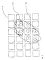
- Fig. 3 presents the observations (An, Bn) measured at the time Tn, and the observations (Am, Bm, ..Gm) measured at the time Tm, in a sensor field comprising sensors (1) of a solution according to one embodiment of the invention.
- the octagons representing the observations of two different moments of time are presented in connection with the sensor at different points for technical drawing reasons.
- the position of the observations of each sensor at different moments of time is of no difference from the viewpoint of the system.
- the system On the basis of the observations of the time Tn and the tracking of the object preceding this, the system has information about the object, of which the location, shape and size are presented as an outline (301).
- the system updates the information of the object as a result of the processing of the observations of the time Tm.
- Information about the object after updating is presented as an outline (302).
- Information about the object at the time Tm, the change in the information with respect to the information of the time Tn and the length of time that has passed between these times fulfill the event conditions known by the system that are set for a falling event.
- the system produces event information about the falling event on the basis of the processing of the observations of the time Tm.
- the extent of the observations that express the proximity of some body part by their strength that are linked to an object are used as an event condition of a falling event, expressed as the area covered by the observations and as the largest distance between the observations, as a change in the speed of the extent, and as the subsequent permanence of the location and strength.
- Observations, which change at a determined speed from observations corresponding to a vertical attitude to observations corresponding to a fallen person, are interpreted according to the condition as falling.
- Fig. 4 presents the processing of measured sensor observations according to one embodiment of the invention in the case of two meeting objects.
- the figure presents the processing of measured sensor observations in a sensor field comprising sensors (1) at the consecutive moments of time T1, T2 and T3.
- the observations (A1) and (B1) are linked to the first object, according to the information of which the outline is (401), and the second observation (C1) of the same moment of time, which is linked to the second object (405).
- the processing of sensor observations has produced information about the states of motion of the objects, which is presented as arrows (404, 408), on the basis of the previously calculated locations and the state of motion of the observations and the objects of the time T1.
- the system measures the observations (E2) and (F2).
- the system links these observations to the objects using the status information of the objects.
- the system links the observation (E2) to a second object, the outline and location (406) of which according to the status information produced by the processing of the observations at the time T2 is presented in the figure.
- the system links the observations (E2) and (F2) to the first object (401).
- the outline and location (402) according to the information produced by the processing of the observations at the time T2 that are linked to this object are also presented in the figure.
- the system correspondingly processes the observations (G3, H3 and 13) of the time T3, which produces new status information for the objects, the outlines according to which for the first (403) and the second (407) object are presented in the figure.
- the result of the processing of the observations of the time T2 and T3 and more particularly the status information of the objects contained in these results correspond with a good degree of accuracy to the movement of the actual objects, because the system has used the earlier status information of the objects in tracking the objects and in updating the status information of the objects.
- the evaluation of the fulfillment of the event conditions made by the system avoids the production of incorrect information e.g. on the basis of the observations of the time T3.
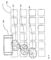
- Fig. 5 presents an observation (502) measured with the sensor field (500) comprising sensors (1) according to one embodiment of the invention, the location of which observation is next to a bed (501) disposed in a space monitored with the sensor field.
- the system processes the sensor observations and links the observation (502) to a new object using information about the relative locations of the bed (501) and the observation (502), as well as information about the fact that the appearance of a new object in the vicinity of the bed (501) is possible. Further the system immediately produces event information on the basis of the observation (502) based on the event condition set for the system, according to which event condition immediate event information about an object appearing in the vicinity of the bed (501) must be produced.
- the appearance conditions of different types of objects are used for detecting the appearance of new objects.
- the appearance conditions guide the operation of the system by setting sensor observations for each object type that interpret that an object has appeared.
- the appearance conditions are compiled such that on the basis of them the system links as few sensor observations as possible to a new object that has appeared, and such that this is not done other than when the probability is sufficiently great that the observations are of the type caused by a new object that has appeared.
- the alternative object types in question are recorded in the information of the object, and on the basis of observations later linked to the object, when this is justified according to the observations, the object types deemed to be less probable for the object are excluded.
- the sensor observations linked to an object are used in detecting the properties of the object.
- the characteristics observed and recorded in the status information of an object can be the extent, shape, height, composition, distribution of mass, ability to move, distribution probability or some other characteristic of the object that is projected to the sensor field, about which there is a need to obtain information.
- the system processes sensor observations such that some characteristic or some characteristics of the object are determined on the basis of the correlation between the observations linked to an object known by the system and the characteristic, and on the basis of the observation series formed by the observations.
- the system can process sensor observations such that a correlation model used in detecting the characteristics is formed on the basis of the observation material and the basis of the known characteristics of the objects that caused the observations.
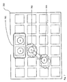
- Fig. 6 presents the observation D1 measured at the time T1, the observations (B2, C2) measured at the time T2, and the observation (A3) measured at the time T3 with a sensor field (500) comprising sensors (1) according to one embodiment of the invention.
- the system according to this embodiment has, on the basis of the observations of the time T1 and on the basis of earlier tracking, updated the status information of the object to be tracked, which is presented in the figure as an outline (601).
- the system has updated the status information of the object to be tracked according to the processing of the observations of the times T2 and T3, which information is presented in the figure as the outlines (602) and (603).
- the information relating to the bed (501), which is described in connection with Fig. 5 is set in the system.
- the system affirms that the event condition applying to getting out of bed is not fulfilled, because the object arrives in the proximity of the bed from elsewhere in the space to be monitored.
- Fig. 7 presents the observations A71 and B71 measured at the time T71, the observation (C72) measured at the time T72, and the observation (D73) measured at the time T73 with a sensor field comprising sensors according to one embodiment of the invention, as well as a structure (700) that delimits the space and an arrival area (701) located in connection with the passage aperture leading to the space.
- the system processes the observations made at the time T71, and records that a new object has appeared in the arrival area. After this the processing of the observation (C72) made at the time T2 links this observation to the new object, the status information of which the system produces using the information applying to the observations (A71, B71 and C72) and the arrival area (701).
- the figure presents an outline (702) according to the status information of these. After the processing of the observation (D73) of the time T3, the outline according to the status information of the aforementioned new object is in a new location (703).
- Fig. 8 presents a space to be monitored with a sensor field comprising sensors according to one embodiment of the invention and the delimitation (700) of the space and the exit area (801) located in connection with the passage opening leading to the space.
- the system according to this embodiment has processed the observation (D1) made at the time T1 and the observation (C2) made at the time T2 and has correspondingly updated the status information of the object being tracked, the outlines (802 and 803) according to which and according to the same times are presented in the figure.
- the status information, after the processing of the observations (A3, B3) of the time T3, of the object to be tracked is presented as an outline (804) in the figure. After this no observation is received that could linked to the same object.
- the system inferred that the object that was in the location (802) has moved via the locations (803) and (804) out of the monitored space.
- the system uses information about changes in the status information of the object, about the exit area (801) and about valid event conditions, and according to the event conditions produces event information applying to an object the has exited the delimited space (700).
- the event condition used by the system is of the type that the event information is produced without delay, on the basis of which the system produces event information about an object to which sensor observations are no longer linked.
- conditions that contain information about the characteristics of the space to be monitored, such as about a route leading away from the space, or about a structure or furniture, from the influence of which the object can stop causing sensor observations after moving from its previous location.
- An example of this type of structure is a stairway leading to the second floor and a high-legged seat is a corresponding example of the furniture.
- conditions when linking observations to the objects that are to be tracked, conditions are used that contain information about the characteristics of the space to be monitored, such as about a route leading away from the space, or about a structure or furniture, after moving into the sphere of influence of which the object stops causing observations and after moving out of the sphere of influence of which the object causes sensor observations.
- the conditions described above are used as a condition of the disappearance and appearance of a new object.
- linking observations to the objects to be tracked conditions that contain information about the area to be delimited to the space to be monitored, to which there is no other route probably used by the objects than the access via the monitored space.
- the delimited area can be a bathroom, a balcony, a cupboard or corresponding.
- information describing the movement of an object deemed to have moved into the delimited area on the basis of the tracking, which is used in linking later sensor observations to the objects, is recorded in the status information.
- Fig. 9 presents the processing of sensor observations according to one preferred embodiment.
- Measurement of the sensor observations (901) produces a sensor observation expressed as a numerical value describing the strength of the observation applying to each sensor of the sensor field at a certain moment of time.
- the observations are linked to objects on the basis of the locations of the sensors of the sensor field, the strength of each observation, the status information of the objects and the time that has passed since the previous observations.
- some sensor observations are linked to the new object if the observations, taking into account information applying to their strength, location and other observations, the objects to be tracked and the space to be monitored, are deemed to be more probably caused by a new object than by an object that is already being tracked.
- the status information of each object being tracked is updated on the basis of the sensor observations linked to it.
- the set event conditions are examined, and event information (905) according to the fulfillment of the event conditions is produced.
Landscapes
- Health & Medical Sciences (AREA)
- Business, Economics & Management (AREA)
- General Physics & Mathematics (AREA)
- Physics & Mathematics (AREA)
- Emergency Management (AREA)
- Gerontology & Geriatric Medicine (AREA)
- General Health & Medical Sciences (AREA)
- Engineering & Computer Science (AREA)
- Human Computer Interaction (AREA)
- Psychiatry (AREA)
- Psychology (AREA)
- Social Psychology (AREA)
- Alarm Systems (AREA)
- Radar Systems Or Details Thereof (AREA)
- Burglar Alarm Systems (AREA)
- Image Analysis (AREA)
Priority Applications (1)
| Application Number | Priority Date | Filing Date | Title |
|---|---|---|---|
| PL09715853T PL2263217T3 (pl) | 2008-02-28 | 2009-02-25 | Sposób i system do wykrywania zdarzeń |
Applications Claiming Priority (3)
| Application Number | Priority Date | Filing Date | Title |
|---|---|---|---|
| FI20080164A FI20080164A0 (fi) | 2008-02-28 | 2008-02-28 | Menetelmä ja järjestelmä tapahtumien havaitsemiseen |
| FI20080236A FI120605B (fi) | 2008-02-28 | 2008-03-26 | Menetelmä ja järjestelmä tapahtumien havaitsemiseen |
| PCT/FI2009/050157 WO2009106685A1 (en) | 2008-02-28 | 2009-02-25 | Method and system for detecting events |
Publications (2)
| Publication Number | Publication Date |
|---|---|
| EP2263217A1 EP2263217A1 (en) | 2010-12-22 |
| EP2263217B1 true EP2263217B1 (en) | 2013-05-22 |
Family
ID=39269472
Family Applications (1)
| Application Number | Title | Priority Date | Filing Date |
|---|---|---|---|
| EP09715853.9A Active EP2263217B1 (en) | 2008-02-28 | 2009-02-25 | Method and system for detecting events |
Country Status (10)
| Country | Link |
|---|---|
| US (1) | US8442800B2 (enExample) |
| EP (1) | EP2263217B1 (enExample) |
| JP (1) | JP5717450B2 (enExample) |
| KR (1) | KR101593713B1 (enExample) |
| DK (1) | DK2263217T3 (enExample) |
| ES (1) | ES2424660T3 (enExample) |
| FI (1) | FI120605B (enExample) |
| PL (1) | PL2263217T3 (enExample) |
| PT (1) | PT2263217E (enExample) |
| WO (1) | WO2009106685A1 (enExample) |
Families Citing this family (27)
| Publication number | Priority date | Publication date | Assignee | Title |
|---|---|---|---|---|
| KR101425605B1 (ko) * | 2008-02-18 | 2014-08-04 | 삼성전자주식회사 | 이벤트 스트럭쳐 시스템 및 그 제어 방법 |
| JP5384319B2 (ja) * | 2009-12-28 | 2014-01-08 | 株式会社ケアコム | 行動検出システム |
| US9301460B2 (en) * | 2011-02-25 | 2016-04-05 | The Toro Company | Irrigation controller with weather station |
| FR2989711B1 (fr) * | 2012-04-19 | 2014-05-09 | Claude Desgorces | Piece de revetement de sol pour la detection de chutes |
| US9262294B2 (en) * | 2011-10-31 | 2016-02-16 | Hewlett Packard Enterprise Development Lp | System and method for event detection and correlation from moving object sensor data |
| FR2996673B1 (fr) * | 2012-10-05 | 2016-02-05 | Bostik Sa | Capteur capacitif pour la detection de presence d'un objet et/ou d'un individu. |
| FI124949B (fi) | 2014-01-03 | 2015-04-15 | Elsi Technologies Oy | Menetelmä ja järjestelmä valvontaan |
| KR101452388B1 (ko) * | 2014-05-22 | 2014-10-27 | 신화건설(주) | 교량 감시 시스템 |
| FI125745B (fi) * | 2014-07-18 | 2016-01-29 | Maricare Oy | Anturijärjestely |
| GB2531316A (en) * | 2014-10-16 | 2016-04-20 | Sanjay Mehalle Puri | A room floor apparatus |
| KR20170093158A (ko) | 2014-11-24 | 2017-08-14 | 타케트 지디엘 에스에이 | 바닥재에 압력 센서를 갖는 모니터링 시스템 |
| CN104616429B (zh) * | 2015-01-07 | 2019-04-26 | 深圳市金立通信设备有限公司 | 一种告警方法 |
| WO2016118797A1 (en) * | 2015-01-22 | 2016-07-28 | Interface, Inc. | Floor covering system with sensors |
| KR101708491B1 (ko) * | 2015-04-03 | 2017-02-20 | 삼성에스디에스 주식회사 | 압력 센서를 이용한 객체 인식 방법 |
| CN104900010B (zh) * | 2015-06-17 | 2017-05-17 | 广东乐源数字技术有限公司 | 一种悬浮隔空触控跌倒报警浴室垫系统 |
| WO2017162810A1 (en) | 2016-03-25 | 2017-09-28 | Tarkett Gdl | In-floor distributed antenna and positioning system |
| LU93111B1 (en) | 2016-06-16 | 2018-01-09 | Tarkett Gdl Sa | Floor-based person monitoring system |
| LU93285B1 (en) | 2016-10-31 | 2018-05-29 | Tarkett Gdl Sa | Behavior monotoring system and method |
| KR102232700B1 (ko) * | 2017-09-14 | 2021-03-26 | (주)엘지하우시스 | 환자 및 노약자의 낙상 감지방법 |
| US20190208018A1 (en) | 2018-01-02 | 2019-07-04 | Scanalytics, Inc. | System and method for smart building control using multidimensional presence sensor arrays |
| DE102018103793B4 (de) * | 2018-02-20 | 2022-03-31 | Ardex Gmbh | Verfahren zum Erfassen eines Ereignisses in einem Raum sowie Flächensensorik |
| US20200110194A1 (en) * | 2018-10-08 | 2020-04-09 | UDP Labs, Inc. | Multidimensional Multivariate Multiple Sensor System |
| CN111134685B (zh) * | 2018-11-02 | 2022-08-09 | 富士通株式会社 | 跌倒检测方法和装置 |
| US12123763B2 (en) | 2019-02-12 | 2024-10-22 | Sleep Number Corporation | Load sensor assembly for bed leg and bed with load sensor assembly |
| KR102357196B1 (ko) * | 2019-09-20 | 2022-01-28 | 한국전자통신연구원 | 보행 분석 장치 및 방법 |
| US20220093277A1 (en) * | 2019-11-26 | 2022-03-24 | Scanalytics, Inc. | Path analytics of disease vectors in a physical space using smart floor tiles |
| US20210158057A1 (en) * | 2019-11-26 | 2021-05-27 | Scanalytics, Inc. | Path analytics of people in a physical space using smart floor tiles |
Family Cites Families (16)
| Publication number | Priority date | Publication date | Assignee | Title |
|---|---|---|---|---|
| US4888581A (en) | 1988-04-06 | 1989-12-19 | Aritech Corporation | Pressure sensitive security system for tracking motion over a surface |
| JP3238113B2 (ja) * | 1997-12-01 | 2001-12-10 | 財団法人新産業創造研究機構 | 健康管理装置 |
| US6515586B1 (en) | 1998-12-18 | 2003-02-04 | Intel Corporation | Tactile tracking systems and methods |
| JP2005528967A (ja) * | 2002-06-06 | 2005-09-29 | インストルメンタリウム コーポレーション | 追跡環境における活動を選択的に監視する方法およびシステム |
| US7617167B2 (en) * | 2003-04-09 | 2009-11-10 | Avisere, Inc. | Machine vision system for enterprise management |
| US6882959B2 (en) * | 2003-05-02 | 2005-04-19 | Microsoft Corporation | System and process for tracking an object state using a particle filter sensor fusion technique |
| US20050052533A1 (en) * | 2003-09-05 | 2005-03-10 | Hitachi Kokusai Electric Inc. | Object tracking method and object tracking apparatus |
| DE102004018813A1 (de) * | 2004-04-19 | 2006-02-23 | Ibeo Automobile Sensor Gmbh | Verfahren zur Erkennung und/oder Verfolgung von Objekten |
| JP4059446B2 (ja) * | 2004-05-21 | 2008-03-12 | 日本電信電話株式会社 | 足跡情報を用いたコミュニケーションシステムおよびコミュニケーション方法 |
| ES2635268T3 (es) * | 2004-05-28 | 2017-10-03 | Saab Ab | Seguimiento de un objeto en movimiento para un sistema de autodefensa |
| DE102004038494A1 (de) * | 2004-08-07 | 2006-03-16 | Robert Bosch Gmbh | Verfahren und Vorrichtung zum Betreiben eines Sensorsystems |
| US7382267B2 (en) * | 2005-01-31 | 2008-06-03 | Artis Llc | Systems and methods for area activity monitoring and personnel identification |
| KR100772500B1 (ko) * | 2005-06-03 | 2007-11-01 | 한국전자통신연구원 | 전파 식별 감지부 및 이를 이용한 물체 위치 추적 장치 및방법 |
| US7944468B2 (en) * | 2005-07-05 | 2011-05-17 | Northrop Grumman Systems Corporation | Automated asymmetric threat detection using backward tracking and behavioral analysis |
| EP1923756B1 (en) * | 2006-11-07 | 2009-04-29 | BrainLAB AG | Method and system for region of interest calibration parameter adjustment of tracking systems |
| US8401304B2 (en) * | 2007-07-27 | 2013-03-19 | Sportvision, Inc. | Detecting an object in an image using edge detection and morphological processing |
-
2008
- 2008-03-26 FI FI20080236A patent/FI120605B/fi active IP Right Grant
-
2009
- 2009-02-25 US US12/919,911 patent/US8442800B2/en not_active Expired - Fee Related
- 2009-02-25 EP EP09715853.9A patent/EP2263217B1/en active Active
- 2009-02-25 KR KR1020107021496A patent/KR101593713B1/ko not_active Expired - Fee Related
- 2009-02-25 ES ES09715853T patent/ES2424660T3/es active Active
- 2009-02-25 DK DK09715853.9T patent/DK2263217T3/da active
- 2009-02-25 PT PT97158539T patent/PT2263217E/pt unknown
- 2009-02-25 PL PL09715853T patent/PL2263217T3/pl unknown
- 2009-02-25 WO PCT/FI2009/050157 patent/WO2009106685A1/en not_active Ceased
- 2009-02-25 JP JP2010548135A patent/JP5717450B2/ja active Active
Also Published As
| Publication number | Publication date |
|---|---|
| DK2263217T3 (da) | 2013-08-26 |
| WO2009106685A1 (en) | 2009-09-03 |
| FI20080236A0 (fi) | 2008-03-26 |
| KR101593713B1 (ko) | 2016-02-12 |
| US20110004435A1 (en) | 2011-01-06 |
| ES2424660T3 (es) | 2013-10-07 |
| PL2263217T3 (pl) | 2013-10-31 |
| PT2263217E (pt) | 2013-08-23 |
| FI20080236L (fi) | 2009-08-29 |
| EP2263217A1 (en) | 2010-12-22 |
| US8442800B2 (en) | 2013-05-14 |
| JP2011517353A (ja) | 2011-06-02 |
| FI120605B (fi) | 2009-12-15 |
| JP5717450B2 (ja) | 2015-05-13 |
| KR20110033102A (ko) | 2011-03-30 |
Similar Documents
| Publication | Publication Date | Title |
|---|---|---|
| EP2263217B1 (en) | Method and system for detecting events | |
| RU2519467C2 (ru) | Система и способ для обнаружения экранирования маркера электронной системы наблюдения за перемещением предметов | |
| US20020104013A1 (en) | Electronic vehicle product and personal monitoring | |
| EP3568839B1 (en) | Optical system for monitoring the movement of people through a passageway | |
| KR20140043430A (ko) | 관측을 위한 방법 및 시스템 | |
| JPH02169481A (ja) | 携帯式エレベータ交通パターンモニター装置 | |
| CN114140997B (zh) | 养老院卫生间老人滞留及身体状况监测预警系统及方法 | |
| US20240077603A1 (en) | Sensor and system for monitoring | |
| CN110581980B (zh) | 安全监控系统的运作方式 | |
| KR20190006824A (ko) | 스마트 태그 모니터링 시스템 및 그 방법 | |
| CN119479179B (zh) | 一种高可靠性火灾探测方法和系统 | |
| EP3803820B1 (en) | Tracking individual user health using intrusion detection sensors | |
| EP3617933A1 (en) | Detecting room occupancy with binary pir sensors | |
| KR20250061728A (ko) | 사람을 모니터링하기 위한 센서 배열 및 시스템 | |
| WO2025199710A1 (en) | Data processing method and related apparatuses | |
| Samuel et al. | Evaluation of millimeter wave radar-based smart home monitoring systems in health care applications for elderly people. | |
| FI20215056A1 (en) | Sensor and system for monitoring | |
| WO2025012435A1 (en) | System and method for operating an automatic door system using a radar sensor | |
| HK40029098B (en) | Method and device for determining a mapping of a number of floors to be served by an elevator and for determining relative trip-dependent data of an elevator cabin |
Legal Events
| Date | Code | Title | Description |
|---|---|---|---|
| PUAI | Public reference made under article 153(3) epc to a published international application that has entered the european phase |
Free format text: ORIGINAL CODE: 0009012 |
|
| 17P | Request for examination filed |
Effective date: 20100928 |
|
| AK | Designated contracting states |
Kind code of ref document: A1 Designated state(s): AT BE BG CH CY CZ DE DK EE ES FI FR GB GR HR HU IE IS IT LI LT LU LV MC MK MT NL NO PL PT RO SE SI SK TR |
|
| AX | Request for extension of the european patent |
Extension state: AL BA RS |
|
| DAX | Request for extension of the european patent (deleted) | ||
| 17Q | First examination report despatched |
Effective date: 20111110 |
|
| REG | Reference to a national code |
Ref country code: DE Ref legal event code: R079 Ref document number: 602009015875 Country of ref document: DE Free format text: PREVIOUS MAIN CLASS: G08B0013100000 Ipc: G08B0021040000 |
|
| GRAP | Despatch of communication of intention to grant a patent |
Free format text: ORIGINAL CODE: EPIDOSNIGR1 |
|
| RIC1 | Information provided on ipc code assigned before grant |
Ipc: G08B 21/04 20060101AFI20121130BHEP Ipc: G08B 13/10 20060101ALN20121130BHEP |
|
| GRAS | Grant fee paid |
Free format text: ORIGINAL CODE: EPIDOSNIGR3 |
|
| GRAA | (expected) grant |
Free format text: ORIGINAL CODE: 0009210 |
|
| AK | Designated contracting states |
Kind code of ref document: B1 Designated state(s): AT BE BG CH CY CZ DE DK EE ES FI FR GB GR HR HU IE IS IT LI LT LU LV MC MK MT NL NO PL PT RO SE SI SK TR |
|
| REG | Reference to a national code |
Ref country code: GB Ref legal event code: FG4D |
|
| REG | Reference to a national code |
Ref country code: CH Ref legal event code: EP |
|
| REG | Reference to a national code |
Ref country code: AT Ref legal event code: REF Ref document number: 613580 Country of ref document: AT Kind code of ref document: T Effective date: 20130615 |
|
| REG | Reference to a national code |
Ref country code: IE Ref legal event code: FG4D |
|
| REG | Reference to a national code |
Ref country code: DE Ref legal event code: R096 Ref document number: 602009015875 Country of ref document: DE Effective date: 20130718 |
|
| RAP2 | Party data changed (patent owner data changed or rights of a patent transferred) |
Owner name: PROFITE OY |
|
| RAP2 | Party data changed (patent owner data changed or rights of a patent transferred) |
Owner name: ELSI TECHNOLOGIES OY |
|
| REG | Reference to a national code |
Ref country code: SE Ref legal event code: TRGR |
|
| REG | Reference to a national code |
Ref country code: PT Ref legal event code: SC4A Free format text: AVAILABILITY OF NATIONAL TRANSLATION Effective date: 20130807 |
|
| REG | Reference to a national code |
Ref country code: DK Ref legal event code: T3 |
|
| REG | Reference to a national code |
Ref country code: CH Ref legal event code: NV Representative=s name: ARNOLD AND SIEDSMA AG, CH |
|
| REG | Reference to a national code |
Ref country code: NL Ref legal event code: T3 |
|
| REG | Reference to a national code |
Ref country code: NO Ref legal event code: T2 Effective date: 20130522 Ref country code: ES Ref legal event code: FG2A Ref document number: 2424660 Country of ref document: ES Kind code of ref document: T3 Effective date: 20131007 |
|
| REG | Reference to a national code |
Ref country code: DE Ref legal event code: R082 Ref document number: 602009015875 Country of ref document: DE Representative=s name: RUEGER, BARTHELT & ABEL PATENTANWAELTE, DE |
|
| REG | Reference to a national code |
Ref country code: GR Ref legal event code: EP Ref document number: 20130401732 Country of ref document: GR Effective date: 20130920 |
|
| REG | Reference to a national code |
Ref country code: LT Ref legal event code: MG4D |
|
| PG25 | Lapsed in a contracting state [announced via postgrant information from national office to epo] |
Ref country code: IS Free format text: LAPSE BECAUSE OF FAILURE TO SUBMIT A TRANSLATION OF THE DESCRIPTION OR TO PAY THE FEE WITHIN THE PRESCRIBED TIME-LIMIT Effective date: 20130922 Ref country code: SI Free format text: LAPSE BECAUSE OF FAILURE TO SUBMIT A TRANSLATION OF THE DESCRIPTION OR TO PAY THE FEE WITHIN THE PRESCRIBED TIME-LIMIT Effective date: 20130522 Ref country code: LT Free format text: LAPSE BECAUSE OF FAILURE TO SUBMIT A TRANSLATION OF THE DESCRIPTION OR TO PAY THE FEE WITHIN THE PRESCRIBED TIME-LIMIT Effective date: 20130522 |
|
| REG | Reference to a national code |
Ref country code: PL Ref legal event code: T3 |
|
| PG25 | Lapsed in a contracting state [announced via postgrant information from national office to epo] |
Ref country code: BG Free format text: LAPSE BECAUSE OF FAILURE TO SUBMIT A TRANSLATION OF THE DESCRIPTION OR TO PAY THE FEE WITHIN THE PRESCRIBED TIME-LIMIT Effective date: 20130822 Ref country code: HR Free format text: LAPSE BECAUSE OF FAILURE TO SUBMIT A TRANSLATION OF THE DESCRIPTION OR TO PAY THE FEE WITHIN THE PRESCRIBED TIME-LIMIT Effective date: 20130522 |
|
| REG | Reference to a national code |
Ref country code: DE Ref legal event code: R082 Ref document number: 602009015875 Country of ref document: DE Representative=s name: RUEGER | ABEL PATENT- UND RECHTSANWAELTE, DE Effective date: 20131014 Ref country code: DE Ref legal event code: R082 Ref document number: 602009015875 Country of ref document: DE Representative=s name: RUEGER ABEL PATENT- UND RECHTSANWAELTE, DE Effective date: 20131014 Ref country code: DE Ref legal event code: R082 Ref document number: 602009015875 Country of ref document: DE Representative=s name: RUEGER, BARTHELT & ABEL PATENTANWAELTE, DE Effective date: 20131014 Ref country code: DE Ref legal event code: R081 Ref document number: 602009015875 Country of ref document: DE Owner name: ELSI TECHNOLOGIES OY, FI Free format text: FORMER OWNER: MARIMILS OY, VANTAA, FI Effective date: 20131014 |
|
| PG25 | Lapsed in a contracting state [announced via postgrant information from national office to epo] |
Ref country code: LV Free format text: LAPSE BECAUSE OF FAILURE TO SUBMIT A TRANSLATION OF THE DESCRIPTION OR TO PAY THE FEE WITHIN THE PRESCRIBED TIME-LIMIT Effective date: 20130522 |
|
| PG25 | Lapsed in a contracting state [announced via postgrant information from national office to epo] |
Ref country code: SK Free format text: LAPSE BECAUSE OF FAILURE TO SUBMIT A TRANSLATION OF THE DESCRIPTION OR TO PAY THE FEE WITHIN THE PRESCRIBED TIME-LIMIT Effective date: 20130522 Ref country code: EE Free format text: LAPSE BECAUSE OF FAILURE TO SUBMIT A TRANSLATION OF THE DESCRIPTION OR TO PAY THE FEE WITHIN THE PRESCRIBED TIME-LIMIT Effective date: 20130522 Ref country code: CZ Free format text: LAPSE BECAUSE OF FAILURE TO SUBMIT A TRANSLATION OF THE DESCRIPTION OR TO PAY THE FEE WITHIN THE PRESCRIBED TIME-LIMIT Effective date: 20130522 |
|
| PG25 | Lapsed in a contracting state [announced via postgrant information from national office to epo] |
Ref country code: RO Free format text: LAPSE BECAUSE OF FAILURE TO SUBMIT A TRANSLATION OF THE DESCRIPTION OR TO PAY THE FEE WITHIN THE PRESCRIBED TIME-LIMIT Effective date: 20130522 |
|
| PLBE | No opposition filed within time limit |
Free format text: ORIGINAL CODE: 0009261 |
|
| STAA | Information on the status of an ep patent application or granted ep patent |
Free format text: STATUS: NO OPPOSITION FILED WITHIN TIME LIMIT |
|
| 26N | No opposition filed |
Effective date: 20140225 |
|
| REG | Reference to a national code |
Ref country code: DE Ref legal event code: R097 Ref document number: 602009015875 Country of ref document: DE Effective date: 20140225 |
|
| PG25 | Lapsed in a contracting state [announced via postgrant information from national office to epo] |
Ref country code: MC Free format text: LAPSE BECAUSE OF FAILURE TO SUBMIT A TRANSLATION OF THE DESCRIPTION OR TO PAY THE FEE WITHIN THE PRESCRIBED TIME-LIMIT Effective date: 20130522 Ref country code: LU Free format text: LAPSE BECAUSE OF FAILURE TO SUBMIT A TRANSLATION OF THE DESCRIPTION OR TO PAY THE FEE WITHIN THE PRESCRIBED TIME-LIMIT Effective date: 20140225 |
|
| REG | Reference to a national code |
Ref country code: FR Ref legal event code: PLFP Year of fee payment: 8 |
|
| PG25 | Lapsed in a contracting state [announced via postgrant information from national office to epo] |
Ref country code: MT Free format text: LAPSE BECAUSE OF FAILURE TO SUBMIT A TRANSLATION OF THE DESCRIPTION OR TO PAY THE FEE WITHIN THE PRESCRIBED TIME-LIMIT Effective date: 20130522 |
|
| PG25 | Lapsed in a contracting state [announced via postgrant information from national office to epo] |
Ref country code: CY Free format text: LAPSE BECAUSE OF FAILURE TO SUBMIT A TRANSLATION OF THE DESCRIPTION OR TO PAY THE FEE WITHIN THE PRESCRIBED TIME-LIMIT Effective date: 20130522 |
|
| PG25 | Lapsed in a contracting state [announced via postgrant information from national office to epo] |
Ref country code: HU Free format text: LAPSE BECAUSE OF FAILURE TO SUBMIT A TRANSLATION OF THE DESCRIPTION OR TO PAY THE FEE WITHIN THE PRESCRIBED TIME-LIMIT; INVALID AB INITIO Effective date: 20090225 |
|
| REG | Reference to a national code |
Ref country code: FR Ref legal event code: PLFP Year of fee payment: 9 |
|
| REG | Reference to a national code |
Ref country code: FR Ref legal event code: PLFP Year of fee payment: 10 |
|
| PG25 | Lapsed in a contracting state [announced via postgrant information from national office to epo] |
Ref country code: MK Free format text: LAPSE BECAUSE OF FAILURE TO SUBMIT A TRANSLATION OF THE DESCRIPTION OR TO PAY THE FEE WITHIN THE PRESCRIBED TIME-LIMIT Effective date: 20130522 |
|
| PGFP | Annual fee paid to national office [announced via postgrant information from national office to epo] |
Ref country code: NL Payment date: 20200219 Year of fee payment: 12 Ref country code: IT Payment date: 20200225 Year of fee payment: 12 Ref country code: DK Payment date: 20200224 Year of fee payment: 12 Ref country code: PL Payment date: 20200130 Year of fee payment: 12 Ref country code: PT Payment date: 20200220 Year of fee payment: 12 Ref country code: NO Payment date: 20200224 Year of fee payment: 12 Ref country code: ES Payment date: 20200322 Year of fee payment: 12 Ref country code: IE Payment date: 20200219 Year of fee payment: 12 Ref country code: SE Payment date: 20200220 Year of fee payment: 12 Ref country code: GR Payment date: 20200220 Year of fee payment: 12 Ref country code: AT Payment date: 20200220 Year of fee payment: 12 |
|
| PGFP | Annual fee paid to national office [announced via postgrant information from national office to epo] |
Ref country code: BE Payment date: 20200219 Year of fee payment: 12 Ref country code: CH Payment date: 20200219 Year of fee payment: 12 |
|
| PGFP | Annual fee paid to national office [announced via postgrant information from national office to epo] |
Ref country code: TR Payment date: 20200224 Year of fee payment: 12 |
|
| REG | Reference to a national code |
Ref country code: DK Ref legal event code: EBP Effective date: 20210228 |
|
| REG | Reference to a national code |
Ref country code: NO Ref legal event code: MMEP |
|
| REG | Reference to a national code |
Ref country code: SE Ref legal event code: EUG |
|
| REG | Reference to a national code |
Ref country code: AT Ref legal event code: MM01 Ref document number: 613580 Country of ref document: AT Kind code of ref document: T Effective date: 20210225 |
|
| REG | Reference to a national code |
Ref country code: BE Ref legal event code: MM Effective date: 20210228 |
|
| PG25 | Lapsed in a contracting state [announced via postgrant information from national office to epo] |
Ref country code: AT Free format text: LAPSE BECAUSE OF NON-PAYMENT OF DUE FEES Effective date: 20210225 Ref country code: CH Free format text: LAPSE BECAUSE OF NON-PAYMENT OF DUE FEES Effective date: 20210228 Ref country code: LI Free format text: LAPSE BECAUSE OF NON-PAYMENT OF DUE FEES Effective date: 20210228 |
|
| PG25 | Lapsed in a contracting state [announced via postgrant information from national office to epo] |
Ref country code: GR Free format text: LAPSE BECAUSE OF NON-PAYMENT OF DUE FEES Effective date: 20210906 Ref country code: SE Free format text: LAPSE BECAUSE OF NON-PAYMENT OF DUE FEES Effective date: 20210226 Ref country code: PT Free format text: LAPSE BECAUSE OF NON-PAYMENT OF DUE FEES Effective date: 20210825 Ref country code: NO Free format text: LAPSE BECAUSE OF NON-PAYMENT OF DUE FEES Effective date: 20210228 |
|
| REG | Reference to a national code |
Ref country code: NL Ref legal event code: MM Effective date: 20210301 |
|
| PG25 | Lapsed in a contracting state [announced via postgrant information from national office to epo] |
Ref country code: NL Free format text: LAPSE BECAUSE OF NON-PAYMENT OF DUE FEES Effective date: 20210301 |
|
| PG25 | Lapsed in a contracting state [announced via postgrant information from national office to epo] |
Ref country code: DK Free format text: LAPSE BECAUSE OF NON-PAYMENT OF DUE FEES Effective date: 20210228 Ref country code: IE Free format text: LAPSE BECAUSE OF NON-PAYMENT OF DUE FEES Effective date: 20210225 |
|
| PG25 | Lapsed in a contracting state [announced via postgrant information from national office to epo] |
Ref country code: IT Free format text: LAPSE BECAUSE OF NON-PAYMENT OF DUE FEES Effective date: 20210225 |
|
| REG | Reference to a national code |
Ref country code: ES Ref legal event code: FD2A Effective date: 20220513 |
|
| PG25 | Lapsed in a contracting state [announced via postgrant information from national office to epo] |
Ref country code: ES Free format text: LAPSE BECAUSE OF NON-PAYMENT OF DUE FEES Effective date: 20210226 Ref country code: BE Free format text: LAPSE BECAUSE OF NON-PAYMENT OF DUE FEES Effective date: 20210228 |
|
| PGFP | Annual fee paid to national office [announced via postgrant information from national office to epo] |
Ref country code: FR Payment date: 20230221 Year of fee payment: 15 Ref country code: FI Payment date: 20230224 Year of fee payment: 15 |
|
| PG25 | Lapsed in a contracting state [announced via postgrant information from national office to epo] |
Ref country code: PL Free format text: LAPSE BECAUSE OF NON-PAYMENT OF DUE FEES Effective date: 20210225 |
|
| PGFP | Annual fee paid to national office [announced via postgrant information from national office to epo] |
Ref country code: GB Payment date: 20230220 Year of fee payment: 15 Ref country code: DE Payment date: 20230216 Year of fee payment: 15 |
|
| P01 | Opt-out of the competence of the unified patent court (upc) registered |
Effective date: 20230614 |
|
| REG | Reference to a national code |
Ref country code: DE Ref legal event code: R119 Ref document number: 602009015875 Country of ref document: DE |
|
| PG25 | Lapsed in a contracting state [announced via postgrant information from national office to epo] |
Ref country code: FI Free format text: LAPSE BECAUSE OF NON-PAYMENT OF DUE FEES Effective date: 20240225 |
|
| GBPC | Gb: european patent ceased through non-payment of renewal fee |
Effective date: 20240225 |
|
| PG25 | Lapsed in a contracting state [announced via postgrant information from national office to epo] |
Ref country code: FI Free format text: LAPSE BECAUSE OF NON-PAYMENT OF DUE FEES Effective date: 20240225 |
|
| PG25 | Lapsed in a contracting state [announced via postgrant information from national office to epo] |
Ref country code: DE Free format text: LAPSE BECAUSE OF NON-PAYMENT OF DUE FEES Effective date: 20240903 |
|
| PG25 | Lapsed in a contracting state [announced via postgrant information from national office to epo] |
Ref country code: GB Free format text: LAPSE BECAUSE OF NON-PAYMENT OF DUE FEES Effective date: 20240225 |
|
| PG25 | Lapsed in a contracting state [announced via postgrant information from national office to epo] |
Ref country code: FR Free format text: LAPSE BECAUSE OF NON-PAYMENT OF DUE FEES Effective date: 20240229 |
|
| PG25 | Lapsed in a contracting state [announced via postgrant information from national office to epo] |
Ref country code: GB Free format text: LAPSE BECAUSE OF NON-PAYMENT OF DUE FEES Effective date: 20240225 Ref country code: FR Free format text: LAPSE BECAUSE OF NON-PAYMENT OF DUE FEES Effective date: 20240229 Ref country code: DE Free format text: LAPSE BECAUSE OF NON-PAYMENT OF DUE FEES Effective date: 20240903 |