EP2263155B1 - Direkte datenübertragung zwischen nebengeräten - Google Patents
Direkte datenübertragung zwischen nebengeräten Download PDFInfo
- Publication number
- EP2263155B1 EP2263155B1 EP09730967A EP09730967A EP2263155B1 EP 2263155 B1 EP2263155 B1 EP 2263155B1 EP 09730967 A EP09730967 A EP 09730967A EP 09730967 A EP09730967 A EP 09730967A EP 2263155 B1 EP2263155 B1 EP 2263155B1
- Authority
- EP
- European Patent Office
- Prior art keywords
- data
- devices
- slave
- bus
- communication lines
- Prior art date
- Legal status (The legal status is an assumption and is not a legal conclusion. Google has not performed a legal analysis and makes no representation as to the accuracy of the status listed.)
- Not-in-force
Links
Images

Classifications
-
- G—PHYSICS
- G06—COMPUTING OR CALCULATING; COUNTING
- G06F—ELECTRIC DIGITAL DATA PROCESSING
- G06F13/00—Interconnection of, or transfer of information or other signals between, memories, input/output devices or central processing units
- G06F13/14—Handling requests for interconnection or transfer
- G06F13/20—Handling requests for interconnection or transfer for access to input/output bus
- G06F13/28—Handling requests for interconnection or transfer for access to input/output bus using burst mode transfer, e.g. direct memory access DMA, cycle steal
-
- G—PHYSICS
- G06—COMPUTING OR CALCULATING; COUNTING
- G06F—ELECTRIC DIGITAL DATA PROCESSING
- G06F13/00—Interconnection of, or transfer of information or other signals between, memories, input/output devices or central processing units
- G06F13/14—Handling requests for interconnection or transfer
- G06F13/16—Handling requests for interconnection or transfer for access to memory bus
- G06F13/1668—Details of memory controller
- G06F13/1684—Details of memory controller using multiple buses
-
- G—PHYSICS
- G06—COMPUTING OR CALCULATING; COUNTING
- G06F—ELECTRIC DIGITAL DATA PROCESSING
- G06F13/00—Interconnection of, or transfer of information or other signals between, memories, input/output devices or central processing units
- G06F13/14—Handling requests for interconnection or transfer
- G06F13/36—Handling requests for interconnection or transfer for access to common bus or bus system
- G06F13/368—Handling requests for interconnection or transfer for access to common bus or bus system with decentralised access control
- G06F13/37—Handling requests for interconnection or transfer for access to common bus or bus system with decentralised access control using a physical-position-dependent priority, e.g. daisy chain, round robin or token passing
-
- H—ELECTRICITY
- H04—ELECTRIC COMMUNICATION TECHNIQUE
- H04L—TRANSMISSION OF DIGITAL INFORMATION, e.g. TELEGRAPHIC COMMUNICATION
- H04L12/00—Data switching networks
- H04L12/28—Data switching networks characterised by path configuration, e.g. LAN [Local Area Networks] or WAN [Wide Area Networks]
- H04L12/40—Bus networks
- H04L12/40006—Architecture of a communication node
Definitions
- the present invention relates generally to transferring data over communication lines between passive slave devices. More particularly, the invention relates to host device initiated data transferring between passive slave devices without first transferring the data to the host device or any other intermediary storage device.
- bus It has become commonplace to connect a host processor to different devices using a plurality of conducting wires referred to as a "bus" that typically complies with well known standards.
- the devices connected to the bus may include memory / storage devices, communications devices, sensing devices, etc. and these devices may be either fixed or removable.
- some or all of the wires that define the bus are shared amongst any and/or all of the devices that are connected to the bus. Since the devices coupled to the bus share the same conducting wires, each device is typically assigned a unique ID or address on the bus and is configured to respond only to messages that are addressed to that unique ID / address. In this way, multiple devices can share the same conducting wires that form the bus resulting in a substantially reduced bus size than would otherwise be required.
- Master/slave is a model for a communication protocol in which one device or process has unidirectional control over one or more other devices.
- the direction of control is always from the master to the slaves, i.e. a slave cannot initiate a transaction.
- a master is elected from a group of eligible devices with the other devices acting in the role of slaves.
- data is not transferred directly between slave devices; rather, data is typically passed over the common bus from a source slave storage device to a host controller or other intermediary where the data is temporarily cached before being re-output by the host controller over the common bus and targeted towards a destination slave storage device where the data is then read from the bus and stored.
- a method of directly transferring data between a first and a second device coupled with each other and with a master device with one or more communication lines is described.
- the master device instructs the first device to listen to the one or more communication lines.
- the second device transmits data onto the one or more communication lines. In this way, the data transmitted onto the one or more communication lines by the second device is received by the first device without further intervention by the master device.
- a method of transferring data over a plurality of communication lines is described.
- a first command is sent from a master device coupled with the communication lines to a first destination slave device coupled with the communication lines.
- the first command instructs the first destination slave device to listen to and write data from the communication lines starting at a first time.
- a second command is also sent from the master device to a second source slave device coupled with the communication lines.
- the second command instructs the second source slave device to read and output first data onto the communication lines starting at or after the first time.
- the first data output from the second source slave device beginning at the first time is stored by the first destination slave device beginning at the first time without requiring first transferring the first data to the master device or any other temporary storage device.
- a method of communicating over a plurality of communication lines is described.
- a first command is sent from a master device coupled with the communication lines to a first slave device coupled with the communication lines.
- the first command instructs the first destination slave device to listen to the communication lines starting at a first time.
- a second command is also sent from the master device to a second slave device coupled with the communication lines.
- the second command instructs the second slave device to output a third communication onto the communication lines starting at or after the first time. In this way, the third communication output from the second slave device beginning at the first time is read by the first slave device beginning at the first time without requiring first transferring the third communication to the master device or any other device.
- a system for implementing each of the aforementioned methods.
- a system includes a first addressable destination slave device configured to store data, a second addressable source slave device configured to store data and including first data stored therein, and a master device arranged to manage the first and second slave devices.
- the system further includes a plurality of communication lines that couple the master device and at least each of the first and second slave devices.
- the master device is further arranged to send a first command to the first slave device instructing the first slave device to listen to and write data from the communication lines beginning at a first time and a second command to the second slave device instructing the second slave device to read and output the first data onto the communication lines beginning at or after the first time, such that the first data is transferred from the second source slave device to the first destination slave device without requiring first transferring the first data to the master device or any other storage device.
- the system includes a first addressable slave device, a second addressable slave device, a master device arranged to manage the first and second slave devices, and a plurality of communication lines that couple the master device and at least each of the first and second slave devices.
- the master device is further arranged to send a first command to the first slave device instructing the first slave device to listen to the communication lines beginning at a first time and a second command to the second slave device instructing the second slave device to output a third communication onto the communication lines beginning at or after the first time, wherein the third communication output from the second slave device beginning at the first time is read by the first slave device beginning at the first time without requiring first transferring the third communication to the master device or any other device.
- Figure 1 illustrates a simplified block diagram of a system in accordance with an embodiment of the present invention.
- Figure 2 illustrates s simplified block diagram of an example storage device in accordance with an embodiment of the present invention.
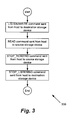
- Figure 3 shows a flowchart illustrating a process of transferring data directly between storage devices.
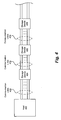
- Figure 4 illustrates a simplified block diagram of a system including a plurality of storage devices arranged into a daisy chain configuration in accordance with an embodiment of the present invention.
- aspects of the present invention describe methods, devices and systems for transferring data over communication lines that couple two or more slave devices with a master device, and in particular embodiments, two or more storage devices with a host device. Particular embodiments of the invention are discussed below with reference to Figures 1 through 4 .
- the following description focuses on embodiments in which the storage devices are interconnected via a memory/storage related bus to a host device serving as a master device and in which data is transferred directly from one storage device to another without first transferring the data to the host device or any other intermediate device, and in which the slave storage devices are incapable of initiating the transfer between themselves.
- the storage devices are not interconnected with a conventional bus architecture; rather, each device is connected only with its neighboring devices.
- the storage devices are presumed to be non-volatile storage devices.
- the invention may also be implemented on volatile storage devices.
- the non-volatile storage devices may be FLASH or EEPROM based storage devices.
- the storage devices may also be either removable or non-removable (fixed) devices. As is well known, non-removable devices are not intended for subsequent removal from the bus once they have been connected with the bus whereas removable devices are configured so as to be readily removed or added to the bus.
- One type of removable device that is well suited for use as a storage device according to the present invention is a memory card.
- Memory cards are commonly used to store digital data for use with various electronics products.
- the memory card is often removable from the host system so the stored digital data is portable.
- the memory cards can have a relatively small form factor and be used to store digital data for various electronics products and systems including personal computers, notebook computers, hand-held computing devices, cameras, cellular telephones, media players/recorders (e.g., MP3 devices), personal digital assistants (PDAs), network cards, network appliances, set-top boxes, and other hand-held or embedded devices.
- the storage device configuration does not depend on the type of removable memory, and may be implemented with any type of memory, whether it being a flash memory or another type of memory.
- the storage device may also be implemented with a one-time programmable (OTP) memory chip and/or with a 3 dimensional memory chip technology.
- OTP one-time programmable
- FIG. 1 illustrates a simplified block diagram of a master/slave system 100 in accordance with an embodiment of the present invention.
- a slave device may take the form of a local storage device such as but not limited to any of the aforementioned storage devices described above while the master device takes the form of a host device such as but not limited to any of the aforementioned host devices described above.
- master/slave is a model for a communication protocol in which one device or process has unidirectional control over one or more other devices. In a conventional system, once a master/slave relationship between devices or processes is established, the direction of control is always from the master to the slaves, i.e. a slave cannot initiate a transaction.
- master/slave system 100 (hereinafter also referred to simply as system 100) includes at least master device 102 (hereinafter also referred to as host device 102 or host controller 102), first slave device 104 (hereinafter also referred to as storage device 104) and second slave device 106 (hereinafter also referred to as storage device 106) that relate to each other at least by way of a conventional master/slave paradigm.
- master device 102 hereinafter also referred to as host device 102 or host controller 102
- first slave device 104 hereinafter also referred to as storage device 104
- second slave device 106 hereinafter also referred to as storage device 106
- System 100 also includes a number of communication or signal lines 108 (hereinafter referred to as bus 108) used to connect host device 102 with peripheral storage devices 104 and 106. It should be noted that even though only two peripheral storage devices are shown, more or fewer storage devices can readily be coupled to bus 108.
- the actual number of signal lines that constitute bus 108 may also be widely varied. By way of example, some modern buses have a relatively small number of signal lines (e.g. 8-16 signal lines), while other modem buses may have over 100 lines that may themselves be logically divided into subsets of lines that effectively act as sub-buses (e.g., an address bus, a control bus, a data bus, etc.).
- Each storage device typically includes a corresponding unique and permanent device identifier.
- the permanent device identifier is used to identify the device in bus communications.
- the host controller will assign a temporary device identifier and/or an associated set of addresses to each of the devices coupled to the bus. Typically, such temporary device identifiers and/or addresses are assigned upon connection and initialization of the respective storage device 104 or 106 with the bus 108 and host controller 102, or in the case of a removable memory card, upon insertion of the card into an associated card reader.
- the specifics of the bus protocol and the memory management protocol will vary based on the nature of the particular bus and storage devices employed, the host controller 102 is typically aware of each storage device's respective device identifier(s).
- a specific device attached to the bus 108 will know whether it is supposed to respond to a particular communication or command based upon the communication sent from the host 102, which typically uses device identifiers and/or addresses in targeting communications/commands to specific storage devices. That is, in some protocols, each communication will generally include a device identifier that informs the storage devices whether or not they are the target of the communication. In other protocols, the device identifier is not explicitly sent as part of each memory related communication. Rather, the command may identify an address to which the command (e.g., a read, write or erase command) is addressed. In general, devices that are not identified or addressed by the communication will simply ignore the communication.
- communications are sent over the shared bus 108 to the storage devices 104 and 106 according to a suitable bus protocol.
- the bus protocol specifies how information is communicated over the bus.
- current storage devices employ a wide variety of different architectures and it is expected that new architectures will continue to be developed.
- the present invention may be employed in conjunction with a wide variety of different types of memory, so long as the storage device has suitable processing power.
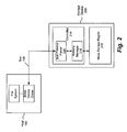
- FIG. 2 is a block diagram that illustrates the general structure of a storage device 200 representative of each of the storage devices 104 and 106 in more detail in accordance with one embodiment of the present invention.
- storage device 200 may be a conventional or legacy storage device.
- the storage device 200 may be either a removable or a non-removable device.
- the storage device 200 is a conventional removable FLASH memory card and generally includes a memory controller 214 and a mass storage region 216.
- the memory controller 214 includes a memory manager 218 and protocol parser 220.
- the protocol parser 220 is configured to analyze communications sent over the bus 108. More specifically, the protocol parser 220 is configured to analyze a communication sent from the host 102 and determine whether storage device 200 is an intended target of the bus communication based on a device identifier or address specified as part of the communication. If the bus communication is a memory operation directed towards storage device 200, the communication is passed to the memory manager 218 which in turn performs the requested operation accessing mass storage region 216. Other instructions directed at the storage device 200 are responded to by either the protocol parser 220 or the memory manager 218 as appropriate. Instructions and communications directed at other devices are generally simply ignored by storage devices 200.
- the storage device identifier is preferably a permanent device identifier associated with the targeted storage device.
- a permanent device identifier associated with the targeted storage device.
- many types of storage devices such as FLASH memory cards have an associated permanent device identifier that may be used for this purpose.
- a device identifier assigned by the host 102 may be used.
- a single physical device may include two or more addressable storage regions (or devices) within the physical device. In this case, each storage region may have a corresponding device identifier and/or set of logical addresses.
- a broadcast identifier that indicates that the command was addressed to all devices on the bus, or a list of all of the targeted device identifiers may be used.
- a communication such as a command transmitted from the host 102 includes an operation identifier that identifies the type of bus protocol operation to be performed.
- the identified operations may be memory operations such as read, write and erase operations; memory management commands such as an instruction for a targeted storage device to create a partition; initialization and authentication requests; interrupts; acknowledgements; error signals and any other bus related commands or operations.
- the host 102 controls various operations of the storage devices 104 and 106.
- the host transmits commands to the storage devices instructing the storage device to write data, read data and erase along with other housekeeping operations. Commands are communicated from the host 102 over the bus 108 to one or more targeted storage devices connected with the bus. Only the storage device(s) targeted by a given command (e.g., by a device identifier and/or address within the command) accepts the command and executes an operation based on the command. It should be noted that, in the described embodiments, only the host 102 is capable of transmitting commands over the bus 108.
- Process 300 begins at 302 with host 102 sending a LISTEN/WRITE command over bus 108 targeting storage device 106 and instructing storage device 106 to listen to the bus and write data from the bus into the device's memory.
- the LISTEN/WRITE command instructs storage device 106 to begin listening to the bus 108 at a specific time T1 and write data from the bus after time T1 into the device's memory.
- the host 102 may instruct the storage device 106 to begin listening to the bus 108 at a specific time slot X1.
- the slave device 106 can be instructed to start listening immediately and wait until data is available on the bus 108 to write.
- Host 102 also sends a READ command over bus 108 at 304 targeting storage device 104 and instructing storage device 104 to read data from the device's memory and to output the data onto bus 108.
- the READ command instructs storage device 104 to begin reading and outputting data onto the bus 108 at a specific time, preferably at or after T1 so as to not lose any data.
- the host 102 may instruct the storage device 104 to begin reading and outputting data onto the bus 108 at the specific time slot X1.
- the slave device 104 is instructed to read and output data onto the bus immediately.
- storage device 106 pulls the data directly output from storage device 104 from the bus 108 and writes the data into memory. More particularly, unlike in conventional arrangements, the data output from storage device 104 is not first temporarily cached in the host 102 or in any other device prior to being pulled from bus 108 and written into storage device 106. Thus, while the host 102 initiates the transaction of data between storage device 104 and storage device 106, the host 102 is not involved in storing and/or transmitting data.
- the invention circumvents this conventional paradigm. That is, the invention enables the direct transfer of data between storage device 104 and 106 while enabling the use of legacy devices and master/slave protocols as each storage device presumes that the data it is sending or receiving over the bus 108 is being sent to or received from the host 102.
- the total quantity of data transmitted over the bus 108 may be approximately cut in half; that is, since data may be written directly from one storage device to another storage device, rather than first cached and then re-transmitted by the caching device, the amount of data transmitted over the bus 108 for a given transaction may be roughly cut in half and hence, the total bandwidth required may be similarly reduced.
- the data transfer rate between the storage devices themselves may be increased and, furthermore, the processor requirements of the host 102 may be reduced.
- storage device 104 continues reading and outputting data onto the bus 108 until such time as the host 102 issues a STOP_READING command at 306 targeting device 104 and instructing storage device 104 to stop reading and outputting data onto the bus 108.
- storage device 106 continues pulling data from the bus 108 until such time as the host 102 issues a STOP_LISTENING command at 308 targeting device 106 and instructing storage device 106 to stop pulling data from the bus.
- the READ command also instructs storage device 104 to continue outputting data onto the bus 108 until such point as a duration D1 has elapsed.
- the LISTEN/WRITE command may also instruct storage device 106 to continue pulling data from the bus 108 until a duration D2 has elapsed.
- D2 is at least as long as D1 so as to not lose any data.
- the host 102 knows the amount of data to be transferred (e.g., the number of bits) and the operating frequency of the bus 108, then the host can calculate the duration of time needed to transfer the data and subsequently instruct storage device 104 to output data for this duration and instruct storage device 106 to continue listening and writing the data for this duration.
- the LISTEN/WRITE command instructs storage device 106 to listen to the bus 108 during specific time slots Xn, which may or may not be consecutive. Data on the bus 108 during the time slots Xn are then written into the device's memory.
- the READ command similarly instructs storage device 104 to begin reading and outputting data onto the bus 108 during the specific time slots Xn. Again, it should be noted that the time slots may not be consecutive. More particularly, the host 102 may instruct the storage device 104 to output data A onto the bus 108 in time slots X1, X2, X3 and X4 which, again, may not in some embodiments be consecutive. The host 102 would then instruct storage device 106 to listen and pull data from the bus 108 during time slots X1, X2, X3 and X4.
- process 300 was described with reference to transferring data from a single storage device 104 to another single storage device 106, it should be appreciated that the host 102 may issue a multicast or broadcast command instructing a plurality of storage devices to listen to the bus at specific times and write the associated data to memory. In this way, multiple copies of the data can be stored on a plurality of devices simultaneously.
- a first slave device coupled with a bus may be a network card acting as a network bridge to an external network or protocol, such as WiMax, Wi-Fi or Bluetooth, and the second slave device may be a storage device coupled with the bus.
- a master device may instruct the first slave device to directly pass data it receives or has received from an external network through the bus to the second slave device, or instruct the second slave device to send data to the first slave device to be communicated over the external network.
- the network card may be using SDIO protocol.
- each device including slave storage devices 404, 406 and 408, is connected serially in a daisy chain arrangement.
- a daisy chain arrangement Such an arrangement may be desirable in various high speed consumer electronics applications, among others.
- three storage devices are shown in the embodiment illustrated in Figure 4 , it will be appreciated that more or fewer devices may be arranged in the daisy chain arrangement. In general, two to five devices are typically connected in such an arrangement.
- daisy chain arrangement it is meant that pins of one device are electrically connected to pins of a neighboring device.
- the connection can be either by hard soldering, by a printed circuit layout or by connection of socket pins.
- a second set of pins from storage device 404 can be connected to a first set of pins from storage device 406 via a set of communication lines 432
- a second set of pins of storage device 406 can be connected to a first set of pins of storage device 408 via a set of communication lines 434, and so on.
- all of the storage devices other than the first and last device in the daisy chain arrangement are connected to two immediately adjacent neighboring devices.
- the first set of pins of storage device 404 are connected via a set of communication lines 430 with host 402 serving as the master device.
- all of the storage devices share a clock; however, this is not a requirement as each device may generate its own clock.
- each device passes to the next device downstream in the chain the commands from the host 402 that are not addressed to itself. That is, each storage device (e.g., storage devices 406 and 408) other than the first device in the chain (e.g., storing device 404) is coupled to the host 402 by means of any upstream devices in the chain. That is, communications or information passed from the host 402 to a particular storage device must first pass sequentially through all other upstream devices in the chain.
- the storage devices 404, 406 and 408 along with communication lines 430, 432 and 434 form a virtual communication bus that serves to pass communications and information from the host to the storage devices and from the storage devices to the host.
- a host 402 may transmit a LISTEN/WRITE command down the string of daisy-chained devices.
- host 402 may transmit a LISTEN/WRITE command targeting storage device 406 over communication lines 430 where it is first received by storage device 404.
- Storage device 404 may then pass the LISTEN/WRITE command over communication lines 432 where the command is then received at target storage device 406.
- the LISTEN/WRITE command may instruct the storage device 406 to listen to communication lines 434 at a specific time and to write data from the communication lines 434 beginning at the specific time.
- Host 402 may also transmit a READ command targeting storage device 408 over communication lines 430.
- the READ command may be passed by storage devices 404 and 406 and along communication lines 432 and 434 before reaching target storage device 408 and may instruct storage device 408 to read data from memory and output the data onto communication lines 434 at a specific time.
- storage device 406 may listen to the communication lines 434 at the specific time instructed by the LISTEN/WRITE command and write the data it pulls from the communication lines 434, which has been directly read from storage device 408 and output onto communication lines 434 by storage device 408, without first having the data be transferred to the host 402.
- the storage devices 404, 406 and 408 could be arranged into a daisy chain configuration as in Figure 4 while a separate common bus interconnects the storage devices with themselves and to the host 402.
- a separate common bus interconnects the storage devices with themselves and to the host 402.
Landscapes
- Engineering & Computer Science (AREA)
- Theoretical Computer Science (AREA)
- Physics & Mathematics (AREA)
- General Engineering & Computer Science (AREA)
- General Physics & Mathematics (AREA)
- Computer Networks & Wireless Communication (AREA)
- Signal Processing (AREA)
- Information Transfer Systems (AREA)
- Small-Scale Networks (AREA)
Claims (5)
- Verfahren zum Übertragen von Daten über einen gemeinsam genutzten Bus (108), der eine Mehrzahl von Kommunikationsleitungen (108) enthält, die ein erstes adressierbares Ziel-Slave-Gerät (104), das zum Speichern von Daten konfiguriert ist, ein zweites adressierbares Quell-Slave-Gerät (106), das zum Speichern von Daten konfiguriert ist und auf dem erste Daten gespeichert sind, und ein Master-Gerät (102), das zum Verwalten des ersten Slave-Geräts (104) und des zweiten Slave-Geräts (106) angeordnet ist, verbinden, wobei das Verfahren umfasst:Senden eines ersten Befehls vom Master-Gerät (104), das mit dem gemeinsam genutzten Bus (108) verbunden ist, an das erste Ziel-Slave-Gerät (104), das mit dem gemeinsam genutzten Bus (108) verbunden ist, wobei der erste Befehl das erste Ziel-Slave-Gerät (104) anweist, Daten aus dem gemeinsam genutzten Bus (108) empfangsbereit abzuhören und zu schreiben, beginnend zu einem ersten Zeitpunkt, bis eine Zeitdauer D2 verstrichen ist; undSenden eines zweiten Befehls vom Master-Gerät (102) an das zweite Quell-Slave-Device (106), das mit dem gemeinsam genutzten Bus (108) verbunden ist, wobei der zweite Befehl das zweite Quell-Slave-Gerät (106) anweist, erste Daten zu lesen und auf dem gemeinsam genutzten Bus (108) auszugeben, beginnend zu oder nach dem ersten Zeitpunkt, bis eine Zeitdauer D1 verstrichen ist, wobei D1 auf einer Menge von zu übertragende Daten basiert und auch auf einer Betriebsfrequenz der Mehrzahl von Kommunilcationsleitungen (108) basiert, und wobei D2 zumindest genauso lang wie D1 ist;wobei die erste Datenausgabe von dem zweiten Quell-Slave-Gerät (106), beginnend zum ersten Zeitpunkt, vom ersten Ziel-Slave-Gerät (104) gespeichert wird, beginnend zum ersten Zeitpunkt, ohne dass die ersten Daten zuerst an das Master-Gerät (102) oder ein anderes Speichergerät übertragen werden müssen,wobei das Master-Gerät (102) ein Host-Gerät ist, und wobei das erste Slave-Gerät (104) und das zweite Slave-Gerät (106) lokale Speichergeräte (200) sind,wobei zumindest eines des ersten Slave-Geräts (104) und des zweiten Slave-Geräts (106) ein entfernbarer Gerät ist, das zum sofortigen Entfernen von diversen Kommunikationsleitungen und zum sofortigen Hinzufügen zu diesen konfiguriert ist,wobei der erste Befehl an mehrere Slave-Geräte (104, 106), einschließlich des ersten Slave-Geräts (104), im Wesentlichen gleichzeitig per Multicast oder Broadcast übertragen wird, undwobei der erste Befehl zumindest eine Mehrzahl der mehreren Slave-Geräte (104, 106) anweist, Daten aus den Kommunikationsleitungen (108) empfangsbereit abzuhören und zu schreiben, beginnend zum ersten Zeitpunkt, so dass die ersten Daten von der Mehrzahl der mehreren Slave-Geräte (104, 106) im Wesentlichen gleichzeitig gespeichert werden können.
- Verfahren nach Anspruch 1, ferner umfassend das Senden eines dritten Befehls vom Master-Gerät (102) an das zweite Slave-Gerät (106), der das zweite Slave-Gerät (106) anweist, die Ausgabe von Daten auf die Kommunikationsleitungen (108) zu einem zweiten Zeitpunkt zu stoppen; und
Senden eines vierten Befehls vom Master-Gerät (102) an das erste Slave-Gerät (104), der das erste Slave-Gerät (104) anweist, das empfangsbereite Abhören der Kommunikationsleitungen (108) zu oder nach dem zweiten Zeitpunkt zu stoppen. - Verfahren nach Anspruch 1, ferner umfassend:Teilen der Zeitdauer D2 in eine Mehrzahl von Zeitfenstern, wobei jedwede Daten auf der Mehrzahl von Komnnunikationsleituttgen (108) von dem ersten Slave-Gerät (104) nur während der Mehrzahl von Zeitfenstern empfangen und gespeichert werden.
- Verfahren nach Anspruch 3, wobei das erste Slave-Gerät (104) nicht weiß, dass die ersten Daten direkt von dem zweiten Slave-Gerät (106) und nicht vom Master-Gerät (102) kommen.
- Verfahren nach einem der Ansprüche 3 bis 4, wobei das erste Slave-Gerät (404) und die das zweite Slave-Gerät (406) zwei einer Mehrzahl von adressierbaren Geräten (404, 406, 408) sind, die in Daisy-Chain-Konfiguration angeordnet sind, so dass jedes der adressierbaren Geräte (404, 406, 408) über eine oder mehrere der Kommunikationsleitungen (430, 432, 434) mit zumindest einem benachbarten Gerät (404, 406, 408) verbunden ist, wobei jedes Gerät (404, 406, 408) mit nicht mehr als zwei direkt miteinander benachbarten Geräten (404, 406, 408) verbunden ist, und wobei jedes Gerät (404, 406, 408), bei dem es sich nicht um das letzte Gerät in der Kette handelt, Kommunikationen, einschließlich Befehle, die nicht an das Gerät selbst gerichtet sind, über die Kommunikationsleitungen (430, 432, 434), die benachbarte Geräte (404, 406, 408) miteinander verbinden, an das nächste Gerät (404, 406, 408) weiterleitet.
Applications Claiming Priority (2)
| Application Number | Priority Date | Filing Date | Title |
|---|---|---|---|
| US12/101,821 US7809873B2 (en) | 2008-04-11 | 2008-04-11 | Direct data transfer between slave devices |
| PCT/IB2009/005138 WO2009125268A1 (en) | 2008-04-11 | 2009-04-01 | Direct data transfer between slave devices |
Publications (2)
| Publication Number | Publication Date |
|---|---|
| EP2263155A1 EP2263155A1 (de) | 2010-12-22 |
| EP2263155B1 true EP2263155B1 (de) | 2012-10-17 |
Family
ID=40792909
Family Applications (1)
| Application Number | Title | Priority Date | Filing Date |
|---|---|---|---|
| EP09730967A Not-in-force EP2263155B1 (de) | 2008-04-11 | 2009-04-01 | Direkte datenübertragung zwischen nebengeräten |
Country Status (7)
| Country | Link |
|---|---|
| US (2) | US7809873B2 (de) |
| EP (1) | EP2263155B1 (de) |
| JP (1) | JP4843747B2 (de) |
| KR (1) | KR20110010707A (de) |
| CN (1) | CN102057363B (de) |
| TW (1) | TWI482022B (de) |
| WO (1) | WO2009125268A1 (de) |
Families Citing this family (60)
| Publication number | Priority date | Publication date | Assignee | Title |
|---|---|---|---|---|
| GB0028353D0 (en) * | 2000-11-21 | 2001-01-03 | Aspex Technology Ltd | Improvements relating to digital data communications |
| US8127147B2 (en) * | 2005-05-10 | 2012-02-28 | Seagate Technology Llc | Method and apparatus for securing data storage while insuring control by logical roles |
| TWI339797B (en) * | 2007-06-23 | 2011-04-01 | Princeton Technology Corp | Data storage system |
| US8713697B2 (en) | 2008-07-09 | 2014-04-29 | Lennox Manufacturing, Inc. | Apparatus and method for storing event information for an HVAC system |
| US8527096B2 (en) | 2008-10-24 | 2013-09-03 | Lennox Industries Inc. | Programmable controller and a user interface for same |
| US8802981B2 (en) | 2008-10-27 | 2014-08-12 | Lennox Industries Inc. | Flush wall mount thermostat and in-set mounting plate for a heating, ventilation and air conditioning system |
| US8655491B2 (en) | 2008-10-27 | 2014-02-18 | Lennox Industries Inc. | Alarm and diagnostics system and method for a distributed architecture heating, ventilation and air conditioning network |
| US8874815B2 (en) | 2008-10-27 | 2014-10-28 | Lennox Industries, Inc. | Communication protocol system and method for a distributed architecture heating, ventilation and air conditioning network |
| US8788100B2 (en) | 2008-10-27 | 2014-07-22 | Lennox Industries Inc. | System and method for zoning a distributed-architecture heating, ventilation and air conditioning network |
| US8798796B2 (en) | 2008-10-27 | 2014-08-05 | Lennox Industries Inc. | General control techniques in a heating, ventilation and air conditioning network |
| US8855825B2 (en) | 2008-10-27 | 2014-10-07 | Lennox Industries Inc. | Device abstraction system and method for a distributed-architecture heating, ventilation and air conditioning system |
| US9432208B2 (en) | 2008-10-27 | 2016-08-30 | Lennox Industries Inc. | Device abstraction system and method for a distributed architecture heating, ventilation and air conditioning system |
| US8295981B2 (en) | 2008-10-27 | 2012-10-23 | Lennox Industries Inc. | Device commissioning in a heating, ventilation and air conditioning network |
| US8762666B2 (en) | 2008-10-27 | 2014-06-24 | Lennox Industries, Inc. | Backup and restoration of operation control data in a heating, ventilation and air conditioning network |
| US8564400B2 (en) | 2008-10-27 | 2013-10-22 | Lennox Industries, Inc. | Communication protocol system and method for a distributed-architecture heating, ventilation and air conditioning network |
| US9632490B2 (en) | 2008-10-27 | 2017-04-25 | Lennox Industries Inc. | System and method for zoning a distributed architecture heating, ventilation and air conditioning network |
| US8437878B2 (en) | 2008-10-27 | 2013-05-07 | Lennox Industries Inc. | Alarm and diagnostics system and method for a distributed architecture heating, ventilation and air conditioning network |
| US8725298B2 (en) | 2008-10-27 | 2014-05-13 | Lennox Industries, Inc. | Alarm and diagnostics system and method for a distributed architecture heating, ventilation and conditioning network |
| US8442693B2 (en) | 2008-10-27 | 2013-05-14 | Lennox Industries, Inc. | System and method of use for a user interface dashboard of a heating, ventilation and air conditioning network |
| US9678486B2 (en) | 2008-10-27 | 2017-06-13 | Lennox Industries Inc. | Device abstraction system and method for a distributed-architecture heating, ventilation and air conditioning system |
| US8600559B2 (en) | 2008-10-27 | 2013-12-03 | Lennox Industries Inc. | Method of controlling equipment in a heating, ventilation and air conditioning network |
| US8615326B2 (en) | 2008-10-27 | 2013-12-24 | Lennox Industries Inc. | System and method of use for a user interface dashboard of a heating, ventilation and air conditioning network |
| US8452456B2 (en) | 2008-10-27 | 2013-05-28 | Lennox Industries Inc. | System and method of use for a user interface dashboard of a heating, ventilation and air conditioning network |
| US8977794B2 (en) | 2008-10-27 | 2015-03-10 | Lennox Industries, Inc. | Communication protocol system and method for a distributed-architecture heating, ventilation and air conditioning network |
| US9325517B2 (en) | 2008-10-27 | 2016-04-26 | Lennox Industries Inc. | Device abstraction system and method for a distributed-architecture heating, ventilation and air conditioning system |
| US8600558B2 (en) | 2008-10-27 | 2013-12-03 | Lennox Industries Inc. | System recovery in a heating, ventilation and air conditioning network |
| US8744629B2 (en) | 2008-10-27 | 2014-06-03 | Lennox Industries Inc. | System and method of use for a user interface dashboard of a heating, ventilation and air conditioning network |
| US8452906B2 (en) | 2008-10-27 | 2013-05-28 | Lennox Industries, Inc. | Communication protocol system and method for a distributed-architecture heating, ventilation and air conditioning network |
| US8463442B2 (en) | 2008-10-27 | 2013-06-11 | Lennox Industries, Inc. | Alarm and diagnostics system and method for a distributed architecture heating, ventilation and air conditioning network |
| US8774210B2 (en) | 2008-10-27 | 2014-07-08 | Lennox Industries, Inc. | Communication protocol system and method for a distributed-architecture heating, ventilation and air conditioning network |
| US8437877B2 (en) | 2008-10-27 | 2013-05-07 | Lennox Industries Inc. | System recovery in a heating, ventilation and air conditioning network |
| US8433446B2 (en) | 2008-10-27 | 2013-04-30 | Lennox Industries, Inc. | Alarm and diagnostics system and method for a distributed-architecture heating, ventilation and air conditioning network |
| US8560125B2 (en) | 2008-10-27 | 2013-10-15 | Lennox Industries | Communication protocol system and method for a distributed-architecture heating, ventilation and air conditioning network |
| US8655490B2 (en) | 2008-10-27 | 2014-02-18 | Lennox Industries, Inc. | System and method of use for a user interface dashboard of a heating, ventilation and air conditioning network |
| US8548630B2 (en) | 2008-10-27 | 2013-10-01 | Lennox Industries, Inc. | Alarm and diagnostics system and method for a distributed-architecture heating, ventilation and air conditioning network |
| US8543243B2 (en) | 2008-10-27 | 2013-09-24 | Lennox Industries, Inc. | System and method of use for a user interface dashboard of a heating, ventilation and air conditioning network |
| US8463443B2 (en) | 2008-10-27 | 2013-06-11 | Lennox Industries, Inc. | Memory recovery scheme and data structure in a heating, ventilation and air conditioning network |
| US8892797B2 (en) | 2008-10-27 | 2014-11-18 | Lennox Industries Inc. | Communication protocol system and method for a distributed-architecture heating, ventilation and air conditioning network |
| US9651925B2 (en) | 2008-10-27 | 2017-05-16 | Lennox Industries Inc. | System and method for zoning a distributed-architecture heating, ventilation and air conditioning network |
| US8694164B2 (en) | 2008-10-27 | 2014-04-08 | Lennox Industries, Inc. | Interactive user guidance interface for a heating, ventilation and air conditioning system |
| US8661165B2 (en) * | 2008-10-27 | 2014-02-25 | Lennox Industries, Inc. | Device abstraction system and method for a distributed architecture heating, ventilation and air conditioning system |
| US8994539B2 (en) | 2008-10-27 | 2015-03-31 | Lennox Industries, Inc. | Alarm and diagnostics system and method for a distributed-architecture heating, ventilation and air conditioning network |
| US8156274B2 (en) * | 2009-02-02 | 2012-04-10 | Standard Microsystems Corporation | Direct slave-to-slave data transfer on a master-slave bus |
| CN101930788A (zh) * | 2009-06-24 | 2010-12-29 | 鸿富锦精密工业(深圳)有限公司 | 移动存储设备及具有移动存储设备的存储装置 |
| TWI405086B (zh) * | 2009-12-31 | 2013-08-11 | 具資訊安全管控之通用匯流排連接裝置 | |
| US20120051359A1 (en) * | 2010-08-30 | 2012-03-01 | O'brien John | Apparatus and method to manage multicast data transfers in a multiple storage element system that contains data storage |
| JP5805546B2 (ja) * | 2012-01-13 | 2015-11-04 | ルネサスエレクトロニクス株式会社 | 半導体装置 |
| TWI456398B (zh) * | 2012-07-03 | 2014-10-11 | Acer Inc | 支援雙主控裝置的資料路由系統 |
| WO2014174548A1 (en) * | 2013-04-22 | 2014-10-30 | Hitachi, Ltd. | Storage apparatus and data copy control method |
| US9892077B2 (en) * | 2013-10-07 | 2018-02-13 | Qualcomm Incorporated | Camera control interface slave device to slave device communication |
| KR102238650B1 (ko) | 2014-04-30 | 2021-04-09 | 삼성전자주식회사 | 저장 장치, 상기 저장 장치를 포함하는 컴퓨팅 시스템 및 상기 저장 장치의 동작 방법 |
| US9389972B2 (en) | 2014-05-13 | 2016-07-12 | International Business Machines Corporation | Data retrieval from stacked computer memory |
| US9405468B2 (en) | 2014-05-13 | 2016-08-02 | Globalfoundries Inc. | Stacked memory device control |
| KR102225249B1 (ko) * | 2014-06-28 | 2021-03-08 | 인텔 코포레이션 | 전자 디바이스용 센서 버스 인터페이스 |
| US9830280B2 (en) * | 2015-06-22 | 2017-11-28 | Qualcomm Incorporated | Multiple access single SDIO interface with multiple SDIO units |
| US10229086B2 (en) * | 2015-12-26 | 2019-03-12 | Intel Corporation | Technologies for automatic timing calibration in an inter-integrated circuit data bus |
| US10346324B2 (en) * | 2017-02-13 | 2019-07-09 | Microchip Technology Incorporated | Devices and methods for autonomous hardware management of circular buffers |
| WO2020068094A1 (en) * | 2018-09-28 | 2020-04-02 | Hewlett-Packard Development Company, L.P. | Regeneration and propagation of a signal between communication units |
| US10936234B2 (en) * | 2019-05-22 | 2021-03-02 | Macronix International Co., Ltd. | Data transfer between memory devices on shared bus |
| CN117891771B (zh) * | 2024-03-14 | 2024-05-28 | 艾德克斯电子(南京)有限公司 | 一种多模组数据交互设备 |
Citations (3)
| Publication number | Priority date | Publication date | Assignee | Title |
|---|---|---|---|---|
| US5761462A (en) * | 1996-12-13 | 1998-06-02 | International Business Machines Corporation | Method and system for supporting peripheral component interconnect (PCI) peer-to-peer access across multiple PCI host bridges within a data-processing system |
| US6128711A (en) * | 1996-11-12 | 2000-10-03 | Compaq Computer Corporation | Performance optimization and system bus duty cycle reduction by I/O bridge partial cache line writes |
| WO2003005640A2 (en) * | 2001-07-06 | 2003-01-16 | Intel Corporation | Method and apparatus for peer-to-peer services |
Family Cites Families (39)
| Publication number | Priority date | Publication date | Assignee | Title |
|---|---|---|---|---|
| US4740916A (en) * | 1985-12-19 | 1988-04-26 | International Business Machines Corporation | Reconfigurable contiguous address space memory system including serially connected variable capacity memory modules and a split address bus |
| JPH03177953A (ja) * | 1989-12-07 | 1991-08-01 | Yokogawa Medical Syst Ltd | データ転送方式 |
| EP0562251A2 (de) * | 1992-03-24 | 1993-09-29 | Universities Research Association, Inc. | Durch ein dynamisches wiederkonfigurierbares serielles Netzwerk gesteuertes Paralleldatenübertragungsnetzwerk |
| US5467295A (en) * | 1992-04-30 | 1995-11-14 | Intel Corporation | Bus arbitration with master unit controlling bus and locking a slave unit that can relinquish bus for other masters while maintaining lock on slave unit |
| US5522050A (en) | 1993-05-28 | 1996-05-28 | International Business Machines Corporation | Bus-to-bus bridge for a multiple bus information handling system that optimizes data transfers between a system bus and a peripheral bus |
| US5991835A (en) * | 1994-11-22 | 1999-11-23 | Teac Corporation | Peripheral data storage device in which time interval used for data transfer from relatively fast buffer memory to relatively slower main memory is selected in view of average of time intervals during which data blocks were recently received from host |
| US5867733A (en) | 1996-06-04 | 1999-02-02 | Micron Electronics, Inc. | Mass data storage controller permitting data to be directly transferred between storage devices without transferring data to main memory and without transferring data over input-output bus |
| US6434620B1 (en) * | 1998-08-27 | 2002-08-13 | Alacritech, Inc. | TCP/IP offload network interface device |
| US6408369B1 (en) * | 1998-03-12 | 2002-06-18 | Emc Corporation | Internal copy for a storage controller |
| EP0983555A1 (de) | 1998-03-20 | 2000-03-08 | Raymond Horn | Adressierungsschema zur verdoppelung der übertragungsleistung einer mastergesteuerten slave-to-slave-kommunikation in einem beliebigen bussystem |
| US6640269B1 (en) * | 1998-06-19 | 2003-10-28 | Cisco Technology, Inc. | Method and apparatus for assisting communication of information between two processes |
| US6034882A (en) * | 1998-11-16 | 2000-03-07 | Matrix Semiconductor, Inc. | Vertically stacked field programmable nonvolatile memory and method of fabrication |
| US6425032B1 (en) | 1999-04-15 | 2002-07-23 | Lucent Technologies Inc. | Bus controller handling a dynamically changing mix of multiple nonpre-emptable periodic and aperiodic devices |
| US6839393B1 (en) * | 1999-07-14 | 2005-01-04 | Rambus Inc. | Apparatus and method for controlling a master/slave system via master device synchronization |
| EP1087293A3 (de) * | 1999-09-24 | 2006-02-01 | Hitachi, Ltd. | Ein Rechnersystem und ein Programminstallierungsverfahren davon |
| US20010049726A1 (en) * | 2000-06-02 | 2001-12-06 | Guillaume Comeau | Data path engine |
| EP1237090A1 (de) * | 2001-02-28 | 2002-09-04 | Alcatel | Serielles Peripherieschnittstellenmastergerät, serielles Peripherieschnittstellenslavegerät und serielle Peripherieschnittstelle |
| US6820152B2 (en) * | 2001-04-25 | 2004-11-16 | Matsushita Electric Industrial Co., Ltd. | Memory control device and LSI |
| JP2002351825A (ja) * | 2001-05-29 | 2002-12-06 | Rohm Co Ltd | 通信システム |
| US7805725B2 (en) * | 2002-09-26 | 2010-09-28 | Siemens Industry, Inc. | System and method for synchronizing system modules |
| US20040148450A1 (en) * | 2003-01-27 | 2004-07-29 | Shih-Chang Chen | Serially connectable USB drive |
| US7334234B2 (en) * | 2003-04-28 | 2008-02-19 | International Business Machines Corporation | Method and apparatus for transferring data to virtual devices behind a bus expander |
| US20050086413A1 (en) * | 2003-10-15 | 2005-04-21 | Super Talent Electronics Inc. | Capacity Expansion of Flash Memory Device with a Daisy-Chainable Structure and an Integrated Hub |
| US6993618B2 (en) * | 2004-01-15 | 2006-01-31 | Super Talent Electronics, Inc. | Dual-mode flash storage exchanger that transfers flash-card data to a removable USB flash key-drive with or without a PC host |
| JP2005215953A (ja) * | 2004-01-29 | 2005-08-11 | Matsushita Electric Ind Co Ltd | 情報処理装置 |
| KR100445182B1 (ko) * | 2004-03-05 | 2004-08-21 | 주식회사 넥스토디아이 | 데이터 복사장치 |
| US8375146B2 (en) | 2004-08-09 | 2013-02-12 | SanDisk Technologies, Inc. | Ring bus structure and its use in flash memory systems |
| EP1811395A4 (de) * | 2004-09-28 | 2008-01-02 | Zentek Technology Japan Inc | Host-controller |
| US20060069888A1 (en) * | 2004-09-29 | 2006-03-30 | International Business Machines (Ibm) Corporation | Method, system and program for managing asynchronous cache scans |
| JP4964946B2 (ja) * | 2006-04-20 | 2012-07-04 | ライフスキャン・スコットランド・リミテッド | 血中グルコースシステムにおけるデータ送信方法および対応する血中グルコースシステム |
| DE102006055514A1 (de) * | 2006-05-24 | 2007-11-29 | Robert Bosch Gmbh | Gateway zum Datentransfer zwischen seriellen Bussen |
| US7451265B2 (en) * | 2006-08-04 | 2008-11-11 | Sandisk Corporation | Non-volatile memory storage systems for phased garbage collection |
| US8117415B2 (en) * | 2006-09-18 | 2012-02-14 | Sandisk Il Ltd. | Storage device estimating a completion time for a storage operation |
| CN101132328A (zh) | 2007-08-15 | 2008-02-27 | 北京航空航天大学 | 实时工业以太网EtherCAT通信控制器 |
| US7752353B2 (en) * | 2007-10-22 | 2010-07-06 | Sandisk Il Ltd. | Signaling an interrupt request through daisy chained devices |
| US7565470B2 (en) * | 2007-12-04 | 2009-07-21 | Holylite Microelectronics Corp. | Serial bus device with address assignment by master device |
| US7979662B2 (en) * | 2007-12-28 | 2011-07-12 | Sandisk Il Ltd. | Storage device with transaction indexing capability |
| US7913030B2 (en) * | 2007-12-28 | 2011-03-22 | Sandisk Il Ltd. | Storage device with transaction logging capability |
| US8187936B2 (en) | 2010-06-30 | 2012-05-29 | SanDisk Technologies, Inc. | Ultrahigh density vertical NAND memory device and method of making thereof |
-
2008
- 2008-04-11 US US12/101,821 patent/US7809873B2/en not_active Ceased
-
2009
- 2009-04-01 WO PCT/IB2009/005138 patent/WO2009125268A1/en not_active Ceased
- 2009-04-01 EP EP09730967A patent/EP2263155B1/de not_active Not-in-force
- 2009-04-01 KR KR1020107024384A patent/KR20110010707A/ko active Granted
- 2009-04-01 CN CN200980121899.XA patent/CN102057363B/zh not_active Expired - Fee Related
- 2009-04-01 JP JP2011503514A patent/JP4843747B2/ja not_active Expired - Fee Related
- 2009-04-09 TW TW098111858A patent/TWI482022B/zh not_active IP Right Cessation
-
2014
- 2014-04-02 US US14/243,570 patent/USRE46488E1/en active Active
Patent Citations (3)
| Publication number | Priority date | Publication date | Assignee | Title |
|---|---|---|---|---|
| US6128711A (en) * | 1996-11-12 | 2000-10-03 | Compaq Computer Corporation | Performance optimization and system bus duty cycle reduction by I/O bridge partial cache line writes |
| US5761462A (en) * | 1996-12-13 | 1998-06-02 | International Business Machines Corporation | Method and system for supporting peripheral component interconnect (PCI) peer-to-peer access across multiple PCI host bridges within a data-processing system |
| WO2003005640A2 (en) * | 2001-07-06 | 2003-01-16 | Intel Corporation | Method and apparatus for peer-to-peer services |
Also Published As
| Publication number | Publication date |
|---|---|
| WO2009125268A1 (en) | 2009-10-15 |
| TW200949552A (en) | 2009-12-01 |
| CN102057363A (zh) | 2011-05-11 |
| KR20110010707A (ko) | 2011-02-07 |
| US7809873B2 (en) | 2010-10-05 |
| CN102057363B (zh) | 2014-10-22 |
| US20090259785A1 (en) | 2009-10-15 |
| EP2263155A1 (de) | 2010-12-22 |
| TWI482022B (zh) | 2015-04-21 |
| USRE46488E1 (en) | 2017-07-25 |
| JP4843747B2 (ja) | 2011-12-21 |
| JP2011518378A (ja) | 2011-06-23 |
Similar Documents
| Publication | Publication Date | Title |
|---|---|---|
| USRE46488E1 (en) | Direct data transfer between slave devices | |
| JP5054818B2 (ja) | インターフェース装置、通信システム、不揮発性記憶装置、通信モード切換方法および集積回路 | |
| CN104428836A (zh) | 环形拓扑状态指示 | |
| US7308523B1 (en) | Flow-splitting and buffering PCI express switch to reduce head-of-line blocking | |
| CN108733600A (zh) | 具有直接存储器访问控制器的电子系统及其操作方法 | |
| WO2005057400A1 (ja) | 電子装置、その制御方法、ホスト装置及びその制御方法 | |
| JP4685800B2 (ja) | スケーラブルなバス構造 | |
| US8891523B2 (en) | Multi-processor apparatus using dedicated buffers for multicast communications | |
| JP4739349B2 (ja) | マルチメディア・カード・インターフェース方法、コンピュータ・プログラム及び装置 | |
| CN106547716A (zh) | 一种面向低管脚数的扩展总线配置系统及方法 | |
| JP2008521080A5 (de) | ||
| KR101192594B1 (ko) | 슬레이브 디바이스 사이에서 직접 데이터를 전송하는 방법 | |
| CN117453117A (zh) | 一种网络存储处理设备、存储服务器、数据存储及读取方法 | |
| US20070131767A1 (en) | System and method for media card communication | |
| CN117499511A (zh) | 报文处理方法、芯片和计算机设备 | |
| CN100527113C (zh) | 多媒体卡接口方法、计算机程序产品和装置 | |
| WO2024012015A1 (zh) | 一种存储系统、主控芯片、数据存储方法及数据读取方法 | |
| CN109885508A (zh) | 高速外设组件互连标准总线系统及其数据传输方法、装置 | |
| JP4567373B2 (ja) | データ転送装置及び通信データ処理システム | |
| CN119363292A (zh) | 一种数据处理方法、装置、计算机设备及存储介质 | |
| CN101164053A (zh) | 可伸缩总线结构 | |
| HK1099823B (en) | Scalable bus structure | |
| HK1133482A (en) | Scalable bus structure | |
| CN117880364A (zh) | 一种数据传输方法、系统以及相关装置 | |
| WO2015024418A1 (zh) | 一种数据拷贝方法、设备和系统 |
Legal Events
| Date | Code | Title | Description |
|---|---|---|---|
| PUAI | Public reference made under article 153(3) epc to a published international application that has entered the european phase |
Free format text: ORIGINAL CODE: 0009012 |
|
| 17P | Request for examination filed |
Effective date: 20101011 |
|
| AK | Designated contracting states |
Kind code of ref document: A1 Designated state(s): AT BE BG CH CY CZ DE DK EE ES FI FR GB GR HR HU IE IS IT LI LT LU LV MC MK MT NL NO PL PT RO SE SI SK TR |
|
| AX | Request for extension of the european patent |
Extension state: AL BA RS |
|
| 17Q | First examination report despatched |
Effective date: 20110321 |
|
| DAX | Request for extension of the european patent (deleted) | ||
| GRAP | Despatch of communication of intention to grant a patent |
Free format text: ORIGINAL CODE: EPIDOSNIGR1 |
|
| GRAS | Grant fee paid |
Free format text: ORIGINAL CODE: EPIDOSNIGR3 |
|
| GRAA | (expected) grant |
Free format text: ORIGINAL CODE: 0009210 |
|
| AK | Designated contracting states |
Kind code of ref document: B1 Designated state(s): AT BE BG CH CY CZ DE DK EE ES FI FR GB GR HR HU IE IS IT LI LT LU LV MC MK MT NL NO PL PT RO SE SI SK TR |
|
| REG | Reference to a national code |
Ref country code: GB Ref legal event code: FG4D |
|
| REG | Reference to a national code |
Ref country code: CH Ref legal event code: EP |
|
| REG | Reference to a national code |
Ref country code: IE Ref legal event code: FG4D |
|
| REG | Reference to a national code |
Ref country code: AT Ref legal event code: REF Ref document number: 580174 Country of ref document: AT Kind code of ref document: T Effective date: 20121115 |
|
| REG | Reference to a national code |
Ref country code: DE Ref legal event code: R096 Ref document number: 602009010499 Country of ref document: DE Effective date: 20121213 |
|
| REG | Reference to a national code |
Ref country code: AT Ref legal event code: MK05 Ref document number: 580174 Country of ref document: AT Kind code of ref document: T Effective date: 20121017 |
|
| REG | Reference to a national code |
Ref country code: NL Ref legal event code: VDEP Effective date: 20121017 |
|
| REG | Reference to a national code |
Ref country code: LT Ref legal event code: MG4D |
|
| PG25 | Lapsed in a contracting state [announced via postgrant information from national office to epo] |
Ref country code: ES Free format text: LAPSE BECAUSE OF FAILURE TO SUBMIT A TRANSLATION OF THE DESCRIPTION OR TO PAY THE FEE WITHIN THE PRESCRIBED TIME-LIMIT Effective date: 20130128 Ref country code: IS Free format text: LAPSE BECAUSE OF FAILURE TO SUBMIT A TRANSLATION OF THE DESCRIPTION OR TO PAY THE FEE WITHIN THE PRESCRIBED TIME-LIMIT Effective date: 20130217 Ref country code: SE Free format text: LAPSE BECAUSE OF FAILURE TO SUBMIT A TRANSLATION OF THE DESCRIPTION OR TO PAY THE FEE WITHIN THE PRESCRIBED TIME-LIMIT Effective date: 20121017 Ref country code: HR Free format text: LAPSE BECAUSE OF FAILURE TO SUBMIT A TRANSLATION OF THE DESCRIPTION OR TO PAY THE FEE WITHIN THE PRESCRIBED TIME-LIMIT Effective date: 20121017 Ref country code: NO Free format text: LAPSE BECAUSE OF FAILURE TO SUBMIT A TRANSLATION OF THE DESCRIPTION OR TO PAY THE FEE WITHIN THE PRESCRIBED TIME-LIMIT Effective date: 20130117 Ref country code: NL Free format text: LAPSE BECAUSE OF FAILURE TO SUBMIT A TRANSLATION OF THE DESCRIPTION OR TO PAY THE FEE WITHIN THE PRESCRIBED TIME-LIMIT Effective date: 20121017 Ref country code: LT Free format text: LAPSE BECAUSE OF FAILURE TO SUBMIT A TRANSLATION OF THE DESCRIPTION OR TO PAY THE FEE WITHIN THE PRESCRIBED TIME-LIMIT Effective date: 20121017 Ref country code: FI Free format text: LAPSE BECAUSE OF FAILURE TO SUBMIT A TRANSLATION OF THE DESCRIPTION OR TO PAY THE FEE WITHIN THE PRESCRIBED TIME-LIMIT Effective date: 20121017 |
|
| PG25 | Lapsed in a contracting state [announced via postgrant information from national office to epo] |
Ref country code: BE Free format text: LAPSE BECAUSE OF FAILURE TO SUBMIT A TRANSLATION OF THE DESCRIPTION OR TO PAY THE FEE WITHIN THE PRESCRIBED TIME-LIMIT Effective date: 20121017 Ref country code: PT Free format text: LAPSE BECAUSE OF FAILURE TO SUBMIT A TRANSLATION OF THE DESCRIPTION OR TO PAY THE FEE WITHIN THE PRESCRIBED TIME-LIMIT Effective date: 20130218 Ref country code: SI Free format text: LAPSE BECAUSE OF FAILURE TO SUBMIT A TRANSLATION OF THE DESCRIPTION OR TO PAY THE FEE WITHIN THE PRESCRIBED TIME-LIMIT Effective date: 20121017 Ref country code: LV Free format text: LAPSE BECAUSE OF FAILURE TO SUBMIT A TRANSLATION OF THE DESCRIPTION OR TO PAY THE FEE WITHIN THE PRESCRIBED TIME-LIMIT Effective date: 20121017 Ref country code: PL Free format text: LAPSE BECAUSE OF FAILURE TO SUBMIT A TRANSLATION OF THE DESCRIPTION OR TO PAY THE FEE WITHIN THE PRESCRIBED TIME-LIMIT Effective date: 20121017 Ref country code: GR Free format text: LAPSE BECAUSE OF FAILURE TO SUBMIT A TRANSLATION OF THE DESCRIPTION OR TO PAY THE FEE WITHIN THE PRESCRIBED TIME-LIMIT Effective date: 20130118 |
|
| PG25 | Lapsed in a contracting state [announced via postgrant information from national office to epo] |
Ref country code: AT Free format text: LAPSE BECAUSE OF FAILURE TO SUBMIT A TRANSLATION OF THE DESCRIPTION OR TO PAY THE FEE WITHIN THE PRESCRIBED TIME-LIMIT Effective date: 20121017 |
|
| PG25 | Lapsed in a contracting state [announced via postgrant information from national office to epo] |
Ref country code: SK Free format text: LAPSE BECAUSE OF FAILURE TO SUBMIT A TRANSLATION OF THE DESCRIPTION OR TO PAY THE FEE WITHIN THE PRESCRIBED TIME-LIMIT Effective date: 20121017 Ref country code: BG Free format text: LAPSE BECAUSE OF FAILURE TO SUBMIT A TRANSLATION OF THE DESCRIPTION OR TO PAY THE FEE WITHIN THE PRESCRIBED TIME-LIMIT Effective date: 20130117 Ref country code: CZ Free format text: LAPSE BECAUSE OF FAILURE TO SUBMIT A TRANSLATION OF THE DESCRIPTION OR TO PAY THE FEE WITHIN THE PRESCRIBED TIME-LIMIT Effective date: 20121017 Ref country code: EE Free format text: LAPSE BECAUSE OF FAILURE TO SUBMIT A TRANSLATION OF THE DESCRIPTION OR TO PAY THE FEE WITHIN THE PRESCRIBED TIME-LIMIT Effective date: 20121017 Ref country code: DK Free format text: LAPSE BECAUSE OF FAILURE TO SUBMIT A TRANSLATION OF THE DESCRIPTION OR TO PAY THE FEE WITHIN THE PRESCRIBED TIME-LIMIT Effective date: 20121017 |
|
| PLBE | No opposition filed within time limit |
Free format text: ORIGINAL CODE: 0009261 |
|
| STAA | Information on the status of an ep patent application or granted ep patent |
Free format text: STATUS: NO OPPOSITION FILED WITHIN TIME LIMIT |
|
| PG25 | Lapsed in a contracting state [announced via postgrant information from national office to epo] |
Ref country code: RO Free format text: LAPSE BECAUSE OF FAILURE TO SUBMIT A TRANSLATION OF THE DESCRIPTION OR TO PAY THE FEE WITHIN THE PRESCRIBED TIME-LIMIT Effective date: 20121017 Ref country code: IT Free format text: LAPSE BECAUSE OF FAILURE TO SUBMIT A TRANSLATION OF THE DESCRIPTION OR TO PAY THE FEE WITHIN THE PRESCRIBED TIME-LIMIT Effective date: 20121017 |
|
| 26N | No opposition filed |
Effective date: 20130718 |
|
| REG | Reference to a national code |
Ref country code: DE Ref legal event code: R097 Ref document number: 602009010499 Country of ref document: DE Effective date: 20130718 |
|
| PG25 | Lapsed in a contracting state [announced via postgrant information from national office to epo] |
Ref country code: MC Free format text: LAPSE BECAUSE OF FAILURE TO SUBMIT A TRANSLATION OF THE DESCRIPTION OR TO PAY THE FEE WITHIN THE PRESCRIBED TIME-LIMIT Effective date: 20121017 Ref country code: CY Free format text: LAPSE BECAUSE OF FAILURE TO SUBMIT A TRANSLATION OF THE DESCRIPTION OR TO PAY THE FEE WITHIN THE PRESCRIBED TIME-LIMIT Effective date: 20121017 |
|
| REG | Reference to a national code |
Ref country code: CH Ref legal event code: PL |
|
| REG | Reference to a national code |
Ref country code: IE Ref legal event code: MM4A |
|
| PG25 | Lapsed in a contracting state [announced via postgrant information from national office to epo] |
Ref country code: CH Free format text: LAPSE BECAUSE OF NON-PAYMENT OF DUE FEES Effective date: 20130430 Ref country code: LI Free format text: LAPSE BECAUSE OF NON-PAYMENT OF DUE FEES Effective date: 20130430 |
|
| REG | Reference to a national code |
Ref country code: FR Ref legal event code: ST Effective date: 20131231 |
|
| PG25 | Lapsed in a contracting state [announced via postgrant information from national office to epo] |
Ref country code: FR Free format text: LAPSE BECAUSE OF NON-PAYMENT OF DUE FEES Effective date: 20130430 |
|
| PG25 | Lapsed in a contracting state [announced via postgrant information from national office to epo] |
Ref country code: IE Free format text: LAPSE BECAUSE OF NON-PAYMENT OF DUE FEES Effective date: 20130401 |
|
| PGFP | Annual fee paid to national office [announced via postgrant information from national office to epo] |
Ref country code: GB Payment date: 20140326 Year of fee payment: 6 |
|
| PGFP | Annual fee paid to national office [announced via postgrant information from national office to epo] |
Ref country code: DE Payment date: 20140417 Year of fee payment: 6 |
|
| PG25 | Lapsed in a contracting state [announced via postgrant information from national office to epo] |
Ref country code: MT Free format text: LAPSE BECAUSE OF FAILURE TO SUBMIT A TRANSLATION OF THE DESCRIPTION OR TO PAY THE FEE WITHIN THE PRESCRIBED TIME-LIMIT Effective date: 20121017 |
|
| PG25 | Lapsed in a contracting state [announced via postgrant information from national office to epo] |
Ref country code: TR Free format text: LAPSE BECAUSE OF FAILURE TO SUBMIT A TRANSLATION OF THE DESCRIPTION OR TO PAY THE FEE WITHIN THE PRESCRIBED TIME-LIMIT Effective date: 20121017 |
|
| PG25 | Lapsed in a contracting state [announced via postgrant information from national office to epo] |
Ref country code: LU Free format text: LAPSE BECAUSE OF NON-PAYMENT OF DUE FEES Effective date: 20130401 Ref country code: HU Free format text: LAPSE BECAUSE OF FAILURE TO SUBMIT A TRANSLATION OF THE DESCRIPTION OR TO PAY THE FEE WITHIN THE PRESCRIBED TIME-LIMIT; INVALID AB INITIO Effective date: 20090401 Ref country code: MK Free format text: LAPSE BECAUSE OF FAILURE TO SUBMIT A TRANSLATION OF THE DESCRIPTION OR TO PAY THE FEE WITHIN THE PRESCRIBED TIME-LIMIT Effective date: 20121017 |
|
| REG | Reference to a national code |
Ref country code: DE Ref legal event code: R119 Ref document number: 602009010499 Country of ref document: DE |
|
| GBPC | Gb: european patent ceased through non-payment of renewal fee |
Effective date: 20150401 |
|
| PG25 | Lapsed in a contracting state [announced via postgrant information from national office to epo] |
Ref country code: DE Free format text: LAPSE BECAUSE OF NON-PAYMENT OF DUE FEES Effective date: 20151103 Ref country code: GB Free format text: LAPSE BECAUSE OF NON-PAYMENT OF DUE FEES Effective date: 20150401 |