EP2263005B1 - Procédé et appareil pour stocker de l'énergie - Google Patents
Procédé et appareil pour stocker de l'énergie Download PDFInfo
- Publication number
- EP2263005B1 EP2263005B1 EP08852400.4A EP08852400A EP2263005B1 EP 2263005 B1 EP2263005 B1 EP 2263005B1 EP 08852400 A EP08852400 A EP 08852400A EP 2263005 B1 EP2263005 B1 EP 2263005B1
- Authority
- EP
- European Patent Office
- Prior art keywords
- storing unit
- weight
- period
- storing
- energy
- Prior art date
- Legal status (The legal status is an assumption and is not a legal conclusion. Google has not performed a legal analysis and makes no representation as to the accuracy of the status listed.)
- Active
Links
Images


Classifications
-
- F—MECHANICAL ENGINEERING; LIGHTING; HEATING; WEAPONS; BLASTING
- F03—MACHINES OR ENGINES FOR LIQUIDS; WIND, SPRING, OR WEIGHT MOTORS; PRODUCING MECHANICAL POWER OR A REACTIVE PROPULSIVE THRUST, NOT OTHERWISE PROVIDED FOR
- F03G—SPRING, WEIGHT, INERTIA OR LIKE MOTORS; MECHANICAL-POWER PRODUCING DEVICES OR MECHANISMS, NOT OTHERWISE PROVIDED FOR OR USING ENERGY SOURCES NOT OTHERWISE PROVIDED FOR
- F03G3/00—Other motors, e.g. gravity or inertia motors
-
- Y—GENERAL TAGGING OF NEW TECHNOLOGICAL DEVELOPMENTS; GENERAL TAGGING OF CROSS-SECTIONAL TECHNOLOGIES SPANNING OVER SEVERAL SECTIONS OF THE IPC; TECHNICAL SUBJECTS COVERED BY FORMER USPC CROSS-REFERENCE ART COLLECTIONS [XRACs] AND DIGESTS
- Y02—TECHNOLOGIES OR APPLICATIONS FOR MITIGATION OR ADAPTATION AGAINST CLIMATE CHANGE
- Y02E—REDUCTION OF GREENHOUSE GAS [GHG] EMISSIONS, RELATED TO ENERGY GENERATION, TRANSMISSION OR DISTRIBUTION
- Y02E60/00—Enabling technologies; Technologies with a potential or indirect contribution to GHG emissions mitigation
- Y02E60/16—Mechanical energy storage, e.g. flywheels or pressurised fluids
Definitions
- the invention relates to a method and apparatus for storing energy.
- the source of energy can be either a power plant generating electricity at a more or less constant level or some form of intermittent energy source, such as a solar powered energy source or a wind powered energy source.
- a system for generating energy using the difference in elevation between a relatively high elevation and a relatively low elevation, the system comprising a weight; a lifting device for lifting the weight from the relatively low elevation to the relatively high elevation and for enabling lowering of the weight from the relatively high elevation to the relatively low elevation; a generator for producing electrical energy for consumption; means for converting energy produced by said lifting device during lowering of said weight into drive energy for driving said generator; an electric motor for driving said lifting device to provide lifting of said weight and for driving said generator; and an intermittently operating energy source for supplying electrical energy to the electric motor during operation of the energy source to drive the generator and to enable lifting of the weight by the lifting device whereby the weight can be lifted during operation of the energy source to provide potential energy for the system.
- An energy storing system comprises an energy storing system, comprising a plurality of weights, a first storing unit and a second storing unit, wherein the first storing unit is arranged below (i.e. at a lower elevation than) the second storing unit and each of the storing units comprises a guiding track on which weights can be placed and along which weights can be moved, wherein each of said guiding tracks comprises a first portion and a second portion, wherein each second portion is arranged below (i.e.
- a loading unit configured to lift at least one weight from the first storing unit to the second storing unit during a first period thereby converting electrical energy to potential energy, said loading unit further configured to lower said at least one weight from the second storing unit to the first storing unit during a second period, thereby converting potential energy to electrical energy, wherein the loading unit is configured to collect a weight from the second portion of the first storing unit and to place said weight on the first portion of the second storing unit during the first period and to collect a weight from the second portion of the second storing unit and to place said weight on the first portion of the first storing unit during the second period.
- the energy storing system according to the present invention provides for a flexible and scalable system due to the possibility to use a plurality of weights and to operate in a cyclical manner.
- each weight preferably comprises wheels. Those wheels are configured to allow said weight to move from the first, higher portion of said guiding track to the second, lower portion of said guiding track preferably by the action of gravity alone.
- a weight which was placed on the first portion of the second storing unit during the first period will move to the second portion of the second storing unit and be ready for collection at the beginning of the second period.
- the loading mechanism comprises a loading stage having a guiding track configured to cooperate with the respective guiding track of any of the storing units to facilitate direct transfer of the weight between the loading stage and the respective guiding track.
- said energy storing system comprises a multitude of storing units arranged at different heights, whereby an even higher degree of versatility is possible.
- the number of weights transferred during both the first and the second period is equal, whereas the duration of the second period is different from the duration of the first period.
- a method comprises the steps of providing a plurality of weights; providing a first and a second storing unit, wherein the first storing unit is arranged below the second storing unit; lifting at least one weight from the lower storing unit to the upper storing unit during a first period thereby converting electrical energy to potential energy; and lowering said at least one weight from the upper storing unit to the lower storing unit during a second period, wherein the duration of the second period is different from the duration of the first period, thereby converting potential energy to electrical energy.
- the second period is either shorter or longer than the first period so as to be able to provide a higher/lower power level during the second period in comparison to the power level used during the first period.
- the first period is an off-peak electricity period whereas the second period is a peak electricity period.
- Figure 1 is a schematic diagram showing an embodiment of the energy storing system 10 according to the present invention.
- the energy storing system 10 comprises a plurality of weights 12, one of which being indicated in figure 1 .
- the energy storing system 10 further comprises a first storing unit 14 and a second storing unit 16, wherein the first storing unit 14 is arranged below the second storing unit 16.
- Each of the storing units 14, 16 comprises a guiding track 18, 20 on which weights can be placed and along which weights can be moved.
- the first, lower guiding track 18 comprises a first portion 22 and a second portion 24, wherein the second portion 24 is arranged slightly below the first portion 22.
- the second, upper guiding track 20 comprises a first portion 26 and a second portion 28, wherein the second portion 28 is arranged slightly below the first portion 26.
- the energy storing system further comprises a loading unit 30 comprising a loading stage 32. As indicated in figure 1 , said loading stage 32 can be moved up and down in between the first and second storing units 14, 16 in a predominantly vertical direction.
- Shown in the left hand part of figure 1 is the transfer of a weight 12 from the lower portion 24 of the lower storing unit 14 on to the loading stage 32 (indicated by an arrow). Said weight 12 on loading stage 32 can then be lifted up to the second storing unit 16. To this end, the loading stage 32 is raised to and aligned with the first, upper portion 26 of the guiding track 20 of the second storing unit 16, as shown in the right hand part of figure 1 . Subsequently, said weight 12 is transferred or placed on the guiding track 20. This latter operation is indicated by the arrow shown in the right hand part of figure 1 .
- weight 12 Since the first portion 26 of guiding track 20 is arranged at a higher position/elevation relative to the second portion 28 thereof, weight 12 will move along the guiding track 20 from position "A" in the first portion 26 to position "B" in the second portion 28, since each weight 12 is fitted with wheels 13 allowing said weight 12 to move freely along each guiding track 18, 20. Once in position "B", said weight 12 is ready for collection to be transferred back to the first storing unit 14. More specifically, loading stage 32 can collect weight 12 from the second portion 28 of the upper guiding track 20, lower said weight 12 to the lower guiding track 18 and offload said weight 12 on to the first portion 22 of lower guiding track 18. Again, said weight 12 will move from the first, higher portion 22 to the second, lower portion 24 of guiding track 18. Thus, weight 12 is once more ready for collection to be lifted back up to the upper storing unit 16 and thus to start a new cycle.
- the system shown in figure 1 can be used to lift weights 12 from the lower storing unit 14 to the upper storing unit 16 during a first peak electricity period and to lower those weights 12 from the upper storing unit 16 back to the lower storing unit 14 during a second, off-peak electricity period.
- the duration of the second period relative to the duration of the first period, the released power can be controlled. For instance, if a particular weight 12 is lifted within a duration of 60 minutes and lowered within a duration of 30 minutes, twice the power will be available in the course of the second period.
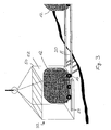
- FIG. 2 shows an embodiment of the energy system, wherein the upper storing unit 16 is arranged near the top of a hill or mountain 100.
- Loading unit 30, which, in the embodiment shown in figure 2 comprises two lifters 40, 42, lifts weights 12 during a first period from the lower storing unit 14 (not shown in figure 2 ) up to the second storing unit 16, more particularly, to the first end 26 of guiding track 20 of the second, upper storing unit 16. From said first end 26 the weights 12 will move towards the second end 28, which is arranged at the slightly lower level in comparison to the first end 26.
- the loading unit 30 can then collect weights 12 from the second end 28 and lower those weights back to the first storing unit 14 during a second period.
- FIG. 3 shows details of the loading stage 32.
- Loading stage 32 comprises a cabin 50 having an opening 52 facing the storing units 14, 16 during raising and lowering operations.
- a stage guiding track 54 is arranged at the bottom and on the inside of cabin 50. Said stage guiding track forms an extension of the guiding tracks 18, 20 of the lower and upper storing units 14, 16, respectively, when said cabin 50 is substantially aligned with either end of a guiding track 18, 20. In this aligned state, weight 12 having wheels 13 can be readily transferred between cabin 50 and the guiding tracks 18, 20.
- Figure 4 shows two upper storing units 16, 16' at the back of the edge of a mountain, wherein both guiding tracks reach the edge of the mountain 100.
Landscapes
- Engineering & Computer Science (AREA)
- Chemical & Material Sciences (AREA)
- Combustion & Propulsion (AREA)
- Mechanical Engineering (AREA)
- General Engineering & Computer Science (AREA)
- Charge And Discharge Circuits For Batteries Or The Like (AREA)
- Warehouses Or Storage Devices (AREA)
Claims (9)
- Système de stockage d'énergie comprenant une pluralité de poids (12) ; une première unité de stockage (14) et une seconde unité de stockage (16), dans lequel la première unité de stockage (14) est agencée au-dessous de la seconde unité de stockage (16) et chacune des unités de stockage (14, 16) comprend un rail de guidage (18, 20) sur lequel des poids (12) peuvent être placés et le long desquels des poids (12) peuvent être déplacés,
caractérisé en ce que :chacun desdits rails de guidage (18, 20) comprend une première partie (22, 26) et une seconde partie (24, 28), dans lequel la seconde partie (24, 28) est agencée au-dessous de la première partie (22, 26) ; et une unité de chargement (30) configurée pour lever au moins un poids (12) de la première unité de stockage (14) à la seconde unité de stockage (16) pendant une première période, convertissant ainsi l'énergie électrique en énergie potentielle, ladite unité de chargement (30) étant en outre configurée pour abaisser au moins un poids (12) de la seconde unité de stockage (16) à la première unité de stockage (14) pendant une seconde période, convertissant ainsi l'énergie potentielle en énergie électrique, dans lequel l'unité de chargement (30) est configurée pour collecter un poids (12) de la seconde partie (24) de la première unité de stockage (14) et pour placer ledit poids sur la première partie (26) de la seconde unité de stockage (16) pendant la première période et pour collecter un poids (12) de la seconde partie (28) de la seconde unité de stockage (16) et pour placer ledit poids (12) sur la première partie (22) de la première unité de stockage (14) pendant la seconde période. - Système de stockage d'énergie selon la revendication 1, dans lequel chaque poids (12) comprend des moyens tels que des roues (13), configurés pour permettre audit poids de se déplacer librement le long du rail de guidage (18, 20) sur lequel ledit poids est placé, de la première partie (22, 26) à la seconde partie (24, 28) dudit rail de guidage (18, 20).
- Système de stockage d'énergie selon l'une quelconque des revendications précédentes, dans lequel l'unité de chargement (30) comprend un étage de chargement (32) ayant un rail de guidage d'étage (54) configuré pour coopérer avec le rail de guidage (18, 20) respectif de l'une quelconque des unités de stockage (14, 16) afin de faciliter le transfert d'un poids entre l'étage de chargement (30) et le rail de guidage (18, 20) respectif.
- Système de stockage d'énergie selon l'une quelconque des revendications précédentes, comprenant une multitude d'unités de stockage agencées à différentes hauteurs.
- Système de stockage d'énergie selon l'une quelconque des revendications précédentes, dans lequel la durée de la seconde période est différente de la durée de la première période.
- Procédé pour convertir l'énergie avec un système de stockage d'énergie, le système de stockage d'énergie comprenant une pluralité de poids (12), une première unité de stockage (14) et une seconde unité de stockage (16), dans lequel la première unité de stockage (14) est agencée au-dessous de la seconde unité de stockage (16) et chacune des unités de stockage (14, 16) comprend un rail de guidage (18, 20) sur lequel des poids (12) peuvent être placés et le long desquels des poids (12) peuvent être déplacés, chacun desdits rails de guidage (18, 20) comprend une première partie (22, 26) et une seconde partie (24, 28), dans lequel la seconde partie (24, 28) est agencé au-dessous de la première partie (22, 26),
caractérisé en ce qu'il comprend les étapes consistant à :lever au moins un poids (12) de la première unité de stockage (14) à la seconde unité de stockage (16) pendant une première période, convertissant ainsi l'énergie électrique en énergie potentielle ;abaisser au moins un poids (12) de la seconde unité de stockage (16) à la première unité de stockage (14) pendant une seconde période, convertissant ainsi l'énergie potentielle en énergie électrique ;collecter un poids (12) de la seconde partie (24) de la première unité de stockage (14) et pour placer ledit poids sur la première partie (26) de la seconde unité de stockage (16) pendant la première période ; etcollecter un poids (12) de la seconde partie (28) de la seconde unité de stockage (16) et pour placer ledit poids (12) sur la première partie (22) de la première unité de stockage (14) pendant la seconde période. - Procédé selon la revendication 6, dans lequel la seconde période est plus courte que la première période.
- Procédé selon l'une quelconque des revendications 6 ou 7, dans lequel la seconde période est plus longue que la première période.
- Procédé selon l'une quelconque des revendications 6 à 8, dans lequel la première période est une période d'électricité hors pointe et la seconde période est une période de pointe d'électricité.
Applications Claiming Priority (2)
| Application Number | Priority Date | Filing Date | Title |
|---|---|---|---|
| GCP20079531 | 2007-11-24 | ||
| PCT/EP2008/009948 WO2009065619A1 (fr) | 2007-11-24 | 2008-11-24 | Procédé et appareil pour stocker de l'énergie |
Publications (2)
| Publication Number | Publication Date |
|---|---|
| EP2263005A1 EP2263005A1 (fr) | 2010-12-22 |
| EP2263005B1 true EP2263005B1 (fr) | 2013-09-04 |
Family
ID=40380325
Family Applications (1)
| Application Number | Title | Priority Date | Filing Date |
|---|---|---|---|
| EP08852400.4A Active EP2263005B1 (fr) | 2007-11-24 | 2008-11-24 | Procédé et appareil pour stocker de l'énergie |
Country Status (4)
| Country | Link |
|---|---|
| US (2) | USRE49532E1 (fr) |
| EP (1) | EP2263005B1 (fr) |
| CA (1) | CA2706551C (fr) |
| WO (1) | WO2009065619A1 (fr) |
Families Citing this family (15)
| Publication number | Priority date | Publication date | Assignee | Title |
|---|---|---|---|---|
| GB0903071D0 (en) * | 2009-02-24 | 2009-04-08 | Ahmad Rahman M | Force multiplier machine |
| US20100230970A1 (en) * | 2009-03-16 | 2010-09-16 | Manouchehr Barcohen | Green Energy |
| MD20100018A2 (ro) * | 2010-02-10 | 2011-08-31 | Константин ЧИХАН | Instalaţie energetică gravitaţională |
| WO2011146780A2 (fr) * | 2010-05-20 | 2011-11-24 | Energy Cache, Inc. | Appareils et procédés pour stockage d'énergie |
| US8674541B2 (en) * | 2011-08-16 | 2014-03-18 | Advanced Rail Energy Storage, Llc | Rail based potential energy storage for utility grid ancillary services |
| TW201525283A (zh) * | 2013-12-30 | 2015-07-01 | Jun Fu Clean Energy Co Ltd | 循環發電裝置 |
| US20150330489A1 (en) * | 2015-06-05 | 2015-11-19 | Francisco Guzman | Centrifugal electric genrator apparatus |
| US20190154009A1 (en) * | 2016-05-13 | 2019-05-23 | Imushroom Digital Limited | Recirculating gradient power system |
| CA3105981A1 (fr) | 2018-07-19 | 2020-01-23 | Energy Vault, Inc. | Systeme et procede de stockage d'energie |
| WO2020040717A1 (fr) * | 2018-08-22 | 2020-02-27 | Сергей Леонтьевич ОСИПОВ | Procédé d'accumulation et de récupération d'énergie électrique |
| JP2023510820A (ja) | 2020-01-22 | 2023-03-15 | エナジー ヴォールト インコーポレイテッド | 減衰自己センタリング機構 |
| CA3182575A1 (fr) | 2020-06-30 | 2022-01-06 | Andrea Pedretti | Systeme et procede de stockage et de distribution d'energie |
| AU2022216207A1 (en) | 2021-02-02 | 2023-08-17 | Energy Vault, Inc. | Energy storage system with elevator lift system |
| CN116262588A (zh) | 2021-12-13 | 2023-06-16 | 能源库公司 | 能量储存和输送系统及方法 |
| US20240140494A1 (en) | 2023-04-10 | 2024-05-02 | Energy Vault, Inc. | Energy storage and delivery system and method |
Family Cites Families (14)
| Publication number | Priority date | Publication date | Assignee | Title |
|---|---|---|---|---|
| GB224807A (en) | 1924-04-14 | 1924-11-20 | Mary Jane Aikenhead Davy | Improvements in fasteners or retainers for shoulder straps of underwear |
| US3953971A (en) * | 1975-01-02 | 1976-05-04 | Parker Sidney A | Power generation arrangement |
| GB2090939B (en) * | 1981-01-10 | 1984-07-18 | Marquez Andrew | Power generating apparatus |
| GB8823224D0 (en) * | 1988-10-04 | 1988-11-09 | Hare J J | Electricity generating system |
| JPH06147097A (ja) * | 1992-11-09 | 1994-05-27 | Yoneda Seisakusho:Yugen | 重力応用発電装置 |
| US5873249A (en) | 1997-07-03 | 1999-02-23 | Alkhamis; Mohammed | Energy generating system using differential elevation |
| US6009707A (en) * | 1998-01-21 | 2000-01-04 | Alkhamis; Mohammed | Buoyancy driven energy producing device |
| US6249057B1 (en) * | 1999-10-20 | 2001-06-19 | Daniel Lehet | Hydrodynamic energy conversion apparatus |
| DE10037678A1 (de) | 2000-07-28 | 2002-02-14 | Mathieu Ernst Ulrich | Mechanisches Hubspeicherwerk |
| WO2002076782A2 (fr) * | 2001-03-26 | 2002-10-03 | James Russell Powell | Stockage et distribution de courant electrique a l'aide d'une technique de levitation magnetique |
| DE202004011770U1 (de) * | 2004-07-28 | 2004-09-30 | Brüggemann, Bernhard W. | Energiespeichervorrichtung |
| FI117938B (fi) * | 2005-10-07 | 2007-04-30 | Kone Corp | Hissijärjestelmä |
| US7854119B2 (en) * | 2007-07-07 | 2010-12-21 | David Joseph Strain | Hydroelectric device |
| CN101392737A (zh) * | 2007-09-21 | 2009-03-25 | 高琪 | “电梯”发电 |
-
2008
- 2008-11-24 EP EP08852400.4A patent/EP2263005B1/fr active Active
- 2008-11-24 US US14/461,239 patent/USRE49532E1/en active Active
- 2008-11-24 US US12/744,447 patent/US8358020B2/en not_active Ceased
- 2008-11-24 CA CA2706551A patent/CA2706551C/fr active Active
- 2008-11-24 WO PCT/EP2008/009948 patent/WO2009065619A1/fr active Application Filing
Also Published As
| Publication number | Publication date |
|---|---|
| CA2706551A1 (fr) | 2009-05-28 |
| WO2009065619A1 (fr) | 2009-05-28 |
| USRE49532E1 (en) | 2023-05-16 |
| EP2263005A1 (fr) | 2010-12-22 |
| US20100301616A1 (en) | 2010-12-02 |
| CA2706551C (fr) | 2016-10-04 |
| US8358020B2 (en) | 2013-01-22 |
Similar Documents
| Publication | Publication Date | Title |
|---|---|---|
| EP2263005B1 (fr) | Procédé et appareil pour stocker de l'énergie | |
| WO2015078098A1 (fr) | Système de génération d'électricité au moyen de l'énergie potentielle de poids | |
| US11920569B2 (en) | Energy storage and delivery system with an elevator lift system and method of operating the same | |
| MX2012001750A (es) | Sistema de almacenamiento de energia electrica a escala de servicio publico. | |
| CN206283454U (zh) | 一种新能源汽车太阳能板调节装置 | |
| CN207382232U (zh) | 一种具有自动调节和清洗功能的太阳能发电装置 | |
| CN104579122A (zh) | 提斗式流沙储能光伏发电系统 | |
| CN104682832A (zh) | 一种野外营区能源供给系统 | |
| CN103498762B (zh) | 机械储能风力发电系统 | |
| CN107661610A (zh) | 一种网球拾捡遥控车及使用方法 | |
| CN204206064U (zh) | 一种野外模块化能源供给系统 | |
| CN207820528U (zh) | 带有电动机的移栽机 | |
| WO2015078097A1 (fr) | Système pour préparer de l'air comprimé à l'aide de l'énergie potentielle d'un poids | |
| CN109586657A (zh) | 一种具有自动调节和清洗功能的太阳能发电装置 | |
| CN201349161Y (zh) | 一种再生能源式家用发电装置 | |
| CN206921938U (zh) | 一种新能源汽车电池组 | |
| CN210516929U (zh) | 太阳能充电型铅蓄电池 | |
| CN202628399U (zh) | 一种可以储存风能输出电压平稳直接上网的风力发电机 | |
| CN207867598U (zh) | 一种自动柜员机纸币的抬升结构 | |
| CN107310451A (zh) | 一种电力配电运维一体化移动工作平台 | |
| CN107681971A (zh) | 太阳能光伏板过桥自动升降架及光伏电站 | |
| CN205814071U (zh) | 可自发电摇篮 | |
| CN207579842U (zh) | 一种电瓶牵引车电池组更换装置 | |
| CN203840269U (zh) | 太阳能自动跟踪系统 | |
| CN105048954A (zh) | 一种盐碱地用便携式自动调节的太阳能供电装置 |
Legal Events
| Date | Code | Title | Description |
|---|---|---|---|
| PUAI | Public reference made under article 153(3) epc to a published international application that has entered the european phase |
Free format text: ORIGINAL CODE: 0009012 |
|
| 17P | Request for examination filed |
Effective date: 20100617 |
|
| AK | Designated contracting states |
Kind code of ref document: A1 Designated state(s): AT BE BG CH CY CZ DE DK EE ES FI FR GB GR HR HU IE IS IT LI LT LU LV MC MT NL NO PL PT RO SE SI SK TR |
|
| AX | Request for extension of the european patent |
Extension state: AL BA MK RS |
|
| DAX | Request for extension of the european patent (deleted) | ||
| RAP1 | Party data changed (applicant data changed or rights of an application transferred) |
Owner name: KING SAUD UNIVERSITY |
|
| RIN1 | Information on inventor provided before grant (corrected) |
Inventor name: AL-KHAMIS, MOHAMMED ABDULAZIZ |
|
| GRAP | Despatch of communication of intention to grant a patent |
Free format text: ORIGINAL CODE: EPIDOSNIGR1 |
|
| INTG | Intention to grant announced |
Effective date: 20130430 |
|
| GRAS | Grant fee paid |
Free format text: ORIGINAL CODE: EPIDOSNIGR3 |
|
| GRAA | (expected) grant |
Free format text: ORIGINAL CODE: 0009210 |
|
| AK | Designated contracting states |
Kind code of ref document: B1 Designated state(s): AT BE BG CH CY CZ DE DK EE ES FI FR GB GR HR HU IE IS IT LI LT LU LV MC MT NL NO PL PT RO SE SI SK TR |
|
| REG | Reference to a national code |
Ref country code: GB Ref legal event code: FG4D |
|
| REG | Reference to a national code |
Ref country code: CH Ref legal event code: EP |
|
| REG | Reference to a national code |
Ref country code: AT Ref legal event code: REF Ref document number: 630689 Country of ref document: AT Kind code of ref document: T Effective date: 20130915 |
|
| REG | Reference to a national code |
Ref country code: IE Ref legal event code: FG4D |
|
| REG | Reference to a national code |
Ref country code: DE Ref legal event code: R096 Ref document number: 602008027378 Country of ref document: DE Effective date: 20131031 |
|
| REG | Reference to a national code |
Ref country code: AT Ref legal event code: MK05 Ref document number: 630689 Country of ref document: AT Kind code of ref document: T Effective date: 20130904 |
|
| REG | Reference to a national code |
Ref country code: NL Ref legal event code: VDEP Effective date: 20130904 |
|
| PG25 | Lapsed in a contracting state [announced via postgrant information from national office to epo] |
Ref country code: HR Free format text: LAPSE BECAUSE OF FAILURE TO SUBMIT A TRANSLATION OF THE DESCRIPTION OR TO PAY THE FEE WITHIN THE PRESCRIBED TIME-LIMIT Effective date: 20130904 Ref country code: NO Free format text: LAPSE BECAUSE OF FAILURE TO SUBMIT A TRANSLATION OF THE DESCRIPTION OR TO PAY THE FEE WITHIN THE PRESCRIBED TIME-LIMIT Effective date: 20131204 Ref country code: SE Free format text: LAPSE BECAUSE OF FAILURE TO SUBMIT A TRANSLATION OF THE DESCRIPTION OR TO PAY THE FEE WITHIN THE PRESCRIBED TIME-LIMIT Effective date: 20130904 Ref country code: AT Free format text: LAPSE BECAUSE OF FAILURE TO SUBMIT A TRANSLATION OF THE DESCRIPTION OR TO PAY THE FEE WITHIN THE PRESCRIBED TIME-LIMIT Effective date: 20130904 Ref country code: CY Free format text: LAPSE BECAUSE OF FAILURE TO SUBMIT A TRANSLATION OF THE DESCRIPTION OR TO PAY THE FEE WITHIN THE PRESCRIBED TIME-LIMIT Effective date: 20130911 Ref country code: LT Free format text: LAPSE BECAUSE OF FAILURE TO SUBMIT A TRANSLATION OF THE DESCRIPTION OR TO PAY THE FEE WITHIN THE PRESCRIBED TIME-LIMIT Effective date: 20130904 |
|
| REG | Reference to a national code |
Ref country code: NL Ref legal event code: VDEP Effective date: 20130904 |
|
| REG | Reference to a national code |
Ref country code: LT Ref legal event code: MG4D |
|
| PG25 | Lapsed in a contracting state [announced via postgrant information from national office to epo] |
Ref country code: GR Free format text: LAPSE BECAUSE OF FAILURE TO SUBMIT A TRANSLATION OF THE DESCRIPTION OR TO PAY THE FEE WITHIN THE PRESCRIBED TIME-LIMIT Effective date: 20131205 Ref country code: FI Free format text: LAPSE BECAUSE OF FAILURE TO SUBMIT A TRANSLATION OF THE DESCRIPTION OR TO PAY THE FEE WITHIN THE PRESCRIBED TIME-LIMIT Effective date: 20130904 Ref country code: PL Free format text: LAPSE BECAUSE OF FAILURE TO SUBMIT A TRANSLATION OF THE DESCRIPTION OR TO PAY THE FEE WITHIN THE PRESCRIBED TIME-LIMIT Effective date: 20130904 Ref country code: LV Free format text: LAPSE BECAUSE OF FAILURE TO SUBMIT A TRANSLATION OF THE DESCRIPTION OR TO PAY THE FEE WITHIN THE PRESCRIBED TIME-LIMIT Effective date: 20130904 Ref country code: SI Free format text: LAPSE BECAUSE OF FAILURE TO SUBMIT A TRANSLATION OF THE DESCRIPTION OR TO PAY THE FEE WITHIN THE PRESCRIBED TIME-LIMIT Effective date: 20130904 |
|
| PG25 | Lapsed in a contracting state [announced via postgrant information from national office to epo] |
Ref country code: CY Free format text: LAPSE BECAUSE OF FAILURE TO SUBMIT A TRANSLATION OF THE DESCRIPTION OR TO PAY THE FEE WITHIN THE PRESCRIBED TIME-LIMIT Effective date: 20130904 Ref country code: BE Free format text: LAPSE BECAUSE OF FAILURE TO SUBMIT A TRANSLATION OF THE DESCRIPTION OR TO PAY THE FEE WITHIN THE PRESCRIBED TIME-LIMIT Effective date: 20130904 |
|
| PG25 | Lapsed in a contracting state [announced via postgrant information from national office to epo] |
Ref country code: SK Free format text: LAPSE BECAUSE OF FAILURE TO SUBMIT A TRANSLATION OF THE DESCRIPTION OR TO PAY THE FEE WITHIN THE PRESCRIBED TIME-LIMIT Effective date: 20130904 Ref country code: IS Free format text: LAPSE BECAUSE OF FAILURE TO SUBMIT A TRANSLATION OF THE DESCRIPTION OR TO PAY THE FEE WITHIN THE PRESCRIBED TIME-LIMIT Effective date: 20140104 Ref country code: RO Free format text: LAPSE BECAUSE OF FAILURE TO SUBMIT A TRANSLATION OF THE DESCRIPTION OR TO PAY THE FEE WITHIN THE PRESCRIBED TIME-LIMIT Effective date: 20130904 Ref country code: NL Free format text: LAPSE BECAUSE OF FAILURE TO SUBMIT A TRANSLATION OF THE DESCRIPTION OR TO PAY THE FEE WITHIN THE PRESCRIBED TIME-LIMIT Effective date: 20130904 Ref country code: EE Free format text: LAPSE BECAUSE OF FAILURE TO SUBMIT A TRANSLATION OF THE DESCRIPTION OR TO PAY THE FEE WITHIN THE PRESCRIBED TIME-LIMIT Effective date: 20130904 |
|
| PG25 | Lapsed in a contracting state [announced via postgrant information from national office to epo] |
Ref country code: ES Free format text: LAPSE BECAUSE OF FAILURE TO SUBMIT A TRANSLATION OF THE DESCRIPTION OR TO PAY THE FEE WITHIN THE PRESCRIBED TIME-LIMIT Effective date: 20130904 |
|
| REG | Reference to a national code |
Ref country code: DE Ref legal event code: R097 Ref document number: 602008027378 Country of ref document: DE |
|
| PG25 | Lapsed in a contracting state [announced via postgrant information from national office to epo] |
Ref country code: PT Free format text: LAPSE BECAUSE OF FAILURE TO SUBMIT A TRANSLATION OF THE DESCRIPTION OR TO PAY THE FEE WITHIN THE PRESCRIBED TIME-LIMIT Effective date: 20140106 |
|
| REG | Reference to a national code |
Ref country code: CH Ref legal event code: PL |
|
| PLBE | No opposition filed within time limit |
Free format text: ORIGINAL CODE: 0009261 |
|
| STAA | Information on the status of an ep patent application or granted ep patent |
Free format text: STATUS: NO OPPOSITION FILED WITHIN TIME LIMIT |
|
| PG25 | Lapsed in a contracting state [announced via postgrant information from national office to epo] |
Ref country code: CH Free format text: LAPSE BECAUSE OF NON-PAYMENT OF DUE FEES Effective date: 20131130 Ref country code: MC Free format text: LAPSE BECAUSE OF FAILURE TO SUBMIT A TRANSLATION OF THE DESCRIPTION OR TO PAY THE FEE WITHIN THE PRESCRIBED TIME-LIMIT Effective date: 20130904 Ref country code: LI Free format text: LAPSE BECAUSE OF NON-PAYMENT OF DUE FEES Effective date: 20131130 |
|
| 26N | No opposition filed |
Effective date: 20140605 |
|
| REG | Reference to a national code |
Ref country code: IE Ref legal event code: MM4A |
|
| PG25 | Lapsed in a contracting state [announced via postgrant information from national office to epo] |
Ref country code: IT Free format text: LAPSE BECAUSE OF FAILURE TO SUBMIT A TRANSLATION OF THE DESCRIPTION OR TO PAY THE FEE WITHIN THE PRESCRIBED TIME-LIMIT Effective date: 20130904 |
|
| REG | Reference to a national code |
Ref country code: DE Ref legal event code: R097 Ref document number: 602008027378 Country of ref document: DE Effective date: 20140605 |
|
| PG25 | Lapsed in a contracting state [announced via postgrant information from national office to epo] |
Ref country code: DK Free format text: LAPSE BECAUSE OF FAILURE TO SUBMIT A TRANSLATION OF THE DESCRIPTION OR TO PAY THE FEE WITHIN THE PRESCRIBED TIME-LIMIT Effective date: 20130904 |
|
| PG25 | Lapsed in a contracting state [announced via postgrant information from national office to epo] |
Ref country code: IE Free format text: LAPSE BECAUSE OF NON-PAYMENT OF DUE FEES Effective date: 20131124 |
|
| PG25 | Lapsed in a contracting state [announced via postgrant information from national office to epo] |
Ref country code: CZ Free format text: LAPSE BECAUSE OF FAILURE TO SUBMIT A TRANSLATION OF THE DESCRIPTION OR TO PAY THE FEE WITHIN THE PRESCRIBED TIME-LIMIT Effective date: 20130904 |
|
| PG25 | Lapsed in a contracting state [announced via postgrant information from national office to epo] |
Ref country code: TR Free format text: LAPSE BECAUSE OF FAILURE TO SUBMIT A TRANSLATION OF THE DESCRIPTION OR TO PAY THE FEE WITHIN THE PRESCRIBED TIME-LIMIT Effective date: 20130904 |
|
| PG25 | Lapsed in a contracting state [announced via postgrant information from national office to epo] |
Ref country code: LU Free format text: LAPSE BECAUSE OF NON-PAYMENT OF DUE FEES Effective date: 20131124 Ref country code: BG Free format text: LAPSE BECAUSE OF FAILURE TO SUBMIT A TRANSLATION OF THE DESCRIPTION OR TO PAY THE FEE WITHIN THE PRESCRIBED TIME-LIMIT Effective date: 20130904 Ref country code: HU Free format text: LAPSE BECAUSE OF FAILURE TO SUBMIT A TRANSLATION OF THE DESCRIPTION OR TO PAY THE FEE WITHIN THE PRESCRIBED TIME-LIMIT; INVALID AB INITIO Effective date: 20081124 |
|
| PG25 | Lapsed in a contracting state [announced via postgrant information from national office to epo] |
Ref country code: MT Free format text: LAPSE BECAUSE OF FAILURE TO SUBMIT A TRANSLATION OF THE DESCRIPTION OR TO PAY THE FEE WITHIN THE PRESCRIBED TIME-LIMIT Effective date: 20130904 |
|
| REG | Reference to a national code |
Ref country code: FR Ref legal event code: PLFP Year of fee payment: 8 |
|
| REG | Reference to a national code |
Ref country code: FR Ref legal event code: PLFP Year of fee payment: 9 |
|
| REG | Reference to a national code |
Ref country code: FR Ref legal event code: PLFP Year of fee payment: 10 |
|
| PGFP | Annual fee paid to national office [announced via postgrant information from national office to epo] |
Ref country code: GB Payment date: 20221229 Year of fee payment: 15 Ref country code: FR Payment date: 20221229 Year of fee payment: 15 |
|
| PGFP | Annual fee paid to national office [announced via postgrant information from national office to epo] |
Ref country code: DE Payment date: 20221230 Year of fee payment: 15 |