EP2261765A2 - Elektrischer Schalter - Google Patents
Elektrischer Schalter Download PDFInfo
- Publication number
- EP2261765A2 EP2261765A2 EP10006030A EP10006030A EP2261765A2 EP 2261765 A2 EP2261765 A2 EP 2261765A2 EP 10006030 A EP10006030 A EP 10006030A EP 10006030 A EP10006030 A EP 10006030A EP 2261765 A2 EP2261765 A2 EP 2261765A2
- Authority
- EP
- European Patent Office
- Prior art keywords
- lever
- actuating member
- switching
- pivoting
- switch according
- Prior art date
- Legal status (The legal status is an assumption and is not a legal conclusion. Google has not performed a legal analysis and makes no representation as to the accuracy of the status listed.)
- Granted
Links
Images



Classifications
-
- G—PHYSICS
- G05—CONTROLLING; REGULATING
- G05G—CONTROL DEVICES OR SYSTEMS INSOFAR AS CHARACTERISED BY MECHANICAL FEATURES ONLY
- G05G9/00—Manually-actuated control mechanisms provided with one single controlling member co-operating with two or more controlled members, e.g. selectively, simultaneously
- G05G9/02—Manually-actuated control mechanisms provided with one single controlling member co-operating with two or more controlled members, e.g. selectively, simultaneously the controlling member being movable in different independent ways, movement in each individual way actuating one controlled member only
- G05G9/04—Manually-actuated control mechanisms provided with one single controlling member co-operating with two or more controlled members, e.g. selectively, simultaneously the controlling member being movable in different independent ways, movement in each individual way actuating one controlled member only in which movement in two or more ways can occur simultaneously
- G05G9/047—Manually-actuated control mechanisms provided with one single controlling member co-operating with two or more controlled members, e.g. selectively, simultaneously the controlling member being movable in different independent ways, movement in each individual way actuating one controlled member only in which movement in two or more ways can occur simultaneously the controlling member being movable by hand about orthogonal axes, e.g. joysticks
-
- G—PHYSICS
- G05—CONTROLLING; REGULATING
- G05G—CONTROL DEVICES OR SYSTEMS INSOFAR AS CHARACTERISED BY MECHANICAL FEATURES ONLY
- G05G9/00—Manually-actuated control mechanisms provided with one single controlling member co-operating with two or more controlled members, e.g. selectively, simultaneously
- G05G9/02—Manually-actuated control mechanisms provided with one single controlling member co-operating with two or more controlled members, e.g. selectively, simultaneously the controlling member being movable in different independent ways, movement in each individual way actuating one controlled member only
- G05G9/04—Manually-actuated control mechanisms provided with one single controlling member co-operating with two or more controlled members, e.g. selectively, simultaneously the controlling member being movable in different independent ways, movement in each individual way actuating one controlled member only in which movement in two or more ways can occur simultaneously
- G05G9/047—Manually-actuated control mechanisms provided with one single controlling member co-operating with two or more controlled members, e.g. selectively, simultaneously the controlling member being movable in different independent ways, movement in each individual way actuating one controlled member only in which movement in two or more ways can occur simultaneously the controlling member being movable by hand about orthogonal axes, e.g. joysticks
- G05G2009/0474—Manually-actuated control mechanisms provided with one single controlling member co-operating with two or more controlled members, e.g. selectively, simultaneously the controlling member being movable in different independent ways, movement in each individual way actuating one controlled member only in which movement in two or more ways can occur simultaneously the controlling member being movable by hand about orthogonal axes, e.g. joysticks characterised by means converting mechanical movement into electric signals
Definitions
- the invention relates to an electrical switch according to the preamble of patent claim 1 or 3.
- Electrical switches formed in the manner of a joystick and / or cursor switch and / or in the manner of a turntable serve to input data for an electrical appliance by a user.
- switches are used for car radios, navigation devices, on-board computers or search for controlling other functions in motor vehicles.
- an electrical switch can also be used as a multi-function switch for menu control of functions via a display in the motor vehicle.
- Such an electrical switch is from the US-A-4,459,440 known and has a movable in a pivot plane mounted actuator.
- the actuating member cooperates with a pivoting means such that the actuating member is pivotable in the pivoting plane in at least one direction from a neutral position in a pivot position assigned to this direction by the user.
- the pivoting position is formed as a switching position, such that the actuating member in the switching position acts on a switching element switching.
- the actuator acts directly on the electrical switch designed as a switching element, whereby the switching position of this switch, especially with regard to a large-scale production, is very sensitive to tolerances. Furthermore, the known switch gives no indication of the realization of ergonomic requirements, in particular those which are desirable for use in motor vehicles. Finally, it is also not clear whether this switch is suitable for use in a motor vehicle with tight installation spaces.
- This switch has a movable actuator.
- the actuator cooperates with a rotating means such that the actuating member is rotatable by at least one angle from an initial position in at least one rotational position.
- the rotary position is formed as a display position, in which the actuating member acts on a switching element, sensor element, signal element o. The like. Actuating or switching.
- the invention has for its object to further develop the switch so that the tolerance sensitivity between the actuator and the switching element is reduced.
- the actuator of the switch should be adjustable in several directions, with a secure sensing of several, for example 8 directions should be ensured with respect to a stable segment size of the individual segments for the Verschwenknchtungen.
- the switch should also be further developed such that the actuator is rotatable by a predetermined angle.
- a stop for the Drehfunkion clockwise and / or counterclockwise to be created should include a variable angle, which is specified by an external control signal.
- the actuator cooperates with a lever such that the pivotal movement of the actuator is converted into a translated rotational movement of the lever.
- the switching element switching.
- even small Schwmkambaen be converted into sufficiently large actuation paths for the switching element, which reduces the sensitivity to tolerances.
- the actuating member in particular via the rotating means, coupled to an incremental ring.
- a movable by means of an adjusting element latch is engageable with at least one window on the increment ring, so that the bolt constitutes a stop for the rotational function.
- the invention thus provides a central control element (ZBE) with adjustable stops, which are flexibly adaptable to the respective requirements in the motor vehicle in a simple manner.
- the actuating member can additionally be designed to be rotatable and / or pivotable.
- the actuating member cooperates with a rotating means such that the actuating member is rotatable by at least one angle from an initial position into at least one rotational position formed as a switching position with a switching element.
- the actuating member cooperates with a pivoting means such that the actuating member is pivotable in a pivoting plane in at least one direction from a neutral position into a pivoting position.
- the pivot position is designed as a switching position, so that the switch generates a corresponding switching signal when the actuator is given.
- the functionality of the switch can finally be further increased when the actuator cooperates with a displacement means such that the actuator at least one distance from a Zero position in a displacement position is linearly movable.
- the displacement position is formed as a switching element having a switching position, whereby the actuator allows a kind of "Enter" operation.
- a switching flag can be arranged on the lever, wherein the switching flag in the pivot position, the switching element actuates switching.
- the switching element may consist of a sensor. In functionally reliable manner, in particular for use in motor vehicles, the sensor can then consist of an actuatable by the switching flag photocell.
- the pivoting means comprises a pivotally mounted at one end and arranged at the other end on the actuating rod joint rod.
- the lever may be rotatably arranged in a plane which is approximately perpendicular to the articulated rod in the neutral position.
- the lever can be configured as a one-armed lever, wherein the axis of rotation of the lever is located at one end thereof.
- the switching lug is arranged at the other end of the lever, in particular approximately perpendicularly projecting from the lever.
- the hinge rod can pass through a recess which is located approximately centrally between the two ends of the lever, for rotation of the lever upon pivoting of the actuating member.
- the pivoting means comprises a universal joint for the pivotable mounting of the one end of the articulated rod.
- a further, second lever in approximately crosswise to the first lever, in particular substantially in the plane extending approximately perpendicular to the articulated rod in the neutral position, be arranged.
- the actuating member with the articulated rod actuates two, in particular geometrically differently configured, levers with switching lugs for the light barriers.
- the first lever for the actuation of the photoelectric barrier during pivoting in north / south direction and the second lever for the actuation of the photoelectric sensors during pivoting in east / west direction serve.
- the functionality of the switch can thereby increase that the operation of the photoelectric sensors when pivoting in Intermediate directions resulting from a combination of the rotational positions of the first lever and the second lever In such a configuration advantageously minimizes the translation of small Betat Trentswege in large switching paths by means of lever arrangement scattering of the segment sizes by position deviations to the desired position of the sensors designed as light barriers.
- the two motion translation levers of the actuator and the sensors configured as light barriers can be arranged in two mutually parallel planes which extend in the x-y direction.
- Such an arrangement results in a simple yet compact design. It makes sense that the plane for the sensors is formed by a printed circuit board.
- the rotating means comprises a rotatably mounted at one end and arranged at the other end on the actuator shaft.
- the shaft is arranged in the articulated rod.
- a rotary ring may be located at one end of the shaft.
- the increment ring can be movable by means of a toothing of the rotating means, in particular of the rotary ring.
- the switching element a photocell. Teeth can be arranged on the increment ring, so that the pulses are generated by the light barrier by interaction of the teeth with the light barrier upon rotation of the increment ring.
- the incremental ring may cooperate with at least one spring-loaded ball for generating mechanical rotational locking positions.
- a locking at any position depending on the detent by a control signal allows. For example, 24 notches per revolution may be present, the locking takes place in each case in the locking position 12.
- the solenoid can have two stable end positions.
- the bolt is movable by brief energization of the solenoid.
- the latch is arranged on a lever.
- the lever may be configured like a fork, wherein the latch is located at one end of the lever and the other end of the lever is articulated to a plunger of the solenoid. Furthermore, the plunger is located on the side facing away from the increment of the lifting magnet, such that the fork-like lever engages around the lifting magnet.
- a central control element (ZBE) with a detection of 8 operating directions.
- a rotary knob with a shaft and a joint rod actuates two geometrically different levers with switching lugs for the sensors designed as light barriers.
- the first lever is for north / south operation.
- the second lever is for east / west operation.
- the intermediate directions result from the combination of the positions of the first lever and the second lever.
- the lever transmitter set and the sensors designed as light barriers are arranged in one plane, namely the xy plane.
- the translation of the small actuation paths in large switching paths minimizes scattering of the segment sizes due to position deviations from the nominal position of the sensors designed as light barriers.
- the switch has a knob, wherein the rotational movement of the knob is guided via a shaft down and with a pair of gears from the axis of rotation and translated.
- the mechanical ball catch for example, for 24 notches per revolution, forms a unit with the torque overload protection and increment ring with window for the bolt, which includes only a small tolerance chain.
- the signal detection takes place, for example, via switching lugs on the increment ring and a light barrier with 2 light curtains for detecting the direction of rotation.
- the actuator consisting of solenoids, the power levels for controlling the solenoids and the signal detection by the light barrier are arranged on a printed circuit board.
- the advantages achieved by the invention are in particular that the example designed as a solenoid actuator does not require continuous power but has two stable end positions.
- the change of these end positions by brief Bestromungs committee results in a low electrical consumption for the stop function in the ZBE, especially in comparison to the previously conventional motor brake.
- the switch manages in spite of high functionality with little space.
- the switch for tight spaces as given in the dashboard, the center console, the armrest o. The like. In the vehicle are suitable.
- the switch is error-prone and has a long service life.
- the switch according to the invention can thus be used advantageously in harsh environmental conditions, for example in motor vehicles.
- the switch has a good feel, for example, the switch has eight preferential directions for the actuator at low actuation paths, which contributes to increasing the ergonomics.
- high functionality of the switch is easy to operate, for example, with the fingers of one hand, with incorrect operations are largely excluded.
- the switch is inexpensive to manufacture.
- Fig. 1 is an inventive electrical switch 1 to see, which is designed in the manner of a joystick and / or cursor switch or multi-function switch.
- the switch 1 has an actuator 2, which is manually movable by the user in several different ways.
- the actuator 2 acts with pivoting means 3 together so that the actuator 2 is pivotable in a pivoting plane in at least one direction in the manner of a preferred direction by the user from a neutral position to a pivot position.
- the actuator 2 cooperates with Verachiebeschn 5 such that the actuator 2 is linearly movable by at least a distance from a zero position in a displacement position by pressing the user in the manner of an "Eater” function.
- the actuator 2 still works with in Fig.
- the pivot position, the Verschiobeatellung and the rotational position are each formed as a switching position, such that the actuator 2 in the respective switching position on an associated switching element 6, 24, 35 (see this search Fig. 4 ), Sensor element, signal element o. The like. Acting switching.
- the switching element 35 for the displacement position consists of a switching mat, which offers a certain feel to the user when pressing the actuator 2.
- the switch 1 has a housing 7, which in turn consists of an upper housing part 7 'and a lower housing part 7 "protrudes from the housing 7, namely on the upper housing part 7', the Eatauerseorgan 2 for operation by the user
- Actuator 2 comprises a knob 9, wherein the knob 9 at one end of a link rod 8 and a shaft 20 (see Fig. 4
- the pivoting means 3, the Verschicbesch 5 and / or the rotating means 4 are based on the mounted in the housing 7 articulated rod 8 with the shaft 20.
- the pivoting means 3 as can be seen from Fig.
- the actuator 2 acts by means of the hinge rod 8 with the lever 10 such that the pivotal movement of the actuator 2 is converted into a translated rotational movement of the lever 10, the lever 10 is a further Switch lug 12 is arranged so that the switching lug 12 actuates the switching element 6 in the pivoting position switching.
- the switching element 6 consists of a sensor, namely an actuatable by the switching flag 12, fork-like light barrier 6, which is located on a housing 7 located in the x- / y-direction extending parallel to the plane 14 circuit board 17.
- the lever 10 is rotatably mounted in the plane 14 which is approximately perpendicular to the articulated rod 8 in the neutral position.
- the lever 10 is designed as a one-armed lever, wherein the axis of rotation 15 of the lever 10 is located at one end thereof.
- the switching lug 12 is at the other end of the lever 10, in approximately perpendicularly projecting from the lever 10, respectively.
- the pivot rod 8 passes through a recess 16 which is located approximately centrally between the two ends of the lever 10, for rotation of the lever 10 upon pivoting of the rotary knob.
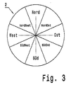
- the actuator 2 is not only in one direction but in the manner of a wind rose according to the Fig. 3 in multiple directions, in eight, with the cardinal directions directions, pivotally configured by the hinge rod 8 is mounted in a universal joint 18 in the housing 7 and with a direction defining, and the pivoting feel for the user generating pivoting gate 19 cooperates, which in Fig. 1 you can see.
- further light barriers 6 ' are arranged on the printed circuit board 17.
- another, second lever 11 is arranged with a switching lug 13 in approximately crosswise to the first lever 10 substantially in the plane 14, such that the knob 9 during pivoting by means of the pivot rod 8 with the shaft 20 disposed therein these two geometrically differently accessiblestalteteten Lever 10,11 with switching lugs 12, 13 for the photoelectric sensors 6,6 'actuated.
- the first lever 10 serves for the actuation of the light barriers 6 when pivoting in north / south direction and the second lever 11 for the actuation of the light barriers 6 'when pivoting in east / west direction.
- the actuation of the light barriers 6, 6 'when pivoting in intermediate directions resulting from a combination of the rotational positions of the first lever 10 and the second lever eleventh
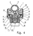
- the Betquestioned Trentalistsorsan 2 is designed to be rotatable. How to get in Fig. 4 sees the rotation means 4 for the knob 9, the shaft 20 and a rotary ring 21.
- the actuator 2 is further coupled via the rotating means 4 with an increment ring 22 by the increment ring 22 is movable by means of acting as a gear toothing 23 of the rotating means 4 ,
- the switching element 24 for detecting the rotation of the rotary knob 9 consists of a fork-shaped light barrier.
- teeth 25 are arranged, which are movable through the bifurcated light barrier 24 therethrough, so that pulses are generated by the photocell 24 upon rotation of the increment ring 22.
- spring-loaded ball which in corresponding, in Fig. 5 visible holes 26 engages the Incrementring 22.
- the rotational function of the actuator 2 has an adjustable stop, so that the number of Drehincremente can be limited in a variable manner.
- a movable by means of an adjusting element 27 bolt 28 in engagement with at least one, bavoraugtute a plurality of windows 29 on the increment ring 22 can be brought, so that the bolt 28 represents the stop for the rotational function.
- the adjusting element 27 may be a lifting magnet, an electric motor, a stepping motor, a piezoelectric element or the like.
- the latch 28 is disposed on a lever 30, wherein the lever 30 is configured like a fork.
- the latch 28 is located at one end of the lever 30 while the other end of the lever 30 is on a plunger 31 of the solenoid 27 is on.
- the plunger 31 is located on the side facing away from the Inkrementring 22 of the solenoid 27, such that the fork-like lever 30, the solenoid 27 in order compact arrangement in the housing 7 surrounds.
- the solenoid 27 has two stable end positions, whereby the solenoid 27 does not require continuous power, but rather the latch 28 is movable by only brief energization of the solenoid 27.
- a stop for the rotary function of the rotary knob 9 is realized in a clockwise and counterclockwise direction.
- a second second, by means of a solenoid 27 'movable latch 28' on the increment ring 22 is arranged, as can be seen from the Fig. 4 sees.
- the two bars 28, 28 'each provide a variable stop for the rotational function of the knob 9 in a clockwise and counterclockwise direction.
- the solenoid 27 is used for blocking the clockwise rotation and the solenoid 27 'for blocking the counterclockwise rotation.
- the increment ring 22 can still be a slip clutch 32 according to Fig. 5 to ensure torque overload protection when the respective stops act.
- Fig. 5 nor an electronics located on the circuit board 17 33 for controlling the solenoids 27, 27 'and a cable outlet 34 for contacting the switch 1 with, for example, a bus system to see.
- Such a multi-function switch can be used for car radios, for navigation systems and / or for control devices, displays o. The like. In motor vehicles.
- the invention is not limited to the described and illustrated embodiment. Rather, it also encompasses all expert developments within the scope of the invention defined by the claims.
- such a multi-function switch can be used advantageously as input means for computers, machine tools, household appliances o. The like.
- the invention can be used not only in the described multi-function switches but also in such switches, in which the actuator only pivoted or is designed only rotatable in the manner of a turntable.
Landscapes
- Physics & Mathematics (AREA)
- General Physics & Mathematics (AREA)
- Engineering & Computer Science (AREA)
- Automation & Control Theory (AREA)
- Switches With Compound Operations (AREA)
Abstract
Description
- Die Erfindung betrifft einen elektrischen Schalter nach dem Oberbegriff des Patentanspruchs 1 oder 3.
- In der Art eines Joystick- und/oder Cursor-Schalters und/oder in der Art eines Drehstellers ausgebildete elektrische Schalter dienen zur Eingabe von Daten für ein elektrisches Gerät durch einen Benutzer. Beispielsweise werden solche Schalter für Autoradios, Navigationsgeräte, Bordcomputer oder such zur Steuerung sonstiger Funktionen in Kraftfahrzeugen verwendet. Insbesondere läßt sich ein solcher elektrischer Schalter auch als Multirunktionsschalter zur Menüsteuerung von Funktionen über ein Display im Kraftfahrzeug verwenden.
- Ein derartiger elektrischer Schalter ist aus der
US-A-4 459 440 bekannt und besitzt ein in einer Verschwenkebene bewegbar gelagertes Betätigungsorgan. Das Betätigungsorgan wirkt mit einem Verschwenkmittel derart zusammen, daß das Betätigungsorgan in der Verschwenkebene in wenigstens eine Richtung aus einer neutralen Stellung in eine der dieser Richtung zugeordnete Schwenkstellung durch den Benutzer verschwenkbar ist. Die Schwenkstellung ist als eine Schaltstellung ausgebildet, derart daß das Betätigungsorgan in der Schaltstellung auf ein Schaltelement schaltend einwirkt. - Beim bekannten Schalter wirkt das Betätigungsorgan direkt auf das als elektrischer Schalter ausgebildete Schaltelement ein, womit die Schaltstellung dieses Schalters, vor allem auch im Hinblick auf eine Großserienfertigung, sehr toleranzempfindlich ist. Desweiteren gibt der bekannte Schalter keinen Hinweis auf die Realisierung von ergonomischen Erfordernissen, insbesondere solchen, die für den Einsatz im Kraftfahrzeug wünschenswert sind. Schließlich ist auch nicht weiter ersichtlich, ob dieser Schalter zum Einsatz in einem Kraftfahrzeug mit beengten Einbauräumen geeignet ist.
- Weiterhin ist ein solcher elektrischer Schalter aus der
DE 296 04 717 U1 bekannt. Dieser Schalter besitzt ein bewegbares Betätigungsorgan. Das Betätigungsorgan wirkt mit einem Drehmittel derart zusammen, daß das Betätigungsorgan um wenigstens einen Winkel aus einer Ausgangsstellung in wenigstens eine Drehstellung verdrehbar ist. Die Drehstellung ist als Schaustellung ausgebildet, in der das Betätigungsorgan auf ein Schaltelement, Sensorelement, Signalelement o. dgl. betätigend bzw. schaltend einwirkt. - In der
DE 296 04 717 U1 sind zur Ausbildung des Drehmittels keine näheren Angaben gemacht. Vor allem ist offen, wie der Winkel zwischen Ausgangs- und Drehstellung festgelegt wird. Desweiteren gibt der bekannte Schalter keinen Hinweis auf die Realisierung von ergonomischen Erfordernissen, insbesondere solchen, die für den Einsatz im Kraftfahrzeug wünschenswert sind. Schließlich ist auch nicht weiter ersichtlich, ob dieser Schalter zum Einsatz in einem Kraftfahrzeug mit beengten Einbauräumen geeignet ist. - Der Erfindung liegt die Aufgabe zugrunde, den Schalter derart weiterzuentwickeln, daß die Toleranzempfindlichkeit zwischen dem Betätigungsorgan und dem Schaltelement verringert ist. Insbesondere soll das Betätigungsorgan des Schalters in mehrere Richtungen verstellbar sein, wobei eine sichere Sensierung von mehreren, beispielsweise 8 Richtungen bezüglich einer stabilen Segmentgröße der Einzelsegmente für die Verschwenknchtungen gewährleistet sein soll.
- Vorzugsweise soll der Schalter auch derart weiterentwickelt werden, daß das Betätigungsorgan um einen vorgebbaren Winkel verdrehbar ist. Insbesondere soll ein Anschlag für die Drehfunkion im Uhrzeigersinn und/oder im Gegenuhrzeigersinn geschaffen werden. Insbesondere soll dieser Anschlag einen variablen Winkel einschließen, welcher von einem externen Steuersignal vorgegeben wird.
- Diese Aufgabe wird bei einem gattungsgemäßen elektrischen Schalter durch die kennzeichnenden Merkmale des Anspruchs 1 oder 3 gelöst.
- Beim erfindungsgemäßen Schalter nach einer ersten Ausführung wirkt das Betätigungsorgan mit einem Hebel derart zusammen, daß die Schwenkbewegung des Betätigungsorgans in eine übersetzte Drehbewegung des Hebels umgewandelt wird. Weiter betätigt in der Schwenkstellung der Hebel das Schaltelement schaltend. Vorteilhafterweise werden somit auch kleine Schwmkbewegungen in genügend große Betätigungswege für das Schaltelement umgewandelt, was die Empfindlichkeit gegenüber Toleranzen verringert.
- Beim erfindungsgemäßen Schalter nach einer zweiten Ausführung ist das Betätigungsorgan, insbesondere über das Drehmittel, mit einem Inkrementring gekoppelt. Weiter ist ein mittels eines Stellelements bewegbarer Riegel in Eingriff mit wenigstens einem Fenster am Inkrementring bringbar, derart daß der Riegel einen Anschlag für die Drehfunktion darstellt. Die Erfindung schafft somit ein zentrales Bedienelement (ZBE) mit verstellbaren Anschlägen, welche in einfacher Art und Weise den jeweiligen Anforderungen im Kraftfahrzeug flexibel anpaßbar sind.
- Weitere Ausgestaltungen der Erfindung sind Gegenstand der Unteransprüche.
- Zur Erweiterung der Funktionalität des Schalters kann jeweils das Betätigungsorgan zusätzlich drehbar und/oder verschwenkbar ausgestaltet sein. Hierzu wirkt zum einen das Betätigungsorgan mit einem Drehmittel derart zusammen, daß das Betätigungsorgan um wenigstens einen Winkel aus einer Ausgangsstellung in wenigstens eine als Schaltstellung mit einem Schaltelement ausgebildete Drehstellung verdrehbar ist. Hierzu wirkt zum anderen das Betätigungsorgan mit einem Verschwenkmittel derart zusammen, daß das Betätigungsorgan in einer Verschwenkebene in wenigstens eine Richtung aus einer neutralen Stellung in eine Schwenkstellung verschwenkbar ist. Die Schwenkstellung ist als Schaltstellung ausgebildet, so daß der Schalter bei Verschenkung des Betätigungsorgans ein entsprechendes Schaltsignal erzeugt. Die Funktionalität des Schalters kann schließlich weiter gesteigert werden, wenn das Betätigungsorgan mit einem Verschiebemittel derart zusammenwirkt, daß das Betätigungsorgan um wenigstens eine Strecke aus einer Nullstellung in eine Verschiebestellung linear bewegbar ist. Bevorzugterweise ist die Verschiebestellung als eine ein Schaltelement aufweisende Schaltstellung ausgebildet, womit das Betätigungsorgan eine Art "Enter"-Betätigung gestattet.
- In weiterer Ausgestaltung kann am Hebel eine Schaltfahne angeordnet sein, wobei die Schaltfahne in der Schwenkstellung das Schaltelement schaltend betätigt. Weiterhin kann das Schaltelement aus einem Sensor bestehen. In funktionssicherer Weise, insbesondere für den Einsatz in Kraftfahrzeugen, kann der Sensor dann aus einer von der Schaltfahne betätigbaren Lichtschranke bestehen.
- Für eine besonders kompakte Ausbildung umfaßt das Verschwenkmittel eine an einem Ende verschwenkbar gelagerte sowie am anderen Ende am Betätigungsorgan angeordnete Gelenkstange. Der Hebel kann in einer Ebene, die in etwa senkrecht zur Gelenkstange in der Neutralstellung steht, drehbar angeordnet sein. Desweiteren kann der Hebel als einarmiger Hebel ausgestaltet sein, wobei die Drehachse des Hebels an dessen einem Ende befindlich ist. Die Schaltfahne ist am anderen Ende des Hebels, insbesondere in etwa senkrecht vom Hebel abstehend, angeordnet. Schließlich kann in kompakter Ausgestaltung die Gelenkstange eine Ausnehmung, die in etwa mittig zwischen den beiden Enden des Hebels befindlich ist, zur Drehung des Hebels bei Verschwenkung des Betätigungsorgans durchgreifen.
- Zur Realisierung mehrerer Schwenkrichtungen für das Betätigungsorgan umfaßt, das Verschwenkmittel ein Kreuzgelenk für die verschwenkbare Lagerung des einen Endes der Gelenkstange. In kompakter Bauart kann ein weiterer, zweiter Hebel in etwa kreuzweise zum ersten Hebel, insbesondere im wesentlichen in der in etwa senkrecht zur Gelenkstange in der Neutralstellung verlaufenden Ebene, angeordnet sein. Dabei betätigt das Betätigungsorgan mit der Gelenkstange zwei, insbesondere geometrisch unterschiedlich ausgestaltete, Hebel mit Schaltfahnen für die Lichtschranken. Beispielsweise kann der erste Hebel für die Betätigung der Lichtschranken beim Verschwenken in Nord/Süd-Richtung sowie der zweite Hebel für die Betätigung der Lichtschranken beim Verschwenken in Ost/West-Richtung dienen. Ohne zusätzlichen Aufwand läßt sich die Funktionalität des Schalters dadurch steigern, daß die Betätigung der Lichtschranken beim Verschwenken in Zwischenrichtungen sich aus einer Kombination der Drehstellungen des ersten Hebels und des zweiten Hebels ergibt Bei einer derartigen Ausgestaltung minimiert vorteilhafterweise, die Übersetzung der kleinen Betatigungswege in große Schaltwege mittels der HebelAnordnung eine Streuung der Segmentgrößen durch Positionsabweichungen zur Sollposition der als Lichtschranken ausgebildeten Sensoren.
- Schließlich können die beiden Hebel zur Bewegungsübersetzung des Betätigungsorgans und die als Lichtschranken ausgebildeten Sensoren in zwei zueinander parallelen Ebenen, die in x-y-Richtung verlaufen, angeordnet sein. Eine solche Anordnung ergibt eine einfache und dennoch kompakte Bauart. Dabei bietet es sich an, daß die Ebene für die Sensoren von einer Leiterplatte gebildet ist.
- Es bietet sich in weiterer Ausgestaltung an, einen weiteren zweiten, mittels eines Stellelementes bewegbaren Riegel am Inkrementring anzuordnen. Mit Hilfe der beiden Riegel ist jeweils ein Anschlag für die Drehfunkion im Uhrzeigersinn und Gegenuhrzeigersinn geschaffen. Dadurch wird die flexible Anpaßbarkeit des Schalters weiter gesteigert. In einfacher Ausgestaltung bietet es sich an, daß das Stellelement aus einem Hubmagneten, einem Elektromotor, einem Schrittmotor, einem Piezoelement o. dgl. besteht.
- In kompakter Ausgestaltung umfaßt das Drehmittel eine an einem Ende drehbar gelagerte sowie am anderen Ende am Betätigungsorgan angeordnete Welle. Zwecks kompakter Anordnung bietet es sich dann an, daß die Welle in der Gelenkstange angeordnet ist. Zur Lagerung kann an dem einen Ende der Welle ein Drehring befindlich sein. Zwecks weitergehender Kompaktheit kann der Inkrementring mittels einer Verzahnung von dem Drehmittel, insbesondere vom Drehring, bewegbar sein. Schließlich bietet es sich zwecks guter Handhabung sowie besonders ergonomischer Bedienung durch den Benutzer an, daß das Betätigungsorgan einen Drehknopf umfaßt.
- Vor allem in der Funktion eines Drehstellers ist es zweckmäßig, wenn bei Drehung des Betätigungsorgans vom Schaltelement aufeinanderfolgende Pulse bei jeweiligem Erreichen der Drehstellung erzeugt werden. In funktionssicherer Weise kann das Schaltelement aus einer Lichtschranke bestehen. Am Inkrementring können Zähne angeordnet sein, derart daß die Pulse von der Lichtschranke durch Zusammenwirkung der Zähne mit der Lichtschranke bei Drehung des Inkrementrings erzeugt werden.
- Zur Steigerung der Ergonomie für den Benutzer kann der Inkrementring mit wenigstens einer federbelasteten Kugel zur Erzeugung von mechanischen Drehraststellungen zusammenwirken. Zusätzlich ist bei einer solchen Ausgestaltung ein Feststellen an einer beliebigen Position abhängig von der Rastung durch ein Steuersignal ermöglicht. Beispielsweise können 24 Rastungen pro Umdrehung vorhanden sein, wobei das Feststellen jeweils in Raststellung 12 erfolgt.
- Um eine Dauerbestromung des Hubmagneten zu vermeiden, womit Energie gespart wird, kann der Hubmagnet zwei stabile Endlagen besitzen. Dadurch ist der Riegel durch kurzzeitiges Bestromen des Hubmagneten bewegbar. Zwecks kompakter Anordnung in der ZBE ist der Riegel an einem Hebel angeordnet. Der Hebel kann gabelartig ausgestaltet sein, wobei der Riegel an dem einen Ende des Hebels befindlich ist sowie das andere Ende des Hebels an einem Stößel des Hubmagneten angelenkt ist. Desweiteren ist der Stößel an der dem Inkrementring abgewandten Seite des Hubmagneten befindlich, derart daß der gabelartige Hebel den Hubmagneten umgreift.
- Für besonders bevorzugte Ausgestaltungen der Erfindung ist nachfolgedes festzustellen.
- Geschaffen ist ein zentrales Bedienungselement (ZBE) mit einer Erkennung von 8 Betätigungsrichtungen. Ein Drehknopf mit einer Welle und einer Gelenkstange betätigt zwei geometrisch unterschiedliche Hebel mit Schaltfahnen für die als Lichtschranken ausgebildeten Sensoren. Der erste Hebel dient für die Nord-/Süd-Betätigung. Der zweite Hebel dient für die Ost-/West-Betätigung. Die Zwischenrichtungen ergeben sich aus der Kombination der Stellungen des ersten Hebels und des zweiten Hebels. Die Hebeltibersetzang und die als Lichtschranken ausgebildeten Sensoren sind in einer Ebene, und zwar der x-y-Ebene angeordnet. Die Übersetzung der kleinen Betätigungswege in große Schaltwege minimiert eine Streuung der Segmentgrößen durch Positionsabweichungen zur Sollposition der als Lichtschranken ausgebildeten Sensoren.
- Der Schalter besitzt einen Drehknopf, wobei die Drehbewegung des Drehknopfs über eine Welle nach unten und mit einem Zahnradpaar aus der Drehachse geleitet sowie übersetzt wird. Die mechanische Kugelrastung, beispielsweise für 24 Rastungen pro Umdrehung, bildet mit dem Drehmomentüberlastungsschutz und Inkrementring mit Fenster für die Riegel eine Einheit, welche nur eine kleine Toleranzkette beinhaltet. Bei Signalgabe wird der Hubmagnet betätigt und der Riegel greift in ein Fenster am Inkrementring ein. Der Riegel sperrt die Drehbarkeit des Inkrementrings in einer Richtung, läßt aber ein Zurückdrehen um einen bestimmten Winkel zu. Somit verbleibt genügend Zeit, um diesen Riegel mittels des Hubmagneten als Stellelement zu ziehen. Damit ist wiederum ein Weiterdrehen ermöglicht. Die Signalerfassung erfolgt beispielsweise über Schaltfahnen am Inkrementring sowie einer Lichtschranke mit 2 Lichtgittern für die Drehrichtungserkennung. Die aus Hubmagneten bestehenden Stellelemente, die Leistungsstufen zur Ansteuerung der Hubmagnete und die Signalerfassung durch die Lichtschranke sind auf einer Leiterplatte angeordnet. Durch entsprechende Anordnung von zwei Riegelsystemen ist es möglich, bei Betätigung je eines Riegelsystems im Uhrzeigersinn oder gegen den Uhrzeigersinn zu sperren. Bei Betätigung beider Riegelsysteme wird ein Feststellen an einer beliebigen Position abhängig von der Rastung, die beispielsweise aus 24 Rastungen pro Umdrehung besteht, erreicht.
- Die mit der Erfindung erzielten Vorteile bestehen insbesondere darin, daß eine sichere Sensierung der Verschwenkung, und zwar insbesondere von 8 Richtungen, bei kleinen Betätigunpwegen für das Betätigungsorgan, beispielsweise von ca. 2,5 mm, bezüglich einer stabilen Segmentgröße der Einzelsegmente im Großserienprozeß ermöglicht ist.
- Die mit der Erfindung erzielten weiteren Vorteile bestehen insbesondere darin, daß das beispielsweise als Hubmagnet ausgestaltete Stellelement keine Dauerbestromung benötigt sondern zwei stabile Endlagen aufweist. Das Wechseln dieser Endlagen durch kurze Bestromungszeiten ergibt insgesamt einen niedrigen elektrischen Verbrauch für die Anschlagfunktion in der ZBE, insbesondere im Vergleich zur bisher üblichen motorischen Bremse.
- Weitere Vorteile bestehen darin, daß der Schalter trotz hoher Funktionalität mit geringem Platzbedarf auskommt. Damit ist der Schalter für enge Bauräume, wie sie im Armaturenbrett, der Mittelkonsole, der Armlehne o. dgl. im Kraftfahrzeug gegeben sind, geeignet. Weiter ist der Schalter fehlerunanfällig und besitzt eine hohe Lebensdauer. Der erfindungsgemäße Schalter läßt sich somit vorteilhaft in rauhen Umgebungsbedingungen, beispielsweise in Kraftfahrzeugen, einsetzen. Außerdem weist der Schalter eine gute Haptik auf, beispielsweise besitzt der Schalter acht Vorzugsrichtungen für das Betätigungsorgan bei geringen Betätigungswegen, was zur Steigerung der Ergonomie beiträgt. Trotz hoher Funktionalität ist der Schalter einfach, beispielsweise mit den Fingern einer Hand, zu bedienen, wobei Fehlbedienungen weitgehend ausgeschlossen sind. Außerdem ist der Schalter kostengünstig herzustellen.
- Ein Ausführungsbeispiel der Erfindung mit verschiedenen Weiterbildungen und Ausgestaltungen ist in den Zeichnungen dargestellt und wird im folgenden näher beschrieben. Es zeigen
- Fig. 1
- perspektivisch einen durch Schwenken, Drücken und Drehen betätigbaren elektrischen Schalter in der Art eines Multifunkdonsschalters, der teilweise aufgeschnitten ist,
- Fig. 2
- die Verschwenkmittel des Schalters aus
Fig. 1 als Einzelteil, - Fig. 3
- schematisch die Verschwenkfichtungen für den Schalter aus
Fig. 1 , - Fig. 4
- die Drehmittel des Schalters aus
Fig. 1 von der Oberseite gesehen und - Fig. 5
- die Drehmittel des Schalters aus
Fig. 1 von der Unterseite gesehen. - In
Fig. 1 ist ein erfindungsgemäßer elektrischer Schalter 1 zu sehen, der in der Art eines Joystick- und/oder Cursor-Schalters bzw. Multifunktionsschalters ausgestaltet ist. Der Schalter 1 besitzt ein Betätigungsorgan 2, das vom Benutzer auf mehrere unterschiedliche Arten manuell bewegbar ist Zunächst wirkt das Betätigungsorgan 2 mit Verschwenkmitteln 3 derart zusammen, daß das Betätigungsorgan 2 in einer Verschwenkebene in wenigstens eine Richtung in der Art einer Vorzugsrichtung vom Benutzer aus einer neutralen Stellung in eine Schwenkstellung verschwenkbar ist. Weiterhin wirkt das Betätigungsorgan 2 mit Verachiebemitteln 5 derart zusammenwirken, daß das Betätigungsorgan 2 um wenigstens eine Strecke aus einer Nullstellung in eine Verschiebestellung durch Drücken vom Benutzer in der Art einer "Eater"-Funktion linear bewegbar ist. Schließlich wirkt das Betätigungsorgan 2 noch mit inFig. 4 deutlich sichtbaren Drehmittel 4 derart zusammen, daß das Betätigungsorgan 2 vom Benutzer um wenigstens einen Winkel aus einer Ausgangsstellung in eine Drehstellung verdrehbar ist. Die Schwenkstellung, die Verschiobeatellung sowie die Drehstellung sind jeweils als eine Schaltstellung ausgebildet, derart daß das Betätigungsorgan 2 in der jeweiligen Schaltstellung auf ein zugehöriges Schaltelement 6, 24, 35 (siehe hierzu suchFig. 4 ), Sensorelement, Signalelement o. dgl. schaltend einwirkt. Das Schaltelement 35 für die Verschiebestellung besteht aus einer Schaltmatte, die eine gewisse Haptik für den Benutzer beim Drücken des Betätigungsorgans 2 bietet. - Der Schalter 1 besitzt ein Gehäuse 7, das wiederum aus einem Gehäuseoberteil 7' und einem Gehäuseunterteil 7" besteht Aus dem Gehäuse 7, und zwar am Gehäuseoberteil 7', ragt das Eatätigungeorgan 2 zur Bedienung durch den Benutzer heraus. Das verschwenkbare, drehbare sowie verschiebbare Betätigungsorgan 2 umfaßt einen Drehknopf 9, wobei der Drehknopf 9 an dem einen Ende einer Gelenkstange 8 sowie einer Welle 20 (siehe
Fig. 4 ) angeordnet ist Das Verschwenkmittel 3, das Verschicbemittel 5 und/oder das Drehmittel 4 basieren auf der im Gehäuse 7 gelagerten Gelenkstange 8 mit der Welle 20. Dabei umfaßt das Verschwenkmittel 3, wie man anhand vonFig. 2 erkennt, die Gelenkstange 8 sowie einen Hebel 10. Beim Verschwenken wirkt nun das Betätigungsorgan 2 mittels der Gelenkstange 8 mit dem Hebel 10 derart zusammen, daß die Schwenkbewegung des Betätigungsorgans 2 in eine übersetzte Drehbewegung des Hebels 10 umgewandelt wird, Am Hebel 10 ist weiter eine Schaltfahne 12 angeordnet, so daß die Schaltfahne 12 in der Schwenkstellung das Schaltelement 6 schaltend betätigt. Vorliegend besteht das Schaltelement 6 aus einem Sensor, und zwar einer von der Schaltfahne 12 betätigbaren, gabelartigen Lichtschranke 6, die auf einer im Gehäuse 7 befindlichen, parallel zur Ebene 14 in x-/y-Richtung verlaufenden Leiterplatte 17 angeordnet ist. - Wie man weiter in
Fig. 2 sieht, ist der Hebel 10 in der Ebene 14 drehbar angeordnet, die in etwa senkrecht zur Gelenkstange 8 in der Neutralstellung steht. Der Hebel 10 ist als einarmiger Hebel ausgestaltet, wobei die Drehachse 15 des Hebels 10 an dessen einem Ende befindlich ist. Die Schaltfahne 12 ist am anderen Ende des Hebels 10, und zwar in etwa senkrecht vom Hebel 10 abstehend, angeordnet. Die Gelenkstange 8 durchgreift eine Ausnehmung 16, die in etwa mittig zwischen den beiden Enden des Hebels 10 befindlich ist, zur Drehung des Hebels 10 bei Verschwenkung des Drehknopfes 9. - Vorliegend ist das Betätigungsorgan 2 nicht nur in eine Richtung sondern in der Art einer Windrose entsprechend der
Fig. 3 in mehreren Richtungen, und zwar in acht, mit den Himmelsrichtungen bezeichneten Richtungen, verschwenkbar ausgestaltet, indem die Gelenkstange 8 in einem Kreuzgelenk 18 im Gehäuse 7 gelagert ist sowie mit einer die Richtung festlegenden, sowie die Schwenkhaptik für den Benutzer erzeugenden Schwenkkulisse 19 zusammenwirkt, welche inFig. 1 zu sehen ist. Zur Detektierung dieser Schwenkrichtungen sind zum einen weitere Lichtschranken 6' auf der Leiterplatte 17 angeordnet. Zum anderen ist ein weiterer, zweiter Hebel 11 mit einer Schaltfahne 13 in etwa kreuzweise zum ersten Hebel 10 im wesentlichen in der Ebene 14 angeordnet, derart daß der Drehknopf 9 beim Verschwenken mittels der Gelenkstange 8 mit der darin angeordneten Welle 20 diese zwei geometrisch unterschiedlich ausgestalteteten Hebel 10,11 mit Schaltfahnen 12, 13 für die Lichtschranken 6,6' betätigt. Dabei dient der erste Hebel 10 für die Betätigung der Lichtschranken 6 beim Verschwenken in Nord/Süd-Richtung und der zweite Hebel 11 für die Betätigung der Lichtschranken 6' beim Verschwenken in Ost/West-Richtung. Die Betätigung der Lichtschranken 6, 6' beim Verschwenken in Zwischenrichtungen ergeben sich aus einer Kombination der Drehstellungen des ersten Hebel 10 und des zweite Hebels 11. - Mittels den vier Lichtschranken 6, 6' sind somit acht Verschwenkrichtungen des Betätigungsorgans 2 detektierbar, indem die Signalgabe der jeweiligen Lichtschranken 6,6' ausgewertet wird. Wie man anhand von
Fig. 3 sieht, erfolgt die Signalgabe der Lichtschranken 6, 6' in den acht Richtungen mit ungefähr gleicher Segmentgröße. Die Übersetzung der kleinen Betätigungswege das Drehknopfes 9 beim Verschwenken mittels der Hebel 10, 11 in große Schaltwege für die Schaltfahnen 12, 13 minimiert eine Streuung der Segmentgrößen durch Positionsabweichungen zur Sollposition der als Sensoren verwendeten Lichtschranken 6, 6'. Wie man weiter inFig. 2 sieht, sind die beiden zur Bewegungsübersetzung des Drehknopfes 9 dienenden Hebel 10,11 und die Lichtschranken 6, 6' in zwei zueinander parallelen Ebenen 14,17 angeordnet. - Wie bereits erwähnt ist das Betätigungsorsan 2 drehbar ausgestaltet. Wie man in
Fig. 4 sieht, umfaßt das Drehmittel 4 für den Drehknopf 9 die Welle 20 sowie einen Drehring 21. Das Betätigungsorgan 2 ist über die Drehmittel 4 weiter mit einem Inkrementring 22 gekoppelt, indem der Inkrementring 22 mittels einer als Getriebe wirkenden Verzahnung 23 von den Drehmitteln 4 bewegbar ist. Das Schaltelement 24 zur Detektierung der Drehung des Drehknopfes 9 besteht aus einer gabelförmigen Lichtschranke. Am Inkrementring 22 sind Zähne 25 angeordnet, die durch die gabelförmige Lichtschranke 24 hindurch bewegbar sind, derart daß Pulse von der Lichtschranke 24 bei Drehung des Inkrementrings 22 erzeugt werden. Zur Erzeugung von Drehraststellungen sowie für die Haptik der Drehbewegung wirkt der Inkrementring 22 mit wenigstens einer nicht weiter gezeigten, federbelasteten Kugel zusammen, die in entsprechende, inFig. 5 sichtbare Löcher 26 am Incrementring 22 eingreift. - Die Drehfunktion des Betätigungsorgans 2 weist einen verstellbaren Anschlag auf, so daß die Anzahl der Drehincremente in variabler Weise begrenzbar ist. Hierfür ist ein mittels eines Stellelements 27 bewegbarer Riegel 28 in Eingriff mit wenigstens einem, bavoraugterweise mehreren Fenstern 29 am Inkrementring 22 bringbar, derart daß der Riegel 28 den Anschlag für die Drehfunktion darstellt. Bei dem Stellelement 27 kann es sich um einen Hubmagneten, einen Elektromotor, einen Schrittmotor, ein Piezoelement o. dgl. handeln.
- Wie man anhand der
Fig. 5 erkennt, ist der Riegel 28 an einem Hebel 30 angeordnet, wobei der Hebel 30 gabelartig ausgestaltet ist. Der Riegel 28 ist an dem einen Ende des Hebels 30 befindlich während das andere Ende des Hebels 30 an einem Stößel 31 des Hubmagneten 27 angelekt ist. Der Stößel 31 ist an der dem Inkrementring 22 abgewandten Seite des Hubmagneten 27 befindlich, derart daß der gabelartige Hebel 30 den Hubmagnet 27 zwecks kompakter Anordnung im Gehäuse 7 umgreift. Der Hubmagnet 27 besitzt zwei stabile Endlagen, womit der Hubmagnet 27 keine Dauerbestromung benötigt, sondern vielmehr der Riegel 28 durch lediglich kurzzeitiges Bestromen des Hubmagneten 27 bewegbar ist. - In derartiger Weise ist jeweils ein Anschlag für die Drehfunktion des Drehknopfes 9 im Uhrzeigersinn und Gegenuhrzeigersinn realisiert. Hierfür ist ein weiterer zweiter, mittels eines Hubmagneten 27' bewegbarer Riegel 28' am Inkrementring 22 angeordnet, wie man anhand der
Fig. 4 sieht. Die beiden Riegel 28, 28' stellen jeweils einen variablen Anschlag für die Drehfunktion des Drehknopfs 9 im Uhrzeigersinn und Gegenuhrzeigersinn der. Und zwar dient der Hubmagnet 27 für die Sperrung der Drehung im Uhrzeigersinn und der Hubmagnet 27' für die Sperrung der Drehung im Gegenuhrzeigersinn. Schließlich kann der Inkrementring 22 noch eine Rutschkupplung 32 gemäßFig. 5 ausweisen, um einen Drehmoment-Überlastungsschutz bei Wirkung der jeweiligen Anschläge zu gewährleisten. Desweiteren ist inFig. 5 noch eine auf der Leiterplatte 17 befindliche Elektronik 33 zur Ansteuerung der Hubmagnete 27, 27' sowie ein Kabelabgang 34 zur Kontaktierung des Schalters 1 mit beispielsweise einem Bussystem zu sehen. - Ein derartiger Mehrfunktiosschalter läßt sich für Autoradios, für Navigationssysteme und/oder für Steuergeräte, Displays o. dgl. in Kraftfahrzeugen verwenden. Die Erfindung ist jedoch nicht auf das beschriebene und dargestellte Ausführungsbeispiel beschränkt. Sie umfaßt vielmehr auch alle fachmännischen Weiterbildungen im Rahmen der durch die Patentansprüche definierten Erfindung. Neben Kraftfehrzeuganwendungen kann ein derartiger Mehrfunktionsschalter in vorteilhafter Weise auch als Eingabemittel für Computer, Werkzeugmaschinen, Haushaltsgeräte o. dgl. eingesetzt werden, Schließlich läßt sich die Erfindung nicht nur bei den beschriebenen Multifunktionsschaltern sondern auch bei solchen Schaltern einsetzen, bei denen das Betätigungsorgan lediglich verschwenkbar oder lediglich drehbar in der Art eines Drehstellers ausgestaltet ist.
-
- 1:
- elektrischer Schalter
- 2:
- Betätigungsorgan
- 3:
- Verschwenkmittel
- 4:
- Drehmittel
- 5:
- Verschiebemittel
- 6,6':
- Schaltelement / Lichtschranke (für Schwenken)
- 7:
- Gehäuse
- 7':
- Gehäuseoberteil
- 7";
- Gehäoseunterteil
- 8:
- Gelenkstange
- 9:
- Drehknopf
- 10,11:
- Hebel (von Verschwenkmittel)
- 12,13:
- Schaltfahne
- 14:
- Ebene
- 15:
- Drehachse (von Hebel)
- 16:
- Ausnehmung (in Hebel)
- 17:
- Leiterplatte / Ebene
- 18:
- Kreuzgelenk
- 19:
- Schwenkkulisse
- 20:
- Welle
- 21:
- Drehring
- 22:
- Inkrementring
- 23:
- Verzahnung
- 24:
- Schaltelement / Lichtschranke (für Drehen)
- 25:
- Zahn (am Inkrementring)
- 26:
- Loch
- 27,27':
- Hubmagnet / Stellelement
- 28,28':
- Riegel
- 29:
- Fenster (am Inkrementring)
- 30:
- Hebel (von Riegel)
- 31:
- Stößel (von Hubmagnet)
- 32:
- Rutschkupplung
- 33:
- Elektronik
- 34:
- Kabelabgang
- 35:
- Schaltelement / Schaltmatte (für Drücken)
Claims (14)
- Elektrischer Schalter, insbesondere in der Art eines Joystick- und/oder Cursor-Schalters, mit einem Betätigungsorgan (2), wobei das Betätigungsorgan (2) mit einem Verschwenkmittel (3) derart zusammenwirkt, daß das Betätigungsorgan (2) in einer Verschwenkebene in wenigstens eine Richtung aus einer neutralen Stellung in eine Schwenkstellung verschwenkbar ist, und wobei die Schwenkstellung als eine Schaltstellung ausgebildet ist, derart daß das Betätigungsorgan (2) in der Schaltstellung auf ein Schaltelement (6, 6') schaltend einwirkt, dadurch gekennzeichnet, daß das Betätigungsorgan (2) mit einem Hebel (10, 11) derart zusammenwirkt, daß die Schwenkbewegung des Betätigungsorgans (2) in eine übersetzte Drehbewegung des Hebels (10,11) umgewandelt wird, und daß in der Schwenkstellung der Hebel (10,11) das Schaltelement (6, 6') schaltend betätigt.
- Elektrischer Schalter nach Anspruch 1, dadurch gekennzeichnet, daß das Betätigungsorgan (2) mit einem Drehmittel (4) derart zusammenwirkt, daß das Betätigungsorgan (2) um wenigstens einen Winkel aus einer Ausgangsstellung in wenigstens eine Drehstellung verdrehbar ist, wobei insbesondere die Drehstellung als eine ein Schaltelement (24) aufweisende Schaltstellung ausgebildet ist, und daß vorzugsweise das Betätigungsorgan (2) mit einem Verschiebemittel (5) derart zusammenwirkt, daß das Betätigungsorgan (2) um wenigstens eine Strecke aus einer Nullstellung in eine Verschiebestellung linear bewegbar ist, wobei insbesondere die Verschiebestellung als eine ein Schaltelement (35) ausweisende Schaltstellung ausgebildet ist.
- Elektrischer Schalter, insbesondere in der Art eines Drehstellers, mit einem Betätigungsorgan (2), wobei das Betätigungsorgan (2) mit einem Drehmittel (4) derart zusammenwirkt, daß das Betätigungsorgan (2) aus einer Ausgangsstellung um wenigstens einen Winkel in wenigstens eine Drehstellung drehbar ist, und wobei die Drehstellung als Schaltstellung ausgebildet ist, derart daß du Betätigungsorgan (2) in der Schaltstellung auf ein Schaltelement (24), Sensorelement, Signalelement o. dgl. betätigend einwirkt, insbesondere nach Anspruch 1 oder 2, dadurch gekennzeichnet, daß das Betätigungsorgan (2), insbesondere über das Drehmittel (4), mit einem Inkrementring (22) gekoppelt ist, und daß ein mittels eines Stellelementes (27) bewegbarer Riegel (28) in Eingriff mit wenigstens einem Fenster (29) am Inkrementring (22) bringbar ist, derart daß der Riegel (28) einen Anschlag für die Drehfunktion darstellt.
- Elektrischer Schalter nach Anspruch 3, dadurch gekennzeichnet, daß das Betätigungsorgan (2) mit einem Verschwenkmittel (3) derart zusammenwirkt, daß das Betätigungsorgan (2) in einer Verschwenkebene in wenigstens eine Richtung aus einer neutralen Stellung in eine Schwenkstellung verschwenkbar ist, wobei insbesondere die Schwenkstellung als eine ein Schaltelement (6, 6') aufweisende Schaltstellung ausgebildet ist, und daß vorzugsweise das Betätigungsorgan (2) mit einem Verschiebemittel (5) derart zusammenwirkt, daß das Betätigungsorgan (2) um wenigstens eine Strecke aus einer Nullstellung in eine Verschiebestellung linear bewegbar ist, wobei insbesondere die Verschiebestellung als eine ein Schaltelement (35) aufweisende Schaltstellung ausgebildet ist.
- Elektrischer Schalter nach einem der Ansprüche 1 bis 4, dadurch gekennzeichnet, daß am Hebel (10,11) eine Schaltfahne (12,13) angeordnet ist sowie die Schaltfahne (12, 13) in der Schwenkstellung das Schaltelement (6, 6') schaltend betätigt, und daß vorzugsweise das Schaltelement (6, 6') aus einem Sensor, insbesondere einer von der Schaltfahne (12,13) betätigbaren Lichtschranke, besteht.
- Elektrischer Schalter nach einem der Ansprüche 1 bis 5, dadurch gekennzeichnet, daß das Verschwenkmittel (3) eine an einem Ende verschwenkbar gelagerte sowie am anderen Ende am Betätigungsorgan (2) angeordnete Gelenkstange (8) umfaßt, daß vorzugsweise der Hebel (10,11) in einer Ebene (14) drehbar angeordnet ist, die in etwa senkrecht zur Gelenkstange (8) in der Neutralstellung steht, daß weiter vorzugsweise der Hebel (10,11) als einarmiger Hebel ausgestaltet ist, wobei die Drehachse (15) des Hebels (10,11) an dessen einem Ende befindlich ist, daß weiter vorzugsweise die Schaltfahne (12, 13) am anderen Ende des Hebels (10, 11), insbesondere in etwa senkrecht vom Hebel (10, 11) abstehend, angeordnet ist, und daß noch weiter vorzugsweise die Gelenkstange (8) eine Ausnehmung (16), die insbesondere in etwa mittig zwischen den beiden Enden des Hebels (10, 11) befindlich ist, zur Drehung des Hebels (10, 11) bei Verschwenkung des Betätigungsorgans (2) durchgreift.
- Elektrischer Schalter nach einem der Ansprüche 1 bis 6, dadurch gekennzeichnet, daß das Verschwenkmittel (3) ein Kreuzgelenk (18) für die verschwenkbare Lagerung des einen Endes der Gelenkstange (8) umfaßt, daß vorzugsweise ein weiterer, zweiter Hebel (11) in etwa kreuzweise zum ersten Hebel (10), insbesondere im wesentlichen in der Ebene (14) angeordnet ist, derart daß das Betätigungsorgan (2) mit der Gelenkstange (8) zwei, insbesondere geometrisch unterschiedlich ausgestaltetete, Hebel (10, 11) mit Schaltfahnen (12,13) für die Lichtschranken (6, 6') betätigt, daß weiter vorzugsweise der erste Hebel (10) für die Betätigung der Lichtschranken (6) beim Verschwenken in Nord/süd-Richmng dient, daß noch weiter vorzugsweise der zweite Hebel (11) für die Betätigung der Lichtschranken (6') beim Verschwenken in Ost/West-Richtung dient, und daß nochmals weiter vorzugsweise die Betätigung der Lichtschranken (6, 6') beim Verschwenken in Zwischenrichtungen sich aus einer Kombination der Drehstellungen des ersten Hebel (10) und des zweiten Hebels (11) ergibt.
- Elektrischer Schaltet nach einem der Ansprüche 1 bis 7, dadurch gekennzeichnet, daß die beiden Hebel (10, 11) und die Sensoren (6, 6') in zwei zueinander parallelen Ebenen (14, 17) angeordnet sind, wobei insbesondere die Ebene für die Sensoren (6, 6') von einer Leiterplatte (17) gebildet ist
- Elektrischer Schalter nach einem der Ansprüche 1 bis 8, dadurch gekennzeichnet, daß ein weiterer zweiter, mittels eines Stellelementes (27') bewegbarer Riegel (28') am Inkrementring (22) angeordnet ist, derart daß die beiden Riegel (28, 28') jeweils einen Anschlag für die Drehfunktion im Uhrzeigersinn und Gegenuhrzeigersinn darstellen, und daß vorzugsweise das Stellelement (27, 27') aus einem Hubmagneten, einem Elektromotor, einem Schrittmotor, einem Piezoelement o. dgl. besteht
- Elektrischer Schalter nach einem der Ansprüche 1 bis 9, dadurch gekennzeichnet, daß das Drehmittel (4) eine an einem Ende drehbar gelagerte sowie am anderen Ende am Betätigungsorgan (2) angeordnete Welle (20) umfaßt, daß vorzugsweise die Welle (20) in der Gelenkstange (8) angeordnet ist, daß weiter vorzugsweise an dem einen Ende der Welle (20) ein Drehring (21) befindlich ist, daß noch weiter vorzugsweise der Inkrementring (22) mittels einer Verzahnung (23) von dem Drehmittel (4), insbesondere vom Drehring (21), bewegbar ist, und daß nochmals weiter vorzugsweise das Betätigungsorgan (2) einen Drehknopf (9) umfaßt.
- Elektrischer Schalter nach einem der Ansprüche 1 bis 10, dadurch gekennzeichnet, daß bei Drehung des Betätigungsorgans (2) vom Schaltelement (24) aufeinanderfolgende Pulse bei jeweiligen Erreichen der Dichstellung erzeugt werden, daß vorzugsweise das Schaltelement (24) aus einer Lichtschranke besteht, und daß weiter vorzugsweise am Inkrementring (22) Zähne (25) angeordnet sind, derart daß die Pulse von der Lichtschranke (24) durch Zusammenwirkung der Zähne (25) mit der Lichtschranke (24) bei Drehung des Inkrementrings (22) erzeugt werden.
- Elektrischer Schalter nach einem der Ansprüche 1 bis 11, dadurch gekennzeichnet, daß der Inkrementring (22) mit wenigstens einer federbelasteten Kugel zur Erzeugung von Drehraststellungen zusammenwirkt.
- Elektrischer Schalter nach einem der Ansprüche 1 bis 12, dadurch gekennzeichnet, daß der Hubmagnet (27, 27') zwei stabile Endlagen besitzt, derart daß der Riegel (28, 28') durch kurzzeitiges Bestromen des Hubmagneten (27, 27) bewegbar ist.
- Elektrischer Schalter nach einem der Ansprüche 1 bis 13, dadurch gekennzeichnet, daß der Riegel (28, 28') an einem Hebel (30) angeordnet ist, daß vorzugsweise der Hebel (30) gabelartig ausgestaltet ist, wobei der Riegel (28, 28') an dem einen Ende des Hebels (30) befindlich ist sowie das andere Ende des Hebels (30) an einem Stößel (31) des Hubmagneten (27, 27') angelenkt ist, und daß weiter vorzugsweise der Stößel (31) an der dem Inkrementring (22) abgewandten Seite des Hubmagneten (27, 27') befindlich ist, derart daß der gabelartige Hebel (30) den Hubmagneten (27, 27') umgreift.
Applications Claiming Priority (2)
| Application Number | Priority Date | Filing Date | Title |
|---|---|---|---|
| DE102009024683 | 2009-06-12 | ||
| DE102009024684 | 2009-06-12 |
Publications (3)
| Publication Number | Publication Date |
|---|---|
| EP2261765A2 true EP2261765A2 (de) | 2010-12-15 |
| EP2261765A3 EP2261765A3 (de) | 2011-05-25 |
| EP2261765B1 EP2261765B1 (de) | 2012-10-10 |
Family
ID=42556716
Family Applications (1)
| Application Number | Title | Priority Date | Filing Date |
|---|---|---|---|
| EP20100006030 Active EP2261765B1 (de) | 2009-06-12 | 2010-06-11 | Elektrischer Schalter |
Country Status (2)
| Country | Link |
|---|---|
| EP (1) | EP2261765B1 (de) |
| ES (1) | ES2397521T3 (de) |
Cited By (1)
| Publication number | Priority date | Publication date | Assignee | Title |
|---|---|---|---|---|
| CN117032388A (zh) * | 2023-02-28 | 2023-11-10 | 深圳康诺思腾科技有限公司 | 操纵装置及医疗设备 |
Citations (2)
| Publication number | Priority date | Publication date | Assignee | Title |
|---|---|---|---|---|
| US4459440A (en) | 1983-03-21 | 1984-07-10 | Wico Corporation | Joystick and switch assembly therefor |
| DE29604717U1 (de) | 1996-03-14 | 1996-05-30 | Moeller, Jens-Ulrich, 35581 Wetzlar | Bedienkomplex für elektrisches/elektronisches KFZ-Equipment |
Family Cites Families (4)
| Publication number | Priority date | Publication date | Assignee | Title |
|---|---|---|---|---|
| US6892597B2 (en) * | 2001-07-27 | 2005-05-17 | Pelco | Joystick |
| DE10241869B4 (de) * | 2001-09-10 | 2017-03-23 | Marquardt Gmbh | Elektrischer Schalter |
| DE102005035526A1 (de) * | 2004-07-28 | 2006-03-23 | Marquardt Gmbh | Elektrischer Schalter |
| FR2902573B1 (fr) * | 2006-06-20 | 2008-09-05 | Dav Sa | Dispositif de commande electrique |
-
2010
- 2010-06-11 EP EP20100006030 patent/EP2261765B1/de active Active
- 2010-06-11 ES ES10006030T patent/ES2397521T3/es active Active
Patent Citations (2)
| Publication number | Priority date | Publication date | Assignee | Title |
|---|---|---|---|---|
| US4459440A (en) | 1983-03-21 | 1984-07-10 | Wico Corporation | Joystick and switch assembly therefor |
| DE29604717U1 (de) | 1996-03-14 | 1996-05-30 | Moeller, Jens-Ulrich, 35581 Wetzlar | Bedienkomplex für elektrisches/elektronisches KFZ-Equipment |
Cited By (1)
| Publication number | Priority date | Publication date | Assignee | Title |
|---|---|---|---|---|
| CN117032388A (zh) * | 2023-02-28 | 2023-11-10 | 深圳康诺思腾科技有限公司 | 操纵装置及医疗设备 |
Also Published As
| Publication number | Publication date |
|---|---|
| ES2397521T3 (es) | 2013-03-07 |
| EP2261765A3 (de) | 2011-05-25 |
| EP2261765B1 (de) | 2012-10-10 |
Similar Documents
| Publication | Publication Date | Title |
|---|---|---|
| DE102011083524B4 (de) | Dreh-/Drück-Bedienvorrichtung für ein Mensch-Maschine-Interface | |
| EP2457002B1 (de) | Vorrichtung zum erfassen der position eines schalt- und/oder wählhebels für ein getriebe und schaltvorrichtung für das getriebe eines kraftfahrzeuges | |
| DE102007038580B4 (de) | Druck- und drehbetätigbares Bedienelement für ein Kraftfahrzeug | |
| EP0961305A2 (de) | Drehsteller für elektrische oder elektronische Geräte | |
| EP3074836B1 (de) | Stellglied, insbesondere für ein kraftfahrzeug | |
| DE10304804B4 (de) | Elektrischer Mehrrichtungsschalter | |
| WO1999010615A1 (de) | Kraftfahrzeug-schliessvorrichtung mit einer positionserkennung eines sich bewegenden stellelementes | |
| DE102008048018B3 (de) | Handantrieb | |
| EP0796501A1 (de) | Dreistellungsschalterantrieb für mittelspannungsschaltanlagen | |
| EP2256770B1 (de) | Handbetätigter Schutzschalter mit austauschbarem Auslösemodul | |
| EP1621954B1 (de) | Elektrischer Steuerknüppel | |
| EP2856485B1 (de) | Bedienvorrichtung, insbesondere in der art eines elektrischen schalters | |
| EP1215556B1 (de) | Elektrischer Schalter | |
| DE102007053689B4 (de) | Druck- und drehbetätigbares Bedienelement für ein Kraftfahrzeug | |
| WO1999006261A2 (de) | Lenkradverriegelung an einem kraftfahrzeug | |
| DE102012017122B4 (de) | Elektrischer Schalter | |
| DE19649912A1 (de) | Modul-Lenkstockschalter | |
| EP2261765B1 (de) | Elektrischer Schalter | |
| DE102010023171A1 (de) | Elektrischer Schalter | |
| EP1876055A1 (de) | Lenkstockschalter | |
| DE102010023310A1 (de) | Elektrischer Schalter | |
| WO2008012063A1 (de) | Multifunktions-bedieneinheit für ein kraftfahrzeug | |
| DE19926576C2 (de) | Bedieneinrichtung zur manuellen Eingabe von Steuersignalen an eine Steuereinheit | |
| EP2652762B1 (de) | Elektrisches schaltgeraet | |
| DE102008064021A1 (de) | Bedieneinheit, insbesondere für ein Fahrzeug |
Legal Events
| Date | Code | Title | Description |
|---|---|---|---|
| PUAI | Public reference made under article 153(3) epc to a published international application that has entered the european phase |
Free format text: ORIGINAL CODE: 0009012 |
|
| AK | Designated contracting states |
Kind code of ref document: A2 Designated state(s): AL AT BE BG CH CY CZ DE DK EE ES FI FR GB GR HR HU IE IS IT LI LT LU LV MC MK MT NL NO PL PT RO SE SI SK SM TR |
|
| AX | Request for extension of the european patent |
Extension state: BA ME RS |
|
| PUAL | Search report despatched |
Free format text: ORIGINAL CODE: 0009013 |
|
| AK | Designated contracting states |
Kind code of ref document: A3 Designated state(s): AL AT BE BG CH CY CZ DE DK EE ES FI FR GB GR HR HU IE IS IT LI LT LU LV MC MK MT NL NO PL PT RO SE SI SK SM TR |
|
| AX | Request for extension of the european patent |
Extension state: BA ME RS |
|
| 17P | Request for examination filed |
Effective date: 20111005 |
|
| GRAP | Despatch of communication of intention to grant a patent |
Free format text: ORIGINAL CODE: EPIDOSNIGR1 |
|
| GRAS | Grant fee paid |
Free format text: ORIGINAL CODE: EPIDOSNIGR3 |
|
| GRAA | (expected) grant |
Free format text: ORIGINAL CODE: 0009210 |
|
| AK | Designated contracting states |
Kind code of ref document: B1 Designated state(s): AL AT BE BG CH CY CZ DE DK EE ES FI FR GB GR HR HU IE IS IT LI LT LU LV MC MK MT NL NO PL PT RO SE SI SK SM TR |
|
| REG | Reference to a national code |
Ref country code: GB Ref legal event code: FG4D Free format text: NOT ENGLISH |
|
| REG | Reference to a national code |
Ref country code: CH Ref legal event code: EP Ref country code: AT Ref legal event code: REF Ref document number: 579227 Country of ref document: AT Kind code of ref document: T Effective date: 20121015 |
|
| REG | Reference to a national code |
Ref country code: IE Ref legal event code: FG4D Free format text: LANGUAGE OF EP DOCUMENT: GERMAN |
|
| REG | Reference to a national code |
Ref country code: DE Ref legal event code: R096 Ref document number: 502010001403 Country of ref document: DE Effective date: 20121206 |
|
| REG | Reference to a national code |
Ref country code: SE Ref legal event code: TRGR |
|
| PG25 | Lapsed in a contracting state [announced via postgrant information from national office to epo] |
Ref country code: SI Free format text: LAPSE BECAUSE OF FAILURE TO SUBMIT A TRANSLATION OF THE DESCRIPTION OR TO PAY THE FEE WITHIN THE PRESCRIBED TIME-LIMIT Effective date: 20121010 |
|
| REG | Reference to a national code |
Ref country code: ES Ref legal event code: FG2A Ref document number: 2397521 Country of ref document: ES Kind code of ref document: T3 Effective date: 20130307 |
|
| REG | Reference to a national code |
Ref country code: NL Ref legal event code: VDEP Effective date: 20121010 |
|
| REG | Reference to a national code |
Ref country code: LT Ref legal event code: MG4D |
|
| PG25 | Lapsed in a contracting state [announced via postgrant information from national office to epo] |
Ref country code: HR Free format text: LAPSE BECAUSE OF FAILURE TO SUBMIT A TRANSLATION OF THE DESCRIPTION OR TO PAY THE FEE WITHIN THE PRESCRIBED TIME-LIMIT Effective date: 20121010 Ref country code: LT Free format text: LAPSE BECAUSE OF FAILURE TO SUBMIT A TRANSLATION OF THE DESCRIPTION OR TO PAY THE FEE WITHIN THE PRESCRIBED TIME-LIMIT Effective date: 20121010 Ref country code: FI Free format text: LAPSE BECAUSE OF FAILURE TO SUBMIT A TRANSLATION OF THE DESCRIPTION OR TO PAY THE FEE WITHIN THE PRESCRIBED TIME-LIMIT Effective date: 20121010 Ref country code: IS Free format text: LAPSE BECAUSE OF FAILURE TO SUBMIT A TRANSLATION OF THE DESCRIPTION OR TO PAY THE FEE WITHIN THE PRESCRIBED TIME-LIMIT Effective date: 20130210 Ref country code: NL Free format text: LAPSE BECAUSE OF FAILURE TO SUBMIT A TRANSLATION OF THE DESCRIPTION OR TO PAY THE FEE WITHIN THE PRESCRIBED TIME-LIMIT Effective date: 20121010 Ref country code: NO Free format text: LAPSE BECAUSE OF FAILURE TO SUBMIT A TRANSLATION OF THE DESCRIPTION OR TO PAY THE FEE WITHIN THE PRESCRIBED TIME-LIMIT Effective date: 20130110 |
|
| PG25 | Lapsed in a contracting state [announced via postgrant information from national office to epo] |
Ref country code: PT Free format text: LAPSE BECAUSE OF FAILURE TO SUBMIT A TRANSLATION OF THE DESCRIPTION OR TO PAY THE FEE WITHIN THE PRESCRIBED TIME-LIMIT Effective date: 20130211 Ref country code: PL Free format text: LAPSE BECAUSE OF FAILURE TO SUBMIT A TRANSLATION OF THE DESCRIPTION OR TO PAY THE FEE WITHIN THE PRESCRIBED TIME-LIMIT Effective date: 20121010 Ref country code: GR Free format text: LAPSE BECAUSE OF FAILURE TO SUBMIT A TRANSLATION OF THE DESCRIPTION OR TO PAY THE FEE WITHIN THE PRESCRIBED TIME-LIMIT Effective date: 20130111 Ref country code: LV Free format text: LAPSE BECAUSE OF FAILURE TO SUBMIT A TRANSLATION OF THE DESCRIPTION OR TO PAY THE FEE WITHIN THE PRESCRIBED TIME-LIMIT Effective date: 20121010 |
|
| PG25 | Lapsed in a contracting state [announced via postgrant information from national office to epo] |
Ref country code: EE Free format text: LAPSE BECAUSE OF FAILURE TO SUBMIT A TRANSLATION OF THE DESCRIPTION OR TO PAY THE FEE WITHIN THE PRESCRIBED TIME-LIMIT Effective date: 20121010 Ref country code: DK Free format text: LAPSE BECAUSE OF FAILURE TO SUBMIT A TRANSLATION OF THE DESCRIPTION OR TO PAY THE FEE WITHIN THE PRESCRIBED TIME-LIMIT Effective date: 20121010 Ref country code: BG Free format text: LAPSE BECAUSE OF FAILURE TO SUBMIT A TRANSLATION OF THE DESCRIPTION OR TO PAY THE FEE WITHIN THE PRESCRIBED TIME-LIMIT Effective date: 20130110 Ref country code: CZ Free format text: LAPSE BECAUSE OF FAILURE TO SUBMIT A TRANSLATION OF THE DESCRIPTION OR TO PAY THE FEE WITHIN THE PRESCRIBED TIME-LIMIT Effective date: 20121010 Ref country code: SK Free format text: LAPSE BECAUSE OF FAILURE TO SUBMIT A TRANSLATION OF THE DESCRIPTION OR TO PAY THE FEE WITHIN THE PRESCRIBED TIME-LIMIT Effective date: 20121010 |
|
| PLBE | No opposition filed within time limit |
Free format text: ORIGINAL CODE: 0009261 |
|
| STAA | Information on the status of an ep patent application or granted ep patent |
Free format text: STATUS: NO OPPOSITION FILED WITHIN TIME LIMIT |
|
| PG25 | Lapsed in a contracting state [announced via postgrant information from national office to epo] |
Ref country code: RO Free format text: LAPSE BECAUSE OF FAILURE TO SUBMIT A TRANSLATION OF THE DESCRIPTION OR TO PAY THE FEE WITHIN THE PRESCRIBED TIME-LIMIT Effective date: 20121010 |
|
| 26N | No opposition filed |
Effective date: 20130711 |
|
| REG | Reference to a national code |
Ref country code: DE Ref legal event code: R097 Ref document number: 502010001403 Country of ref document: DE Effective date: 20130711 |
|
| PG25 | Lapsed in a contracting state [announced via postgrant information from national office to epo] |
Ref country code: CY Free format text: LAPSE BECAUSE OF FAILURE TO SUBMIT A TRANSLATION OF THE DESCRIPTION OR TO PAY THE FEE WITHIN THE PRESCRIBED TIME-LIMIT Effective date: 20121010 |
|
| BERE | Be: lapsed |
Owner name: MARQUARDT G.M.B.H. Effective date: 20130630 |
|
| PG25 | Lapsed in a contracting state [announced via postgrant information from national office to epo] |
Ref country code: MC Free format text: LAPSE BECAUSE OF FAILURE TO SUBMIT A TRANSLATION OF THE DESCRIPTION OR TO PAY THE FEE WITHIN THE PRESCRIBED TIME-LIMIT Effective date: 20121010 |
|
| REG | Reference to a national code |
Ref country code: IE Ref legal event code: MM4A |
|
| PG25 | Lapsed in a contracting state [announced via postgrant information from national office to epo] |
Ref country code: BE Free format text: LAPSE BECAUSE OF NON-PAYMENT OF DUE FEES Effective date: 20130630 |
|
| PG25 | Lapsed in a contracting state [announced via postgrant information from national office to epo] |
Ref country code: IE Free format text: LAPSE BECAUSE OF NON-PAYMENT OF DUE FEES Effective date: 20130611 |
|
| REG | Reference to a national code |
Ref country code: CH Ref legal event code: PL |
|
| PG25 | Lapsed in a contracting state [announced via postgrant information from national office to epo] |
Ref country code: MT Free format text: LAPSE BECAUSE OF FAILURE TO SUBMIT A TRANSLATION OF THE DESCRIPTION OR TO PAY THE FEE WITHIN THE PRESCRIBED TIME-LIMIT Effective date: 20121010 |
|
| PG25 | Lapsed in a contracting state [announced via postgrant information from national office to epo] |
Ref country code: CH Free format text: LAPSE BECAUSE OF NON-PAYMENT OF DUE FEES Effective date: 20140630 Ref country code: LI Free format text: LAPSE BECAUSE OF NON-PAYMENT OF DUE FEES Effective date: 20140630 |
|
| PG25 | Lapsed in a contracting state [announced via postgrant information from national office to epo] |
Ref country code: SM Free format text: LAPSE BECAUSE OF FAILURE TO SUBMIT A TRANSLATION OF THE DESCRIPTION OR TO PAY THE FEE WITHIN THE PRESCRIBED TIME-LIMIT Effective date: 20121010 |
|
| PG25 | Lapsed in a contracting state [announced via postgrant information from national office to epo] |
Ref country code: TR Free format text: LAPSE BECAUSE OF FAILURE TO SUBMIT A TRANSLATION OF THE DESCRIPTION OR TO PAY THE FEE WITHIN THE PRESCRIBED TIME-LIMIT Effective date: 20121010 |
|
| PG25 | Lapsed in a contracting state [announced via postgrant information from national office to epo] |
Ref country code: LU Free format text: LAPSE BECAUSE OF NON-PAYMENT OF DUE FEES Effective date: 20130611 Ref country code: HU Free format text: LAPSE BECAUSE OF FAILURE TO SUBMIT A TRANSLATION OF THE DESCRIPTION OR TO PAY THE FEE WITHIN THE PRESCRIBED TIME-LIMIT; INVALID AB INITIO Effective date: 20100611 Ref country code: MK Free format text: LAPSE BECAUSE OF FAILURE TO SUBMIT A TRANSLATION OF THE DESCRIPTION OR TO PAY THE FEE WITHIN THE PRESCRIBED TIME-LIMIT Effective date: 20121010 |
|
| REG | Reference to a national code |
Ref country code: FR Ref legal event code: PLFP Year of fee payment: 7 |
|
| REG | Reference to a national code |
Ref country code: AT Ref legal event code: MM01 Ref document number: 579227 Country of ref document: AT Kind code of ref document: T Effective date: 20150611 |
|
| PG25 | Lapsed in a contracting state [announced via postgrant information from national office to epo] |
Ref country code: AT Free format text: LAPSE BECAUSE OF NON-PAYMENT OF DUE FEES Effective date: 20150611 |
|
| REG | Reference to a national code |
Ref country code: FR Ref legal event code: PLFP Year of fee payment: 8 |
|
| REG | Reference to a national code |
Ref country code: FR Ref legal event code: PLFP Year of fee payment: 9 |
|
| PG25 | Lapsed in a contracting state [announced via postgrant information from national office to epo] |
Ref country code: AL Free format text: LAPSE BECAUSE OF FAILURE TO SUBMIT A TRANSLATION OF THE DESCRIPTION OR TO PAY THE FEE WITHIN THE PRESCRIBED TIME-LIMIT Effective date: 20121010 |
|
| REG | Reference to a national code |
Ref country code: DE Ref legal event code: R082 Ref document number: 502010001403 Country of ref document: DE Representative=s name: JOSTARNDT PATENTANWALTS-AG, DE Ref country code: DE Ref legal event code: R082 Ref document number: 502010001403 Country of ref document: DE Representative=s name: PATENTANWAELTE STAEGER & SPERLING PARTNERSCHAF, DE |
|
| REG | Reference to a national code |
Ref country code: DE Ref legal event code: R082 Ref document number: 502010001403 Country of ref document: DE Representative=s name: PATENTANWAELTE STAEGER & SPERLING PARTNERSCHAF, DE Ref country code: DE Ref legal event code: R082 Ref document number: 502010001403 Country of ref document: DE |
|
| REG | Reference to a national code |
Ref country code: DE Ref legal event code: R082 Ref document number: 502010001403 Country of ref document: DE Representative=s name: PATENTANWAELTE STAEGER & SPERLING PARTNERSCHAF, DE |
|
| P01 | Opt-out of the competence of the unified patent court (upc) registered |
Effective date: 20230522 |
|
| PGFP | Annual fee paid to national office [announced via postgrant information from national office to epo] |
Ref country code: DE Payment date: 20250618 Year of fee payment: 16 |
|
| PGFP | Annual fee paid to national office [announced via postgrant information from national office to epo] |
Ref country code: GB Payment date: 20250620 Year of fee payment: 16 |
|
| PGFP | Annual fee paid to national office [announced via postgrant information from national office to epo] |
Ref country code: FR Payment date: 20250624 Year of fee payment: 16 |
|
| PGFP | Annual fee paid to national office [announced via postgrant information from national office to epo] |
Ref country code: SE Payment date: 20250618 Year of fee payment: 16 |
|
| PGFP | Annual fee paid to national office [announced via postgrant information from national office to epo] |
Ref country code: ES Payment date: 20250718 Year of fee payment: 16 |
|
| PGFP | Annual fee paid to national office [announced via postgrant information from national office to epo] |
Ref country code: IT Payment date: 20250630 Year of fee payment: 16 |