EP2258571A1 - Wärmetauschvorrichtung und Wärmeregelungssystem - Google Patents
Wärmetauschvorrichtung und Wärmeregelungssystem Download PDFInfo
- Publication number
- EP2258571A1 EP2258571A1 EP10164313A EP10164313A EP2258571A1 EP 2258571 A1 EP2258571 A1 EP 2258571A1 EP 10164313 A EP10164313 A EP 10164313A EP 10164313 A EP10164313 A EP 10164313A EP 2258571 A1 EP2258571 A1 EP 2258571A1
- Authority
- EP
- European Patent Office
- Prior art keywords
- heat exchanger
- heat
- heat exchange
- exchange device
- loop
- Prior art date
- Legal status (The legal status is an assumption and is not a legal conclusion. Google has not performed a legal analysis and makes no representation as to the accuracy of the status listed.)
- Granted
Links
Images
Classifications
-
- B—PERFORMING OPERATIONS; TRANSPORTING
- B60—VEHICLES IN GENERAL
- B60H—ARRANGEMENTS OF HEATING, COOLING, VENTILATING OR OTHER AIR-TREATING DEVICES SPECIALLY ADAPTED FOR PASSENGER OR GOODS SPACES OF VEHICLES
- B60H1/00—Heating, cooling or ventilating [HVAC] devices
- B60H1/00492—Heating, cooling or ventilating [HVAC] devices comprising regenerative heating or cooling means, e.g. heat accumulators
-
- B—PERFORMING OPERATIONS; TRANSPORTING
- B60—VEHICLES IN GENERAL
- B60H—ARRANGEMENTS OF HEATING, COOLING, VENTILATING OR OTHER AIR-TREATING DEVICES SPECIALLY ADAPTED FOR PASSENGER OR GOODS SPACES OF VEHICLES
- B60H1/00—Heating, cooling or ventilating [HVAC] devices
- B60H1/32—Cooling devices
- B60H1/3204—Cooling devices using compression
- B60H1/3228—Cooling devices using compression characterised by refrigerant circuit configurations
- B60H1/32281—Cooling devices using compression characterised by refrigerant circuit configurations comprising a single secondary circuit, e.g. at evaporator or condenser side
-
- B—PERFORMING OPERATIONS; TRANSPORTING
- B60—VEHICLES IN GENERAL
- B60H—ARRANGEMENTS OF HEATING, COOLING, VENTILATING OR OTHER AIR-TREATING DEVICES SPECIALLY ADAPTED FOR PASSENGER OR GOODS SPACES OF VEHICLES
- B60H1/00—Heating, cooling or ventilating [HVAC] devices
- B60H1/00642—Control systems or circuits; Control members or indication devices for heating, cooling or ventilating devices
- B60H1/00814—Control systems or circuits characterised by their output, for controlling particular components of the heating, cooling or ventilating installation
- B60H1/00878—Control systems or circuits characterised by their output, for controlling particular components of the heating, cooling or ventilating installation the components being temperature regulating devices
- B60H2001/00928—Control systems or circuits characterised by their output, for controlling particular components of the heating, cooling or ventilating installation the components being temperature regulating devices comprising a secondary circuit
Definitions
- the invention relates to the technical field of thermal management systems for a motor vehicle. More particularly, the subject of the invention is a thermal management system comprising an air conditioning loop for a ventilation, heating and / or air conditioning installation.
- a motor vehicle is equipped with a ventilation system, heating and / or air conditioning for heat treatment of the cabin air.
- This installation comprises an air conditioning loop for cooling and dehumidification of the air flowing through the ventilation, heating and / or air conditioning system before its introduction into the passenger compartment.
- This cooling and dehumidification are performed by an evaporator traversed by a refrigerant circulated by a compressor connected to the engine of the vehicle.
- It also includes a heating loop for heating the air flowing through the ventilation, heating and / or air conditioning before its introduction into the passenger compartment. This heating is performed by a radiator traversed by a coolant, the latter carrying the heat generated by the engine of the vehicle to the heat exchanger.
- the heat treatment of the cabin air is directly related to the presence of the engine in the vehicle.
- Electric or hybrid motors involve on the one hand the suppression of the heating loop since such engines do not emit enough calories to properly heat the air in the cabin, and secondly, involve the use of electric compressors for the air conditioning loop.
- the electric compressor consumes electrical energy supplied by a battery, itself supplying electrical energy to the engine for its implementation.
- the use of electrical energy from the battery of the electric or hybrid vehicle by a component of the vehicle other than the engine directly impacts the driving range of the vehicle.
- an air conditioning loop used as a heat pump.
- the evaporator of the air conditioning loop housed inside the ventilation, heating and / or air conditioning system and usually used to cool the cabin air is used to heat the air of the air cabin.
- Such an embodiment is illustrated in the document FR2808245 .
- the disadvantage of this type of air conditioning loop architecture is as follows. In the so-called heating mode, that is to say when the evaporator is used to heat the air passing through it (and to condense the fluid circulating inside), a heat exchanger belonging to the same loop of air conditioning and located on the front of the vehicle, allows to evaporate the fluid circulating inside to complete the thermodynamic cycle. Thus, the flow of air passing through this exchanger of heat on the front side cools down.
- This heating mode therefore involves a risk of freezing the heat exchanger located on the front face.
- This gel occurs when the fluid circulating inside the heat exchanger is at a temperature below zero degrees Celsius and if the moisture contained in the air stream condenses on the heat exchanger or if drops of d water are deposited on the heat exchanger. This gel partially or totally closes said exchanger so that the air flow can no longer pass through it. As a result, the air conditioning loop in heating mode loses its effectiveness. A thaw operation is then required, which requires a suitable device and consumer of electrical energy and is particularly difficult when the vehicle is running.
- the air conditioning loop in combination with one or more other circuits.
- An example of such an embodiment is the document EP0800940 .
- the loop and circuit system makes it possible to ensure recovery of the thermal energy released by one or more components of the electric vehicle such as the vehicle battery, the electric motor of the vehicle or any electrical and / or electronic component likely to release the heat.
- the major disadvantage of this system is not to provide thermal storage, that is to say to have a stock of frigories or calories available at any time.
- the document system EP0800940 allows to recover only the instantaneous thermal losses of the components of the vehicle. It is therefore impossible to store them for later use.
- a heat storage device housing a phase change material.
- a storage tank containing the phase-change material makes it possible to provide a thermal energy in the form of latent and / or sensible heat for heating the air of the passenger compartment without drawing on the available electrical energy of the battery of the vehicle.
- latent heat means the heat released by the material with phase change and without temperature change, that is to say with passage from a liquid state to a solid state or a gaseous state and vice versa.
- sensible heat means the heat released by the material without phase change and with change of temperature.
- the invention therefore aims to reduce the consumption of electrical energy from the battery of the electric or hybrid vehicle while ensuring optimum thermal comfort to the driver of the vehicle regardless of weather conditions and at any time.
- the invention also aims to recover the maximum thermal energy, simplify a thermal management system, to make it less bulky and less expensive.
- a heat exchange device intended to be mounted in a thermal management system comprising a first heat exchanger adapted to be traversed by a refrigerant, a second heat exchanger adapted to be traversed by a heat transfer fluid.
- This device comprises a thermal storage means for heat exchange with the first heat exchanger and / or the second heat exchanger.
- Such a heat exchange device has the following advantages.
- the presence of the thermal storage means provides a stock of calories or frigories at any time during the use of the ventilation system, heating and / or air conditioning. This thermal storage makes it possible to reduce the power consumption of the battery.
- This heat exchange device also makes it possible to pool heat flows between a loop in which a cooling fluid circulates and a circuit in which a heat transfer fluid circulates.
- the term "heat flow” means any heat exchange (calorie or frigory) inside the heat exchange device.
- the heat exchange device can store calories or frigories from different thermal flows (air conditioning loop and / or secondary circuit of the thermal management system) for a time t and restore them later.
- the combination of the first heat exchanger, the second heat exchanger and the thermal storage means in the same single heat exchange device makes it possible to use the thermal storage means continuously, whether for delivering calories, deliver frigories, store calories or store frigories. This continuous use is done when the vehicle is running or is stopped, without the need to connect to a home network to recharge the thermal storage means.
- the condenser of the air conditioning loop is no longer located in the front face of the vehicle and no longer performs a heat exchange between the refrigerant and the outside air.
- the condenser that is to say the first heat exchanger
- the condenser performs the heat exchange between the refrigerant and the thermal storage means and / or the heat transfer fluid of the secondary circuit.
- this system allows to cool passively while the vehicle is driving or is stopped the vehicle battery and other components.
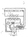
- the figure 1 represents a first embodiment of the invention.
- a thermal management system 1 comprises an air conditioning loop 2, a main circuit 16 and a secondary circuit 26.
- This thermal management system 1 of the vehicle makes it possible at the same time to bring thermal comfort to the passengers of the vehicle via a ventilation installation , heating and / or air conditioning 100 and regulate the temperature of the vehicle components such as the vehicle battery.
- the air conditioning loop 2 in which a refrigerant circulates comprises a compressor 4, a heat-coolant heat exchanger 6, a first expansion device 8, a first heat exchanger 10, a second expansion device 12 and an evaporator 14.
- the refrigerant is R134a, R744 (CO 2 ) or R1234yf.
- the refrigerant fluid is called "refrigerant”.
- the evaporator 14 is located inside a ventilation, heating and / or air conditioning system 100 in which circulates a main air flow F intended to be heat-treated prior to its introduction into the passenger compartment of the vehicle. The evaporator 14 makes it possible to cool the main air flow F and to dehumidify it.
- the compressor 4 is electric and powered by a battery of the vehicle.
- the first 8 and second 12 expansion devices are electronic expansion valves. According to the direction of circulation of refrigerant inside the loop 2, the first expansion device 8 is upstream of the first heat exchanger 10 and the second expansion device 12 is downstream of the first heat exchanger 10. In other words, the first expansion device 8 is located at the inlet of the first heat exchanger 10 and the second expansion device 12 is located at the outlet of the first heat exchanger 10. This particular arrangement makes it possible to use the first heat exchanger 10 to heat the refrigerant to cool the refrigerant.
- the main circuit 16 comprises a pump 18, a first valve 20, a radiator 22, an air-heat exchanger heat exchanger 24 and the heat-exchanger heat-transfer heat exchanger 6.
- the radiator 22 is located inside the installation ventilation, heating and / or air conditioning 100 and allows the heating of the main air flow F.
- the heat-air-heat exchanger 24 is located at the front of the vehicle and is therefore traversed by a flow of outside air Fe.
- a heat transfer fluid (hereinafter called "coolant") circulates inside the main circuit 16. This coolant is brine water for example.
- the first valve 20 is a three-way valve for directing the coolant either to the radiator 22 or to the air-heat exchanger heat exchanger 24. In fact, the radiator 22 and the air-heat-exchanger heat exchanger 24 are arranged in parallel with the pump 18 and the coolant-coolant heat exchanger 6.
- the secondary circuit 26 in which a heat transfer fluid such as brine comprises an additional pump 28, a first auxiliary 30, a second auxiliary 32, a second valve 34, a second heat exchanger 36 and an external heat exchanger 38
- the second valve 34 is a three-valve valve for directing the coolant either to the second heat exchanger 36 or to the external heat exchanger 38.
- the second heat exchanger 36 and the external heat exchanger 38 are arranged in parallel with the additional pump 28 and the first 30 and second 32 auxiliaries.
- the main circuit 16 and the secondary circuit 26 are independent of each other. More precisely, these two circuits are fluidly independent, that is to say that the heat transfer fluid circulating inside the main circuit 16 does not circulate inside the secondary circuit 26.
- the main circuit 16 and the secondary circuit 26 are also fluidly independent of the loop 2 in which the refrigerant circulates. Thus, the coolant and the refrigerant can not mix.
- the main circuit 16 thermally exchanges with the loop 2 via the heat exchanger-heat transfer heat exchanger 6. This heat exchange between the refrigerant of the loop 2 and the coolant of the main circuit 16 will be described later.
- the secondary circuit 26 thermally exchanges with the loop 2 by means of a heat exchange device 40.
- This heat exchange device 40 comprises the first heat exchanger 10, the second heat exchanger 36 and a thermal storage means M Housed inside the heat exchange device 40, and more particularly inside a compartment not shown, the thermal storage means M is a phase-change material, such as water or water. paraffin.
- the heat exchange device 40 is usable either as a source of heat (caloric delivery) or as a heat sink (delivery of frigories).
- the heat exchange device also includes an enclosure 42 closed.
- the first heat exchanger 10, the second heat exchanger 36 and the thermal storage means M are housed inside this enclosure 42.
- “Closed" means that the heat exchanges inside the enclosure heat exchange device are not influenced by external elements such as outdoor air flow. Thermal insulation with respect to the outside of the device is therefore achieved by the enclosure 42.
- the two heat exchangers of the heat exchange device 40 are distinct from each other. Indeed, the first 10 and the second 36 heat exchangers belong respectively to the loop 2 and the secondary circuit 26.
- the heat exchange device 40 is connected to both the loop 2 and the secondary circuit 26. For this it comprises a first inlet 44 and a first outlet 46 fluidly connected to the first heat exchanger 10.
- the device 40 also comprises a second inlet 48 and a second outlet 50 fluidly connected to the second heat exchanger 36.
- the operation of the thermal management system 1 makes it possible, depending on the external climatic conditions (winter or summer conditions), to provide optimum thermal comfort for the passengers of the vehicle without consuming a large amount of electrical energy from the battery of the vehicle. vehicle.
- the thermal management system In winter conditions (outdoor air temperature less than or equal to 5 ° C), the thermal management system operates to heat the main airflow F.
- the management system operates in a heating mode.
- the heat exchange device 40 In a heating mode, the heat exchange device 40 is then loaded in calories at its optimum level.
- the calorie load is achieved by connecting to the home network the vehicle to heat the means of thermal storage M.
- the temperature of the thermal storage means is 90 ° C.
- the loop 2 is implemented in a "heat pump” mode.
- Compressor 4 is on and compresses the refrigerant.
- the refrigerant At the outlet of the compressor 4, the refrigerant is at high temperature and high pressure.
- the refrigerant then passes inside the heat-coolant heat exchanger 6 in which it exchanges its heat (heat) with the coolant of the main circuit 16 flowing inside the heat-coolant heat exchanger 6. In this way, the refrigerant cools and the coolant is charged in calories.
- the refrigerant-heat transfer heat exchanger 6 the refrigerant reaches the first expansion device 8 in which it undergoes a relaxation, which lowers its temperature and its pressure.
- the refrigerant is then at a lower temperature than that of the thermal storage means M of the heat exchange device 40.
- the second expansion device 12 is open so as not to impact the thermodynamic cycle of the refrigerant.
- the refrigerant does not undergo any expansion by passing inside the second expansion device 12.
- the refrigerant circulates in the evaporator 14 and then returns to the compressor 4.
- the temperature of the refrigerant during its passage inside the evaporator 14 is close to that of the temperature of the main air flow F from outside the vehicle.
- the heat exchange between the refrigerant and the main air flow F inside the evaporator 14 is negligible.
- the loop 2 comprises a valve and an associated bypass line to prevent the passage of refrigerant inside the evaporator 14 and guide the refrigerant of the second expansion device 12 directly to the compressor 4.
- This variant avoids any unwanted heat exchange between the refrigerant and the main air flow F inside the evaporator when it is desired to heat the main air flow F.
- the main circuit 16 receives calories via the refrigerant-heat transfer heat exchanger 6.
- the circuit then operates in the following manner.
- the coolant charged in calories inside the heat exchanger-heat transfer heat exchanger 6 passes into the pump 18 and then into the first valve 20, which directs the coolant to the radiator 22.
- the calories transported by the coolant are then exchanged with the main air flow F passing through the radiator 22 to heat it.
- the coolant, unloaded in calories joins the coolant heat transfer heat exchanger 6.
- the secondary circuit 26 is also used when the vehicle is traveling. Indeed, since the vehicle is in operation, the components such as the battery, the propulsion system or traction, or any electronic device releasing heat, are solicited and generate calories. However, it is necessary for the proper functioning of these components and their lifetime, to evacuate the calories produced.
- a first auxiliary 30 allows to evacuate the calories produced by the components to the coolant. In other words, the first auxiliary 30 acts as a heat sink.
- the calories produced by the components are then exchanged with the coolant inside the first auxiliary 30 and then directed towards the second heat exchanger 36 of the heat exchange device 40. In this way, the storage means Thermal M is recharged by the calories coming from the components.
- the circuit 26 is then as follows: additional pump 28, first auxiliary 30, second auxiliary 32, second valve 34, second heat exchanger 36 and then return to additional pump 28.
- the thermal management system During summer conditions (outdoor air temperature greater than or equal to 30 ° C), the thermal management system is in cooling mode. Under such climatic conditions, the heat exchange device 40 is optimally charged in cold (cold) condition. Charging is done through a connection to a home network.
- the temperature of the thermal storage means is less than or equal to 5 ° C.
- the refrigerant is compressed in the compressor 4, is discharged in calories by passing inside the heat-coolant-heat exchanger 6, passes into the first expansion device 8 undergoing a first expansion and circulates within the first heat exchanger 10. Since the thermal storage means M comprises a large amount of frigories, the refrigerant passing inside the first heat exchanger 10 undergoes additional cooling compared with that undergone by the first heat exchanger 10. This additional cooling improves the coefficient of performance of the loop 2. Then the refrigerant is expanded by the second expansion device 12 and is thus in the state of low pressure and low temperature. . The refrigerant is finally heated by passing inside the evaporator 14, which cools the main air flow F.
- the combined use of the first 8 and the second 12 expansion devices minimizes the use of the device. heat exchange 40 and improves the coefficient of performance of the loop 2.
- the action of the two expansion devices avoids rapidly discharging in frigories the thermal storage means M, which results in a longer use of the system. thermal management 1 during long trips of the vehicle in summer.
- the two detents successively undergone by the refrigerant make it possible to lower its temperature without using a large quantity of frigories of the heat exchange device 40.
- the coolant charged in calories from the refrigerant at the heat exchanger coolant-coolant 6, passes into the pump 18, the first valve 20, the air-heat exchanger heat exchanger 24 and returns to the heat exchanger heat-coolant 6.
- the calories of the coolant are removed from the thermal management system 1 via the outside air flow through the air-heat exchanger heat-exchanger 24.
- the first valve 20 therefore prohibits the passage of the coolant in the radiator 22.
- the coolant circulates in the additional pump 28, in the first auxiliary 30, the second auxiliary 32, the second valve 34, the external heat exchanger 38 and then returns to the additional pump 28.
- the second valve 34 therefore prohibits the passage of the coolant to the second heat exchanger 36.
- the external heat exchanger 38 ensures the cooling of the heat carrier previously loaded in calories via the first auxiliary 30 due to the implementation of the vehicle components.
- the loop 2 and the secondary circuit 26 operate in the same way as that of the cooling mode.
- the main circuit 16 operates as that of the heating mode.
- the evaporator 14 cools and dehumidifies the main air flow F and the radiator 22 heats the main air flow F before its introduction into the passenger compartment of the vehicle.
- the thermal management system 1 furthermore makes it possible to carry out a cooling mode of the vehicle components. This mode occurs when the vehicle rolls without the passengers of the vehicle requires heat treatment of the cabin air. Thus, the loop 2 is not implemented nor the main circuit 16. Only the secondary circuit 26 operates.
- the coolant, circulating under the action of the additional pump 28, passes inside the first auxiliary 30 and is charged in calories from the components.
- the coolant passes through the second auxiliary 32 in which no heat exchange occurs and reaches the second heat exchanger 36.
- the coolant cools by heat exchanging with the thermal storage means M of the heat exchange device 40.
- This component cooling mode can also be used when the vehicle is stationary and connected to a home network.
- the thermal storage means M When the heat exchange device 40 is used in an operating mode, the thermal storage means M is used. Accordingly, either the calories or the frigories are used and are removed from the heat exchange device 40. After a period of use, the thermal storage means M must be recharged in calories or frigories.
- the first solution is to connect the heat exchange device 40 to an apparatus capable of reloading in cold energy the thermal storage means M.
- the apparatus independent of the thermal management system 1, is for example disposed in a service station or in a a home network.
- the second solution occurs when the outside air temperature is lower than that of the thermal storage means M.
- the outside air flow is assimilated to a source of frigories.
- Only the secondary circuit 26 is used to restore this cooling capacity.
- the additional pump 28 circulates the coolant through the second heat exchanger which exchanges frigories from the outside air flow passing through the air-heat exchanger heat exchanger 24.
- This solution then requires an additional valve and an associated pipe for putting in series the second heat exchanger 36 and the air-heat-exchange heat exchanger 24.
- the third solution comes during summer conditions.
- the loop 2 and the main circuit 16 operate as in cooling mode.
- the secondary circuit 26 is off.
- the heat exchange device 40 is recharged in frigories via the first heat exchanger 10 in which the refrigerant yields these frigories by means of thermal storage M.
- the loop 2 comprises a valve and an associated bypass line making it possible to bypass the evaporator 14.
- the loop 2 comprises a valve and an associated bypass line making it possible to bypass the evaporator 14.
- the first solution is to connect the heat exchange device 40 to a device capable of recharging the heat storage means M.
- the apparatus independent of the thermal management system 1, is for example disposed in a service station or in a service station. a home network.
- the second solution occurs when the outside air temperature is higher than that of the thermal storage means M.
- the outside air flow is considered a source of calories.
- Only the secondary circuit 26 is used to restore this heating capacity.
- the additional pump 28 circulates the coolant through the second heat exchanger which exchanges calories from the outside air flow passing through the air-heat exchanger heat exchanger 24.
- This solution then requires an additional valve and an associated pipe for putting in series the second heat exchanger 36 and the air-heat-exchange heat exchanger 24.
- the third solution is to use the second auxiliary 32.
- the second auxiliary 32 comprises a heat sink provided with a resistive element such as a stone with a positive temperature coefficient.
- the secondary circuit 26 is used in which the coolant is charged in calories by passing inside the second auxiliary 32, these calories being then transmitted to the thermal storage means M via the second heat exchanger 36.
- a fourth solution is to dispose a resistive element as described above in the heat exchange device 40.
- the resistive element is supplied with electricity and heats up so as to increase the temperature of the thermal storage means M.
- the fifth solution is to use the loop 2.
- the main circuit 16 and secondary 26 are not used.
- the compressed refrigerant passes inside the heat exchanger-heat transfer heat exchanger 6 by discharging very little of these calories because the coolant in the main circuit 16 does not circulate.
- the majority of the calories of the refrigerant is therefore transferred to the thermal storage means M via the first heat exchanger 10.
- the refrigerant then passes into the second expansion device 12 and in the evaporator in which it heats up.
- This solution corresponds to a stationary vehicle.
- the main circuit 16 comprises an electric heating device upstream of the radiator 22 according to the direction of circulation of the coolant. This electric heating device completes the heating of the coolant to improve the heating of the main air flow F through the radiator 22.
- the thermal management system 1 comprises an additional circuit comprising a pump, a secondary heat exchanger located upstream or downstream in the direction of flow of the main air flow F inside the installation. of ventilation, heating and / or air conditioning 100 and a heat exchanger located inside the heat exchange device 40.
- a thermal management system it is possible to use the frigories or the calories of the storage means thermal M to cool or heat the main air flow F without implementing the loop 2 and / or the main circuit 16. A gain in power consumption of the battery is then obtained.
Applications Claiming Priority (1)
| Application Number | Priority Date | Filing Date | Title |
|---|---|---|---|
| FR0902712A FR2946419B1 (fr) | 2009-06-05 | 2009-06-05 | Dispositif d'echange thermique et systeme de gestion thermique |
Publications (2)
| Publication Number | Publication Date |
|---|---|
| EP2258571A1 true EP2258571A1 (de) | 2010-12-08 |
| EP2258571B1 EP2258571B1 (de) | 2016-04-20 |
Family
ID=41479056
Family Applications (1)
| Application Number | Title | Priority Date | Filing Date |
|---|---|---|---|
| EP10164313.8A Active EP2258571B1 (de) | 2009-06-05 | 2010-05-28 | Wärmetauschvorrichtung und Wärmeregelungssystem |
Country Status (4)
| Country | Link |
|---|---|
| EP (1) | EP2258571B1 (de) |
| JP (1) | JP6139047B2 (de) |
| CN (1) | CN101949658B (de) |
| FR (1) | FR2946419B1 (de) |
Cited By (6)
| Publication number | Priority date | Publication date | Assignee | Title |
|---|---|---|---|---|
| WO2012146368A1 (fr) * | 2011-04-29 | 2012-11-01 | Valeo Systemes Thermiques | Ensemble comprenant un circuit de fluide refrigerant et un circuit de fluide caloporteur |
| US9327577B2 (en) | 2013-01-25 | 2016-05-03 | GM Global Technology Operations LLC | Vehicle heat pump system and method utilizing thermal storage |
| FR3052856A1 (fr) * | 2016-06-21 | 2017-12-22 | Valeo Systemes Thermiques | Boucle de circulation d’un fluide refrigerant pour vehicule |
| CN110397522A (zh) * | 2019-08-01 | 2019-11-01 | 合肥丰蓝电器有限公司 | 一种制热量无级可调的车载燃油加热系统 |
| WO2020065218A1 (fr) | 2018-09-27 | 2020-04-02 | Valeo Systemes Thermiques | Procédé de gestion thermique pour dispositif de gestion thermique, en particulier pour un habitacle de véhicule |
| WO2020094997A1 (fr) | 2018-11-09 | 2020-05-14 | Valeo Systemes Thermiques | Dispositif et procédé de gestion thermique pour habitacle de véhicule |
Families Citing this family (22)
| Publication number | Priority date | Publication date | Assignee | Title |
|---|---|---|---|---|
| KR101241222B1 (ko) | 2011-07-21 | 2013-03-13 | 기아자동차주식회사 | 차량용 히트펌프 시스템 제어방법 |
| JP5780166B2 (ja) | 2011-02-11 | 2015-09-16 | 株式会社デンソー | ヒートポンプサイクル |
| KR101241223B1 (ko) * | 2011-03-23 | 2013-03-25 | 기아자동차주식회사 | 차량용 히트펌프 시스템 및 그 제어방법 |
| JP5989328B2 (ja) * | 2011-11-17 | 2016-09-07 | トヨタ自動車株式会社 | 熱交換装置 |
| ES2496441T3 (es) * | 2011-12-07 | 2014-09-19 | Valeo Systèmes Thermiques | Pieza de acoplamiento entre un dispositivo de expansión y una pared |
| JP2014037179A (ja) * | 2012-08-13 | 2014-02-27 | Calsonic Kansei Corp | 電動車両用熱管理システム |
| JP5771168B2 (ja) * | 2012-08-28 | 2015-08-26 | 株式会社東芝 | 蓄熱装置、空調装置及び蓄熱方法 |
| CN103855445B (zh) * | 2012-12-04 | 2016-12-07 | 上海汽车集团股份有限公司 | 一种热管理系统、电池热管理系统、电动车和混合动力车 |
| WO2015103548A1 (en) * | 2014-01-03 | 2015-07-09 | Quantumscape Corporation | Thermal management system for vehicles with an electric powertrain |
| DE102013205844B4 (de) * | 2013-04-03 | 2015-08-20 | O. Salm & Co. Gmbh | Vorrichtung und verfahren zum erwärmen eines fermentierbaren ausgangsstoffes zur getränkeherstellung |
| US11011783B2 (en) | 2013-10-25 | 2021-05-18 | Quantumscape Battery, Inc. | Thermal and electrical management of battery packs |
| CN104633991B (zh) * | 2013-11-13 | 2019-01-22 | 马勒国际公司 | 用于优选在机动车中冷却和/或加热媒介的方法以及吸附热和冷存储系统 |
| US9834114B2 (en) | 2014-08-27 | 2017-12-05 | Quantumscape Corporation | Battery thermal management system and methods of use |
| CN107407533B (zh) * | 2015-03-20 | 2020-02-07 | 西门子歌美飒可再生能源公司 | 热能存储设备 |
| JP6791052B2 (ja) * | 2017-07-31 | 2020-11-25 | 株式会社デンソー | 空調装置 |
| DE102018217298A1 (de) * | 2017-10-12 | 2019-04-18 | Hanon Systems | Batterie-Wärmemanagement-System für Hybrid und vollelektrische Fahrzeuge unter Verwendung eines Heizkondensators |
| FR3078024A1 (fr) * | 2018-02-21 | 2019-08-23 | Psa Automobiles Sa | Dispositif de climatisation pour vehicule automobile et vehicule automobile comportant un tel dispositif |
| DE102018104410A1 (de) * | 2018-02-27 | 2019-08-29 | Hanon Systems | Klimatisierungssystem eines Kraftfahrzeugs und Verfahren zum Betreiben des Klimatisierungssystems |
| KR102510371B1 (ko) | 2018-04-27 | 2023-03-17 | 한온시스템 주식회사 | 차량용 열교환 시스템 |
| CN109455059B (zh) * | 2018-11-16 | 2020-07-03 | 江西新电汽车空调系统有限公司 | 集合水冷冷凝器和水冷蒸发器的热泵空调及热管理系统 |
| EP3901531A4 (de) * | 2018-12-18 | 2021-12-29 | Mitsubishi Electric Corporation | Klimatisierungsvorrichtung |
| CN111071072A (zh) * | 2019-12-31 | 2020-04-28 | 潍柴动力股份有限公司 | 燃料电池冷却模块及燃料电池冷却系统 |
Citations (6)
| Publication number | Priority date | Publication date | Assignee | Title |
|---|---|---|---|---|
| DE19530378C1 (de) * | 1995-08-18 | 1997-03-06 | Laengerer & Reich Gmbh & Co | Wärmespeicher für ein Kraftfahrzeug |
| EP0800940A2 (de) | 1996-04-10 | 1997-10-15 | Denso Corporation | Klimaanlagesystem für Elektrofahrzeuge |
| FR2808245A1 (fr) | 2000-04-28 | 2001-11-02 | Denso Corp | Dispositif de conditionnement d'air pour vehicule |
| US20030167925A1 (en) * | 2002-03-06 | 2003-09-11 | Yasukazu Aikawa | Heat storage system for vehicle, with adsorbent |
| DE10233415A1 (de) * | 2002-07-23 | 2004-02-19 | Webasto Thermosysteme International Gmbh | System zum Heizen und Kühlen eines Innenraums eines Fahrzeugs |
| WO2007110724A1 (en) * | 2006-03-27 | 2007-10-04 | Toyota Jidosha Kabushiki Kaisha | Heat storage device |
Family Cites Families (6)
| Publication number | Priority date | Publication date | Assignee | Title |
|---|---|---|---|---|
| JPS6217570A (ja) * | 1985-07-15 | 1987-01-26 | 日産自動車株式会社 | 冷房装置の制御方法 |
| JPS63201494A (ja) * | 1987-02-18 | 1988-08-19 | Hitachi Ltd | 蓄熱熱交換器 |
| US5553662A (en) * | 1993-12-10 | 1996-09-10 | Store Heat & Producte Energy, Inc. | Plumbed thermal energy storage system |
| CH686641A5 (fr) * | 1995-03-10 | 1996-05-15 | Michel Schmidt | Accumulateur de chaleur. |
| NO320664B1 (no) * | 2001-12-19 | 2006-01-16 | Sinvent As | System for oppvarming og kjoling av kjoretoy |
| JP4862465B2 (ja) * | 2006-04-13 | 2012-01-25 | トヨタ自動車株式会社 | 蓄熱型熱交換器および空調システム |
-
2009
- 2009-06-05 FR FR0902712A patent/FR2946419B1/fr not_active Expired - Fee Related
-
2010
- 2010-05-28 EP EP10164313.8A patent/EP2258571B1/de active Active
- 2010-06-07 CN CN201010504228.6A patent/CN101949658B/zh active Active
- 2010-06-07 JP JP2010129661A patent/JP6139047B2/ja active Active
Patent Citations (6)
| Publication number | Priority date | Publication date | Assignee | Title |
|---|---|---|---|---|
| DE19530378C1 (de) * | 1995-08-18 | 1997-03-06 | Laengerer & Reich Gmbh & Co | Wärmespeicher für ein Kraftfahrzeug |
| EP0800940A2 (de) | 1996-04-10 | 1997-10-15 | Denso Corporation | Klimaanlagesystem für Elektrofahrzeuge |
| FR2808245A1 (fr) | 2000-04-28 | 2001-11-02 | Denso Corp | Dispositif de conditionnement d'air pour vehicule |
| US20030167925A1 (en) * | 2002-03-06 | 2003-09-11 | Yasukazu Aikawa | Heat storage system for vehicle, with adsorbent |
| DE10233415A1 (de) * | 2002-07-23 | 2004-02-19 | Webasto Thermosysteme International Gmbh | System zum Heizen und Kühlen eines Innenraums eines Fahrzeugs |
| WO2007110724A1 (en) * | 2006-03-27 | 2007-10-04 | Toyota Jidosha Kabushiki Kaisha | Heat storage device |
Cited By (14)
| Publication number | Priority date | Publication date | Assignee | Title |
|---|---|---|---|---|
| FR2974624A1 (fr) * | 2011-04-29 | 2012-11-02 | Valeo Systemes Thermiques | Ensemble comprenant un circuit de fluide refrigerant et un circuit de fluide caloporteur |
| WO2012146368A1 (fr) * | 2011-04-29 | 2012-11-01 | Valeo Systemes Thermiques | Ensemble comprenant un circuit de fluide refrigerant et un circuit de fluide caloporteur |
| US9327577B2 (en) | 2013-01-25 | 2016-05-03 | GM Global Technology Operations LLC | Vehicle heat pump system and method utilizing thermal storage |
| DE102014100555B4 (de) | 2013-01-25 | 2023-05-17 | GM Global Technology Operations LLC (n. d. Gesetzen des Staates Delaware) | Wärmepumpensystem zur verwendung in einem fahrzeug |
| CN109789750B (zh) * | 2016-06-21 | 2022-05-10 | 法雷奥热系统公司 | 用于车辆的冷却剂循环回路 |
| FR3052856A1 (fr) * | 2016-06-21 | 2017-12-22 | Valeo Systemes Thermiques | Boucle de circulation d’un fluide refrigerant pour vehicule |
| WO2017220902A1 (fr) * | 2016-06-21 | 2017-12-28 | Valeo Systemes Thermiques | Boucle de circulation d'un fluide refrigerant pour vehicule |
| CN109789750A (zh) * | 2016-06-21 | 2019-05-21 | 法雷奥热系统公司 | 用于车辆的冷却剂循环回路 |
| WO2020065218A1 (fr) | 2018-09-27 | 2020-04-02 | Valeo Systemes Thermiques | Procédé de gestion thermique pour dispositif de gestion thermique, en particulier pour un habitacle de véhicule |
| FR3086582A1 (fr) | 2018-09-27 | 2020-04-03 | Valeo Systemes Thermiques | Procede de gestion thermique pour dispositif de gestion thermique, en particulier pour un habitacle de vehicule |
| WO2020094997A1 (fr) | 2018-11-09 | 2020-05-14 | Valeo Systemes Thermiques | Dispositif et procédé de gestion thermique pour habitacle de véhicule |
| FR3088260A1 (fr) | 2018-11-09 | 2020-05-15 | Valeo Systemes Thermiques | Dispositif et procede de gestion thermique pour habitacle de vehicule |
| CN110397522A (zh) * | 2019-08-01 | 2019-11-01 | 合肥丰蓝电器有限公司 | 一种制热量无级可调的车载燃油加热系统 |
| CN110397522B (zh) * | 2019-08-01 | 2024-04-09 | 合肥丰蓝电器有限公司 | 一种制热量无级可调的车载燃油加热系统 |
Also Published As
| Publication number | Publication date |
|---|---|
| EP2258571B1 (de) | 2016-04-20 |
| FR2946419B1 (fr) | 2014-02-14 |
| CN101949658B (zh) | 2015-10-07 |
| JP6139047B2 (ja) | 2017-05-31 |
| JP2010281561A (ja) | 2010-12-16 |
| CN101949658A (zh) | 2011-01-19 |
| FR2946419A1 (fr) | 2010-12-10 |
Similar Documents
| Publication | Publication Date | Title |
|---|---|---|
| EP2258571B1 (de) | Wärmetauschvorrichtung und Wärmeregelungssystem | |
| EP2263894B1 (de) | Wärmemanagmentsystem mit einem Klimaanlagenkreislauf und einem Kältemittelkreislauf | |
| EP2791596B1 (de) | Vorrichtung zur klimatisierung eines antriebsstrangs und eines fahrzeuginnenraums | |
| EP2817163B1 (de) | Vorrichtung zum wärmemanagement einer kabine und des antriebsstrangs eines fahrzeugs | |
| EP2643643B2 (de) | Vorrichtung zur wärmeregelung eines insassenraums eines fahrzeuges | |
| EP2437955B1 (de) | Multifunktions-thermomanagement-vorrichtung und -verfahren eines elektrofahrzeugs | |
| EP3471978B1 (de) | Kühlmittelkreislauf für fahrzeug | |
| EP2582534B1 (de) | Heisskonditionierungssystem für ein kraftfahrzeug | |
| FR2834778A1 (fr) | Dispositif de gestion thermique, notamment pour vehicule automobile equipe d'une pile a combustible | |
| WO2012055956A1 (fr) | Dispositif de conditionnement thermique d'une chaîne de traction et d'un habitacle de véhicule | |
| EP3727910B1 (de) | Betriebsverfahren eines thermischen steuersystems eines hybrid- oder elektrokraftfahrzeugs | |
| EP2841288A1 (de) | Heizungs-, belüftungs- und/oder klimaanlage mit einer vorrichtung zur steuerung der temperatur einer batterie und verfahren zur implementierung davon | |
| WO2019138176A1 (fr) | Systeme de refroidissement d'au moins une batterie de vehicule automobile | |
| WO2019155179A1 (fr) | Systeme de refroidissement d'au moins une batterie de véhicule automobile | |
| FR3004387A1 (fr) | Systeme de regulation thermique de l'habitacle d'un vehicule electrique | |
| FR3075705A1 (fr) | Circuit de fluide refrigerant pour vehicule, adapte a une charge rapide d’un dispositif de stockage electrique | |
| WO2019186077A1 (fr) | Système de conditionnement thermique d'un dispositif de stockage électrique équipant un véhicule | |
| WO2014183972A1 (fr) | Systeme de climatisation auto-degivrant | |
| EP4100268A1 (de) | Vorrichtung zur wärmerückgewinnung und regelung für ein elektrofahrzeug mit einem elektrochemischen generator mit einem hlk-system | |
| FR3077336A1 (fr) | Circuit de fluide refrigerant | |
| WO2014118208A1 (fr) | Dispositif de conditionnement thermique pour vehicule automobile et installation de chauffage, ventilation et/ou climatisation correspondante |
Legal Events
| Date | Code | Title | Description |
|---|---|---|---|
| PUAI | Public reference made under article 153(3) epc to a published international application that has entered the european phase |
Free format text: ORIGINAL CODE: 0009012 |
|
| AK | Designated contracting states |
Kind code of ref document: A1 Designated state(s): AL AT BE BG CH CY CZ DE DK EE ES FI FR GB GR HR HU IE IS IT LI LT LU LV MC MK MT NL NO PL PT RO SE SI SK SM TR |
|
| AX | Request for extension of the european patent |
Extension state: BA ME RS |
|
| 17P | Request for examination filed |
Effective date: 20110607 |
|
| 17Q | First examination report despatched |
Effective date: 20130205 |
|
| GRAP | Despatch of communication of intention to grant a patent |
Free format text: ORIGINAL CODE: EPIDOSNIGR1 |
|
| INTG | Intention to grant announced |
Effective date: 20151208 |
|
| GRAS | Grant fee paid |
Free format text: ORIGINAL CODE: EPIDOSNIGR3 |
|
| GRAA | (expected) grant |
Free format text: ORIGINAL CODE: 0009210 |
|
| AK | Designated contracting states |
Kind code of ref document: B1 Designated state(s): AL AT BE BG CH CY CZ DE DK EE ES FI FR GB GR HR HU IE IS IT LI LT LU LV MC MK MT NL NO PL PT RO SE SI SK SM TR |
|
| REG | Reference to a national code |
Ref country code: GB Ref legal event code: FG4D Free format text: NOT ENGLISH |
|
| REG | Reference to a national code |
Ref country code: CH Ref legal event code: EP |
|
| REG | Reference to a national code |
Ref country code: AT Ref legal event code: REF Ref document number: 792004 Country of ref document: AT Kind code of ref document: T Effective date: 20160515 |
|
| REG | Reference to a national code |
Ref country code: IE Ref legal event code: FG4D Free format text: LANGUAGE OF EP DOCUMENT: FRENCH |
|
| REG | Reference to a national code |
Ref country code: DE Ref legal event code: R096 Ref document number: 602010032395 Country of ref document: DE |
|
| REG | Reference to a national code |
Ref country code: SE Ref legal event code: TRGR |
|
| REG | Reference to a national code |
Ref country code: LT Ref legal event code: MG4D |
|
| PG25 | Lapsed in a contracting state [announced via postgrant information from national office to epo] |
Ref country code: BE Free format text: LAPSE BECAUSE OF NON-PAYMENT OF DUE FEES Effective date: 20160531 |
|
| REG | Reference to a national code |
Ref country code: FR Ref legal event code: PLFP Year of fee payment: 7 |
|
| REG | Reference to a national code |
Ref country code: AT Ref legal event code: MK05 Ref document number: 792004 Country of ref document: AT Kind code of ref document: T Effective date: 20160420 |
|
| REG | Reference to a national code |
Ref country code: NL Ref legal event code: MP Effective date: 20160420 |
|
| PG25 | Lapsed in a contracting state [announced via postgrant information from national office to epo] |
Ref country code: LT Free format text: LAPSE BECAUSE OF FAILURE TO SUBMIT A TRANSLATION OF THE DESCRIPTION OR TO PAY THE FEE WITHIN THE PRESCRIBED TIME-LIMIT Effective date: 20160420 Ref country code: PL Free format text: LAPSE BECAUSE OF FAILURE TO SUBMIT A TRANSLATION OF THE DESCRIPTION OR TO PAY THE FEE WITHIN THE PRESCRIBED TIME-LIMIT Effective date: 20160420 Ref country code: NL Free format text: LAPSE BECAUSE OF FAILURE TO SUBMIT A TRANSLATION OF THE DESCRIPTION OR TO PAY THE FEE WITHIN THE PRESCRIBED TIME-LIMIT Effective date: 20160420 Ref country code: NO Free format text: LAPSE BECAUSE OF FAILURE TO SUBMIT A TRANSLATION OF THE DESCRIPTION OR TO PAY THE FEE WITHIN THE PRESCRIBED TIME-LIMIT Effective date: 20160720 Ref country code: FI Free format text: LAPSE BECAUSE OF FAILURE TO SUBMIT A TRANSLATION OF THE DESCRIPTION OR TO PAY THE FEE WITHIN THE PRESCRIBED TIME-LIMIT Effective date: 20160420 |
|
| PG25 | Lapsed in a contracting state [announced via postgrant information from national office to epo] |
Ref country code: HR Free format text: LAPSE BECAUSE OF FAILURE TO SUBMIT A TRANSLATION OF THE DESCRIPTION OR TO PAY THE FEE WITHIN THE PRESCRIBED TIME-LIMIT Effective date: 20160420 Ref country code: ES Free format text: LAPSE BECAUSE OF FAILURE TO SUBMIT A TRANSLATION OF THE DESCRIPTION OR TO PAY THE FEE WITHIN THE PRESCRIBED TIME-LIMIT Effective date: 20160420 Ref country code: LV Free format text: LAPSE BECAUSE OF FAILURE TO SUBMIT A TRANSLATION OF THE DESCRIPTION OR TO PAY THE FEE WITHIN THE PRESCRIBED TIME-LIMIT Effective date: 20160420 Ref country code: AT Free format text: LAPSE BECAUSE OF FAILURE TO SUBMIT A TRANSLATION OF THE DESCRIPTION OR TO PAY THE FEE WITHIN THE PRESCRIBED TIME-LIMIT Effective date: 20160420 Ref country code: GR Free format text: LAPSE BECAUSE OF FAILURE TO SUBMIT A TRANSLATION OF THE DESCRIPTION OR TO PAY THE FEE WITHIN THE PRESCRIBED TIME-LIMIT Effective date: 20160721 Ref country code: PT Free format text: LAPSE BECAUSE OF FAILURE TO SUBMIT A TRANSLATION OF THE DESCRIPTION OR TO PAY THE FEE WITHIN THE PRESCRIBED TIME-LIMIT Effective date: 20160822 |
|
| REG | Reference to a national code |
Ref country code: CH Ref legal event code: PL |
|
| REG | Reference to a national code |
Ref country code: DE Ref legal event code: R097 Ref document number: 602010032395 Country of ref document: DE |
|
| PG25 | Lapsed in a contracting state [announced via postgrant information from national office to epo] |
Ref country code: CH Free format text: LAPSE BECAUSE OF NON-PAYMENT OF DUE FEES Effective date: 20160531 Ref country code: LI Free format text: LAPSE BECAUSE OF NON-PAYMENT OF DUE FEES Effective date: 20160531 Ref country code: RO Free format text: LAPSE BECAUSE OF FAILURE TO SUBMIT A TRANSLATION OF THE DESCRIPTION OR TO PAY THE FEE WITHIN THE PRESCRIBED TIME-LIMIT Effective date: 20160420 Ref country code: EE Free format text: LAPSE BECAUSE OF FAILURE TO SUBMIT A TRANSLATION OF THE DESCRIPTION OR TO PAY THE FEE WITHIN THE PRESCRIBED TIME-LIMIT Effective date: 20160420 Ref country code: DK Free format text: LAPSE BECAUSE OF FAILURE TO SUBMIT A TRANSLATION OF THE DESCRIPTION OR TO PAY THE FEE WITHIN THE PRESCRIBED TIME-LIMIT Effective date: 20160420 Ref country code: MC Free format text: LAPSE BECAUSE OF FAILURE TO SUBMIT A TRANSLATION OF THE DESCRIPTION OR TO PAY THE FEE WITHIN THE PRESCRIBED TIME-LIMIT Effective date: 20160420 Ref country code: CZ Free format text: LAPSE BECAUSE OF FAILURE TO SUBMIT A TRANSLATION OF THE DESCRIPTION OR TO PAY THE FEE WITHIN THE PRESCRIBED TIME-LIMIT Effective date: 20160420 Ref country code: SK Free format text: LAPSE BECAUSE OF FAILURE TO SUBMIT A TRANSLATION OF THE DESCRIPTION OR TO PAY THE FEE WITHIN THE PRESCRIBED TIME-LIMIT Effective date: 20160420 |
|
| REG | Reference to a national code |
Ref country code: IE Ref legal event code: MM4A |
|
| PLBE | No opposition filed within time limit |
Free format text: ORIGINAL CODE: 0009261 |
|
| STAA | Information on the status of an ep patent application or granted ep patent |
Free format text: STATUS: NO OPPOSITION FILED WITHIN TIME LIMIT |
|
| PG25 | Lapsed in a contracting state [announced via postgrant information from national office to epo] |
Ref country code: SM Free format text: LAPSE BECAUSE OF FAILURE TO SUBMIT A TRANSLATION OF THE DESCRIPTION OR TO PAY THE FEE WITHIN THE PRESCRIBED TIME-LIMIT Effective date: 20160420 |
|
| GBPC | Gb: european patent ceased through non-payment of renewal fee |
Effective date: 20160720 |
|
| 26N | No opposition filed |
Effective date: 20170123 |
|
| REG | Reference to a national code |
Ref country code: FR Ref legal event code: PLFP Year of fee payment: 8 |
|
| PG25 | Lapsed in a contracting state [announced via postgrant information from national office to epo] |
Ref country code: IE Free format text: LAPSE BECAUSE OF NON-PAYMENT OF DUE FEES Effective date: 20160528 Ref country code: SI Free format text: LAPSE BECAUSE OF FAILURE TO SUBMIT A TRANSLATION OF THE DESCRIPTION OR TO PAY THE FEE WITHIN THE PRESCRIBED TIME-LIMIT Effective date: 20160420 Ref country code: GB Free format text: LAPSE BECAUSE OF NON-PAYMENT OF DUE FEES Effective date: 20160720 |
|
| REG | Reference to a national code |
Ref country code: FR Ref legal event code: PLFP Year of fee payment: 9 |
|
| PG25 | Lapsed in a contracting state [announced via postgrant information from national office to epo] |
Ref country code: CY Free format text: LAPSE BECAUSE OF FAILURE TO SUBMIT A TRANSLATION OF THE DESCRIPTION OR TO PAY THE FEE WITHIN THE PRESCRIBED TIME-LIMIT Effective date: 20160420 Ref country code: HU Free format text: LAPSE BECAUSE OF FAILURE TO SUBMIT A TRANSLATION OF THE DESCRIPTION OR TO PAY THE FEE WITHIN THE PRESCRIBED TIME-LIMIT; INVALID AB INITIO Effective date: 20100528 |
|
| PG25 | Lapsed in a contracting state [announced via postgrant information from national office to epo] |
Ref country code: MK Free format text: LAPSE BECAUSE OF FAILURE TO SUBMIT A TRANSLATION OF THE DESCRIPTION OR TO PAY THE FEE WITHIN THE PRESCRIBED TIME-LIMIT Effective date: 20160420 Ref country code: IS Free format text: LAPSE BECAUSE OF FAILURE TO SUBMIT A TRANSLATION OF THE DESCRIPTION OR TO PAY THE FEE WITHIN THE PRESCRIBED TIME-LIMIT Effective date: 20160420 Ref country code: TR Free format text: LAPSE BECAUSE OF FAILURE TO SUBMIT A TRANSLATION OF THE DESCRIPTION OR TO PAY THE FEE WITHIN THE PRESCRIBED TIME-LIMIT Effective date: 20160420 Ref country code: LU Free format text: LAPSE BECAUSE OF NON-PAYMENT OF DUE FEES Effective date: 20160528 Ref country code: MT Free format text: LAPSE BECAUSE OF FAILURE TO SUBMIT A TRANSLATION OF THE DESCRIPTION OR TO PAY THE FEE WITHIN THE PRESCRIBED TIME-LIMIT Effective date: 20160420 |
|
| PG25 | Lapsed in a contracting state [announced via postgrant information from national office to epo] |
Ref country code: BG Free format text: LAPSE BECAUSE OF FAILURE TO SUBMIT A TRANSLATION OF THE DESCRIPTION OR TO PAY THE FEE WITHIN THE PRESCRIBED TIME-LIMIT Effective date: 20160420 |
|
| PG25 | Lapsed in a contracting state [announced via postgrant information from national office to epo] |
Ref country code: AL Free format text: LAPSE BECAUSE OF FAILURE TO SUBMIT A TRANSLATION OF THE DESCRIPTION OR TO PAY THE FEE WITHIN THE PRESCRIBED TIME-LIMIT Effective date: 20160420 |
|
| PGFP | Annual fee paid to national office [announced via postgrant information from national office to epo] |
Ref country code: IT Payment date: 20210513 Year of fee payment: 12 |
|
| PGFP | Annual fee paid to national office [announced via postgrant information from national office to epo] |
Ref country code: SE Payment date: 20210518 Year of fee payment: 12 |
|
| REG | Reference to a national code |
Ref country code: SE Ref legal event code: EUG |
|
| PG25 | Lapsed in a contracting state [announced via postgrant information from national office to epo] |
Ref country code: SE Free format text: LAPSE BECAUSE OF NON-PAYMENT OF DUE FEES Effective date: 20220529 |
|
| P01 | Opt-out of the competence of the unified patent court (upc) registered |
Effective date: 20230528 |
|
| PG25 | Lapsed in a contracting state [announced via postgrant information from national office to epo] |
Ref country code: IT Free format text: LAPSE BECAUSE OF NON-PAYMENT OF DUE FEES Effective date: 20220528 |
|
| PGFP | Annual fee paid to national office [announced via postgrant information from national office to epo] |
Ref country code: FR Payment date: 20230523 Year of fee payment: 14 Ref country code: DE Payment date: 20230510 Year of fee payment: 14 |