EP2258570A1 - Verfahren zur Steuerung des Fluiddruckes eines hydraulischen Federungszylinders und die Ventilanordnung zur Umsetzung des Verfahrens - Google Patents
Verfahren zur Steuerung des Fluiddruckes eines hydraulischen Federungszylinders und die Ventilanordnung zur Umsetzung des Verfahrens Download PDFInfo
- Publication number
- EP2258570A1 EP2258570A1 EP10164808A EP10164808A EP2258570A1 EP 2258570 A1 EP2258570 A1 EP 2258570A1 EP 10164808 A EP10164808 A EP 10164808A EP 10164808 A EP10164808 A EP 10164808A EP 2258570 A1 EP2258570 A1 EP 2258570A1
- Authority
- EP
- European Patent Office
- Prior art keywords
- valve assembly
- hydraulic cylinder
- instant
- flow
- hydraulic
- Prior art date
- Legal status (The legal status is an assumption and is not a legal conclusion. Google has not performed a legal analysis and makes no representation as to the accuracy of the status listed.)
- Granted
Links
Images


Classifications
-
- F—MECHANICAL ENGINEERING; LIGHTING; HEATING; WEAPONS; BLASTING
- F16—ENGINEERING ELEMENTS AND UNITS; GENERAL MEASURES FOR PRODUCING AND MAINTAINING EFFECTIVE FUNCTIONING OF MACHINES OR INSTALLATIONS; THERMAL INSULATION IN GENERAL
- F16F—SPRINGS; SHOCK-ABSORBERS; MEANS FOR DAMPING VIBRATION
- F16F9/00—Springs, vibration-dampers, shock-absorbers, or similarly-constructed movement-dampers using a fluid or the equivalent as damping medium
- F16F9/32—Details
- F16F9/44—Means on or in the damper for manual or non-automatic adjustment; such means combined with temperature correction
-
- B—PERFORMING OPERATIONS; TRANSPORTING
- B60—VEHICLES IN GENERAL
- B60G—VEHICLE SUSPENSION ARRANGEMENTS
- B60G17/00—Resilient suspensions having means for adjusting the spring or vibration-damper characteristics, for regulating the distance between a supporting surface and a sprung part of vehicle or for locking suspension during use to meet varying vehicular or surface conditions, e.g. due to speed or load
- B60G17/015—Resilient suspensions having means for adjusting the spring or vibration-damper characteristics, for regulating the distance between a supporting surface and a sprung part of vehicle or for locking suspension during use to meet varying vehicular or surface conditions, e.g. due to speed or load the regulating means comprising electric or electronic elements
- B60G17/018—Resilient suspensions having means for adjusting the spring or vibration-damper characteristics, for regulating the distance between a supporting surface and a sprung part of vehicle or for locking suspension during use to meet varying vehicular or surface conditions, e.g. due to speed or load the regulating means comprising electric or electronic elements characterised by the use of a specific signal treatment or control method
- B60G17/0185—Resilient suspensions having means for adjusting the spring or vibration-damper characteristics, for regulating the distance between a supporting surface and a sprung part of vehicle or for locking suspension during use to meet varying vehicular or surface conditions, e.g. due to speed or load the regulating means comprising electric or electronic elements characterised by the use of a specific signal treatment or control method for failure detection
-
- B—PERFORMING OPERATIONS; TRANSPORTING
- B60—VEHICLES IN GENERAL
- B60G—VEHICLE SUSPENSION ARRANGEMENTS
- B60G17/00—Resilient suspensions having means for adjusting the spring or vibration-damper characteristics, for regulating the distance between a supporting surface and a sprung part of vehicle or for locking suspension during use to meet varying vehicular or surface conditions, e.g. due to speed or load
- B60G17/02—Spring characteristics, e.g. mechanical springs and mechanical adjusting means
- B60G17/04—Spring characteristics, e.g. mechanical springs and mechanical adjusting means fluid spring characteristics
- B60G17/056—Regulating distributors or valves for hydropneumatic systems
-
- B—PERFORMING OPERATIONS; TRANSPORTING
- B60—VEHICLES IN GENERAL
- B60G—VEHICLE SUSPENSION ARRANGEMENTS
- B60G21/00—Interconnection systems for two or more resiliently-suspended wheels, e.g. for stabilising a vehicle body with respect to acceleration, deceleration or centrifugal forces
- B60G21/02—Interconnection systems for two or more resiliently-suspended wheels, e.g. for stabilising a vehicle body with respect to acceleration, deceleration or centrifugal forces permanently interconnected
- B60G21/06—Interconnection systems for two or more resiliently-suspended wheels, e.g. for stabilising a vehicle body with respect to acceleration, deceleration or centrifugal forces permanently interconnected fluid
- B60G21/067—Interconnection systems for two or more resiliently-suspended wheels, e.g. for stabilising a vehicle body with respect to acceleration, deceleration or centrifugal forces permanently interconnected fluid between wheels on different axles on the same side of the vehicle, i.e. the left or the right side
-
- B—PERFORMING OPERATIONS; TRANSPORTING
- B60—VEHICLES IN GENERAL
- B60G—VEHICLE SUSPENSION ARRANGEMENTS
- B60G2202/00—Indexing codes relating to the type of spring, damper or actuator
- B60G2202/10—Type of spring
- B60G2202/15—Fluid spring
-
- B—PERFORMING OPERATIONS; TRANSPORTING
- B60—VEHICLES IN GENERAL
- B60G—VEHICLE SUSPENSION ARRANGEMENTS
- B60G2202/00—Indexing codes relating to the type of spring, damper or actuator
- B60G2202/40—Type of actuator
- B60G2202/41—Fluid actuator
- B60G2202/415—Fluid actuator using other types of valves, e.g. mechanically operated valves
-
- B—PERFORMING OPERATIONS; TRANSPORTING
- B60—VEHICLES IN GENERAL
- B60G—VEHICLE SUSPENSION ARRANGEMENTS
- B60G2204/00—Indexing codes related to suspensions per se or to auxiliary parts
- B60G2204/80—Interactive suspensions; arrangement affecting more than one suspension unit
- B60G2204/83—Type of interconnection
- B60G2204/8304—Type of interconnection using a fluid
-
- B—PERFORMING OPERATIONS; TRANSPORTING
- B60—VEHICLES IN GENERAL
- B60G—VEHICLE SUSPENSION ARRANGEMENTS
- B60G2300/00—Indexing codes relating to the type of vehicle
- B60G2300/36—Independent Multi-axle long vehicles
-
- B—PERFORMING OPERATIONS; TRANSPORTING
- B60—VEHICLES IN GENERAL
- B60G—VEHICLE SUSPENSION ARRANGEMENTS
- B60G2500/00—Indexing codes relating to the regulated action or device
- B60G2500/20—Spring action or springs
-
- F—MECHANICAL ENGINEERING; LIGHTING; HEATING; WEAPONS; BLASTING
- F15—FLUID-PRESSURE ACTUATORS; HYDRAULICS OR PNEUMATICS IN GENERAL
- F15B—SYSTEMS ACTING BY MEANS OF FLUIDS IN GENERAL; FLUID-PRESSURE ACTUATORS, e.g. SERVOMOTORS; DETAILS OF FLUID-PRESSURE SYSTEMS, NOT OTHERWISE PROVIDED FOR
- F15B20/00—Safety arrangements for fluid actuator systems; Applications of safety devices in fluid actuator systems; Emergency measures for fluid actuator systems
- F15B20/005—Leakage; Spillage; Hose burst
Definitions
- the present invention relates to a method of controlling pressurized operating fluid feed to a hydraulic suspension cylinder.
- Tyred-wheel transport vehicles include trailers pulled by a tractor and comprising a load-carrying frame; and a number of wheels, each connected to the frame by a respective suspension comprising a hydraulic cylinder.
- the cylinders are normally divided into groups or zones, and the cylinders in each group of zone are fed and controlled by a dedicated hydraulic circuit, in which the hydraulic cylinders are connected in parallel by respective hoses to a pressurized fluid feed circuit.
- the hoses are delicate parts of the circuit and those which, for various reasons, normally fail most frequently. Failure of any one of the hoses inevitably drains all the hydraulic cylinders in the group, thus immediately disabling the transmissions.
- each cylinder is provided with a cutoff valve, otherwise known as a "parachute valve", which, in the event of a hose failing, prevents fluid leakage.
- valves which immediately cut off fluid flow when the flow through them exceeds a threshold value set prior to connecting the valve to the cylinder.
- valves of this sort pose serious problems in uneven road conditions, such as holes and/or ditches, or when driving over traffic dissuaders, such as speed bumps.
- the cylinders inject fluid sharply into the circuit, thus causing an abrupt increase in flow which almost immediately exceeds the valve threshold value, with the result that the valves close in succession, cutting off the respective cylinders.
- delayed parachute valves comprise a timing chamber which is initially filled with fluid, is bounded at one end by the valve shutter, and at the other end has a calibrated choke, through which fluid flows out, when the set threshold flow is exceeded, thus delaying closure of the valve.
- the volume of the chamber is determined at the design stage to obtain a given delay on the basis of estimated fluid flow through the valve.
- delay valves still fail to enable trailers to travel along any type of road surface, even the most uneven, or over dissuaders or bumps of all heights at any speed.
- trailers are still designed and manufactured with an eye to the type of routes to be travelled.
- a method of controlling a hydraulic suspension comprising at least one hydraulic cylinder connected to a feed pipe, the method comprising the steps of feeding a flow of operating fluid to said hydraulic cylinder through a cutoff valve assembly; and setting said valve assembly so as to activate said valve assembly at a first instant, in which flow to the hydraulic cylinder exceeds a set or threshold flow of said valve assembly, and so that the valve assembly reaches a closed position or a position cutting off said hydraulic cylinder from said feed pipe at a second instant delayed with respect to said first instant; the method being characterized by comprising the further step of adjusting the time between said first and second instant by acting from the outside and/or during operation of said valve assembly as a function of stress on said hydraulic suspension.
- the present invention also relates to a valve assembly for controlling pressurized operating fluid feed to a hydraulic suspension cylinder.
- a cutoff valve assembly for controlling a hydraulic suspension
- a hydraulic cylinder connected to a feed pipe for feeding a pressurized operating fluid
- the valve assembly being interposed between the feed pipe and said hydraulic cylinder to cut off operating fluid flow to said hydraulic cylinder, and comprising setting means for setting a set or threshold flow, and for defining a first instant in which to activate said valve assembly and in which flow to the hydraulic cylinder exceeds said set flow; and hydraulic timing means for moving said valve assembly into a closed position or a position cutting said hydraulic cylinder off from said feed pipe at a second instant delayed with respect to said first instant;
- said hydraulic timing means comprise adjusting means that can be operated from the outside and/or during operation of the valve assembly to adjust the time between said first and second instant as a function of stress on said hydraulic suspension.
- Number 1 in Figure 1 indicates as a whole a tyred-wheel trailer comprising a frame 2 defining a load bed 3; and a number of wheels 4, each connected to frame 2 by a respective hydraulic suspension 5 ( Figure 2 ).
- Hydraulic suspension 5 comprises a hydraulic cylinder 6 connected to a pressurized fluid feed pipe 7 with the interposition of a cutoff valve assembly 8, and a hose 9 connecting valve assembly 8 to hydraulic cylinder 6 ( Figure 2 ).
- each valve assembly 8 is designed to control operating fluid flow to relative cylinder 6, and to cut off flow to cylinder 6 in the event of failure of hose pipe 9, or when the fluid pressure in pipe 7 and hose 9 exceeds a set pressure value.
- valve assembly 8 comprises a body 10, in which is formed a contoured conduit 11 comprising a U-shaped intermediate portion 15; and two straight end portions 12, 13 extending along an axis 14 and connected to feed pipe 7 and hose 9 respectively.
- Intermediate portion 15 in turn comprises two lateral portions 16; and a central portion 18 extending along an axis 19 parallel to and at a transverse distance from axis 14.
- a circular-section, calibrated choke 20, with a diameter conveniently adjustable between eight and sixteen millimetres, is located along portion 12, and central portion 18 is associated with an adjustable timing device 22.
- Device 22 provides for adjusting - from outside body 10, i.e. when valve assembly 8 is already fitted to trailer 1 and connected to feed pipe 7 and relative cylinder 6, or when setting or using trailer 1 - the instant in which operating fluid flow through central portion 18, and therefore to cylinder 6, is cut off, as described in detail below.
- device 22 comprises a shutter 24, which extends coaxially with axis 19 to close central portion 18 and gradually cut off operating fluid flow to relative cylinder 6.
- Shutter 24 in turn comprises a head 25 that slides both ways inside a conduit 26 formed, coaxially with axis 19, inside body 10 and communicating on one side with central portion 18, and on the other side with portion 13 via relative portion 16; and an end pad 27 which tapers towards its free end and rests against a complementary annular shoulder 28, which has a flow section substantially equal to that of calibrated choke 20, and extends inside central portion 18 so the operating fluid flows through it.
- Annular shoulder 28 is fitted through with a thrust spring 30 that exerts axial thrust in opposition to that exerted by a quantity of control fluid contained inside a variable-volume chamber 31.
- Chamber 31 is connected to pipe 7 by a conduit 33, which comes out inside end portion 12, between calibrated choke 20 and pipe 7, and which has a further circular-section calibrated choke 35 with a much smaller flow section than calibrated choke 20 and a diameter of conveniently 0.4 mm.
- Chamber 31 is formed inside conduit 26 and is bounded axially by head 25 of shutter 24 on one side, and by a closing and adjusting device 35 on the other.
- closing and adjusting device 35 comprises a cap 36, which screws inside a threaded end portion of conduit 26, and is fitted through with an externally threaded axial rod 37.
- Rod 37 engages a nut screw 38 integral with cap 36, and has one end resting on head 25, and the opposite end projecting outwards of cap 36 and body 10.
- Manual rotation of threaded rod 37 from the outside in one direction or the other determines the size of chamber 31, the axial position of shutter 24 along conduit 26 and axis 19, the axial position of pad 27 with respect to shoulder 28, and therefore the flow section of the operating fluid to cylinder 6.
- valve assembly 8 determines a set, threshold, or intervention flow of valve assembly 8.
- valve assembly 8 As long as actual flow along contoured conduit 15 remains below the set flow, valve assembly 8 remains in a rest condition. But the instant actual flow along contoured conduit 15 exceeds the set flow, due to an external event, such as driving over a speed bump or failure of hose 9, valve assembly 8 begins regulating flow, and remains in a regulating condition until it reaches a closed position, i.e. cutting off cylinder 6, at an instant delayed with respect to the instant it began regulating flow.
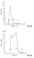
- Figure 5a-5f flow-time graphs. More specifically, Figure 5a shows the flow-time graph of the fluid to cylinder 6 starting with rod 37 screwed right down, i.e. with shutter 24 positioned close to shoulder 28 so that chamber 31 is of maximum volume, and assuming failure of hose 9,. At first, flow increases abruptly; and as soon as the instantaneous flow exceeds the set flow of valve assembly 8, this begins regulating. The operating fluid flows to cylinder 6 through calibrated choke 20.
- the delay time is also increased ( Figure 5g ) by providing, between head 25 and conduit 26, a brake ring 40, which provides for greatly increasing delay time, as shown by tg in the Figure 5g graph, which is obtained with rod 37 in the same position as in the Figure 5d graph.
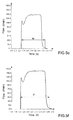
- Adjusting the delay time not only prevents pressure peaks in the feed pipe and non-isolated suspension cylinders, but also, and above all, prevents severe permanent overloading of the suspensions not affected by closure of the valve assembly, as shown in the Figure 6 graph, in which the pressures in the time periods indicated A and B are roughly comparable or at any rate differ only slightly, unlike the corresponding time periods A and B in the known solution graph in Figure 4 .
- the closing and adjusting device 35 is replaced with a device 45, which comprises an electric or servocontrolled linear actuator 44; and a unit 46 (shown schematically) for controlling linear actuator 45.
- Unit 46 comprises a number of selectors 47 which can be operated, e.g. by the driver of the trailer, to move shutter 24 manually into respective given axial positions, and so set different delay times.
- unit 46 comprises a block 48 for periodically or continually receiving signals proportional to the stress state and/or position of suspensions 5; and a setting block which moves shutter 24 automatically, in response to the signals received, to set the best delay times.
- closing shutter 24 in the opposite direction to the flow direction of the fluid to cylinder 6 provides for achieving a valve assembly which, as compared with known solutions in which the shutter closes in the fluid flow direction, is practically unaffected by variations in flow, so even major variations in flow have practically no effect on the set delay times.
- valve assembly 8 the set flow is determined solely by a diaphragm and therefore unrelated to the travel of shutter 24.
Landscapes
- Engineering & Computer Science (AREA)
- Mechanical Engineering (AREA)
- General Engineering & Computer Science (AREA)
- Vehicle Body Suspensions (AREA)
Applications Claiming Priority (1)
| Application Number | Priority Date | Filing Date | Title |
|---|---|---|---|
| ITTO2009A000417A IT1394896B1 (it) | 2009-06-03 | 2009-06-03 | Metodo per il controllo dell'alimentazione di un fluido operativo in pressione ad un cilindro idraulico di una sospensione e gruppo valvolare per attuare tale metodo |
Publications (2)
| Publication Number | Publication Date |
|---|---|
| EP2258570A1 true EP2258570A1 (de) | 2010-12-08 |
| EP2258570B1 EP2258570B1 (de) | 2012-05-09 |
Family
ID=41507980
Family Applications (1)
| Application Number | Title | Priority Date | Filing Date |
|---|---|---|---|
| EP10164808A Active EP2258570B1 (de) | 2009-06-03 | 2010-06-03 | Verfahren zur Steuerung des Fluiddruckes eines hydraulischen Federungszylinders und die Ventilanordnung zur Umsetzung des Verfahrens |
Country Status (4)
| Country | Link |
|---|---|
| EP (1) | EP2258570B1 (de) |
| AT (1) | ATE557199T1 (de) |
| CA (1) | CA2706160A1 (de) |
| IT (1) | IT1394896B1 (de) |
Cited By (1)
| Publication number | Priority date | Publication date | Assignee | Title |
|---|---|---|---|---|
| ITUB20161198A1 (it) * | 2016-03-01 | 2017-09-01 | Cometto Ind | Veicolo per il supporto, il trasporto ed il comando di un carico balistico |
Citations (4)
| Publication number | Priority date | Publication date | Assignee | Title |
|---|---|---|---|---|
| EP0443613A2 (de) * | 1990-02-23 | 1991-08-28 | Nissan Motor Company, Limited | Arbeitsfluidumkreis mit Leitungsdrucksteuerung für das Aktivaufhängungssystem eines Fahrzeugs |
| US5085460A (en) * | 1989-07-11 | 1992-02-04 | Nissan Motor Company, Limited | Working fluid circuit for automotive active suspension system with enhanced take-up characteristics upon initiation of operation |
| US6389341B1 (en) * | 2001-01-12 | 2002-05-14 | Davis Family Irrevocable Trust | Control system for a vehicle suspension |
| US20050225048A1 (en) * | 2003-03-12 | 2005-10-13 | Toyota Jidosha Kabushiki Kaisha | Vehicular suspension system |
-
2009
- 2009-06-03 IT ITTO2009A000417A patent/IT1394896B1/it active
-
2010
- 2010-06-01 CA CA2706160A patent/CA2706160A1/en not_active Abandoned
- 2010-06-03 AT AT10164808T patent/ATE557199T1/de active
- 2010-06-03 EP EP10164808A patent/EP2258570B1/de active Active
Patent Citations (4)
| Publication number | Priority date | Publication date | Assignee | Title |
|---|---|---|---|---|
| US5085460A (en) * | 1989-07-11 | 1992-02-04 | Nissan Motor Company, Limited | Working fluid circuit for automotive active suspension system with enhanced take-up characteristics upon initiation of operation |
| EP0443613A2 (de) * | 1990-02-23 | 1991-08-28 | Nissan Motor Company, Limited | Arbeitsfluidumkreis mit Leitungsdrucksteuerung für das Aktivaufhängungssystem eines Fahrzeugs |
| US6389341B1 (en) * | 2001-01-12 | 2002-05-14 | Davis Family Irrevocable Trust | Control system for a vehicle suspension |
| US20050225048A1 (en) * | 2003-03-12 | 2005-10-13 | Toyota Jidosha Kabushiki Kaisha | Vehicular suspension system |
Cited By (2)
| Publication number | Priority date | Publication date | Assignee | Title |
|---|---|---|---|---|
| ITUB20161198A1 (it) * | 2016-03-01 | 2017-09-01 | Cometto Ind | Veicolo per il supporto, il trasporto ed il comando di un carico balistico |
| EP3214401A1 (de) | 2016-03-01 | 2017-09-06 | Industrie Cometto S.p.A. | Fahrzeug zum stützen, transportieren und ansteuern einer ballistischen last |
Also Published As
| Publication number | Publication date |
|---|---|
| ATE557199T1 (de) | 2012-05-15 |
| CA2706160A1 (en) | 2010-12-03 |
| ITTO20090417A1 (it) | 2010-12-04 |
| IT1394896B1 (it) | 2012-07-20 |
| EP2258570B1 (de) | 2012-05-09 |
Similar Documents
| Publication | Publication Date | Title |
|---|---|---|
| US11306798B2 (en) | Position sensitive suspension damping with an active valve | |
| EP2483574B1 (de) | Einstellbarer stossdämpfer | |
| US20170184174A1 (en) | Bypass for a suspension damper | |
| CN101796307B (zh) | 一种尤其用于机械装置的液压驱动器及其控制方法 | |
| US7581487B2 (en) | Pressure-compensating directional control valve | |
| WO2021076813A9 (en) | An active valve system having more than one stage | |
| US20230226873A1 (en) | Mechanical bypass of a valve body | |
| CN103883666B (zh) | 用于半活动振动阻尼器的阻尼阀配置 | |
| EP2258570B1 (de) | Verfahren zur Steuerung des Fluiddruckes eines hydraulischen Federungszylinders und die Ventilanordnung zur Umsetzung des Verfahrens | |
| DE102015225057A1 (de) | Verfahren zum Betreiben einer elektronisch schlupfregelbaren Fremdkraftbremsanlage und Elektronisch schlupfregelbare Fremdkraftbremsanlage | |
| CN104797472B (zh) | 主缸以及主缸装置 | |
| EP2739513B1 (de) | Verfahren zur optimierung der druckstellgenauigkeit | |
| WO2009077232A1 (de) | Verfahren zur steuerung eines kraftfahrzeug-fahrwerks | |
| CN103978864B (zh) | 一种双胎提升桥液压举升控制系统 | |
| CN204213434U (zh) | 一种活塞式减压阀 | |
| EP3401177B1 (de) | Anordnung zur steuerung eines anhängerbremsventils, zur kopplung mit einem bremssystem eines anhängerfahrzeugs. | |
| CN105065360A (zh) | 一种恒功率控制装置及其压力变量控制方法 | |
| CN204387193U (zh) | 阻尼器总成 | |
| CN204387191U (zh) | 车用减震器阻尼器机构 | |
| US20210323514A1 (en) | Electrohydraulic brake apparatus | |
| CN108317280B (zh) | 一种拖拉机用动力换向阀 | |
| US9115850B2 (en) | Priority valve assembly and method for operating a priority valve assembly | |
| DE2212518A1 (de) | Ventil zur Bremskraftsteuerung in einer Fahrzeugbremsanlage mit Antiblockiersystem | |
| KR20120101685A (ko) | 가변 변위 펌프 및 릴리프 밸브를 포함하는 유압 어셈블리 | |
| EP3592619B1 (de) | Bremssystemventilanordnung und bremssattelkörper mit dieser anordnung |
Legal Events
| Date | Code | Title | Description |
|---|---|---|---|
| PUAI | Public reference made under article 153(3) epc to a published international application that has entered the european phase |
Free format text: ORIGINAL CODE: 0009012 |
|
| AK | Designated contracting states |
Kind code of ref document: A1 Designated state(s): AL AT BE BG CH CY CZ DE DK EE ES FI FR GB GR HR HU IE IS IT LI LT LU LV MC MK MT NL NO PL PT RO SE SI SK SM TR |
|
| AX | Request for extension of the european patent |
Extension state: BA ME RS |
|
| RTI1 | Title (correction) |
Free format text: METHOD OF CONTROLLING PRESSURIZED OPERATING FLUID FEED TO A HYDRAULIC SUSPENSION CYLINDER, AND VALVE ASSEMBLY IMPLEMENTING SUCH A METHOD |
|
| 17P | Request for examination filed |
Effective date: 20110608 |
|
| REG | Reference to a national code |
Ref country code: DE Ref legal event code: R079 Ref document number: 602010001379 Country of ref document: DE Free format text: PREVIOUS MAIN CLASS: B60G0017018500 Ipc: F16F0009440000 |
|
| GRAP | Despatch of communication of intention to grant a patent |
Free format text: ORIGINAL CODE: EPIDOSNIGR1 |
|
| RIC1 | Information provided on ipc code assigned before grant |
Ipc: B60G 21/067 20060101ALI20111006BHEP Ipc: B60G 17/0185 20060101ALI20111006BHEP Ipc: F16F 5/00 20060101ALI20111006BHEP Ipc: F16F 9/44 20060101AFI20111006BHEP |
|
| GRAS | Grant fee paid |
Free format text: ORIGINAL CODE: EPIDOSNIGR3 |
|
| GRAA | (expected) grant |
Free format text: ORIGINAL CODE: 0009210 |
|
| AK | Designated contracting states |
Kind code of ref document: B1 Designated state(s): AL AT BE BG CH CY CZ DE DK EE ES FI FR GB GR HR HU IE IS IT LI LT LU LV MC MK MT NL NO PL PT RO SE SI SK SM TR |
|
| REG | Reference to a national code |
Ref country code: GB Ref legal event code: FG4D |
|
| REG | Reference to a national code |
Ref country code: AT Ref legal event code: REF Ref document number: 557199 Country of ref document: AT Kind code of ref document: T Effective date: 20120515 Ref country code: CH Ref legal event code: EP |
|
| REG | Reference to a national code |
Ref country code: IE Ref legal event code: FG4D |
|
| REG | Reference to a national code |
Ref country code: DE Ref legal event code: R096 Ref document number: 602010001379 Country of ref document: DE Effective date: 20120705 |
|
| REG | Reference to a national code |
Ref country code: NL Ref legal event code: T3 |
|
| REG | Reference to a national code |
Ref country code: LT Ref legal event code: MG4D Effective date: 20120509 |
|
| PG25 | Lapsed in a contracting state [announced via postgrant information from national office to epo] |
Ref country code: PL Free format text: LAPSE BECAUSE OF FAILURE TO SUBMIT A TRANSLATION OF THE DESCRIPTION OR TO PAY THE FEE WITHIN THE PRESCRIBED TIME-LIMIT Effective date: 20120509 Ref country code: CY Free format text: LAPSE BECAUSE OF FAILURE TO SUBMIT A TRANSLATION OF THE DESCRIPTION OR TO PAY THE FEE WITHIN THE PRESCRIBED TIME-LIMIT Effective date: 20120509 Ref country code: SE Free format text: LAPSE BECAUSE OF FAILURE TO SUBMIT A TRANSLATION OF THE DESCRIPTION OR TO PAY THE FEE WITHIN THE PRESCRIBED TIME-LIMIT Effective date: 20120509 Ref country code: LT Free format text: LAPSE BECAUSE OF FAILURE TO SUBMIT A TRANSLATION OF THE DESCRIPTION OR TO PAY THE FEE WITHIN THE PRESCRIBED TIME-LIMIT Effective date: 20120509 Ref country code: IS Free format text: LAPSE BECAUSE OF FAILURE TO SUBMIT A TRANSLATION OF THE DESCRIPTION OR TO PAY THE FEE WITHIN THE PRESCRIBED TIME-LIMIT Effective date: 20120909 Ref country code: FI Free format text: LAPSE BECAUSE OF FAILURE TO SUBMIT A TRANSLATION OF THE DESCRIPTION OR TO PAY THE FEE WITHIN THE PRESCRIBED TIME-LIMIT Effective date: 20120509 Ref country code: NO Free format text: LAPSE BECAUSE OF FAILURE TO SUBMIT A TRANSLATION OF THE DESCRIPTION OR TO PAY THE FEE WITHIN THE PRESCRIBED TIME-LIMIT Effective date: 20120809 |
|
| REG | Reference to a national code |
Ref country code: AT Ref legal event code: MK05 Ref document number: 557199 Country of ref document: AT Kind code of ref document: T Effective date: 20120509 |
|
| PG25 | Lapsed in a contracting state [announced via postgrant information from national office to epo] |
Ref country code: LV Free format text: LAPSE BECAUSE OF FAILURE TO SUBMIT A TRANSLATION OF THE DESCRIPTION OR TO PAY THE FEE WITHIN THE PRESCRIBED TIME-LIMIT Effective date: 20120509 Ref country code: PT Free format text: LAPSE BECAUSE OF FAILURE TO SUBMIT A TRANSLATION OF THE DESCRIPTION OR TO PAY THE FEE WITHIN THE PRESCRIBED TIME-LIMIT Effective date: 20120910 Ref country code: GR Free format text: LAPSE BECAUSE OF FAILURE TO SUBMIT A TRANSLATION OF THE DESCRIPTION OR TO PAY THE FEE WITHIN THE PRESCRIBED TIME-LIMIT Effective date: 20120810 Ref country code: HR Free format text: LAPSE BECAUSE OF FAILURE TO SUBMIT A TRANSLATION OF THE DESCRIPTION OR TO PAY THE FEE WITHIN THE PRESCRIBED TIME-LIMIT Effective date: 20120509 Ref country code: SI Free format text: LAPSE BECAUSE OF FAILURE TO SUBMIT A TRANSLATION OF THE DESCRIPTION OR TO PAY THE FEE WITHIN THE PRESCRIBED TIME-LIMIT Effective date: 20120509 |
|
| PG25 | Lapsed in a contracting state [announced via postgrant information from national office to epo] |
Ref country code: CZ Free format text: LAPSE BECAUSE OF FAILURE TO SUBMIT A TRANSLATION OF THE DESCRIPTION OR TO PAY THE FEE WITHIN THE PRESCRIBED TIME-LIMIT Effective date: 20120509 Ref country code: EE Free format text: LAPSE BECAUSE OF FAILURE TO SUBMIT A TRANSLATION OF THE DESCRIPTION OR TO PAY THE FEE WITHIN THE PRESCRIBED TIME-LIMIT Effective date: 20120509 Ref country code: RO Free format text: LAPSE BECAUSE OF FAILURE TO SUBMIT A TRANSLATION OF THE DESCRIPTION OR TO PAY THE FEE WITHIN THE PRESCRIBED TIME-LIMIT Effective date: 20120509 Ref country code: SK Free format text: LAPSE BECAUSE OF FAILURE TO SUBMIT A TRANSLATION OF THE DESCRIPTION OR TO PAY THE FEE WITHIN THE PRESCRIBED TIME-LIMIT Effective date: 20120509 Ref country code: MC Free format text: LAPSE BECAUSE OF NON-PAYMENT OF DUE FEES Effective date: 20120630 Ref country code: AT Free format text: LAPSE BECAUSE OF FAILURE TO SUBMIT A TRANSLATION OF THE DESCRIPTION OR TO PAY THE FEE WITHIN THE PRESCRIBED TIME-LIMIT Effective date: 20120509 Ref country code: DK Free format text: LAPSE BECAUSE OF FAILURE TO SUBMIT A TRANSLATION OF THE DESCRIPTION OR TO PAY THE FEE WITHIN THE PRESCRIBED TIME-LIMIT Effective date: 20120509 |
|
| PG25 | Lapsed in a contracting state [announced via postgrant information from national office to epo] |
Ref country code: MK Free format text: LAPSE BECAUSE OF FAILURE TO SUBMIT A TRANSLATION OF THE DESCRIPTION OR TO PAY THE FEE WITHIN THE PRESCRIBED TIME-LIMIT Effective date: 20120509 Ref country code: IT Free format text: LAPSE BECAUSE OF FAILURE TO SUBMIT A TRANSLATION OF THE DESCRIPTION OR TO PAY THE FEE WITHIN THE PRESCRIBED TIME-LIMIT Effective date: 20120509 |
|
| PLBE | No opposition filed within time limit |
Free format text: ORIGINAL CODE: 0009261 |
|
| STAA | Information on the status of an ep patent application or granted ep patent |
Free format text: STATUS: NO OPPOSITION FILED WITHIN TIME LIMIT |
|
| REG | Reference to a national code |
Ref country code: IE Ref legal event code: MM4A |
|
| 26N | No opposition filed |
Effective date: 20130212 |
|
| PG25 | Lapsed in a contracting state [announced via postgrant information from national office to epo] |
Ref country code: ES Free format text: LAPSE BECAUSE OF FAILURE TO SUBMIT A TRANSLATION OF THE DESCRIPTION OR TO PAY THE FEE WITHIN THE PRESCRIBED TIME-LIMIT Effective date: 20120820 Ref country code: IE Free format text: LAPSE BECAUSE OF NON-PAYMENT OF DUE FEES Effective date: 20120603 |
|
| REG | Reference to a national code |
Ref country code: DE Ref legal event code: R097 Ref document number: 602010001379 Country of ref document: DE Effective date: 20130212 |
|
| PG25 | Lapsed in a contracting state [announced via postgrant information from national office to epo] |
Ref country code: MT Free format text: LAPSE BECAUSE OF FAILURE TO SUBMIT A TRANSLATION OF THE DESCRIPTION OR TO PAY THE FEE WITHIN THE PRESCRIBED TIME-LIMIT Effective date: 20120509 Ref country code: BG Free format text: LAPSE BECAUSE OF FAILURE TO SUBMIT A TRANSLATION OF THE DESCRIPTION OR TO PAY THE FEE WITHIN THE PRESCRIBED TIME-LIMIT Effective date: 20120809 |
|
| PG25 | Lapsed in a contracting state [announced via postgrant information from national office to epo] |
Ref country code: AL Free format text: LAPSE BECAUSE OF FAILURE TO SUBMIT A TRANSLATION OF THE DESCRIPTION OR TO PAY THE FEE WITHIN THE PRESCRIBED TIME-LIMIT Effective date: 20120509 |
|
| PG25 | Lapsed in a contracting state [announced via postgrant information from national office to epo] |
Ref country code: SM Free format text: LAPSE BECAUSE OF FAILURE TO SUBMIT A TRANSLATION OF THE DESCRIPTION OR TO PAY THE FEE WITHIN THE PRESCRIBED TIME-LIMIT Effective date: 20120509 |
|
| PG25 | Lapsed in a contracting state [announced via postgrant information from national office to epo] |
Ref country code: HU Free format text: LAPSE BECAUSE OF FAILURE TO SUBMIT A TRANSLATION OF THE DESCRIPTION OR TO PAY THE FEE WITHIN THE PRESCRIBED TIME-LIMIT Effective date: 20100603 |
|
| REG | Reference to a national code |
Ref country code: CH Ref legal event code: PL |
|
| GBPC | Gb: european patent ceased through non-payment of renewal fee |
Effective date: 20140603 |
|
| PG25 | Lapsed in a contracting state [announced via postgrant information from national office to epo] |
Ref country code: LI Free format text: LAPSE BECAUSE OF NON-PAYMENT OF DUE FEES Effective date: 20140630 Ref country code: CH Free format text: LAPSE BECAUSE OF NON-PAYMENT OF DUE FEES Effective date: 20140630 |
|
| PG25 | Lapsed in a contracting state [announced via postgrant information from national office to epo] |
Ref country code: GB Free format text: LAPSE BECAUSE OF NON-PAYMENT OF DUE FEES Effective date: 20140603 |
|
| REG | Reference to a national code |
Ref country code: FR Ref legal event code: PLFP Year of fee payment: 7 |
|
| REG | Reference to a national code |
Ref country code: FR Ref legal event code: PLFP Year of fee payment: 8 |
|
| REG | Reference to a national code |
Ref country code: FR Ref legal event code: PLFP Year of fee payment: 9 |
|
| REG | Reference to a national code |
Ref country code: DE Ref legal event code: R082 Ref document number: 602010001379 Country of ref document: DE Representative=s name: SPARING - ROEHL - HENSELER, DE Ref country code: DE Ref legal event code: R081 Ref document number: 602010001379 Country of ref document: DE Owner name: COMETTO S.P.A., IT Free format text: FORMER OWNER: INDUSTRIE COMETTO S.P.A., BORGO SAN DALMAZZO, IT |
|
| REG | Reference to a national code |
Ref country code: NL Ref legal event code: HC Owner name: COMETTO S.P.A.; IT Free format text: DETAILS ASSIGNMENT: CHANGE OF OWNER(S), CHANGE OF OWNER(S) NAME; FORMER OWNER NAME: INDUSTRIE COMETTO S.P.A. Effective date: 20191108 |
|
| REG | Reference to a national code |
Ref country code: LU Ref legal event code: HC Owner name: COMETTO S.P.A.; IT Free format text: FORMER OWNER: INDUSTRIE COMETTO S.P.A. Effective date: 20191111 |
|
| REG | Reference to a national code |
Ref country code: BE Ref legal event code: HC Owner name: COMETTO S.P.A.; IT Free format text: DETAILS ASSIGNMENT: CHANGE OF OWNER(S), CHANGEMENT DE NOM DU PROPRIETAIRE; FORMER OWNER NAME: INDUSTRIE COMETTO S.P.A. Effective date: 20200214 |
|
| PGFP | Annual fee paid to national office [announced via postgrant information from national office to epo] |
Ref country code: NL Payment date: 20230626 Year of fee payment: 14 Ref country code: FR Payment date: 20230622 Year of fee payment: 14 Ref country code: DE Payment date: 20230627 Year of fee payment: 14 |
|
| PGFP | Annual fee paid to national office [announced via postgrant information from national office to epo] |
Ref country code: TR Payment date: 20230526 Year of fee payment: 14 Ref country code: LU Payment date: 20230626 Year of fee payment: 14 |
|
| PGFP | Annual fee paid to national office [announced via postgrant information from national office to epo] |
Ref country code: BE Payment date: 20230626 Year of fee payment: 14 |