EP2256696A1 - Quality control apparatus and control method of the same, and recording medium recorded with quality control program - Google Patents
Quality control apparatus and control method of the same, and recording medium recorded with quality control program Download PDFInfo
- Publication number
- EP2256696A1 EP2256696A1 EP10008746A EP10008746A EP2256696A1 EP 2256696 A1 EP2256696 A1 EP 2256696A1 EP 10008746 A EP10008746 A EP 10008746A EP 10008746 A EP10008746 A EP 10008746A EP 2256696 A1 EP2256696 A1 EP 2256696A1
- Authority
- EP
- European Patent Office
- Prior art keywords
- control
- data
- value
- intermediate characteristic
- module
- Prior art date
- Legal status (The legal status is an assumption and is not a legal conclusion. Google has not performed a legal analysis and makes no representation as to the accuracy of the status listed.)
- Granted
Links
Images






Classifications
-
- G—PHYSICS
- G06—COMPUTING OR CALCULATING; COUNTING
- G06Q—INFORMATION AND COMMUNICATION TECHNOLOGY [ICT] SPECIALLY ADAPTED FOR ADMINISTRATIVE, COMMERCIAL, FINANCIAL, MANAGERIAL OR SUPERVISORY PURPOSES; SYSTEMS OR METHODS SPECIALLY ADAPTED FOR ADMINISTRATIVE, COMMERCIAL, FINANCIAL, MANAGERIAL OR SUPERVISORY PURPOSES, NOT OTHERWISE PROVIDED FOR
- G06Q10/00—Administration; Management
- G06Q10/06—Resources, workflows, human or project management; Enterprise or organisation planning; Enterprise or organisation modelling
-
- G—PHYSICS
- G07—CHECKING-DEVICES
- G07C—TIME OR ATTENDANCE REGISTERS; REGISTERING OR INDICATING THE WORKING OF MACHINES; GENERATING RANDOM NUMBERS; VOTING OR LOTTERY APPARATUS; ARRANGEMENTS, SYSTEMS OR APPARATUS FOR CHECKING NOT PROVIDED FOR ELSEWHERE
- G07C3/00—Registering or indicating the condition or the working of machines or other apparatus, other than vehicles
- G07C3/14—Quality control systems
-
- G—PHYSICS
- G05—CONTROLLING; REGULATING
- G05B—CONTROL OR REGULATING SYSTEMS IN GENERAL; FUNCTIONAL ELEMENTS OF SUCH SYSTEMS; MONITORING OR TESTING ARRANGEMENTS FOR SUCH SYSTEMS OR ELEMENTS
- G05B2219/00—Program-control systems
- G05B2219/30—Nc systems
- G05B2219/32—Operator till task planning
- G05B2219/32196—Store audit, history of inspection, control and workpiece data into database
-
- G—PHYSICS
- G07—CHECKING-DEVICES
- G07C—TIME OR ATTENDANCE REGISTERS; REGISTERING OR INDICATING THE WORKING OF MACHINES; GENERATING RANDOM NUMBERS; VOTING OR LOTTERY APPARATUS; ARRANGEMENTS, SYSTEMS OR APPARATUS FOR CHECKING NOT PROVIDED FOR ELSEWHERE
- G07C3/00—Registering or indicating the condition or the working of machines or other apparatus, other than vehicles
-
- Y—GENERAL TAGGING OF NEW TECHNOLOGICAL DEVELOPMENTS; GENERAL TAGGING OF CROSS-SECTIONAL TECHNOLOGIES SPANNING OVER SEVERAL SECTIONS OF THE IPC; TECHNICAL SUBJECTS COVERED BY FORMER USPC CROSS-REFERENCE ART COLLECTIONS [XRACs] AND DIGESTS
- Y02—TECHNOLOGIES OR APPLICATIONS FOR MITIGATION OR ADAPTATION AGAINST CLIMATE CHANGE
- Y02P—CLIMATE CHANGE MITIGATION TECHNOLOGIES IN THE PRODUCTION OR PROCESSING OF GOODS
- Y02P90/00—Enabling technologies with a potential contribution to greenhouse gas [GHG] emissions mitigation
- Y02P90/02—Total factory control, e.g. smart factories, flexible manufacturing systems [FMS] or integrated manufacturing systems [IMS]
Definitions
- the present invention relates to a quality control apparatus for controlling a manufacturing process and a control method of the same, a quality control program, and a recording medium recorded with the program for manufacturing products of predetermined quality.
- a management method is proposed in which identification codes such as bar codes are assigned to intermediate products for products and to bases on which the intermediate product is placed. Furthermore, in order to realize traceability, an identification method is proposed in which intermediate products are identified in order of the intermediate products to be put in each of manufacturing process steps.
- An obj ect is to provide a quality control apparatus which associates various items of data with each other that are collected at different process steps in production sites where traceability is difficult to do.
- a quality control apparatus which controls a manufacturing process in order to manufacture products of predetermined quality, the apparatus including:
- An intermediate product measured by a certain device is to be measured by the subsequent device at the time after dead time has roughly elapsed from when the intermediate product was measured. Therefore, the time measured by each of the measuring devices or the time collected by each of the measuring devices can be roughly associated by the dead time.
- the associating module since the collected measurement data is associated with the measured time or collected time, the associating module roughly associates the measured time or collected time by the dead time generated between the measuring devices, and therefore the measurement data of the measuring devices can be associated with each other.
- the dead time is used only by the associating module, and does not influence the data stored in the storing module even though the dead time is changed. Therefore, the dead time can be changed easily.
- the associating module associates given numbers of items of measurement data of the multiple measuring devices with each other.
- a set formed of the given number of items of measurement data is formed in each of the measuring devices, and the sets in the multiple measuring devices are associated with each other. Therefore, since the number of items of measurement data included in the individual associated sets is constant, the accuracy of statistics of each set can be nearly matched.
- the set is formed based on the number of measurements, not on a time period measured by the measuring device, and thus the individual sets can be properly associated with each other even though a certain process step in a manufacturing process is stopped for a long time and then started, for example.
- the associating module stops association of the improper measurement data with the measurement data that is the measurement data measured by the other measuring device and corresponds to the improper measurement data.
- the case where the measurement value is an outlier that is greatly deviated from a normal value the case where a device reifies the same intermediate product because of failed measurement
- the case where the intermediate product determined as out-of-specification in intermediate inspection is put back to the process step on the upstream side
- the improper measurement data causes the reduced accuracy in conducting statistical processes.
- the accuracy of the statistical processes can be prevented from being reduced.
- the associating module stops association of measurement data relating to the intermediate product of the measuring device on an upstream side of the process step with measurement data relating to the intermediate product of the measuring device at the process step and on a downstream side thereof.
- the associating module stops association of measurement data of the measuring device on a downstream side of the process step with measurement data relating to the intermediate product of the measuring device at the process step and on an upstream side thereof.
- a quality control apparatus is a quality control apparatus which controls a manufacturing process in order to manufacture products of predetermined quality, the apparatus including:
- the intermediate characteristic measuring device inspects the intermediate characteristics of the intermediate product in the middle of production, and determines whether the intermediate product is passed or failed based on the intermediate characteristic specification limit. Since the defective is removed in the middle of production by using the intermediate characteristic measuring device, unnecessary production time for the defective can be eliminated and the intervals between control feedback loops can be reduced.
- the specification limit generating module switches the intermediate characteristic specification limit based on the final characteristic of the completed product, the intermediate characteristic specification limit can be automatically adjusted even though various parameters in the manufacturing process are varied.
- the specification limit generating module generates the intermediate characteristic specification limit based on a differential between a mean value of the data distribution of the final characteristic data and the final characteristic specification limit. Moreover, desirably, the specification limit generating module generates the intermediate characteristic specification limit so that a ratio of a differential between a mean value of a data distribution of the intermediate characteristic data stored in the storing module and the intermediate characteristic specification limit with respect to the differential between the mean value of the data distribution of the final characteristic data and the final characteristic specification limit is a ratio of a variation value of the data distribution of the intermediate characteristic data with respect to a variation value of the data distribution of the final characteristic data.
- variation value of the data distribution indicates the degree of variations in the data distribution.
- standard deviation, variance, and half width are named.
- the specification limit generating module further generates the intermediate characteristic specification limit based on a safety factor.
- the intermediate product can be efficiently removed based on the intermediate characteristic specification limit.
- the safety factor can be also set based on empirical rules, but desirably, it is calculated based on discard cost when the completed product is removed based on the final characteristic specification limit and discard cost when the intermediate product is removed based on the intermediate characteristic specification limit.
- the storing module stores the intermediate characteristic data and the final characteristic data along with measured time or collected time
- the quality control apparatus further includes:
- the specification limit generating module generates a subsequent specification limit by using the intermediate characteristic data and the final characteristic data collected by the storing module after a given time period has elapsed from when the specification limit setting control module controlled the intermediate characteristic measuring device.
- the specification limit setting control module controlled the intermediate characteristic measuring device.
- a quality control apparatus is a quality control apparatus which controls a control target device disposed in a manufacturing process in order to manufacture products of predetermined quality, the apparatus including:
- various amounts can be used such as the mean value and the variation value.
- a variation in the data distribution of the intermediate characteristic data is estimated when the set value of the control value is switched, and the number of defectives to be generated is estimated. Then, the switching amount for the set value of the control value is decided so that the estimated number of defectives is the minimum, and the set value of the control value of the control target device is switched.
- control over the control target device is switched so that the intermediate product is inspected in the middle of production to decrease the number of the defectives in the intermediate products, the intervals between control feedback loops can be reduced. Furthermore, since a variation in the data distribution is estimated to consider variations in data, the number of defectives to be generated can be more accurately estimated.
- the quality control apparatus further includes an impact storingmodule which stores an impact that indicates a degree of a variation in the data distribution of the intermediate characteristic data with respect to a change in a mean value of the control data, wherein the intermediate characteristic estimating module estimates the variation in the data distribution of the intermediate characteristic data based on the switching amount for the set value of the control value stored in the storing module and the impact stored in the impact storing module, and the switching amount deciding module decides a switching amount for the set value of the control value so that the number of defectives estimated by the defective number estimating module is the minimum.
- the correlation between a change in the mean value of the control data and a variation in the data distribution of the intermediate characteristic data is determined.
- the variation in the data distribution of the intermediate characteristic data can be more accurately estimated, and the number of defectives to be generated can be more accurately estimated.
- the quality control apparatus further includes an impact creating module which creates the impact and stores it in the impact storing module when a difference more than a given amount is generated between the data distribution of the intermediate characteristic data corresponding to a switching amount for the set value of the control value decided by the switching amount deciding module and the distribution of the intermediate characteristic data collected by the storing module after the control switching module switches control.
- the impact can be automatically adjusted even though the variation is generated in the manufacturing process.
- a variation in the data distribution of the intermediate characteristic data can be more accurately estimated, and products of proper quality can be manufactured.
- the storing module further collects and stores final characteristic data of a completed product measured by a final characteristic measuring device
- the quality control apparatus further includes:
- the storing module stores the control data and the intermediate characteristic data along with measured time or collected time
- the quality control apparatus further includes:
- the intermediate characteristic estimating module estimates a subsequent data distribution of the intermediate characteristic data by using the intermediate characteristic data collected by the storing module after a given time period has elapsed from when the control switching module switched control. In this case, since data in the middle of switching the control is not used, further accurate control is possible.
- a control method of a quality control apparatus is a control method of a quality control apparatus which controls a manufacturing process in order to manufacture products of predetermined quality, the apparatus including:
- the associating module since the collected measurement data is associated with the measured time or collected time, the associating module roughly associates the measured time or collected time by the dead time generated between the measuring devices, and thus the measurement data of the measuring devices can be associated with each other. Furthermore, the dead time is used only at the association step, and the data stored in the storing module is not influenced even though dead time is changed. Therefore, the dead time can be changed easi ly.
- a control method of a quality control apparatus is a control method of a quality control apparatus which controls a manufacturing process in order to manufacture products of predetermined quality, the apparatus including:
- the intermediate characteristic specification limit since the intermediate characteristic specification limit is switched based on the final characteristic of the completed product at the specification limit generating step, the intermediate characteristic specification limit can be automatically adjusted even though various parameters are changed in the manufacturing process.
- a control method of a quality control apparatus is a control method of a quality control apparatus which controls a control target device disposed in a manufacturing process in order to manufacture products of predetermined quality, the apparatus including:
- the variation in the data distribution of the intermediate characteristic data is estimated when the set value of the control value is switched, and the number of defectives to be generated is estimated. Then, a switching amount for the set value of the control value is decided so that the estimated number of defectives is the minimum, and the set value of the control value of the control target device is switched. Therefore, since control over the control target device is switched so that the intermediate product is inspected in the middle of production to decrease the number of the defectives in the intermediate products, the intervals between control feedback loops can be reduced. Moreover, since the variation in the data distribution is estimated to also consider variations in data, the number of defectives to be generated can be more accurately estimated.
- the individual modules in the quality control apparatus can be run on a computer by a quality control program.
- the quality control program is stored in a computer readable recording medium, and thus the quality control program can be executed on a given computer.
- the quality control apparatus exerts an advantage that since the collected measurement data is associated with the measured time or collected time, the associating module roughly associates the measured time or collected time by the dead time generated between the measuring devices and thus the measurement data of the measuring devices can be associated with each other.
- Fig. 1 shows the schematic configuration of a quality control system which controls qualityof products manufacturedof certain materials.
- a quality control system 1 is configured to have control target devices (measuring devices) 3 and 4 to be control targets, an intermediate characteristic measuring device (measuring device) 5 which inspects the intermediate characteristics to be the characteristics of intermediate products in the middle of production, a final characteristic measuring device (measuring device) 6 which inspects the final characteristics of manufactured products, and a quality control apparatus 10 which collects data from the various devices 3 to 6 to control the control target devices 3 and 4 based on the collected data, and switches specification limits in the intermediate characteristic measuring device 5.
- a work 2 undergoes various process steps to manufacture a product 7.
- the work is considered to be manufactured as follows. More specifically, the first and second control target devices 3 and 4 sequentially perform their processes to the work 2. After that, the intermediate characteristic measuring device 5 performs an inspection process for the intermediate characteristics, and the other devices perform various processes. Then, the final characteristic measuring device 6 performs an inspection process for final characteristics.
- Each of the control target devices 3 and 4 acquires the set values for the control values from the quality control apparatus 10, and operates based on the acquired set values. Furthermore, each of the control target devices 3 and 4 actually measures the control values, and sends the measurement values measured to the quality control apparatus 10.
- a control target device is a heater
- the control values are numeric values showing temperatures such as temperatures, voltages and resistances corresponding to the temperatures.
- the intermediate characteristic measuring device 5 acquires the specification limits from the quality control apparatus 10, and inspects the intermediate characteristics of the work 2 (intermediate product) based on the acquired specification limits. Moreover, the intermediate characteristic measuring device 5 sends the inspected intermediate characteristics to the quality control apparatus 10.
- An intermediate product determined as being out-of-specification by the intermediate characteristic measuring device 5 is generally removed right after its intermediate characteristics are inspected.
- an intermediate product determined as out-of-specification is likely to be easily turned to be acceptable by again being processed by the second control target device 4, that intermediate product can be put back to the process steps done by the second control target device 4.
- the intermediate product is difficult to be removed right after its intermediate characteristics are inspected because of the system configuration and the device structure, it is fine to remove the intermediate product at the subsequent process steps.
- the final characteristic measuring device 6 inspects the final characteristics of the completed product based on the predetermined specification limits. At this time, the completed product determined as out-of-specification is discarded, repaired, or disassembled and reused, whereas the completed product determined as acceptable is shipped as a product 7. Besides, the final characteristic measuring device 6 sends the inspected final characteristics to the quality control apparatus 10.
- a time lag is generated at the time when the individual devices 3 to 6 process a certain work 2. This time lag is called 'dead time'.
- dead time Td1 is generatedbetween the time when the first control target device 3 starts its process and the time when the second control target device 4 starts its process.
- Dead time Td2 is generated between the time when the second control target device 4 starts its process and the time when the intermediate characteristic measuring device 5 starts its process.
- Dead time Td3 is generated between the time when the intermediate characteristic measuring device 5 starts its process and the time when the final characteristic measuring device 6 starts its process.
- control target devices the intermediate characteristic measuring devices, and the final characteristic measuring devices are acceptable.
- all the devices relating to production are not necessarily the control target devices.
- a single device includes multiple control target devices.
- the quality control apparatus 10 is configured to have a data storing part (storing module) 11, a scheduler (associating module) 12, a specification limit generating part (a specification limit generating module and a specification limit setting control module) 13, an impact creating part (impact creating module) 14, an impact storage DB (data base) (impact storing module) 15, an estimating part 16, and a control instructing part (control switching module) 17.
- the control apparatus 10 is configured of a PC (Personal Computer) based computer, for example.
- the data storing part 11 sequentially acquires the measurement values of the control values from each of the control target devices 3 and 4, stores the acquired measurement values andacquiredtime (collected time) as control data, sequentially acquires the intermediate characteristic data from the intermediate characteristic measuring device 5, stores the acquired intermediate characteristic data and acquired time as intermediate characteristic data, sequentially acquires the final characteristic data from the final characteristic measuring device 6, and stores the acquired final characteristic data and acquired time as final characteristic data.
- the data storing part 11 notifies the scheduler 12 that the data storing part 11 starts acquiring data. Furthermore, it is fine that the individual devices 3 to 6 store measured time instead of the acquired time.
- the scheduler 12 associates data that is considered to belong to the same work 2 with each other among the control data, the intermediate characteristic data, and the final characteristic data stored in the data storing part 11 by using the acquired time and the dead time for each item of data. Moreover, the scheduler 12 decides the timing to switch the set values of the control values for controlling the control target devices 3 and 4, and the timing to switch the specification limits of the intermediate characteristics of the intermediate characteristic measuring device 5.
- association is conducted based on the individual works 2, or a given number of the works 2, or the works 2 processed during a given time period.
- a series of items of data included in the given number or given time period is called a set.
- the specification limit generating part 13 reads a set of the intermediate characteristic data and a set of the final characteristic data associated by the scheduler 12 out of the data storing part 11, and generates the specification limits of the intermediate characteristics based on the read out sets. Furthermore, the specification limit generating part 13 sends the generated specification limits to the intermediate characteristic measuring device 5 based on the timing decided by the scheduler 12. Moreover, it is fine that the specification limit generating part 13 generates the specification limits only when the specification limits of the intermediate characteristics of the intermediate characteristic measuring device 5 need to be switched. Besides, the specification limit generating part 13 generates the estimated values of the specification limits of the intermediate characteristics, and sends the generated estimated values to the estimating part 16.
- the impact creatingpart 14 creates an impact in accordance with the request of the estimating part 16.
- an impact shows how the intermediate characteristics are varied when the control values are switched.
- the impact creating part 14 sends the created impact to the estimating part 16 as well as stores it in the impact storage DB 15. More specifically, the impact creating part 14 reads a set of the control data and a set of the intermediate characteristic data associated by the scheduler 12 out of the data storing part 11, and calculates a variation in the mean value and/or variance of the intermediate characteristic data with respect to a change in the mean value of the control data based on the read sets for normalization to create an impact.
- given indicators showing the extent of variations can be used. For example, standard deviation and half width can be used.
- the estimating part 16 reads a set of the intermediate characteristic data associated by the scheduler 12 out of the data storing part 11, and estimates the mean value of the intermediate characteristics and/or the variation in variance from the read set by using the impact read out of the impact storage DB 15. Besides, the estimating part 16 estimates the number of defectives when the distribution of the intermediate characteristics is changed by the estimated value of the variation, and evaluates by the sum of each of the number of defectives. Then, it determines the switching amount for the set value of the control value when the number of defectives is the minimum, and sends it to the control instructing part 17.
- the control instructing part 17 switches the set value of the control value based on the switching amount for the set value of the control value determined by the estimating part 16. Furthermore, the control instructing part 17 sends the switched set value as a control instruction to the control target devices 3 and 4 based on the timing decided by the scheduler 12. Therefore, the set value of the control value is switched in the control target devices 3 and 4.
- Fig. 2 shows the outline of the process operation in the quality control system 1.
- the quality control apparatus 10 when the quality control apparatus 10 starts its operation, it sequentially acquires various items of data from the individual devices 3 to 6 to keep storing data.
- the scheduler 12 acquires various items of data from the data storing part 11 (Step S10) (hereinafter, it is sometimes simply denoted as 'S10'. It is the same as the other steps), and determines whether the intermediate characteristic data can be associated with the final characteristic data (S11).
- the specification limit generating part 13 uses a set of the intermediate characteristic data and a set of the final characteristic data both being associated to generate, sends the specification limits of the intermediate characteristics to the intermediate characteristic measuring device 5, and then corrects the specification limits of the intermediate characteristic (S12) .
- the specification limits of the intermediate characteristics are not corrected and proceed to the subsequent step (S13).
- the scheduler 12 determines whether the control data can be associated with the intermediate characteristic data (S13). When the association is impossible (NO at S13), return to Step S10 to repeat the process operation.
- the association determines whether the difference between the measurement value of the intermediate characteristic data and the estimated value of the intermediate characteristic data previously estimated is equal to or greater than a predetermined value (S14).
- the impact creating part 14 creates an impact and updates the impact stored in the impact storage DB 15 (S15).
- the difference between the measurement value and the estimated value is below the predetermined value (NO at S14)
- the impact is not updated and proceed to the subsequent step (S16).
- the estimating part 16 extracts a set of the intermediate characteristic data from the data storing part 11 as well as acquires an impact from the impact storage DB 15, uses the extracted set of the intermediate characteristic data and the acquired impact, estimates how the data distribution of the intermediate characteristic data is varied when the set values of the control values are switched (S16), and estimates the number of defectives (S17).
- the estimating part 16 decides the estimated value of the intermediate characteristic data (a variation in the distribution) so that the number of defectives is the minimum (S18), and decides a switched amount for the corresponding set value of the control value.
- the control instructing part 17 decides the set value of the control value based on the decided variation, sends the decided set value of the control value to the control target devices 3 and 4, and thus instructs the control value to be switched (S19). After that, return to Step S10, and repeat the process operation above.
- the scheduler 12 since the data stored in the data storing part 11 is associated with the measured time or collected time, the scheduler 12 roughly associates the measured time or collected time by dead time generated between the measuring devices, and thus the measurement data of the measuring devices can be associated between the measuring devices. Furthermore, the dead time is used only by the scheduler 12, and the data stored in the data storing part 11 is not affected even though the dead time is changed. Therefore, the dead time can be changed easily.
- the specification limit generating part 13 switches the specification limit of the intermediate characteristic based on the final characteristics of the completed product, the specification limit of the intermediate characteristic can be automatically adjusted even though various parameters are changed in the manufacturing processes.
- the estimating part 16 estimates the variation in the data distribution of the intermediate characteristic data when the set value of the control value is switched, estimates the number of defectives to be generated, decides the switching amount for the set value of the control value so that the estimated number of defectives is the minimum, and switches the set value of the control value for the control target device.
- the intermediate product is inspected in the middle of production, and control over the control target device is switched so that the number of the defectives in the intermediate products is decreased. Therefore, the intervals between control feedback loops canbe reduced.
- the variation in the data distribution is estimated to also consider variations in data, the number of defectives to be generated can be more accurately estimated.
- the impact stored in the impact storage DB 15 reveals the correlation between a change in the mean value of the control data and a variation in the data distribution of the intermediate characteristic data, a variation in the data distribution of the intermediate characteristic data can be more accurately estimated, and the number of defectives to be generated can be more accurately estimated.
- the impact creating part 14 creates and stores an impact in the impact storage DB 15 when the estimated value of the intermediate characteristic is deviated from the actual measured value, an impact can be automatically corrected even though the variation is generated somewhat in the manufacturing processes. Accordingly, a variation in the data distribution of the intermediate characteristic data can be more accurately estimated, and products of proper quality can be manufactured.
- the quality control apparatus 10 can be applied to various processes.
- a manufacturing process for a sensor device described in JP-A-2002-287803 is named. This manufacturing process is formed of a molding and grinding process step (process step 1) , a firing process step (process step 2), a plating process step (process step 3), a deposition process step of an electrode protective layer (process step 4), a deposition process step of a trap layer (process step 5), an aging process step (process step 6), an assembly process step (process step 7), and a characteristic inspection process step (process step 8).
- the molding gravity, firing gravity, plating film thickness, coat film thickness, coating weight, and aging temperature and additive concentration are acquired as intermediate characteristics, and the final characteristics at the process step 8.
- the devices used in each of the process steps are the control target devices.
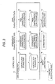
- Fig. 3 shows the schematic configuration of the data storing part 11.
- the data storing part 11 is configured to have a control data storing part 20 and a control data storage DB 21, an intermediate characteristic data storing part 22 and an intermediate characteristic data storage DB 23, and a final characteristic data storing part 24 and a final characteristic data storage DB 25.
- the control data storing part 20 acquires as control data a set value of the control value that the control instructing part 17 instructs a control target device, the measurement value actually measured by the control target device with respect to the set value, and acquired time at which the measurement value is acquired, and stores the acquired control data in the control data storage DB 21. Furthermore, the control data is acquired and stored in each of the control target devices 3 and 4. Moreover, it is fine that the set value of the control value is acquired from the control target devices 3 and 4 or from the control instructing part 17.
- the intermediate characteristic data storing part 22 acquires two intermediate characteristics A and B inspected by the intermediate characteristic measuring device 5, and associates the acquired intermediate characteristics A and B with the acquired time to store them in the intermediate characteristic data storage DB 23.
- the final characteristic data storing part 24 acquires two final characteristics A and B inspected by the final characteristic measuring device 6, associates the acquired final characteristics A and B with the acquired time, and stores them in the final characteristic data storage DB 25.
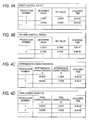
- Figs. 4A and 4B show examples of control data stored in the control data storage DB 21 with respect to the control target devices 3 and 4.
- Figs. 4C and 4D show examples of data for the intermediate characteristics stored in the intermediate characteristic data storage DB 23 and the final characteristic data storage DB 25.
- production numbers shown in Figs 4A to 4D are serial numbers for the works 2 processed by the individual devices. As described above, since the works 2 are sometimes gathered, omitted, or put back in the middle of production, even the same production numbers in the individual devices do not always correspond to the same works 2. For example, the work 2 corresponding to production number 1 of the first control target does not always correspond to production number 1 of the second control target.
- the intermediate characteristics inspected by the intermediate characteristic measuring device 5 are the characteristics of the intermediate product in the middle of production, which are inspected before inspected by the final characteristic measuring device 6. Therefore, the intermediate characteristics do not always have the same values as those of the final characteristics. Besides, two types of intermediate characteristics and final characteristics are acquired in the embodiment, but one or three types or more are acceptable.
- the scheduler 12 associates various items of data with each other stored in the data storing part 11, decides the timing to extract the associated data, and decides the timing to switch the set values of the control values to control the control target devices 3 and 4 and to switch the specification limits of the intermediate characteristics in the intermediate characteristic measuring device 5. Furthermore, the scheduler 12 sends the decided timing to the specification limit generating part 13 and the control instructing part 17.
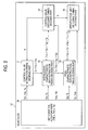
- Fig. 5 shows the schematic configuration of the scheduler 12.
- the scheduler 12 is configured to have a setting part 30, a control value extraction timing deciding part 31, an intermediate characteristic data extraction timing deciding part 32, a final characteristic data extraction timing deciding part 33, a control value switching timing deciding part 34, and a specification limit switching timing deciding part 35.
- the setting part 30 sets dead times Td1 to Td3 generated between the devices to acquire data, margin times Tm1 and Tm2, and time period Ts for the associated set, and sends them to the individual parts 31 to 35. Furthermore, it is fine that these values are acquired from a user through an input device such as a keyboard, or from a storage device, or from the other devices through a communication device.
- the first margin time Tm1 is a time period from the time to instruct switching the set values of the control values and the specification limits of the intermediate characteristics to the first acquired time of extraction from various items of data.
- the first margin time Tm1 is set so as to remove a time lag from the time to instruct switching the set value and the specification limit with respect to a device to the time to actually do the instruction with respect to the work 2, or remove a shift due to drawing a defective or to putting back a work.
- the second margin time Tm2 is a time period from the last acquired time of extraction from the intermediate characteristic data to the time to instruct switching the set value of the control value with respect to the first control target device 3.
- the second margin time Tm2 is set so as to consider processing time required to determine the set value to be switched.
- the margin times Tm1 and Tm2 and the time period Ts for a set are expressed by the number of the works 2.
- the time period Ts for a set is expressed by the number of the works 2
- the number of items of data included in each of the associated sets is constant, and thus the accuracy of statistics for each set can be nearly matched. Therefore, as in the case where any one of the devices 3 to 6 is once stopped and then again started, for example, the individual sets can be properly associated with each other even though the dead time is varied.
- a method to derive the values for the dead times Td1 to Td3 and the margin times Tm1 and Tm2 the following three methods are named. More specifically, first, a method to derive the values by calculation from the design value of the quality control system, that is, the time required for processing in each device, and the design value of the distance traveled and the rate of travel in moving works between the individual devices. Secondly, a method to derive the values by conducting test working to measure processing time and traveling time of works for actual measured values. Thirdly, a method to derive the values by conducting actual production working to measure processing time and traveling time of works for actual measured values.
- a method is named in which the initial set value before the quality control system is operated is derived from the first method and fine adjustments are done by the second or third method after operated.
- the intermediate characteristics inspected by the intermediate characteristic measuring device 5 are the characteristics of the intermediate product in the middle of production, which are inspected before inspected by the final characteristic measuring device 6. Therefore, the intermediate characteristics are not always the same values as those of the final characteristics. Moreover, two types of intermediate characteristics and final characteristics are acquired in the embodiment, but one or three types or more are acceptable.
- the scheduler 12 associates various items of data stored in the data storing part 11 with each other, decides the timing to extract the associated data, and decides the timing to switch the set values of the control values for controlling the control target devices 3 and 4 and to switch the specification limits of the intermediate characteristics in the intermediate characteristic measuring device 5. Furthermore, the scheduler 12 sends the decided timing to individual blocks 13, 14, 16 and 17.
- Fig. 5 shows the schematic configuration of the scheduler 12.
- the scheduler 12 is configured to have the setting part 30, the control value extraction timing deciding part 31, the intermediate characteristic extraction timing deciding part 32, the final characteristic extraction timing deciding part 33, the control value switching timing deciding part 34, and the specification limit switching timing deciding part 35.
- the setting part 30 sets the dead times Td1 to Td3 generated between the devices to acquire data, the margin times Tm1 and Tm2, and the time period Ts for the associated sets, and sends them to the individual parts 31 to 35. Moreover, it is fine that these values are acquired from a user through an input device such as a keyboard, or from a storage device, or from the other devices through a communication device. Besides, it is acceptable to express the margin times Tm1 and Tm2 and the time period Ts for the sets by the number of intermediate products.
- the first margin time Tm1 is a time period from the time to instruct switching the set value of the control value and the specification limit of the intermediate characteristic to the first acquired time of extraction from various items of data.
- the first margin time Tm1 is set so as to remove a time lag from the time to instruct switching the set value and the specification limit with respect to a device to the time to actually do the instruction with respect to the work 2, or remove a shift due to drawing a defective or to putting back a work.
- the second margin time Tm2 is a time period from the last acquired time of extraction from the intermediate characteristic data to the time to instruct switching the set value of the control value with respect to the first control target device 3.
- the second margin time Tm2 is set so as to consider processing time required to determine the set value to be switched.
- a method to derive the values for the dead times Td1 to Td3 and the margin times Tm1 and Tm2 the following three methods are named. More specifically, first, a method to derive the values by calculation from the design value of the quality control system, that is, the time required for processing in each device, and the design value of the distance traveled and the rate of travel in moving works between the individual devices. Secondly, a method to derive the values by conducting test working to measure processing time and traveling time of works for actual measured values. Thirdly, a method to derive the values by conducting actual production working to measure processing time and traveling time of works for actual measured values.
- a method is named in which the initial set value before the quality control system is operated is derived from the first method and fine adjustments are done by the second or third method after operated.
- the control value extraction timing deciding part 31 decides the control value extraction timing that is the timing to extract the measurement value of the control value from each item of the control data. First, it acquires the first dead time Td1, the first margin time Tm1, and the time period Ts for a set from the setting part 30, and acquires operation start time T0 that starts the operation of the scheduler 12 and switching instruction time Ti (i is an integer equal to or greater than 1) that instructs switching the set value of the control value from the control value switching timing deciding part 34. Moreover, hereinafter, the operation start time and the switching instruction time are combined to Ti (i is an integer equal to or greater than 0).
- the control value extraction timing deciding part 31 decides the time from the time Ti + Tm1 that the first margin time Tm1 is added to the operation start time or the switching instruction time Ti to the time period Ts' for a set as a first control value extraction timing. Then, it decides the time from the time Ti + Tm1 + Td1 that the first dead time Td1 is added to the start time Ti + Tm1 for the first control value extraction timing to the time period Ts for a set as a second control value extraction timing. Besides, the control value extraction timing deciding part 31 sends the start time Ti + Tm1 + Td1 for the second control value extraction timing to the intermediate characteristic extraction timing deciding part 32.
- the intermediate characteristic extraction timing deciding part 32 decides the intermediate characteristic extraction timing that is the timing to extract the intermediate characteristics from the intermediate characteristic data. First, it acquires the second dead time Td2 and the time period Ts for a set from the setting part 30, and acquires the start time Ti + Tm1 + Td1 for the second control value extraction timing from the control value extraction timing deciding part 31.
- the intermediate characteristic extraction timing deciding part 32 decides the time from the time Ti + Tm1 + Td1 + Td2 that the second dead time Td2 is added to the start time Ti + Tm1 + Td1 for the second control value extraction timing to the time period Ts for a set as the intermediate characteristic extraction timing. Furthermore, the intermediate characteristic extraction timing deciding part 32 sends the start time Ti + Tm1 + Td1 + Td2 for the intermediate characteristic extraction timing to the final characteristic extraction timing deciding part 33 as well as sends termination time Ti + Tm1 + Td1 + Td2 + Ts for the intermediate characteristic extraction timing to the control value switching timing deciding part 34.
- the final characteristic extraction timing deciding part 33 decides the final characteristic extraction timing that is the timing to extract the final characteristics from the final characteristic data. First, it acquires the third dead time Td3 and the time period Ts for a set from the setting part 30, and acquires the start time Ti + Tm1 + Td1 + Td2 for the intermediate characteristic extraction timing from the intermediate characteristic extraction timing deciding part 32.
- the final characteristic extraction timing deciding part 33 decides the time from the time Ti + Tm1 + Td1 + Td2 + Td3 that the third dead time Td3 is added to the start time Ti + Tm1 + Td1 + Td2 for the intermediate characteristic extraction timing to the time period Ts for a set as the final characteristic extraction timing. Moreover, the final characteristic extraction timing deciding part 33 sends the termination time Ti + Tm1 + Td1 + Td2 + Td3 + Ts for the final characteristic extraction timing to the specification limit switching timing deciding part 35.
- the control value switching timing deciding part 34 decides first and second control value switching timings that are the timing to switch the set values of the control values in the first and second control target devices 3 and 4. First, it acquires the first dead time Td1 and the second margin time Tm2 from the setting part 30, and acquires the termination time Ti + Tm1 + Td 1 + Td2 + Ts for the intermediate characteristic extraction timing from the intermediate characteristic extraction timing deciding part 32.
- the control value switching timing deciding part 34 decides the time Ti + Tm1 + Td1 + Td2 + Ts + Tm2 that the second margin time Tm2 is added to the termination time Ti + Tm1 + Td1 + Td2 + Ts for the intermediate characteristic extraction timing as the first control value switching timing, and decides the time Ti + Tm1 + 2 x Td1 + Td2 + Ts + Tm2 that the first dead time Td1 is added to the first control value switching timing Ti + Tm1 + Td1 + Td2 + Ts + Tm2 as the second control value switching timing.
- control value switching timing deciding part 34 sends the first control value switching timing Ti + Tm1 + Td1 + Td2 + Ts + Tm2 as the switching instruction time Ti next time to the control value extraction timing deciding part 31 and the specification limit switching timing deciding part 35.
- the specification limit switching timing deciding part 35 decides the specification limit switching timing that is the timing to switch the specification limit of the intermediate characteristic in the intermediate characteristic measuring device 5. First, it acquires the first and second dead times Td1 andTd2 from the setting part 30, and acquires the termination time Ti + Tm1 + Td1 + Td2 + Td3 + Ts for the final characteristic extraction timing from the final characteristic extraction timing deciding part 33, and acquires the switching instruction time Ti from the control value switching timing deciding part 34.
- the specification limit switching timing deciding part 35 specifies the switching instruction time Ti that appears first after the termination time Ti + Tm1 + Td1 + Td2 + Td3 + Ts for the final characteristic extraction timing, and decides the time Ti + Td1 + Td2 that the specified switching instruction time Ti is added to the first and second dead times Td1 and Td2 as the specification limit switching timing.
- Fig. 6 shows the exemplary timing operation of the scheduler 12 of the configuration.
- areas denoted by n to (n + 3 ) are sets associated between the individual devices 3 to 6.
- the first dead time Td1 is two seconds
- the second dead time Td2 is four seconds
- the third dead time Td3 is 20 seconds.
- the first and second margin times Tm1 and Tm2 are 0.75 second
- the time period Ts for a set is 4.5 seconds
- the control data can be extracted by the intermediate characteristic extraction timing, and the intermediate characteristic data can be extracted at the intermediate characteristic extraction timing.
- the set values of the control values for the control target devices 3 and 4 are determined based on the extracted control data and the intermediate characteristic data, and control instructions to switch to the determined set values are sent to the control target devices 3 and 4.
- Tn + 1 the switching instruction item
- the intermediate characteristic data can be extracted by the final characteristic extraction timing, and the final characteristic data can be extracted at the final characteristic extraction timing. Therefore, as described above, the specification limits of the intermediate characteristics are determined based on the extracted intermediate characteristic data and final characteristic data, and a control instruction to switch to the determined specification limits are sent to the intermediate characteristic measuring device 5.
- the extraction of the intermediate characteristic data and the final characteristic data and the switching of the specification limits are repeated.
- Fig. 14 shows the types of the improper acquired data generated in general production sites, and the cause and contents. As shown in the drawing, as the types of the improper acquired data, 'outlier', 'remeasurement', 'putting back', and 'removed product' are named.
- the 'outlier' shows the case where the measurement value is greatly deviated from the normal value.
- the data distribution is formed nearly in the normal distribution that data gathers close to the mean value. Therefore, when the outlier is included ina set as the acquired data, it is difficult to properly estimate the data distribution of the set because the outlier greatly influences it.
- the 'remeasurement' shows the case where a device fails to measure, for example, and thus again measures the same work 2.
- multiple measurement values exist for the same work 2, and the measurement value before remeasurement is highly likely to be abnormal. Therefore, when the measurement value before remeasurement is included as the acquired data in a set, it is difficult to properly estimate the data distribution of the set as similar to the case of the outlier.
- the 'putting back' shows the case where the work 2 determined as out-of-specification by the intermediate characteristic measuring device 5, for example, is put back to the process steps done by the second control target device 4.
- the work 2 determined as out-of-specification by the intermediate characteristic measuring device 5, for example, is put back to the process steps done by the second control target device 4.
- the 'removed product' shows the case where the work 2 determined as out-of-specification by the intermediate characteristic measuring device 5, for example, is removed right after its inspection.
- the work 2 to be removed there are the acquired data of the intermediate characteristic measuring device 5 and the acquired data of the first and second control target devices 3 and 4 in the previous process steps of the intermediate characteristic measuring device 5.
- the acquired data of the final characteristic measuring device 6 there is not the acquired data of the final characteristic measuring device 6 in the subsequent process steps of the intermediate characteristic measuring device 5. Therefore, relating to the sets associated between devices 3 to 6, the works 2 corresponding to the acquired data included in each set are varied between the sets relating to the first and second control target devices 3 and 4 and the intermediate characteristic measuring device 5, and the set relating to the final characteristic measuring device 6.
- the improper acquired data is removed out of the set.
- whether to remove the acquired data depends on which types the improper acquired data is and which of the previous process steps or the subsequent process steps the set is included.
- the individual devices 3 to 6 add improper type information that indicates the types of improper data to the acquired data, and sends it to the quality control apparatus 10 to store it in the data storing part 11. Furthermore, the quality control apparatus 10 stores a table shown in Fig. 15 in a storing part, not shown. This table stores the types of the improper acquired data, and information that indicates whether the acquired data is invalid data to be removed or valid data to be left when the sets for the previous process steeps or the subsequent process steps are associated.
- the scheduler refers to the table shown in Fig. 15 and improper type information stored in the data storing part 11, and removes invalid data out of the acquired data to associate the sets of the acquired data. Therefore, since the improper acquired data can be removed in accordance with the types and which of the previous process steps or the subsequent process steps the data is associated, the statistical processes can be conducted accurately. In addition, when the acquired data does not fall in the improper data, it is processed as valid data. Besides, when the acquired data falls in multiple types of improper data, it is processed as invalid data when it is at least one type fallen in invalid data.
- the specification limit generating part 13 extracts a set of the intermediate characteristic data from the intermediate characteristic data storage DB 23 based on the intermediate characteristic extraction timing decided by the scheduler 12, extracts a set of the final characteristic data from the final characteristic data storage DB 25 based on the final characteristic extraction timing decided by the scheduler 12, and generates the specification limits of the intermediate characteristics based on the extracted set. Furthermore, the specification limit generating part 13 sends the generated specification limits to the intermediate characteristic measuring device 5 based on the specification limit switching timing decided by the scheduler 12.
- Figs. 7A and 7B show the operation of generating the specification limits.
- the mean value X - and the standard deviation ⁇ relating to the distribution of the extracted final characteristic A are determined.
- the mean value Xa - and the standard deviation ⁇ a relating to the distribution of the extracted intermediate characteristic A are determined.
- the operation of generating the specification limits are repeated with respect to the intermediate characteristics such as the intermediate characteristic B other than the intermediate characteristic A, and thus the specification limit for each is generated. Moreover, when the specification limit is only the upper limit or the lower limit, the specification limit can be generated similarly.
- the specification limits of the intermediate characteristics are stricter than the specification limits of the final characteristics. More specifically, the specification limit generating part 13 desirably adjusts the specification limits generated in accordance with the equations based on the safety factor.
- the safety factor is three to four experimentally, but it is calculated based on the tolerance design proposed in quality engineering in recent years (for example, see the second and third chapters inNon-patent Document 1).
- the tolerance design is a method in which quality is converted by the loss function to calculate the optimum tolerance that minimizes the loss.
- ⁇ is the safety factor
- A is the discard cost when a defective is removed in the intermediate inspection
- A0 is the discard cost when a defective is removed in the final inspection.
- the above equation is held because the intermediate characteristic is a desired target characteristic as it is closer to the target value as much as possible.
- the specification limit of the intermediate characteristic is only the upper specification limit Sua between the equations above.
- the impact creating part 14 creates an impact that indicates how the intermediate characteristics are varied when the control values are switched based on a request from the estimating part 16, sends the created impact to the estimating part 16, and stores it in the impact storage DB 15.
- the impact creating part 14 sets the initial value for an impact beforehand before the scheduler 12 is operated, and stores it in the impact storage DB 15.
- the initial value for an impact can be determined by calculating a change in the mean value of the controllable factor (control value) and a variation in the mean value and in variations (variance and standard deviation) of the intermediate characteristics with respect to the controllable factor.
- Fig. 8 shows the process operation of the impact creating part 14 after the scheduler 12 is operated.
- two sets of the control data relating to the first control target device 3 (control target 1) are extracted from the control data storage DB 21 (hereinafter, it is called 'first control data').
- two sets of the control data relating to the second control target device 4 (control target 2) are extracted from the control data storage DB 21 (hereinafter, it is called 'second control data').
- two sets of the intermediate characteristic are extracted from the intermediate characteristic data storage DB 23 (S30).
- the mean value of the set of the intermediate characteristic extracted at this time is calculated (S31), and it is determined whether the difference between the calculated mean value and the estimated value of the mean value of the intermediate characteristic acquired from the estimating part 16 is greater than a predetermined value D (S32). When it is greater (YES at S32), the following process operation is conducted, whereas it is not greater (NO at S32), the process operation of the impact creating part 14 is ended.
- a change this time with respect to a change at the previous time is calculated with respect to the mean value of the control data (S33). More specifically, the mean value relating to the set of the first control data (measurement value) extracted based on the first control value extraction timing at the previous time is X(n - 1), and the mean value relating to the set of the first control data (measurement value) extracted based on the first control value extraction timing this time is X(n). Then, a change this time relating to the mean value of the first control data with respect to that at the previous time is expressed by the following equation.
- a c ⁇ h ⁇ a ⁇ n ⁇ g ⁇ e i ⁇ n t ⁇ h ⁇ e m ⁇ e ⁇ a ⁇ n v ⁇ a ⁇ l ⁇ u ⁇ e o ⁇ f t ⁇ h ⁇ e f ⁇ i ⁇ r ⁇ s ⁇ t c ⁇ o ⁇ n ⁇ t ⁇ r ⁇ o ⁇ l d ⁇ a ⁇ t ⁇ a X n - X ⁇ n - 1 .
- a variation this time with respect to that at the previous time is calculated relating to the mean value and variance of the intermediate characteristic (S34). More specifically, the mean value and variance relating to the set of the intermediate characteristic A extracted based on the intermediate characteristic extraction timing at the previous time are Y(n - 1) and Z (n - 1), respectively, and the mean value and variance relating to the set of the intermediate characteristic A extracted based on the intermediate characteristic extraction timing this time are Y(n) and Z(n), respectively.
- the procedures are used to also determine an impact caused by the second control data and an impact on the other intermediate characteristic B. More specifically, in practice, the following is to be created: impacts on the mean value and variance of the intermediate characteristic A by the first control data, impacts on the mean value and variance of the intermediate characteristic A by the second control data, impacts on the mean value and variance of the intermediate characteristic B by the first control data, and impacts on the mean value and variance of the intermediate characteristic B by the second control data.
- the created impacts are sent to the estimating part 16, the impacts stored in the impact storage DB 15 are updated (S36), and the operation of the impact creating part 14 is ended.
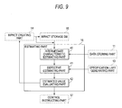
- Fig. 9 shows the schematic configuration of the estimating part 16.
- the estimating part 16 is configured to have an intermediate characteristic estimating part (intermediate characteristic estimating module) 40, a defective estimating part (defective number estimating module) 41, and an estimated value evaluating part (variation deciding module) 42.
- the intermediate characteristic estimating part 40 uses the impact read out of the impact storage DB 15 to estimate a variation in the mean value or the standard deviation (variance) of the intermediate characteristic when the set value of the control value is switched.
- the defective estimating part 41 estimates the number of defectives when the distribution of the intermediate characteristic is varied by the variation estimated by the intermediate characteristic estimating part 40, and evaluates by the sum of the number of individual defectives.
- the estimated value evaluating part 42 determines a variation in the set value of the control value when the number of defectives is the minimum, and sends it to the control instructing part 17.
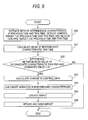
- Fig. 10 shows the process operation of the estimating part 16 of the configuration.
- the intermediate characteristic estimating part 40 extracts a set of the intermediate characteristic data from the intermediate characteristic data storage DB 23 of the data storing part 11 based on the intermediate characteristic extraction timing decided by the scheduler 12 (S40).
- the intermediate characteristic estimating part 40 creates a switching pattern that is a combination of the switching amount of the set values of the control values relating to the individual control target devices 3 and 4 (S41).
- Fig. 11 shows an example of the switching pattern in a table form.
- the switching pattern is expressed by a two-dimensional table as shown in Fig. 11 .
- the number of the switching amounts for the set values of the control values can be experimentally decided from the switching margin possibly effective and the tolerance of the switching margin, but it can be decided by any manners.
- the number of the switching amounts is five in the control target 1 (control target device 3) and the control target 2 (control target device 4). Furthermore, the switching margin for the control target 1 is 0.003, and the switching margin for the control target 2 is 0.005. Moreover, as shown in Fig. 11 , 0.000, that is, 'not switching' is included in the switching amount in the embodiment, but it is not necessarily included.
- the mean value of the intermediate characteristic or the estimated value of the standard deviation when the set values of the control values are switched is determined with respect to each of the switching patterns, and thus the estimated value table shown in Fig. 11 is completed. More specifically, the current impact is acquired from the impact storage DB 15 (S42), and the acquired impact is multiplied by the switching margin (switching amount) for the set value of the control value. Therefore, the mean value or the variation in the variance of the intermediate characteristic is determined when the set value of the control value is switched.
- the variation is added to the mean value or variance of the extracted current intermediate characteristic.
- the variance the square root is taken after this and converted to standard deviation.
- the estimated value of the mean value or the standard deviation of the intermediate characteristic is determined for each combination of the switching amount for the set values of the control values for the control target, and the estimated value table shown in Fig. 11 is competed (S43).
- Fig. 11 shows the estimated value Xa, i, j for the mean value.
- the switching margin for the set value of the control value is a
- the mean value of the intermediate characteristic A is X -
- the standard deviation of the intermediate characteristic A is ⁇
- an impact for the mean value of the intermediate characteristic A is k1
- an impact for the variance of the intermediate characteristic A is k2.
- the defective estimating part 41 uses the estimated value determined by the intermediate characteristic estimating part 40 to create the distribution of the intermediate characteristic after switched for every switching pattern, and estimates the number of defectives for the intermediate characteristic. More specifically, the specification criteria (specification limits) are moved by the change in the created distribution of the intermediate characteristic (S44), and it is determined whether elements (individual intermediate characteristics) included in the extracted set are passed or failed (S45):
- the estimated value evaluating part 42 sums the number of defectives for the individual intermediate characteristics determined by the defective estimating part 41 (S46), and selects the switching pattern that the summed number of defectives is the minimum (S47).
- S46 the number of defectives for the individual intermediate characteristics determined by the defective estimating part 41
- S47 the switching pattern that the summed number of defectives is the minimum
- the NG flag is indicated as bit data as 1 (ON) when it is given, whereas 0 (OFF) when it is not given.
- the logical OR (OR) is taken with respect to the NG flags of the intermediate characteristics A to C for every production number, and the flags are counted to determine the sum of the number of defectives.
- the estimated value evaluating part 42 calculates the total sum of the number of defectives (the total number of defectives) for every switching pattern, and thus a total defective number table corresponding to the estimated value table is created.
- Fig. 13 shows an example of the total defective number table, which corresponds to the estimated value table shown in Fig. 11 .
- the estimated value evaluating part 42 refers to the total defective number table to select the switching pattern that the total number of defectives is the minimum. In the case of Fig.
- a combination that the switching amount for the set value of the control value of the control target 1 (control target device 3) being 0.003 with the switching amount for the set value of the control value of the control target 2 (control target device 4) being 0.010 is the minimum by the total number of defectives being 15, and thus this switching pattern is selected.
- the estimated value evaluating part 42 sends the selected switching pattern (the combination of the switching amounts) to the control instructing part 17 (S48). Furthermore, it sends the estimated value of the intermediate characteristic corresponding to the selected switching pattern to the impact creating part 14. After that, the operation of the estimating part 16 is ended.
- the switching pattern that the total number of defectives is the minimum is selected; and consequently it can be considered that the switching amount for one of control targets 1 and 2 or for both is 0.000, that is, switching is unnecessary. In this case, sending the switching amount for this control target can be omitted to the control instructing part 17.
- the control instructing part 17 acquires the combination for every control target relating to the switching pattern selected by the estimated value evaluating part 42, that is, the switching amounts for the set values of the control values, switches the set value of the control value of each of the control target devices 3 and 4 based on the acquired switching pattern, and sends the switched set values as control instructions to the control target devices 3 and 4.
- the scheduler 12 desirably adjusts these time lags as well to decide the association of data and timing.
- the data storing part 11 stores the acquired time in the embodiment, but it is fine that it receives the measured time that is the time measured by the individual devices 3 to 6 from each device for storing.
- the scheduler 12 is to use the measured time for association.
- control target devices 3 and 4 are used in the embodiment, but a single control target device can be used, and the control target device and the intermediate characteristic measuring device can be further increased.
- each block of the quality control apparatus 10 is configured of hardware logic and is implemented by software with a CPU as below.
- the quality control apparatus 10 has a CPU which executes instructions of a control program for implementing each function, a ROM which stores the program, a RAM which runs the program, and a storage device (recording medium) such as memory which stores the program and various items of data.
- the object of the invention can also be achieved in which a recording medium that the program codes of the control program of the quality control apparatus 10 (an execute form program, an intermediate code program, and a source program), which is software for implementing the functions, are readable by a computer is supplied to the quality control apparatus 10 and the computer (or the CPU or MPU) reads the program codes recorded in the recording medium for execution.
- tapes such as magnetic tape and cassette tape
- disks including magnetic disks such as a flexible disk and a hard drive
- optical disks such as CD-ROM, MO, MD, DVD and CD-R
- cards such as an IC card (including a memory card) and an optical card
- semiconductor memory such as mask ROM, EPROM, EEPROM and flash ROM.
- the quality control apparatus 10 is configured to be connectable to a communication network and the program codes are supplied through the communication network.
- the communication network is not defined particularly.
- the following can be used: the Internet, an intranet, an extranet, LAN, ISDN, VAN, a CATV communications network, a virtual private network, a telephone network, a mobile communications network, and a satellite communications network.
- transmission media to configure the communication networks are not limited particularly.
- cables such as IEEE 1394, USB, electric power line transmission, cable TV lines, telephone lines, and ADSL lines, or radio such as infrared rays including IrDA or remote control, Bluetooth (trade mark), 802.11 radio, HDR, mobile telephone networks, satellite connections, and terrestrial digital networks.
- radio such as infrared rays including IrDA or remote control, Bluetooth (trade mark), 802.11 radio, HDR, mobile telephone networks, satellite connections, and terrestrial digital networks.
- the invention can be implemented in the forms of carrier waves that implement the programcodes to be electronically transmitted, or of data signal rows.
- the quality control apparatus according to the invention can be applied to devices that control various processes to maintain proper conditions such as control over household electrical products, in addition to manufacturing processes.
Landscapes
- Engineering & Computer Science (AREA)
- Business, Economics & Management (AREA)
- General Physics & Mathematics (AREA)
- Quality & Reliability (AREA)
- Physics & Mathematics (AREA)
- Entrepreneurship & Innovation (AREA)
- Economics (AREA)
- Human Resources & Organizations (AREA)
- Strategic Management (AREA)
- Marketing (AREA)
- Operations Research (AREA)
- Game Theory and Decision Science (AREA)
- Tourism & Hospitality (AREA)
- Educational Administration (AREA)
- General Business, Economics & Management (AREA)
- Development Economics (AREA)
- Theoretical Computer Science (AREA)
- Automation & Control Theory (AREA)
- General Factory Administration (AREA)
- Management, Administration, Business Operations System, And Electronic Commerce (AREA)
Abstract
Description
- The present invention relates to a quality control apparatus for controlling a manufacturing process and a control method of the same, a quality control program, and a recording medium recorded with the program for manufacturing products of predetermined quality.
- Traditionally, an effort to improve the quality of products is taken, and various quality control methods are proposed.
- For example, in order to realize traceability, a management method is proposed in which identification codes such as bar codes are assigned to intermediate products for products and to bases on which the intermediate product is placed. Furthermore, in order to realize traceability, an identification method is proposed in which intermediate products are identified in order of the intermediate products to be put in each of manufacturing process steps.
- Moreover, a method is proposed in which the cause-and-effect relationship between controllable factors and product characteristics is fully comprehended to specify the controllable factors for obtaining optimum product characteristics. Besides, a method is proposed in which the entire conditions of controllable factors are fixed to maintain product characteristics (for example, see
Patent Documents 2 and 3) . - In addition, a method is proposed in which indicators for individual product characteristics are provided to do comprehensive evaluation from these indicators. Furthermore, a method is proposed in which it is determined whether product characteristics is passed or failed at the final process step in production and controlled parameters are adjusted in manufacturing process steps when a product is determined as a defective (for example, see Patent Document 1).
- Patent Document 1:
JP-A-7-141005 (published on June, 2, 1995 - Patent Document 2:
JP-A-6-110504 (published on April, 22, 1994 - Patent Document 3:
JP-A-4-188301 (published on July, 6, 1992 - Non-patent Document 1: TAGUCHI Gen'ichi, and YOSHIZAWAMasataka, Hinshitsu Kogaku Koza 1/Kaihatsu-Sekkie Dankai no Hinshitsu Kogaku, Nihon Kikaku Kyokai, 1988
- However, in the method that assigns the identification code for management, there is a problem that production costs are increased. Furthermore, defectives are often drawn, reworked, and put back in manufacturing process steps. On this account, the method that identifies the intermediate products in order of the intermediate products does not always identify the intermediate products correctly.
- Moreover, since many controllable factors exist, many verification experiments are required to fully comprehend the cause-and-effectrelationship between the controllable factors and the product characteristics. Besides,the more complicated the cause-and-effect relationship is, the more difficult the full comprehension is. Furthermore, even though all the conditions of the controllable factors are fixed, an unobservable change in factors over time can varies the product characteristics.
- Moreover, in the method that performs comprehensive evaluation from the indicators for the individual product characteristics, since the product characteristics often have a trade-off relationship each other, it is difficult to perform comprehensive evaluation. Besides, in the method that determines whether the product characteristics are passed or failed at the final process step in production, defectives are continuously fabricated until the final process step, and thus unnecessary production time and materials are increased. Furthermore, the intervals between control feedback loops are also increased.
- The invention has been made in view of the problems. An obj ect is to provide a quality control apparatus which associates various items of data with each other that are collected at different process steps in production sites where traceability is difficult to do.
- In order to solve the problem, a quality control apparatus according to the invention is a quality control apparatus which controls a manufacturing process in order to manufacture products of predetermined quality, the apparatus including:
- a storing module which collects measurement data measured by multiple measuring devices disposed in a manufacturing process and stores the collected measurement data along with measured time or collected time; and
- an associating module which associates the measurement data of the measuring devices with each other in consideration of dead time generated between the measuring devices at measured time or collected time.
- An intermediate product measured by a certain device is to be measured by the subsequent device at the time after dead time has roughly elapsed from when the intermediate product was measured. Therefore, the time measured by each of the measuring devices or the time collected by each of the measuring devices can be roughly associated by the dead time.
- Thus, according to the configuration, since the collected measurement data is associated with the measured time or collected time, the associating module roughly associates the measured time or collected time by the dead time generated between the measuring devices, and therefore the measurement data of the measuring devices can be associated with each other.
- Furthermore, the dead time is used only by the associating module, and does not influence the data stored in the storing module even though the dead time is changed. Therefore, the dead time can be changed easily.
- Moreover, it is acceptable that the associating module associates given numbers of items of measurement data of the multiple measuring devices with each other. In this case, a set formed of the given number of items of measurement data is formed in each of the measuring devices, and the sets in the multiple measuring devices are associated with each other. Therefore, since the number of items of measurement data included in the individual associated sets is constant, the accuracy of statistics of each set can be nearly matched. Besides, the set is formed based on the number of measurements, not on a time period measured by the measuring device, and thus the individual sets can be properly associated with each other even though a certain process step in a manufacturing process is stopped for a long time and then started, for example.
- In addition, desirably, when improper measurement data is included in the measurement data to be associated with each other, the associating module stops association of the improper measurement data with the measurement data that is the measurement data measured by the other measuring device and corresponds to the improper measurement data.
- Here, for the improper measurement data, the following is named: the case where the measurement value is an outlier that is greatly deviated from a normal value, the case where a device remesures the same intermediate product because of failed measurement, the case where the intermediate product determined as out-of-specification in intermediate inspection is put back to the process step on the upstream side, and the case where the intermediate product determined as out-of-specification in intermediate inspection is removed right after its inspection.
- The improper measurement data causes the reduced accuracy in conducting statistical processes. Thus, according to the configuration, since the improper measurement data is not used for the association, the accuracy of the statistical processes can be prevented from being reduced.
- Furthermore, when the intermediate product is put back, relating to the intermediate product put back, there is the measurement data of the measuring device at the process step where the intermediate product is put back and on the downstream side thereof, but there is no measurement data of the measuring device on the upstream side of the process step where the intermediate product is put back. Therefore, desirably, when an intermediate product is put back at a certain process step in a manufacturing process, the associating module stops association of measurement data relating to the intermediate product of the measuring device on an upstream side of the process step with measurement data relating to the intermediate product of the measuring device at the process step and on a downstream side thereof.
- Moreover, when the intermediate product is removed right after its inspection, relating to the intermediate product to be removed, there is the measurement data of the measuring device at the process step where the intermediate product is removed and on the upstream side thereof, but there is no measurement data of the measuring device on the downstream side of the process step where the intermediate product is removed. Thus, desirably, when an intermediate product is removed at a certain process step in a manufacturing process, the associating module stops association of measurement data of the measuring device on a downstream side of the process step with measurement data relating to the intermediate product of the measuring device at the process step and on an upstream side thereof.
- A quality control apparatus according to the invention is a quality control apparatus which controls a manufacturing process in order to manufacture products of predetermined quality, the apparatus including:
- a storing module which collects and stores intermediate characteristic data of an intermediate product measured by an intermediate characteristic measuring device and final characteristic data of a completed product measured by a final characteristic measuring device;
- a specification limit generating module which generates an intermediate characteristic specification limit set to the intermediate characteristic measuring device based on a data distribution of the final characteristic data stored in the storing module and a final characteristic specification limit set to the final characteristic measuring device; and
- a specification limit setting control module which controls the intermediate characteristic measuring device so as to set the generated specification limit generated by the specification limit generating module.
- Here, the intermediate characteristic measuring device inspects the intermediate characteristics of the intermediate product in the middle of production, and determines whether the intermediate product is passed or failed based on the intermediate characteristic specification limit. Since the defective is removed in the middle of production by using the intermediate characteristic measuring device, unnecessary production time for the defective can be eliminated and the intervals between control feedback loops can be reduced.
- Then, according to the configuration, since the specification limit generating module switches the intermediate characteristic specification limit based on the final characteristic of the completed product, the intermediate characteristic specification limit can be automatically adjusted even though various parameters in the manufacturing process are varied.
- Furthermore, desirably, the specification limit generating module generates the intermediate characteristic specification limit based on a differential between a mean value of the data distribution of the final characteristic data and the final characteristic specification limit. Moreover, desirably, the specification limit generating module generates the intermediate characteristic specification limit so that a ratio of a differential between a mean value of a data distribution of the intermediate characteristic data stored in the storing module and the intermediate characteristic specification limit with respect to the differential between the mean value of the data distribution of the final characteristic data and the final characteristic specification limit is a ratio of a variation value of the data distribution of the intermediate characteristic data with respect to a variation value of the data distribution of the final characteristic data.
- Here, the variation value of the data distribution indicates the degree of variations in the data distribution. For example, standard deviation, variance, and half width are named.
- Besides, desirably, the specification limit generating module further generates the intermediate characteristic specification limit based on a safety factor. In this case, the intermediate product can be efficiently removed based on the intermediate characteristic specification limit. In addition, the safety factor can be also set based on empirical rules, but desirably, it is calculated based on discard cost when the completed product is removed based on the final characteristic specification limit and discard cost when the intermediate product is removed based on the intermediate characteristic specification limit.
- Furthermore, desirably, the storing module stores the intermediate characteristic data and the final characteristic data along with measured time or collected time, the quality control apparatus further includes:
- an associating module which associates the intermediate characteristic data with the final characteristic data in consideration of dead time generated between the intermediate characteristic measuring device and the final characteristic measuring device at measured time or collected time. In this case, since the collected intermediate characteristic data and the final characteristic data are associated with measured time or collected time, the associating module roughly associates the measured time or collected time by the dead time generated between the intermediate characteristic measuring device and the final characteristic measuring device. Thus, the intermediate characteristic data is associated with the final characteristic data.
- Moreover, desirably, the specification limit generating module generates a subsequent specification limit by using the intermediate characteristic data and the final characteristic data collected by the storing module after a given time period has elapsed from when the specification limit setting control module controlled the intermediate characteristic measuring device. Generally, when the set value of the device is switched, a slight time lag is generated until switching is completed. Therefore, in the case above, since data in the middle of switching is not used, more accurate control is possible.
- A quality control apparatus according to the invention is a quality control apparatus which controls a control target device disposed in a manufacturing process in order to manufacture products of predetermined quality, the apparatus including:
- a storing module which collects and stores a set value of a control value set as a target value to the control target device, control data that is a measurement value of the control value measured by the control target device with respect to the set value of the control value, and intermediate characteristic data of an intermediate product measured by an intermediate characteristic measuring device;
- an intermediate characteristic estimating module which estimates a variation in a data distribution of the intermediate characteristic data when the set value of the control value stored in the storing module is switched;
- a defective number estimating module which estimates a number of defectives based on a variation in the data distribution of the intermediate characteristic data estimated by the intermediate characteristic estimating module and an intermediate characteristic specification limit;
- a switching amount deciding module which decides a switching amount for the set value of the control value so that the number of defectives estimated by the defective number estimating module is the minimum; and
- a control switching module which switches the set value of the control value of the control target device based on the switching amount decided by the switching amount deciding module.
- Here, for the amount indicating the data distribution, various amounts can be used such as the mean value and the variation value.
- According to the configuration, a variation in the data distribution of the intermediate characteristic data is estimated when the set value of the control value is switched, and the number of defectives to be generated is estimated. Then, the switching amount for the set value of the control value is decided so that the estimated number of defectives is the minimum, and the set value of the control value of the control target device is switched.
- Therefore, since control over the control target device is switched so that the intermediate product is inspected in the middle of production to decrease the number of the defectives in the intermediate products, the intervals between control feedback loops can be reduced. Furthermore, since a variation in the data distribution is estimated to consider variations in data, the number of defectives to be generated can be more accurately estimated.
- Moreover, desirably, the quality control apparatus further includes an impact storingmodule which stores an impact that indicates a degree of a variation in the data distribution of the intermediate characteristic data with respect to a change in a mean value of the control data,
wherein the intermediate characteristic estimating module estimates the variation in the data distribution of the intermediate characteristic data based on the switching amount for the set value of the control value stored in the storing module and the impact stored in the impact storing module, and
the switching amount deciding module decides a switching amount for the set value of the control value so that the number of defectives estimated by the defective number estimating module is the minimum. In this case, the correlation between a change in the mean value of the control data and a variation in the data distribution of the intermediate characteristic data is determined. Thus, the variation in the data distribution of the intermediate characteristic data can be more accurately estimated, and the number of defectives to be generated can be more accurately estimated. - Furthermore, desirably, the quality control apparatus further includes an impact creating module which creates the impact and stores it in the impact storing module when a difference more than a given amount is generated between the data distribution of the intermediate characteristic data corresponding to a switching amount for the set value of the control value decided by the switching amount deciding module and the distribution of the intermediate characteristic data collected by the storing module after the control switching module switches control. In this case, the impact can be automatically adjusted even though the variation is generated in the manufacturing process. Thus, a variation in the data distribution of the intermediate characteristic data can be more accurately estimated, and products of proper quality can be manufactured.
- Moreover, desirably, the storing module further collects and stores final characteristic data of a completed product measured by a final characteristic measuring device, the quality control apparatus further includes:
- a specification limit generating module which generates an intermediate characteristic specification limit set to the intermediate characteristic measuring device based on a data distribution of the final characteristic data stored in the storing module and a final characteristic specification limit set to the final characteristic measuring device, and
- the defective number estimating module uses the intermediate characteristic specification limit generated by the specification limit generating module. In this case, since the intermediate characteristic specification limit can be automatically corrected even though the variation is somewhat generated in the manufacturing process, the number of defectives to be generated can be more accurately estimated, and products of proper quality can be manufactured.
- Besides, desirably, the storing module stores the control data and the intermediate characteristic data along with measured time or collected time, the quality control apparatus further includes:
- an associating module which associates the control data with the intermediate characteristic data in consideration of dead time generated between the control target device and the intermediate characteristic measuring device at measured time or collected time. In this case, since the collected control data and the intermediate characteristic data are associated with the measured time or collected time, the associating module roughly associates the measured time or collected time by the dead time generated between the control target device and the intermediate characteristic measuring device, and thus the control data can be associated with the intermediate characteristic data.
- In addition, desirably, the intermediate characteristic estimating module estimates a subsequent data distribution of the intermediate characteristic data by using the intermediate characteristic data collected by the storing module after a given time period has elapsed from when the control switching module switched control. In this case, since data in the middle of switching the control is not used, further accurate control is possible.
- A control method of a quality control apparatus according to the invention is a control method of a quality control apparatus which controls a manufacturing process in order to manufacture products of predetermined quality,
the apparatus including: - a storing module which collects measurement data measured by the multiple measuring devices disposed in a manufacturing process and stores the collected measurement data along with measured time or collected time, and
- an association step of associating the measurement data of the measuring devices with each other in consideration of dead time generated between the measuring devices at measured time or collected time.
- According to the method, since the collected measurement data is associated with the measured time or collected time, the associating module roughly associates the measured time or collected time by the dead time generated between the measuring devices, and thus the measurement data of the measuring devices can be associated with each other. Furthermore, the dead time is used only at the association step, and the data stored in the storing module is not influenced even though dead time is changed. Therefore, the dead time can be changed easi ly.
- A control method of a quality control apparatus according to the invention is a control method of a quality control apparatus which controls a manufacturing process in order to manufacture products of predetermined quality,
the apparatus including: - a storing module which collects and stores intermediate characteristic data of an intermediate product measured by an intermediate characteristic measuring device and final characteristic data of a completed product measured by a final characteristic measuring device, and
- a specification limit generating step of generating an intermediate characteristic specification limit set to the intermediate characteristic measuring device based on a data distribution of the final characteristic data stored in the storing module and a final characteristic specification limit set in the final characteristic measuring device; and
- a specification limit setting control step of controlling the intermediate characteristic measuring device so as to set the specification limit generated at the specification limit generating step.
- According to the method, since the intermediate characteristic specification limit is switched based on the final characteristic of the completed product at the specification limit generating step, the intermediate characteristic specification limit can be automatically adjusted even though various parameters are changed in the manufacturing process.
- A control method of a quality control apparatus according to the invention is a control method of a quality control apparatus which controls a control target device disposed in a manufacturing process in order to manufacture products of predetermined quality,
the apparatus including: - a storing module which collects and stores a set value of a control value set as a target value to the control target device, control data that is a measurement value of a control value measured by the control target device with respect to the set value of the control value, and intermediate characteristic data of an intermediate product measured by an intermediate characteristic measuring device, and
- an intermediate characteristic estimating step of estimating a variation in a data distribution of the intermediate characteristic data when the set value of the control value stored in the storing module is switched;
- a defective number estimating step of estimating a number of defectives based on the variation in the data distribution of the intermediate characteristic data estimated at the intermediate characteristic estimating step and an intermediate characteristic specification limit;
- a switching amount deciding step of deciding a switching amount for the set value of the control value so that the number of defectives estimated at the defective number estimating step is the minimum; and
- a control switching step of switching the set value of the control value of the control target device based on the switching amount decided at the switching amount deciding step.
- According to the method, the variation in the data distribution of the intermediate characteristic data is estimated when the set value of the control value is switched, and the number of defectives to be generated is estimated. Then, a switching amount for the set value of the control value is decided so that the estimated number of defectives is the minimum, and the set value of the control value of the control target device is switched. Therefore, since control over the control target device is switched so that the intermediate product is inspected in the middle of production to decrease the number of the defectives in the intermediate products, the intervals between control feedback loops can be reduced. Moreover, since the variation in the data distribution is estimated to also consider variations in data, the number of defectives to be generated can be more accurately estimated.
- Besides, the individual modules in the quality control apparatus can be run on a computer by a quality control program. In addition, the quality control program is stored in a computer readable recording medium, and thus the quality control program can be executed on a given computer.
- As described above, the quality control apparatus according to the invention exerts an advantage that since the collected measurement data is associated with the measured time or collected time, the associating module roughly associates the measured time or collected time by the dead time generated between the measuring devices and thus the measurement data of the measuring devices can be associated with each other.
- The teachings of the invention can be readily understood by considering the following detailed description in conjunction with the accompanying drawings, in which:
-
Fig. 1 is a block diagram illustrating the schematic configuration of a quality control system including a quality control apparatus of an embodiment according to the invention; -
Fig. 2 is a flow chart illustrating the process operation of the quality control apparatus; -
Fig. 3 is a functional block diagram illustrating the schematic configuration of a data storing part in the quality control apparatus; -
Figs. 4A to 4D are diagrams illustrating examples of data stored in the data storing part in a table form, and show examples of first control data, second control data, intermediate characteristic data, and final characteristic data; -
Fig. 5 is a functional block diagram illustrating the schematic configuration of a scheduler in the quality control apparatus; -
Fig. 6 is a timing chart illustrating the exemplary timing operation of the scheduler; -
Fig. 7A is a graph illustrating the data distribution of the final characteristic data, andFig. 7B is a graph illustrating the data distribution of the intermediate characteristic data, showing that specification limits are switched based on the data distribution of the final characteristic data; -
Fig. 8 is a flow chart illustrating the process operation of an impact creating part in the quality control apparatus; -
Fig. 9 is a functional block diagram illustrating the schematic configuration of an estimating part in the quality control apparatus; -
Fig. 10 is a flow chart illustrating the process operation of the estimating part; -
Fig. 11 is a diagram illustrating an example of an estimated value table for intermediate characteristics created by an intermediate characteristic estimating part of the estimating part in a table form; -
Fig. 12 is a diagram illustrating an example of a passed/failed list for intermediate characteristics created by a defective estimating part in the estimating part in a table form; -
Fig. 13 is a diagram illustrating an example of a total defective number table created by an estimated value evaluating part in the estimating part in a table form; -
Fig. 14 is a diagram illustrating types of improper acquired data generated in general production sites, and the correlation between the exemplary cause and the description in a table form; and -
Fig. 15 is a diagram illustrating types of improper acquired data, and the correlation between information and reasons showing whether acquired data is invalid or valid when associated with a set of a previous process step or subsequent process step in a table form. - Hereinafter, an embodiment according to the invention will be described based on
Figs. 1 to 15 .Fig. 1 shows the schematic configuration of a quality control system which controls qualityof products manufacturedof certain materials. As shown in the drawing, aquality control system 1 is configured to have control target devices (measuring devices) 3 and 4 to be control targets, an intermediate characteristic measuring device (measuring device) 5 which inspects the intermediate characteristics to be the characteristics of intermediate products in the middle of production, a final characteristic measuring device (measuring device) 6 which inspects the final characteristics of manufactured products, and aquality control apparatus 10 which collects data from thevarious devices 3 to 6 to control thecontrol target devices - Generally, a
work 2 undergoes various process steps to manufacture a product 7. In the embodiment, in order to facilitate understanding the invention, the work is considered to be manufactured as follows. More specifically, the first and secondcontrol target devices work 2. After that, the intermediate characteristic measuring device 5 performs an inspection process for the intermediate characteristics, and the other devices perform various processes. Then, the finalcharacteristic measuring device 6 performs an inspection process for final characteristics. - Each of the
control target devices quality control apparatus 10, and operates based on the acquired set values. Furthermore, each of thecontrol target devices quality control apparatus 10. Here, when a control target device is a heater, for example, the control values are numeric values showing temperatures such as temperatures, voltages and resistances corresponding to the temperatures. - The intermediate characteristic measuring device 5 acquires the specification limits from the
quality control apparatus 10, and inspects the intermediate characteristics of the work 2 (intermediate product) based on the acquired specification limits. Moreover, the intermediate characteristic measuring device 5 sends the inspected intermediate characteristics to thequality control apparatus 10. - An intermediate product determined as being out-of-specification by the intermediate characteristic measuring device 5 is generally removed right after its intermediate characteristics are inspected. However, when an intermediate product determined as out-of-specification is likely to be easily turned to be acceptable by again being processed by the second
control target device 4, that intermediate product can be put back to the process steps done by the secondcontrol target device 4. Moreover, when the intermediate product is difficult to be removed right after its intermediate characteristics are inspected because of the system configuration and the device structure, it is fine to remove the intermediate product at the subsequent process steps. - The final
characteristic measuring device 6 inspects the final characteristics of the completed product based on the predetermined specification limits. At this time, the completed product determined as out-of-specification is discarded, repaired, or disassembled and reused, whereas the completed product determined as acceptable is shipped as a product 7. Besides, the finalcharacteristic measuring device 6 sends the inspected final characteristics to thequality control apparatus 10. - In addition, a time lag is generated at the time when the
individual devices 3 to 6 process acertain work 2. This time lag is called 'dead time'. In the case shown inFig. 1 , dead time Td1 is generatedbetween the time when the firstcontrol target device 3 starts its process and the time when the secondcontrol target device 4 starts its process. Dead time Td2 is generated between the time when the secondcontrol target device 4 starts its process and the time when the intermediate characteristic measuring device 5 starts its process. Dead time Td3 is generated between the time when the intermediate characteristic measuring device 5 starts its process and the time when the finalcharacteristic measuring device 6 starts its process. - Furthermore, a single or multiple of the control target devices, the intermediate characteristic measuring devices, and the final characteristic measuring devices are acceptable. Moreover, all the devices relating to production are not necessarily the control target devices. Besides, it is possible that a single device includes multiple control target devices.
- As shown in
Fig. 1 , thequality control apparatus 10 is configured to have a data storing part (storing module) 11, a scheduler (associating module) 12, a specification limit generating part (a specification limit generating module and a specification limit setting control module) 13, an impact creating part (impact creating module) 14, an impact storage DB (data base) (impact storing module) 15, an estimatingpart 16, and a control instructing part (control switching module) 17. Thecontrol apparatus 10 is configured of a PC (Personal Computer) based computer, for example. - The
data storing part 11 sequentially acquires the measurement values of the control values from each of thecontrol target devices characteristic measuring device 6, and stores the acquired final characteristic data and acquired time as final characteristic data. In addition, thedata storing part 11 notifies thescheduler 12 that thedata storing part 11 starts acquiring data. Furthermore, it is fine that theindividual devices 3 to 6 store measured time instead of the acquired time. - The
scheduler 12 associates data that is considered to belong to thesame work 2 with each other among the control data, the intermediate characteristic data, and the final characteristic data stored in thedata storing part 11 by using the acquired time and the dead time for each item of data. Moreover, thescheduler 12 decides the timing to switch the set values of the control values for controlling thecontrol target devices - Besides, it is fine that the association is conducted based on the individual works 2, or a given number of the
works 2, or theworks 2 processed during a given time period. Hereinafter, a series of items of data included in the given number or given time period is called a set. - The specification
limit generating part 13 reads a set of the intermediate characteristic data and a set of the final characteristic data associated by thescheduler 12 out of thedata storing part 11, and generates the specification limits of the intermediate characteristics based on the read out sets. Furthermore, the specificationlimit generating part 13 sends the generated specification limits to the intermediate characteristic measuring device 5 based on the timing decided by thescheduler 12. Moreover, it is fine that the specificationlimit generating part 13 generates the specification limits only when the specification limits of the intermediate characteristics of the intermediate characteristic measuring device 5 need to be switched. Besides, the specificationlimit generating part 13 generates the estimated values of the specification limits of the intermediate characteristics, and sends the generated estimated values to the estimatingpart 16. - The
impact creatingpart 14 creates an impact in accordance with the request of the estimatingpart 16. Here, an impact shows how the intermediate characteristics are varied when the control values are switched. Furthermore, theimpact creating part 14 sends the created impact to the estimatingpart 16 as well as stores it in theimpact storage DB 15. More specifically, theimpact creating part 14 reads a set of the control data and a set of the intermediate characteristic data associated by thescheduler 12 out of thedata storing part 11, and calculates a variation in the mean value and/or variance of the intermediate characteristic data with respect to a change in the mean value of the control data based on the read sets for normalization to create an impact. Moreover, instead of variance, given indicators showing the extent of variations can be used. For example, standard deviation and half width can be used. - The estimating
part 16 reads a set of the intermediate characteristic data associated by thescheduler 12 out of thedata storing part 11, and estimates the mean value of the intermediate characteristics and/or the variation in variance from the read set by using the impact read out of theimpact storage DB 15. Besides, the estimatingpart 16 estimates the number of defectives when the distribution of the intermediate characteristics is changed by the estimated value of the variation, and evaluates by the sum of each of the number of defectives. Then, it determines the switching amount for the set value of the control value when the number of defectives is the minimum, and sends it to thecontrol instructing part 17. - The
control instructing part 17 switches the set value of the control value based on the switching amount for the set value of the control value determined by the estimatingpart 16. Furthermore, thecontrol instructing part 17 sends the switched set value as a control instruction to thecontrol target devices scheduler 12. Therefore, the set value of the control value is switched in thecontrol target devices - The process operation in the
quality control system 1 of the configuration will be described based onFig. 2. Fig. 2 shows the outline of the process operation in thequality control system 1. In addition, not shown in the drawing, when thequality control apparatus 10 starts its operation, it sequentially acquires various items of data from theindividual devices 3 to 6 to keep storing data. - First, the
scheduler 12 acquires various items of data from the data storing part 11 (Step S10) (hereinafter, it is sometimes simply denoted as 'S10'. It is the same as the other steps), and determines whether the intermediate characteristic data can be associated with the final characteristic data (S11). - When the association is possible (YES at S11), the specification
limit generating part 13 uses a set of the intermediate characteristic data and a set of the final characteristic data both being associated to generate, sends the specification limits of the intermediate characteristics to the intermediate characteristic measuring device 5, and then corrects the specification limits of the intermediate characteristic (S12) . On the other hand, when the association is impossible (NO at S11), the specification limits of the intermediate characteristics are not corrected and proceed to the subsequent step (S13). - Subsequently, the
scheduler 12 determines whether the control data can be associated with the intermediate characteristic data (S13). When the association is impossible (NO at S13), return to Step S10 to repeat the process operation. - On the other hand, when the association is possible (YES at S13), it determines whether the difference between the measurement value of the intermediate characteristic data and the estimated value of the intermediate characteristic data previously estimated is equal to or greater than a predetermined value (S14). When the difference between the measurement value and the estimated value is equal to or greater than the predetermined value (YES at S14), the
impact creating part 14 creates an impact and updates the impact stored in the impact storage DB 15 (S15). On the other hand, when the difference between the measurement value and the estimated value is below the predetermined value (NO at S14), the impact is not updated and proceed to the subsequent step (S16). - Then, the estimating
part 16 extracts a set of the intermediate characteristic data from thedata storing part 11 as well as acquires an impact from theimpact storage DB 15, uses the extracted set of the intermediate characteristic data and the acquired impact, estimates how the data distribution of the intermediate characteristic data is varied when the set values of the control values are switched (S16), and estimates the number of defectives (S17). - Subsequently, the estimating
part 16 decides the estimated value of the intermediate characteristic data (a variation in the distribution) so that the number of defectives is the minimum (S18), and decides a switched amount for the corresponding set value of the control value. Then, thecontrol instructing part 17 decides the set value of the control value based on the decided variation, sends the decided set value of the control value to thecontrol target devices - According to the configuration, since the data stored in the
data storing part 11 is associated with the measured time or collected time, thescheduler 12 roughly associates the measured time or collected time by dead time generated between the measuring devices, and thus the measurement data of the measuring devices can be associated between the measuring devices. Furthermore, the dead time is used only by thescheduler 12, and the data stored in thedata storing part 11 is not affected even though the dead time is changed. Therefore, the dead time can be changed easily. - Moreover, since the specification
limit generating part 13 switches the specification limit of the intermediate characteristic based on the final characteristics of the completed product, the specification limit of the intermediate characteristic can be automatically adjusted even though various parameters are changed in the manufacturing processes. - Besides, the estimating
part 16 estimates the variation in the data distribution of the intermediate characteristic data when the set value of the control value is switched, estimates the number of defectives to be generated, decides the switching amount for the set value of the control value so that the estimated number of defectives is the minimum, and switches the set value of the control value for the control target device. Thus, the intermediate product is inspected in the middle of production, and control over the control target device is switched so that the number of the defectives in the intermediate products is decreased. Therefore, the intervals between control feedback loops canbe reduced. Moreover, since the variation in the data distribution is estimated to also consider variations in data, the number of defectives to be generated can be more accurately estimated. - Besides, since the impact stored in the
impact storage DB 15 reveals the correlation between a change in the mean value of the control data and a variation in the data distribution of the intermediate characteristic data, a variation in the data distribution of the intermediate characteristic data can be more accurately estimated, and the number of defectives to be generated can be more accurately estimated. - Furthermore, since the
impact creating part 14 creates and stores an impact in theimpact storage DB 15 when the estimated value of the intermediate characteristic is deviated from the actual measured value, an impact can be automatically corrected even though the variation is generated somewhat in the manufacturing processes. Accordingly, a variation in the data distribution of the intermediate characteristic data can be more accurately estimated, and products of proper quality can be manufactured. - Moreover, the
quality control apparatus 10 can be applied to various processes. As one example of the applicable process, a manufacturing process for a sensor device described inJP-A-2002-287803 - Hereinafter, each block in the
quality control apparatus 10 will be described in detail based onFigs. 3 to 15 . -
Fig. 3 shows the schematic configuration of thedata storing part 11. Thedata storing part 11 is configured to have a controldata storing part 20 and a controldata storage DB 21, an intermediate characteristicdata storing part 22 and an intermediate characteristicdata storage DB 23, and a final characteristicdata storing part 24 and a final characteristicdata storage DB 25. - The control
data storing part 20 acquires as control data a set value of the control value that thecontrol instructing part 17 instructs a control target device, the measurement value actually measured by the control target device with respect to the set value, and acquired time at which the measurement value is acquired, and stores the acquired control data in the controldata storage DB 21. Furthermore, the control data is acquired and stored in each of thecontrol target devices control target devices control instructing part 17. - The intermediate characteristic
data storing part 22 acquires two intermediate characteristics A and B inspected by the intermediate characteristic measuring device 5, and associates the acquired intermediate characteristics A and B with the acquired time to store them in the intermediate characteristicdata storage DB 23. Besides, the final characteristicdata storing part 24 acquires two final characteristics A and B inspected by the finalcharacteristic measuring device 6, associates the acquired final characteristics A and B with the acquired time, and stores them in the final characteristicdata storage DB 25. -
Figs. 4A and 4B show examples of control data stored in the controldata storage DB 21 with respect to thecontrol target devices Figs. 4C and 4D show examples of data for the intermediate characteristics stored in the intermediate characteristicdata storage DB 23 and the final characteristicdata storage DB 25. - Furthermore, production numbers shown in
Figs 4A to 4D are serial numbers for theworks 2 processed by the individual devices. As described above, since theworks 2 are sometimes gathered, omitted, or put back in the middle of production, even the same production numbers in the individual devices do not always correspond to the same works 2. For example, thework 2 corresponding toproduction number 1 of the first control target does not always correspond toproduction number 1 of the second control target. - Moreover, the intermediate characteristics inspected by the intermediate characteristic measuring device 5 are the characteristics of the intermediate product in the middle of production, which are inspected before inspected by the final
characteristic measuring device 6. Therefore, the intermediate characteristics do not always have the same values as those of the final characteristics. Besides, two types of intermediate characteristics and final characteristics are acquired in the embodiment, but one or three types or more are acceptable. - Next, the detail of the
scheduler 12 will be described based onFigs. 5 and6 . As described above, thescheduler 12 associates various items of data with each other stored in thedata storing part 11, decides the timing to extract the associated data, and decides the timing to switch the set values of the control values to control thecontrol target devices scheduler 12 sends the decided timing to the specificationlimit generating part 13 and thecontrol instructing part 17. -
Fig. 5 shows the schematic configuration of thescheduler 12. As shown in the drawing, thescheduler 12 is configured to have a settingpart 30, a control value extractiontiming deciding part 31, an intermediate characteristic data extractiontiming deciding part 32, a final characteristic data extractiontiming deciding part 33, a control value switchingtiming deciding part 34, and a specification limit switchingtiming deciding part 35. - The setting
part 30 sets dead times Td1 to Td3 generated between the devices to acquire data, margin times Tm1 and Tm2, and time period Ts for the associated set, and sends them to theindividual parts 31 to 35. Furthermore, it is fine that these values are acquired from a user through an input device such as a keyboard, or from a storage device, or from the other devices through a communication device. - Here, the first margin time Tm1 is a time period from the time to instruct switching the set values of the control values and the specification limits of the intermediate characteristics to the first acquired time of extraction from various items of data. The first margin time Tm1 is set so as to remove a time lag from the time to instruct switching the set value and the specification limit with respect to a device to the time to actually do the instruction with respect to the
work 2, or remove a shift due to drawing a defective or to putting back a work. - Moreover, the second margin time Tm2 is a time period from the last acquired time of extraction from the intermediate characteristic data to the time to instruct switching the set value of the control value with respect to the first
control target device 3. The second margin time Tm2 is set so as to consider processing time required to determine the set value to be switched. - Besides, it is fine that the margin times Tm1 and Tm2 and the time period Ts for a set are expressed by the number of the
works 2. When the time period Ts for a set is expressed by the number of theworks 2, the number of items of data included in each of the associated sets is constant, and thus the accuracy of statistics for each set can be nearly matched. Therefore, as in the case where any one of thedevices 3 to 6 is once stopped and then again started, for example, the individual sets can be properly associated with each other even though the dead time is varied. - In addition, as for a method to derive the values for the dead times Td1 to Td3 and the margin times Tm1 and Tm2, the following three methods are named. More specifically, first, a method to derive the values by calculation from the design value of the quality control system, that is, the time required for processing in each device, and the design value of the distance traveled and the rate of travel in moving works between the individual devices. Secondly, a method to derive the values by conducting test working to measure processing time and traveling time of works for actual measured values. Thirdly, a method to derive the values by conducting actual production working to measure processing time and traveling time of works for actual measured values.
- In practice, it is desirable to combine these methods properly for derivation. For example, a method is named in which the initial set value before the quality control system is operated is derived from the first method and fine adjustments are done by the second or third method after operated.
- Furthermore, the intermediate characteristics inspected by the intermediate characteristic measuring device 5 are the characteristics of the intermediate product in the middle of production, which are inspected before inspected by the final
characteristic measuring device 6. Therefore, the intermediate characteristics are not always the same values as those of the final characteristics. Moreover, two types of intermediate characteristics and final characteristics are acquired in the embodiment, but one or three types or more are acceptable. - Next, the detail of the
scheduler 12 will be described based onFigs. 5 and6 . As described above, thescheduler 12 associates various items of data stored in thedata storing part 11 with each other, decides the timing to extract the associated data, and decides the timing to switch the set values of the control values for controlling thecontrol target devices scheduler 12 sends the decided timing toindividual blocks -
Fig. 5 shows the schematic configuration of thescheduler 12. As shown in the drawing, thescheduler 12 is configured to have the settingpart 30, the control value extractiontiming deciding part 31, the intermediate characteristic extractiontiming deciding part 32, the final characteristic extractiontiming deciding part 33, the control value switchingtiming deciding part 34, and the specification limit switchingtiming deciding part 35. - The setting
part 30 sets the dead times Td1 to Td3 generated between the devices to acquire data, the margin times Tm1 and Tm2, and the time period Ts for the associated sets, and sends them to theindividual parts 31 to 35. Moreover, it is fine that these values are acquired from a user through an input device such as a keyboard, or from a storage device, or from the other devices through a communication device. Besides, it is acceptable to express the margin times Tm1 and Tm2 and the time period Ts for the sets by the number of intermediate products. - Here, the first margin time Tm1 is a time period from the time to instruct switching the set value of the control value and the specification limit of the intermediate characteristic to the first acquired time of extraction from various items of data. The first margin time Tm1 is set so as to remove a time lag from the time to instruct switching the set value and the specification limit with respect to a device to the time to actually do the instruction with respect to the
work 2, or remove a shift due to drawing a defective or to putting back a work. - In addition, the second margin time Tm2 is a time period from the last acquired time of extraction from the intermediate characteristic data to the time to instruct switching the set value of the control value with respect to the first
control target device 3. The second margin time Tm2 is set so as to consider processing time required to determine the set value to be switched. - Furthermore, as for a method to derive the values for the dead times Td1 to Td3 and the margin times Tm1 and Tm2, the following three methods are named. More specifically, first, a method to derive the values by calculation from the design value of the quality control system, that is, the time required for processing in each device, and the design value of the distance traveled and the rate of travel in moving works between the individual devices. Secondly, a method to derive the values by conducting test working to measure processing time and traveling time of works for actual measured values. Thirdly, a method to derive the values by conducting actual production working to measure processing time and traveling time of works for actual measured values.
- In practice, it is desirable to combine these methods properly for derivation. For example, a method is named in which the initial set value before the quality control system is operated is derived from the first method and fine adjustments are done by the second or third method after operated.
- The control value extraction
timing deciding part 31 decides the control value extraction timing that is the timing to extract the measurement value of the control value from each item of the control data. First, it acquires the first dead time Td1, the first margin time Tm1, and the time period Ts for a set from the settingpart 30, and acquires operation start time T0 that starts the operation of thescheduler 12 and switching instruction time Ti (i is an integer equal to or greater than 1) that instructs switching the set value of the control value from the control value switchingtiming deciding part 34. Moreover, hereinafter, the operation start time and the switching instruction time are combined to Ti (i is an integer equal to or greater than 0). - Subsequently, the control value extraction
timing deciding part 31 decides the time from the time Ti + Tm1 that the first margin time Tm1 is added to the operation start time or the switching instruction time Ti to the time period Ts' for a set as a first control value extraction timing. Then, it decides the time from the time Ti + Tm1 + Td1 that the first dead time Td1 is added to the start time Ti + Tm1 for the first control value extraction timing to the time period Ts for a set as a second control value extraction timing. Besides, the control value extractiontiming deciding part 31 sends the start time Ti + Tm1 + Td1 for the second control value extraction timing to the intermediate characteristic extractiontiming deciding part 32. - The intermediate characteristic extraction
timing deciding part 32 decides the intermediate characteristic extraction timing that is the timing to extract the intermediate characteristics from the intermediate characteristic data. First, it acquires the second dead time Td2 and the time period Ts for a set from the settingpart 30, and acquires the start time Ti + Tm1 + Td1 for the second control value extraction timing from the control value extractiontiming deciding part 31. - Subsequently, the intermediate characteristic extraction
timing deciding part 32 decides the time from the time Ti + Tm1 + Td1 + Td2 that the second dead time Td2 is added to the start time Ti + Tm1 + Td1 for the second control value extraction timing to the time period Ts for a set as the intermediate characteristic extraction timing. Furthermore, the intermediate characteristic extractiontiming deciding part 32 sends the start time Ti + Tm1 + Td1 + Td2 for the intermediate characteristic extraction timing to the final characteristic extractiontiming deciding part 33 as well as sends termination time Ti + Tm1 + Td1 + Td2 + Ts for the intermediate characteristic extraction timing to the control value switchingtiming deciding part 34. - The final characteristic extraction
timing deciding part 33 decides the final characteristic extraction timing that is the timing to extract the final characteristics from the final characteristic data. First, it acquires the third dead time Td3 and the time period Ts for a set from the settingpart 30, and acquires the start time Ti + Tm1 + Td1 + Td2 for the intermediate characteristic extraction timing from the intermediate characteristic extractiontiming deciding part 32. - Subsequently, the final characteristic extraction
timing deciding part 33 decides the time from the time Ti + Tm1 + Td1 + Td2 + Td3 that the third dead time Td3 is added to the start time Ti + Tm1 + Td1 + Td2 for the intermediate characteristic extraction timing to the time period Ts for a set as the final characteristic extraction timing. Moreover, the final characteristic extractiontiming deciding part 33 sends the termination time Ti + Tm1 + Td1 + Td2 + Td3 + Ts for the final characteristic extraction timing to the specification limit switchingtiming deciding part 35. - The control value switching
timing deciding part 34 decides first and second control value switching timings that are the timing to switch the set values of the control values in the first and secondcontrol target devices part 30, and acquires the termination time Ti + Tm1 +Td 1 + Td2 + Ts for the intermediate characteristic extraction timing from the intermediate characteristic extractiontiming deciding part 32. - Subsequently, the control value switching
timing deciding part 34 decides the time Ti + Tm1 + Td1 + Td2 + Ts + Tm2 that the second margin time Tm2 is added to the termination time Ti + Tm1 + Td1 + Td2 + Ts for the intermediate characteristic extraction timing as the first control value switching timing, and decides the time Ti + Tm1 + 2 x Td1 + Td2 + Ts + Tm2 that the first dead time Td1 is added to the first control value switching timing Ti + Tm1 + Td1 + Td2 + Ts + Tm2 as the second control value switching timing. Furthermore, the control value switchingtiming deciding part 34 sends the first control value switching timing Ti + Tm1 + Td1 + Td2 + Ts + Tm2 as the switching instruction time Ti next time to the control value extractiontiming deciding part 31 and the specification limit switchingtiming deciding part 35. - The specification limit switching
timing deciding part 35 decides the specification limit switching timing that is the timing to switch the specification limit of the intermediate characteristic in the intermediate characteristic measuring device 5. First, it acquires the first and second dead times Td1 andTd2 from the settingpart 30, and acquires the termination time Ti + Tm1 + Td1 + Td2 + Td3 + Ts for the final characteristic extraction timing from the final characteristic extractiontiming deciding part 33, and acquires the switching instruction time Ti from the control value switchingtiming deciding part 34. - Subsequently, the specification limit switching
timing deciding part 35 specifies the switching instruction time Ti that appears first after the termination time Ti + Tm1 + Td1 + Td2 + Td3 + Ts for the final characteristic extraction timing, and decides the time Ti + Td1 + Td2 that the specified switching instruction time Ti is added to the first and second dead times Td1 and Td2 as the specification limit switching timing. -
Fig. 6 shows the exemplary timing operation of thescheduler 12 of the configuration. In the drawing, areas denoted by n to (n + 3 ) are sets associated between theindividual devices 3 to 6. In addition, in the example shown in the drawing, the first dead time Td1 is two seconds, the second dead time Td2 is four seconds, and the third dead time Td3 is 20 seconds. Furthermore, the first and second margin times Tm1 and Tm2 are 0.75 second, and the time period Ts for a set is 4.5 seconds - After the
scheduler 12 starts its operation, the control value switchingtiming deciding part 34 decides switching instruction time Tn (= t) relating to the nth set. Then, the control value extractiontiming deciding part 31 decides the time from the time Tn + Tm1 (= t + 0.75) to the time period Ts for a set (= 4.5) as the first control value extraction timing, and decides the time from the time Tn + Tm1 + Td1 (= t + 2 + 0.75) to the time period Ts for a set as the second control value extraction timing. - Subsequently, the intermediate characteristic extraction
timing deciding part 32 decides the time from time Tn + Tm1 + Td1 + Td2 (= t + 6 + 0.75) to the time period Ts for a set as the intermediate characteristic extraction timing. The control data can be extracted by the intermediate characteristic extraction timing, and the intermediate characteristic data can be extracted at the intermediate characteristic extraction timing. Thus, as described above, the set values of the control values for thecontrol target devices control target devices - The control value switching
timing deciding part 34 decides the sending timing to send. More specifically, the control value switchingtiming deciding part 34 decides the time Tn + Tm1 + Td1 + Td2 + Ts + Tm2 (= t + 12) as the first control value switching timing, and decides the time Tn + Tm1 + 2 x Td1 + Td2 + Ts + Tm2 (= t + 14) as the second control value switching timing. Moreover, the control value switchingtiming deciding part 34 turns the time Tn + Tm1 + Td1 + Td2 + Ts + Tm2 (= t + 12) that is the first control value switching timing to a switching instruction item Tn + 1 (= t + 12) relating to the (n + 1)-th set. Hereinafter, it repeats the extraction of the control data and the intermediate characteristic data and the switching of the set values of the control values. - On the other hand, the final characteristic extraction
timing deciding part 33 decides the time from the time Ti + Tm1 + Td1 + Td2 + Td3 (= t + 26 + 0.75) to the time period Ts for a set as the final characteristic extraction timing. The intermediate characteristic data can be extracted by the final characteristic extraction timing, and the final characteristic data can be extracted at the final characteristic extraction timing. Therefore, as described above, the specification limits of the intermediate characteristics are determined based on the extracted intermediate characteristic data and final characteristic data, and a control instruction to switch to the determined specification limits are sent to the intermediate characteristic measuring device 5. - The specification limit switching
timing deciding part 35 decides the timing to send. More specifically, the control value switchingtiming deciding part 35 specifies the switching instruction time Ti (= t + 36) that appears first after the termination time Ti + Tm1 +Td 1 + Td2 + Td3 + Ts (= t + 26 + 0.75 + 4.5) for the final characteristic extraction timing, and decides the time Ti + Td1 + Td2 (= t + 42) as the specification limit switching timing. Hereinafter, the extraction of the intermediate characteristic data and the final characteristic data and the switching of the specification limits are repeated. - Furthermore, there is sometimes improperly associated data in the acquired data.
Fig. 14 shows the types of the improper acquired data generated in general production sites, and the cause and contents. As shown in the drawing, as the types of the improper acquired data, 'outlier', 'remeasurement', 'putting back', and 'removed product' are named. - The 'outlier' shows the case where the measurement value is greatly deviated from the normal value. Generally, in order to calculate statistics from many items of data to estimate the data distribution, desirably, the data distribution is formed nearly in the normal distribution that data gathers close to the mean value. Therefore, when the outlier is included ina set as the acquired data, it is difficult to properly estimate the data distribution of the set because the outlier greatly influences it.
- The 'remeasurement' shows the case where a device fails to measure, for example, and thus again measures the
same work 2. In this case, multiple measurement values exist for thesame work 2, and the measurement value before remeasurement is highly likely to be abnormal. Therefore, when the measurement value before remeasurement is included as the acquired data in a set, it is difficult to properly estimate the data distribution of the set as similar to the case of the outlier. - The 'putting back' shows the case where the
work 2 determined as out-of-specification by the intermediate characteristic measuring device 5, for example, is put back to the process steps done by the secondcontrol target device 4. In this case, relating to thework 2 having been put back, there are the acquired data of the secondcontrol target device 4 and the acquired data of the intermediate characteristic measuring device 5 and the finalcharacteristic measuring device 6 in the subsequent process steps of the secondcontrol target device 4. However, there is not the acquired data of the firstcontrol target device 3 in the previous process steps of the secondcontrol target device 4. Therefore, relating to the sets associated betweendevices 3 to 6, theworks 2 corresponding to the acquired data included in each set are varied between the sets relating to the secondcontrol target device 4, the intermediate characteristic measuring device 5 and the finalcharacteristic measuring device 6, and the set relating to the firstcontrol target device 3. Thus, it is difficult to highly accurately compare statistics calculated from each set. - The 'removed product' shows the case where the
work 2 determined as out-of-specification by the intermediate characteristic measuring device 5, for example, is removed right after its inspection. In this case, relating to thework 2 to be removed, there are the acquired data of the intermediate characteristic measuring device 5 and the acquired data of the first and secondcontrol target devices characteristic measuring device 6 in the subsequent process steps of the intermediate characteristic measuring device 5. Therefore, relating to the sets associated betweendevices 3 to 6, theworks 2 corresponding to the acquired data included in each set are varied between the sets relating to the first and secondcontrol target devices characteristic measuring device 6. Thus, it is difficult to highly accurately compare statistics calculated from each set. - As described above, in order to highly accurately conduct the statistical process, desirably, the improper acquired data is removed out of the set. On the other hand, whether to remove the acquired data depends on which types the improper acquired data is and which of the previous process steps or the subsequent process steps the set is included.
- Then, in the embodiment, the
individual devices 3 to 6 add improper type information that indicates the types of improper data to the acquired data, and sends it to thequality control apparatus 10 to store it in thedata storing part 11. Furthermore, thequality control apparatus 10 stores a table shown inFig. 15 in a storing part, not shown. This table stores the types of the improper acquired data, and information that indicates whether the acquired data is invalid data to be removed or valid data to be left when the sets for the previous process steeps or the subsequent process steps are associated. - Then, the scheduler refers to the table shown in
Fig. 15 and improper type information stored in thedata storing part 11, and removes invalid data out of the acquired data to associate the sets of the acquired data. Therefore, since the improper acquired data can be removed in accordance with the types and which of the previous process steps or the subsequent process steps the data is associated, the statistical processes can be conducted accurately. In addition, when the acquired data does not fall in the improper data, it is processed as valid data. Besides, when the acquired data falls in multiple types of improper data, it is processed as invalid data when it is at least one type fallen in invalid data. - Next, the detail of the specification
limit generating part 13 will be described based onFigs. 7A and 7B . The specificationlimit generating part 13 extracts a set of the intermediate characteristic data from the intermediate characteristicdata storage DB 23 based on the intermediate characteristic extraction timing decided by thescheduler 12, extracts a set of the final characteristic data from the final characteristicdata storage DB 25 based on the final characteristic extraction timing decided by thescheduler 12, and generates the specification limits of the intermediate characteristics based on the extracted set. Furthermore, the specificationlimit generating part 13 sends the generated specification limits to the intermediate characteristic measuring device 5 based on the specification limit switching timing decided by thescheduler 12. -
Figs. 7A and 7B show the operation of generating the specification limits. First, as shown inFig. 7A , the mean value X- and the standard deviation σ relating to the distribution of the extracted final characteristic A are determined. Subsequently, in order to examine the positional relationship of the specification limits with respect to the distribution of the final characteristic A, distances du and dl between the mean value X- of the distribution of the final characteristic A and the upper and lower specification limits Su and Sl of the final characteristic A is determined from Equation du = Su - X- and Equation dl = X- - Sl. Moreover, as shown inFig. 7B , the mean value Xa- and the standard deviation σa relating to the distribution of the extracted intermediate characteristic A are determined. - Subsequently, based on the ratio σa/σ of the standard deviation of the intermediate characteristic A to the standard deviation of the final characteristic A and the following equation, the distances du and dl in the final characteristic A are converted to corresponding distances dua and dla in the intermediate characteristic A.


- Then, by using the converted distances dua and dla and the mean value Xa- relating to the distribution of the intermediate characteristic A, the upper and lower specification limits Sua and Sla of the intermediate characteristic A are determined from the following equations as:


- The operation of generating the specification limits are repeated with respect to the intermediate characteristics such as the intermediate characteristic B other than the intermediate characteristic A, and thus the specification limit for each is generated. Moreover, when the specification limit is only the upper limit or the lower limit, the specification limit can be generated similarly.
- In the meantime, ideally, when all the defectives are removed in the intermediate characteristic inspection, no defective needs to be removed in the final characteristic inspection for the same inspection items. However, in reality, it does not always happen because of disturbance factors and measurement errors.
- Besides, when discard costs when defectives are removed in the final characteristic inspection are higher than discard costs when defectives are removed in the intermediate characteristic inspection, removal in the intermediate characteristic inspection reduces the entire production costs on the same inspection items.
- Then, desirably, the specification limits of the intermediate characteristics are stricter than the specification limits of the final characteristics. More specifically, the specification
limit generating part 13 desirably adjusts the specification limits generated in accordance with the equations based on the safety factor. - Traditionally, the safety factor is three to four experimentally, but it is calculated based on the tolerance design proposed in quality engineering in recent years (for example, see the second and third chapters inNon-patent Document 1). The tolerance design is a method in which quality is converted by the loss function to calculate the optimum tolerance that minimizes the loss.
- First, the safety factor to calculate the optimum tolerance is defined by the following equation as:

- Here, φ is the safety factor, Ais the discard cost when a defective is removed in the intermediate inspection, and A0 is the discard cost when a defective is removed in the final inspection.
- Then, the upper and lower specification limits Sua and Sla of the intermediate characteristic A are adjusted as the following equations as:


- In addition, in the embodiment, the above equation is held because the intermediate characteristic is a desired target characteristic as it is closer to the target value as much as possible. When the intermediate characteristic is a smaller desired characteristic as it is closer to 0 as much as possible, the specification limit of the intermediate characteristic is only the upper specification limit Sua between the equations above. Furthermore, when the intermediate characteristic is a greater desired characteristic as it is as great as possible, the specification limit of the intermediate characteristic is only the lower specification limit Sla and is adjusted as the following equation as:

- Next, the detail of the
impact creating part 14 will be described based onFig. 8 . As described above, theimpact creating part 14 creates an impact that indicates how the intermediate characteristics are varied when the control values are switched based on a request from the estimatingpart 16, sends the created impact to the estimatingpart 16, and stores it in theimpact storage DB 15. - First, the
impact creating part 14 sets the initial value for an impact beforehand before thescheduler 12 is operated, and stores it in theimpact storage DB 15. By testingbeforehand, the initial value for an impact can be determined by calculating a change in the mean value of the controllable factor (control value) and a variation in the mean value and in variations (variance and standard deviation) of the intermediate characteristics with respect to the controllable factor. -
Fig. 8 shows the process operation of theimpact creating part 14 after thescheduler 12 is operated. As shown in the drawing, based on the first control value extraction timing at a previous time and this time decided by thescheduler 12, two sets of the control data relating to the first control target device 3 (control target 1) are extracted from the control data storage DB 21 (hereinafter, it is called 'first control data'). Similarly, based on the second control value extraction timing at the previous time and this time decided by thescheduler 12, two sets of the control data relating to the second control target device 4 (control target 2) are extracted from the control data storage DB 21 (hereinafter, it is called 'second control data'). Similarly, based on the intermediate characteristic extraction timing at the previous time and this time decided by thescheduler 12, two sets of the intermediate characteristic are extracted from the intermediate characteristic data storage DB 23 (S30). - Subsequently, the mean value of the set of the intermediate characteristic extracted at this time is calculated (S31), and it is determined whether the difference between the calculated mean value and the estimated value of the mean value of the intermediate characteristic acquired from the estimating
part 16 is greater than a predetermined value D (S32). When it is greater (YES at S32), the following process operation is conducted, whereas it is not greater (NO at S32), the process operation of theimpact creating part 14 is ended. - Then, a change this time with respect to a change at the previous time is calculated with respect to the mean value of the control data (S33). More specifically, the mean value relating to the set of the first control data (measurement value) extracted based on the first control value extraction timing at the previous time is X(n - 1), and the mean value relating to the set of the first control data (measurement value) extracted based on the first control value extraction timing this time is X(n). Then, a change this time relating to the mean value of the first control data with respect to that at the previous time is expressed by the following equation.

- Subsequently, a variation this time with respect to that at the previous time is calculated relating to the mean value and variance of the intermediate characteristic (S34). More specifically, the mean value and variance relating to the set of the intermediate characteristic A extracted based on the intermediate characteristic extraction timing at the previous time are Y(n - 1) and Z (n - 1), respectively, and the mean value and variance relating to the set of the intermediate characteristic A extracted based on the intermediate characteristic extraction timing this time are Y(n) and Z(n), respectively. Then, relating to the mean value and variance of the intermediate characteristic A, the variation this time with respect to that at the previous time is expressed by the following equations as:


- Subsequently, the variations in the mean value and variance of the intermediate characteristic are normalized by a change in the mean value of the first control data, and thus impacts for the mean value and variance of the intermediate characteristic are created (S35) . More specifically, an impact k1 for the mean value of the intermediate characteristic A and an impact k2 for the variance of the intermediate characteristic A are expressed by the following equations as:


- The procedures are used to also determine an impact caused by the second control data and an impact on the other intermediate characteristic B. More specifically, in practice, the following is to be created: impacts on the mean value and variance of the intermediate characteristic A by the first control data, impacts on the mean value and variance of the intermediate characteristic A by the second control data, impacts on the mean value and variance of the intermediate characteristic B by the first control data, and impacts on the mean value and variance of the intermediate characteristic B by the second control data.
- Then, the created impacts are sent to the estimating
part 16, the impacts stored in theimpact storage DB 15 are updated (S36), and the operation of theimpact creating part 14 is ended. - Next, the detail of the estimating
part 16 will be described based onFigs. 9 to 13 .Fig. 9 shows the schematic configuration of the estimatingpart 16. As shown in the drawing, the estimatingpart 16 is configured to have an intermediate characteristic estimating part (intermediate characteristic estimating module) 40, a defective estimating part (defective number estimating module) 41, and an estimated value evaluating part (variation deciding module) 42. - The intermediate
characteristic estimating part 40 uses the impact read out of theimpact storage DB 15 to estimate a variation in the mean value or the standard deviation (variance) of the intermediate characteristic when the set value of the control value is switched. Thedefective estimating part 41 estimates the number of defectives when the distribution of the intermediate characteristic is varied by the variation estimated by the intermediatecharacteristic estimating part 40, and evaluates by the sum of the number of individual defectives. The estimatedvalue evaluating part 42 determines a variation in the set value of the control value when the number of defectives is the minimum, and sends it to thecontrol instructing part 17. -
Fig. 10 shows the process operation of the estimatingpart 16 of the configuration. First, the intermediatecharacteristic estimating part 40 extracts a set of the intermediate characteristic data from the intermediate characteristicdata storage DB 23 of thedata storing part 11 based on the intermediate characteristic extraction timing decided by the scheduler 12 (S40). - Subsequently, the intermediate
characteristic estimating part 40 creates a switching pattern that is a combination of the switching amount of the set values of the control values relating to the individualcontrol target devices 3 and 4 (S41).Fig. 11 shows an example of the switching pattern in a table form. In the embodiment, since the control targets are two devices, thecontrol target devices Fig. 11 . In addition, the number of the switching amounts for the set values of the control values can be experimentally decided from the switching margin possibly effective and the tolerance of the switching margin, but it can be decided by any manners. - In the embodiment, as shown in
Fig. 11 , the number of the switching amounts is five in the control target 1 (control target device 3) and the control target 2 (control target device 4). Furthermore, the switching margin for thecontrol target 1 is 0.003, and the switching margin for thecontrol target 2 is 0.005. Moreover, as shown inFig. 11 , 0.000, that is, 'not switching' is included in the switching amount in the embodiment, but it is not necessarily included. - Subsequently, the mean value of the intermediate characteristic or the estimated value of the standard deviation when the set values of the control values are switched is determined with respect to each of the switching patterns, and thus the estimated value table shown in
Fig. 11 is completed. More specifically, the current impact is acquired from the impact storage DB 15 (S42), and the acquired impact is multiplied by the switching margin (switching amount) for the set value of the control value. Therefore, the mean value or the variation in the variance of the intermediate characteristic is determined when the set value of the control value is switched. - Furthermore, it is fine to use only one of the mean value and variance of the intermediate characteristic or to use both. Moreover, it is acceptable to use the standard deviation as showing variations instead of variance. Hereinafter, the mean value and the standard deviation of the intermediate characteristic are used.
- Subsequently, the variation is added to the mean value or variance of the extracted current intermediate characteristic. Moreover, as for the variance, the square root is taken after this and converted to standard deviation. By these calculations, the estimated value of the mean value or the standard deviation of the intermediate characteristic is determined for each combination of the switching amount for the set values of the control values for the control target, and the estimated value table shown in
Fig. 11 is competed (S43). Besides,Fig. 11 shows the estimated value Xa, i, j for the mean value. - Here, the switching margin for the set value of the control value is a, the mean value of the intermediate characteristic A is X-, the standard deviation of the intermediate characteristic A is σ, an impact for the mean value of the intermediate characteristic A is k1, and an impact for the variance of the intermediate characteristic A is k2. The estimated values xa^ and σ^ of the mean value and the standard deviation of the intermediate characteristic A when the set values of the control values are switched are the following equations as:


- Then, the
defective estimating part 41 uses the estimated value determined by the intermediatecharacteristic estimating part 40 to create the distribution of the intermediate characteristic after switched for every switching pattern, and estimates the number of defectives for the intermediate characteristic. More specifically, the specification criteria (specification limits) are moved by the change in the created distribution of the intermediate characteristic (S44), and it is determined whether elements (individual intermediate characteristics) included in the extracted set are passed or failed (S45): - Moving the specification criteria for the intermediate characteristic A is the following equations as described above relating to the specification
limit generating part 13 as:

- As described above, Xa-= Xa^ = k1 × α + X-, and σa = σa^ = (k2 x α + σ2)1/2, and thus the upper specification limit and the lower specification limit after moved are the following equations (S44) as:


- These specification limits Sua and Sla are used to determine whether the set of the intermediate characteristic A extracted this time is passed or failed, and the NG flag is given to data for those determined as defectives (S45). The process above is similarly performed with respect to the individual intermediate characteristics, and thus a passed/failed list for the intermediate characteristics is created.
Fig. 12 shows an example of the passed/failed list. In the drawing, those with 'NG' in the column of 'passed/failed' indicate that the NG flag is given to each intermediate characteristic. In addition, in the case of the drawing, the intermediate characteristics are three types (A to C). - Subsequently, the estimated
value evaluating part 42 sums the number of defectives for the individual intermediate characteristics determined by the defective estimating part 41 (S46), and selects the switching pattern that the summed number of defectives is the minimum (S47). Here, it is noted that when the NG flag is generated in multiple intermediate characteristics, it is necessary not to count the number of defectives as overlapped when summed. - Then, the priority of the intermediate characteristics relating to being passed or failed is determined beforehand, and only the NG flag of higher priority is counted. Furthermore, any manners to determine the priority are acceptable. For example, in the case of the passed/failed list shown in
Fig. 12 , the NG flags are overlapped atproduction numbers - Moreover, desirably, the NG flag is indicated as bit data as 1 (ON) when it is given, whereas 0 (OFF) when it is not given. In this case, the logical OR (OR) is taken with respect to the NG flags of the intermediate characteristics A to C for every production number, and the flags are counted to determine the sum of the number of defectives.
- The estimated
value evaluating part 42 calculates the total sum of the number of defectives (the total number of defectives) for every switching pattern, and thus a total defective number table corresponding to the estimated value table is created.Fig. 13 shows an example of the total defective number table, which corresponds to the estimated value table shown inFig. 11 . The estimatedvalue evaluating part 42 refers to the total defective number table to select the switching pattern that the total number of defectives is the minimum. In the case ofFig. 13 , a combination that the switching amount for the set value of the control value of the control target 1 (control target device 3) being 0.003 with the switching amount for the set value of the control value of the control target 2 (control target device 4) being 0.010 is the minimum by the total number of defectives being 15, and thus this switching pattern is selected. - Then, the estimated
value evaluating part 42 sends the selected switching pattern (the combination of the switching amounts) to the control instructing part 17 (S48). Furthermore, it sends the estimated value of the intermediate characteristic corresponding to the selected switching pattern to theimpact creating part 14. After that, the operation of the estimatingpart 16 is ended. - Moreover, the switching pattern that the total number of defectives is the minimum is selected; and consequently it can be considered that the switching amount for one of
control targets control instructing part 17. - The
control instructing part 17 acquires the combination for every control target relating to the switching pattern selected by the estimatedvalue evaluating part 42, that is, the switching amounts for the set values of the control values, switches the set value of the control value of each of thecontrol target devices control target devices 
- The invention is not limited to the embodiment, which can be modified variously within the scope of the teachings in the claims. More specifically, embodiments obtained by combining technical modules properly modified within the scope of the teachings in the claims are also included in the technical scope of the invention.
- For example, it can be considered that there is a slight time lag between the time to instruct switching the set value of the control value and the specification limit of the intermediate characteristic and the time for actually switching by the
individual devices 3 to 5. Furthermore, it can be considered that there is a slight time lag between the time to measure by theindividual devices 3 to 6 and the time to acquire the various measurement values by thequality control apparatus 10. Therefore, thescheduler 12 desirably adjusts these time lags as well to decide the association of data and timing. - Moreover, the
data storing part 11 stores the acquired time in the embodiment, but it is fine that it receives the measured time that is the time measured by theindividual devices 3 to 6 from each device for storing. In this case, thescheduler 12 is to use the measured time for association. - Besides, two devices, the
control target devices - In addition, it is fine that each block of the
quality control apparatus 10 is configured of hardware logic and is implemented by software with a CPU as below. - More specifically, the
quality control apparatus 10 has a CPU which executes instructions of a control program for implementing each function, a ROM which stores the program, a RAM which runs the program, and a storage device (recording medium) such as memory which stores the program and various items of data. The object of the invention can also be achieved in which a recording medium that the program codes of the control program of the quality control apparatus 10 (an execute form program, an intermediate code program, and a source program), which is software for implementing the functions, are readable by a computer is supplied to thequality control apparatus 10 and the computer (or the CPU or MPU) reads the program codes recorded in the recording medium for execution. - For the recording medium, for example, the following can be used: tapes such as magnetic tape and cassette tape, disks including magnetic disks such as a flexible disk and a hard drive, and optical disks such as CD-ROM, MO, MD, DVD and CD-R, cards such as an IC card (including a memory card) and an optical card, or semiconductor memory such as mask ROM, EPROM, EEPROM and flash ROM.
- Furthermore, it is fine that the
quality control apparatus 10 is configured to be connectable to a communication network and the program codes are supplied through the communication network. The communication network is not defined particularly. For example, the following can be used: the Internet, an intranet, an extranet, LAN, ISDN, VAN, a CATV communications network, a virtual private network, a telephone network, a mobile communications network, and a satellite communications network. Moreover, transmission media to configure the communication networks are not limited particularly. For example, the following can be used: cables such as IEEE 1394, USB, electric power line transmission, cable TV lines, telephone lines, and ADSL lines, or radio such as infrared rays including IrDA or remote control, Bluetooth (trade mark), 802.11 radio, HDR, mobile telephone networks, satellite connections, and terrestrial digital networks. Besides, the invention can be implemented in the forms of carrier waves that implement the programcodes to be electronically transmitted, or of data signal rows. - The quality control apparatus according to the invention can be applied to devices that control various processes to maintain proper conditions such as control over household electrical products, in addition to manufacturing processes.


-
- 1. A quality control apparatus which controls a manufacturing process in order to manufacture products of predetermined quality, the apparatus comprising:
- a storingmodule which collects measurement data measured by multiple measuring devices disposed in a manufacturing process and stores the collected measurement data along with measured time or collected time; and
- an associating module which associates the measurement data of the multiple measuring devices with each other in consideration of dead time generated between the measuring devices at measured time or collected time.
- 2. The quality control apparatus according to
clause 1, wherein the associating module associates given numbers of items of measurement data of the multiple measuring devices with each other. - 3. The quality control apparatus according to
clause 1, wherein when improper measurement data is included in the measurement data to be associated with each other, the associating module stops association of the improper measurement data with the measurement data that is the measurement data measured by the other measuring device and corresponds to the improper measurement data. - 4. The quality control apparatus according to
clause 3, wherein when an intermediate product is put back at a certain process step in a manufacturing process, the associating module stops association of measurement data relating to the intermediate product of the measuring device on an upstream side of the process step with measurement data relating to the intermediate product of the measuring device at the process step and on a downstream side thereof. - 5. The quality control apparatus according to
clause 3, wherein when an intermediate product removed at a certain process step in a manufacturing process, the associating module stops association of measurement data of the measuring device on a downstream side of the process step with measurement data relating to the intermediate product of the measuring device at the process step and on an upstream side thereof. - 6. A quality control apparatus which controls a manufacturing process in order to manufacture products of predetermined quality, the apparatus comprising:
- a storing module which collects and stores intermediate characteristic data of an intermediate product measured by an intermediate characteristic measuring device and final characteristic data of a completed product measured by a final characteristic measuring device;
- a specification limit generating module which generates an intermediate characteristic specification limit set to the intermediate characteristic measuring device based on a data distribution of the final characteristic data stored in the storing module and a final characteristic specification limit set to the final characteristic measuring device; and
- a specification limit setting control module which controls the intermediate characteristic measuring device so as to set the generated specification limit generated by the specification limit generating module.
- 7. The quality control apparatus according to
clause 6, wherein the specification limit generating module generates the intermediate characteristic specification limit based on a differential between a mean value of the data distribution of the final characteristic data and the final characteristic specification limit. - 8. The quality control apparatus according to clause 7, wherein the specification limit generating module generates the intermediate characteristic specification limit so that a ratio of a differential between a mean value of a data distribution of the intermediate characteristic data stored in the storing module and the intermediate characteristic specification limit with respect to the differential between the mean value of the data distribution of the final characteristic data and the final characteristic specification limit is a ratio of a variation value of the data distribution of the intermediate characteristic data with respect to a variation value of the data distribution of the final characteristic data.
- 9. The quality control apparatus according to
clause 6, wherein the specification limit generating module further generates the intermediate characteristic specification limit based on a safety factor. - 10. The quality control apparatus according to clause 9, wherein the safety factor is calculated based on discard cost when the completed product is removed based on the final characteristic specification limit and discard cost when the intermediate product is removed based on the intermediate characteristic specification limit.
- 11. The quality control apparatus according to
clause 6, wherein the storing module stores the intermediate characteristic data and the final characteristic data along with measured time or collected time, the apparatus further comprising:- an associating module which associates the intermediate characteristic data with the final characteristic data in consideration of dead time generated between the intermediate characteristic measuring device and the final characteristic measuring device at measured time or collected time.
- 12. The quality control apparatus according to
clause 6, wherein the specification limit generating module generates a subsequent specification limit by using the intermediate characteristic data and the final characteristic data collected by the storing module after a given time period has elapsed from when the specification limit setting control module controlled the intermediate characteristic measuring device. - 13. A quality control apparatus which controls a control target device disposed in a manufacturing process in order to manufacture products of predetermined quality, the apparatus comprising:
- a storing module which collects and stores a set value of a control value set as a target value to the control target device, control data that is a measurement value of the control value measured by the control target device with respect to the set value, and intermediate characteristic data of an intermediate product measured by an intermediate characteristic measuring device;
- an intermediate characteristic estimating module which estimates a variation in a data distribution of the intermediate characteristic data when the set value of the control value stored in the storing module is switched;
- a defective number estimating module which estimates a number of defectives based on a variation in the data distribution of the intermediate characteristic data estimated by the intermediate characteristic estimating module and an intermediate characteristic specification limit;
- a switching amount deciding module which decides a switching amount for the set value of the control value so that the number of defectives estimated by the defective number estimating module is the minimum; and
- a control switching module which switches the set value of the control value of the control target device based on the switching amount decided by the switching amount deciding module.
- 14. The quality control apparatus according to
clause 13, further comprising an impact storing module which stores an impact that indicates a degree of a variation in the data distribution of the intermediate characteristic data with respect to a change in a mean value of the control data,
wherein the intermediate characteristic estimating module estimates the variation in the data distribution of the intermediate characteristic data based on the switching amount for the set value of the control value stored in the storing module and the impact stored in the impact storing module, and
the switching amount deciding module decides a switching amount for the set value of the control value so that the number of defectives estimated by the defective number estimating module is the minimum. - 15. The quality control apparatus according to
clause 14, further comprising an impact creating module which creates the impact and stores it in the impact storing module when a difference more than a given amount is generated between the data distribution of the intermediate characteristic data corresponding to a switching amount for the set value of the control value decided by the switching amount deciding module and the distribution of the intermediate characteristic data collected by the storing module after the control switching module switches control. - 16. The quality control apparatus according to
clause 13, wherein the storing module further collects and stores final characteristic data of a completed product measured by a final characteristic measuring device, the apparatus further comprising:- a specification limit generating module which generates an intermediate characteristic specification limit set to the intermediate characteristic measuring device based on a data distribution of the final characteristic data stored in the storing module and a final characteristic specification limit set to the final characteristic measuring device, and
- the defective number estimating module uses the intermediate characteristic specification limit generated by the specification limit generating module.
- 17. The quality control apparatus according to
clause 13, wherein the storing module stores the control data and the intermediate characteristic data along with measured time or collected time, the apparatus further comprising:- an associating module which associates the control data with the intermediate characteristic data in consideration of dead time generated between the control target device and the intermediate characteristic measuring device at measured time or collected time.
- 18. The quality control apparatus according to clause i3, wherein the intermediate characteristic estimating module estimates a subsequent data distribution of the intermediate characteristic data by using the intermediate characteristic data collected by the storing module after a given time period has elapsed from when the control switching module switched control.
- 19. A control method of a quality control apparatus which controls a manufacturing process in order to manufacture products of predetermined quality,
the apparatus comprising:- a storingmodule which collects measurement data measured by multiple measuring devices disposed in a manufacturing process and stores the collected measurement data along with measured time or collected time, and
- an association step of associating the measurement data of the measuring devices with each other in consideration of dead time generated between the measuring devices at measured time or collected time.
- 20. A control method of a quality control apparatus which controls a manufacturing process in order to manufacture products of predetermined quality,
the apparatus comprising:- a storing module which collects and stores intermediate characteristic data of an intermediate product measured by an intermediate characteristic measuring device and final characteristic data of a completed product measured by a final characteristic measuring device, and
- a specification limit generating step of generating an intermediate characteristic specification limit set to the intermediate characteristic measuring device based on a data distribution of the final characteristic data stored in the storing module and a final characteristic specification limit set in the final characteristic measuring device; and
- a specification limit setting control step of controlling the intermediate characteristic measuring device so as to set the specification limit generated at the specification limit generating step.
- 21. A control method of a quality control apparatus which controls a control target device disposed in a manufacturing process in order to manufacture products of predetermined quality,
the apparatus comprising:- a storing module which collects and stores a set value of a control value set as a target value to the control target device, control data that is a measurement value of a control value measured by the control target device with respect to the set value of the control value, and intermediate characteristic data of an intermediate product measured by an intermediate characteristic measuring device, and
- an intermediate characteristic estimating step of estimating a variation in a data distributionof the intermediate characteristic data when the set value of the control value stored in the storing module is switched;
- a defective number estimating step of estimating a number of defectives based on the variation in the data distribution of the intermediate characteristic data estimated at the intermediate characteristic estimating step and an intermediate characteristic specification limit;
- a switching amount deciding step of deciding a switching amount for the set value of the control value so that the number of defectives estimated at the defective number estimating step is the minimum; and
- a control switching step of switching the set value of the control value of the control target device based on the switching amount decided at the switching amount deciding step.
- 22. A computer readable recording medium on which a quality control program which operates the quality control apparatus according to any one of
claims 1 to 18, and functions a computer as the individual modules is recorded.
Claims (8)
- A quality control apparatus which controls a control target device disposed in a manufacturing process in order to manufacture products of predetermined quality, the apparatus comprising:a storing module which collects and stores a set value of a control value set as a target value to the control target device, control data that is a measurement value of the control value measured by the control target device with respect to the set value, and intermediate characteristic data of an intermediate product measured by an intermediate characteristic measuring device;an intermediate characteristic estimating module which estimates a variation in a data distribution of the intermediate characteristic data when the set value of the control value stored in the storing module is switched;a defective number estimating module which estimates a number of defectives based on a variation in the data distribution of the intermediate characteristic data estimated by the intermediate characteristic estimating module and an intermediate characteristic specification limit;a switching amount deciding module which decides a switching amount for the set value of the control value so that the number of defectives estimated by the defective number estimating module is the minimum; anda control switching module which switches the set value of the control value of the control target device based on the switching amount decided by the switching amount deciding module.
- The quality control apparatus according to claim 1, further comprising an impact storing module which stores an impact that indicates a degree of a variation in the data distribution of the intermediate characteristic data with respect to a change in a mean value of the control data,
wherein the intermediate characteristic estimating module estimates the variation in the data distribution of the intermediate characteristic data based on the switching amount for the set value of the control value stored in the storing module and the impact stored in the impact storing module, and
the switching amount deciding module decides a switching amount for the set value of the control value so that the number of defectives estimated by the defective number estimating module is the minimum. - The quality control apparatus according to claim 2, further comprising an impact creating module which creates the impact and stores it in the impact storing module when a difference more than a given amount is generated between the data distribution of the intermediate characteristic data corresponding to a switching amount for the set value of the control value decided by the switching amount deciding module and the distribution of the intermediate characteristic data collected by the storing module after the control switching module switches control.
- The quality control apparatus according to claim 1, wherein the storing module further collects and stores final characteristic data of a completed product measured by a final characteristic measuring device, the apparatus further comprising:a specification limit generating module which generates an intermediate characteristic specification limit set to the intermediate characteristic measuring device based on a data distribution of the final characteristic data stored in the storing module and a final characteristic specification limit set to the final characteristic measuring device, andthe defective number estimating module uses, the intermediate characteristic specification limit generated by the specification limit generating module.
- The quality control apparatus according to claim 1, wherein the storing module stores the control data and the intermediate characteristic data along with measured time or collected time, the apparatus further comprising:an associating module which associates the control data with the intermediate characteristic data in consideration of dead time generated between the control target device and the intermediate characteristic measuring device at measured time or collected time.
- The quality control apparatus according to claim 1, wherein the intermediate characteristic estimating module estimates a subsequent data distribution of the intermediate characteristic data by using the intermediate characteristic data collected by the storing module after a given time period has elapsed from when the control switching module switched control.
- A control method of a quality control apparatus which controls a control target device disposed in a manufacturing process in order to manufacture products of predetermined quality,
the apparatus comprising:a storing module which collects and stores a set value of a control value set as a target value to the control target device, control data that is a measurement value of a control value measured by the control target device with respect to the set value of the control value, and intermediate characteristic data of an intermediate product measured by an intermediate characteristic measuring device, andthe method comprising:an intermediate characteristic estimating step of estimating a variation in a data distribution of the intermediate characteristic data when the set value of the control value stored in the storing module is switched;a defective number estimating step of estimating a number of defectives based on the variation in the data distribution of the intermediate characteristic data estimated at the intermediate characteristic estimating step and an intermediate characteristic specification limit;a switching amount deciding step of deciding a switching amount for the set value of the control value so that the number of defectives estimated at the defective number estimating step is the minimum; anda control switching step of switching the set value of the control value of the control target device based on the switching amount decided at the switching amount deciding step. - A computer readable recording medium on which a quality control program which operates the quality control apparatus according to any one of claims 1 to 6, and functions a computer as the individual modules is recorded.
Applications Claiming Priority (3)
| Application Number | Priority Date | Filing Date | Title |
|---|---|---|---|
| JP2004136409 | 2004-04-30 | ||
| JP2004306159A JP3705296B1 (en) | 2004-04-30 | 2004-10-20 | Quality control apparatus and control method therefor, quality control program, and recording medium recording the program |
| EP05252652.2A EP1591966B1 (en) | 2004-04-30 | 2005-04-28 | Quality control apparatus and control method of the same, and recording medium recorded with quality control program |
Related Parent Applications (2)
| Application Number | Title | Priority Date | Filing Date |
|---|---|---|---|
| EP05252652.2 Division | 2005-04-28 | ||
| EP05252652.2A Division-Into EP1591966B1 (en) | 2004-04-30 | 2005-04-28 | Quality control apparatus and control method of the same, and recording medium recorded with quality control program |
Publications (2)
| Publication Number | Publication Date |
|---|---|
| EP2256696A1 true EP2256696A1 (en) | 2010-12-01 |
| EP2256696B1 EP2256696B1 (en) | 2012-12-19 |
Family
ID=34941081
Family Applications (2)
| Application Number | Title | Priority Date | Filing Date |
|---|---|---|---|
| EP10008746A Expired - Lifetime EP2256696B1 (en) | 2004-04-30 | 2005-04-28 | Quality control apparatus and control method of the same, and recording medium recorded with quality control program |
| EP05252652.2A Expired - Lifetime EP1591966B1 (en) | 2004-04-30 | 2005-04-28 | Quality control apparatus and control method of the same, and recording medium recorded with quality control program |
Family Applications After (1)
| Application Number | Title | Priority Date | Filing Date |
|---|---|---|---|
| EP05252652.2A Expired - Lifetime EP1591966B1 (en) | 2004-04-30 | 2005-04-28 | Quality control apparatus and control method of the same, and recording medium recorded with quality control program |
Country Status (4)
| Country | Link |
|---|---|
| US (1) | US7324862B2 (en) |
| EP (2) | EP2256696B1 (en) |
| JP (1) | JP3705296B1 (en) |
| CN (1) | CN101893880A (en) |
Families Citing this family (27)
| Publication number | Priority date | Publication date | Assignee | Title |
|---|---|---|---|---|
| JP4552749B2 (en) * | 2005-05-12 | 2010-09-29 | オムロン株式会社 | Inspection standard setting device and method, and process inspection device |
| JP4337841B2 (en) * | 2006-06-07 | 2009-09-30 | オムロン株式会社 | DATA DISPLAY DEVICE, ITS CONTROL METHOD, DATA DISPLAY DEVICE CONTROL PROGRAM, AND RECORDING MEDIUM CONTAINING THE PROGRAM |
| US20090327023A1 (en) * | 2008-06-25 | 2009-12-31 | Nanji Chris | System for management and control of an enterprise |
| JP4905444B2 (en) * | 2008-12-15 | 2012-03-28 | オムロン株式会社 | Data association apparatus and control method therefor, data association apparatus control program, and recording medium recording the program |
| US9323234B2 (en) * | 2009-06-10 | 2016-04-26 | Fisher-Rosemount Systems, Inc. | Predicted fault analysis |
| US20110040399A1 (en) * | 2009-08-14 | 2011-02-17 | Honeywell International Inc. | Apparatus and method for integrating planning, scheduling, and control for enterprise optimization |
| US9242386B2 (en) * | 2010-06-18 | 2016-01-26 | The Gillette Company | Use of printed circuit board, electronic component, and semi-conductor assembly equipment for the assembly of razors and components thereof |
| JP5327239B2 (en) * | 2011-01-31 | 2013-10-30 | オムロン株式会社 | Data collection device, and control method and control program for the data collection device |
| JP5572194B2 (en) * | 2012-09-21 | 2014-08-13 | 株式会社東芝 | Manufacturing management system, manufacturing management method, and manufacturing management program |
| US9286585B2 (en) | 2012-10-26 | 2016-03-15 | International Business Machines Corporation | Automated data-driven closed-loop-feedback method for adaptive and comparative quality control in a discrete data aggregation environment |
| JP6264725B2 (en) * | 2013-02-13 | 2018-01-24 | 株式会社ジェイテクト | Product quality analyzer for production line |
| US10048670B2 (en) * | 2014-05-08 | 2018-08-14 | Beet, Llc | Automation operating and management system |
| US11625147B2 (en) | 2014-05-08 | 2023-04-11 | Beet, Inc. | Automation management interface with multiple asset display |
| JP5824550B1 (en) * | 2014-05-13 | 2015-11-25 | 三菱電機インフォメーションシステムズ株式会社 | Data management apparatus and data management program |
| US9733629B2 (en) | 2014-07-21 | 2017-08-15 | Honeywell International Inc. | Cascaded model predictive control (MPC) approach for plantwide control and optimization |
| US10379503B2 (en) | 2014-07-21 | 2019-08-13 | Honeywell International Inc. | Apparatus and method for calculating proxy limits to support cascaded model predictive control (MPC) |
| DE112016005697T5 (en) * | 2016-01-15 | 2018-09-06 | Mitsubishi Electric Corporation | Device, method and program for plan generation |
| US11188037B2 (en) * | 2016-03-24 | 2021-11-30 | Siemens Aktiengesellschaft | Controlling methods, control systems, and plants using semantic models for quality criteria or adaptation of control rules |
| KR20180054063A (en) * | 2016-11-14 | 2018-05-24 | 주식회사 고영테크놀러지 | Method and apparatus for adjusting condition of quality decision for inspection target |
| US11366068B2 (en) | 2016-11-14 | 2022-06-21 | Koh Young Technology Inc. | Inspection apparatus and operating method thereof |
| US10466684B2 (en) | 2017-05-25 | 2019-11-05 | Honeywell International Inc. | Apparatus and method for adjustable identification of controller feasibility regions to support cascaded model predictive control (MPC) |
| JP7140468B2 (en) | 2017-06-01 | 2022-09-21 | 株式会社日立製作所 | Traceability system and method of traceability |
| US10908562B2 (en) | 2017-10-23 | 2021-02-02 | Honeywell International Inc. | Apparatus and method for using advanced process control to define real-time or near real-time operating envelope |
| SE542608C2 (en) * | 2018-08-27 | 2020-06-16 | Rise Res Institutes Of Sweden Ab | Method and system for enhancing traceability in a production line by creating a time-based fingerprint |
| US12164656B2 (en) * | 2018-12-20 | 2024-12-10 | Id Business Solutions, Inc. | Dynamic batch limit validation |
| JP7438723B2 (en) * | 2019-11-15 | 2024-02-27 | 株式会社日立製作所 | Manufacturing process optimization system and method |
| CN115705543B (en) * | 2021-08-12 | 2025-07-25 | 长鑫存储技术有限公司 | Method and apparatus for evaluating semiconductor equipment production capability |
Citations (6)
| Publication number | Priority date | Publication date | Assignee | Title |
|---|---|---|---|---|
| JPH04188301A (en) | 1990-11-22 | 1992-07-06 | Hitachi Ltd | Method and device for process control |
| JPH06110504A (en) | 1992-09-25 | 1994-04-22 | Matsushita Electric Works Ltd | Method and device for estimating characteristic of process, method for monitoring process by using the estimating method and method for controlling process |
| JPH07141005A (en) | 1993-06-21 | 1995-06-02 | Hitachi Ltd | Method and apparatus for manufacturing semiconductor integrated circuit device |
| US5706213A (en) * | 1995-03-09 | 1998-01-06 | Honda Giken Kogyo Kabushiki Kaisha | Apparatus for processing quality control data |
| WO2002029733A1 (en) * | 2000-10-06 | 2002-04-11 | Ipr Industries Limited | Method of monitoring the assembly of a product from a workpiece |
| JP2002287803A (en) | 2001-03-27 | 2002-10-04 | Denso Corp | Characteristics adjustment method in product manufacturing process |
Family Cites Families (13)
| Publication number | Priority date | Publication date | Assignee | Title |
|---|---|---|---|---|
| JP2562135B2 (en) | 1986-11-06 | 1996-12-11 | トヨタ自動車株式会社 | Tracking method |
| JPH03228531A (en) | 1990-02-02 | 1991-10-09 | Sekisui Chem Co Ltd | Assembly line control system |
| JPH09160982A (en) | 1995-12-13 | 1997-06-20 | Fuji Xerox Co Ltd | Quality control method and quality control system |
| US6013915A (en) * | 1998-02-10 | 2000-01-11 | Philip Morris Incorporated | Process control by transient thermography |
| JP2000091178A (en) | 1998-09-11 | 2000-03-31 | Sony Corp | Production management method |
| JP3411225B2 (en) | 1998-09-18 | 2003-05-26 | トヨタ自動車株式会社 | Feedback-type processing condition correction method and recording medium |
| JP3270023B2 (en) | 1999-05-25 | 2002-04-02 | ニチハ株式会社 | Workpiece identification system |
| US6574522B1 (en) * | 1999-09-24 | 2003-06-03 | General Electric Company | System and method of collecting statistically analyzing and graphically displaying quality control data for a manufacturing process |
| US6516280B2 (en) * | 2000-12-20 | 2003-02-04 | General Electric Company | Method and system for electronic recycle inventory tracking |
| JP4168639B2 (en) | 2002-02-19 | 2008-10-22 | トヨタ自動車株式会社 | Production progress management system, production progress management method, and production progress management program |
| DE10252605A1 (en) * | 2002-11-12 | 2004-06-24 | Infineon Technologies Ag | Method, device, computer-readable memory and computer program element for computer-aided monitoring and regulation of a manufacturing process |
| US6823287B2 (en) * | 2002-12-17 | 2004-11-23 | Caterpillar Inc | Method for predicting the quality of a product |
| US7444197B2 (en) * | 2004-05-06 | 2008-10-28 | Smp Logic Systems Llc | Methods, systems, and software program for validation and monitoring of pharmaceutical manufacturing processes |
-
2004
- 2004-10-20 JP JP2004306159A patent/JP3705296B1/en not_active Expired - Lifetime
-
2005
- 2005-04-28 EP EP10008746A patent/EP2256696B1/en not_active Expired - Lifetime
- 2005-04-28 EP EP05252652.2A patent/EP1591966B1/en not_active Expired - Lifetime
- 2005-04-28 US US11/116,457 patent/US7324862B2/en not_active Expired - Lifetime
- 2005-04-30 CN CN2010102084982A patent/CN101893880A/en active Pending
Patent Citations (6)
| Publication number | Priority date | Publication date | Assignee | Title |
|---|---|---|---|---|
| JPH04188301A (en) | 1990-11-22 | 1992-07-06 | Hitachi Ltd | Method and device for process control |
| JPH06110504A (en) | 1992-09-25 | 1994-04-22 | Matsushita Electric Works Ltd | Method and device for estimating characteristic of process, method for monitoring process by using the estimating method and method for controlling process |
| JPH07141005A (en) | 1993-06-21 | 1995-06-02 | Hitachi Ltd | Method and apparatus for manufacturing semiconductor integrated circuit device |
| US5706213A (en) * | 1995-03-09 | 1998-01-06 | Honda Giken Kogyo Kabushiki Kaisha | Apparatus for processing quality control data |
| WO2002029733A1 (en) * | 2000-10-06 | 2002-04-11 | Ipr Industries Limited | Method of monitoring the assembly of a product from a workpiece |
| JP2002287803A (en) | 2001-03-27 | 2002-10-04 | Denso Corp | Characteristics adjustment method in product manufacturing process |
Also Published As
| Publication number | Publication date |
|---|---|
| EP2256696B1 (en) | 2012-12-19 |
| JP2005339498A (en) | 2005-12-08 |
| EP1591966A2 (en) | 2005-11-02 |
| CN101893880A (en) | 2010-11-24 |
| EP1591966A3 (en) | 2006-02-01 |
| EP1591966B1 (en) | 2016-06-01 |
| US7324862B2 (en) | 2008-01-29 |
| JP3705296B1 (en) | 2005-10-12 |
| US20050246045A1 (en) | 2005-11-03 |
Similar Documents
| Publication | Publication Date | Title |
|---|---|---|
| EP1591966B1 (en) | Quality control apparatus and control method of the same, and recording medium recorded with quality control program | |
| US7092863B2 (en) | Model predictive control (MPC) system using DOE based model | |
| US20060218107A1 (en) | Method for controlling a product production process | |
| EP1986066B1 (en) | Combined-information processing apparatus, method for processing combined-information, program, and recording medium | |
| EP2477469A2 (en) | Suitability determination method for determination standard value and method for specifying optimum value thereof, inspection system for substrate on which components are mounted, simulation method at production site, and simulation system | |
| WO2010061716A1 (en) | Device for calculating standard work time, system for managing standard work time, method for calculating standard work time, and program thereof | |
| US20090198470A1 (en) | Method for optimizing an accelerated scaled stress test | |
| JP5017176B2 (en) | Manufacturing instruction evaluation support system, manufacturing instruction evaluation support method, and manufacturing instruction evaluation support program | |
| CN107544432A (en) | Life determining apparatus, life determining method and computer-readable recording medium | |
| KR101921805B1 (en) | Operation plan preparation and evaluation device and operation plan preparation and evaluation method | |
| JP7391656B2 (en) | injection molding system | |
| EP1865451B1 (en) | Data display apparatus and method of controlling the same, data associating apparatus and method of controlling the same, data display apparatus control program, and recording medium on which the program is recorded | |
| KR101022230B1 (en) | How to build an optimal production scenario in a digital factory | |
| JP3800244B2 (en) | Quality control apparatus and control method therefor, quality control program, and recording medium recording the program | |
| CN118003530B (en) | A cooling control system and method in a degradable film production line | |
| CN109074054A (en) | Work assisting device, work assisting method, and work assisting program | |
| JP4309146B2 (en) | Standard time calculation apparatus, standard time calculation method used therefor, and program thereof | |
| CN119006244B (en) | Practical training teaching management method based on virtual simulation | |
| JP2005339570A (en) | Quality control apparatus and control method therefor, quality control program, and recording medium recording the program | |
| JP4905444B2 (en) | Data association apparatus and control method therefor, data association apparatus control program, and recording medium recording the program | |
| KR20140148394A (en) | Fabrication process management assistance device | |
| CN114077950A (en) | Quality correlation analysis method, quality prediction method, and quality control method | |
| JP4203774B2 (en) | Sorting rate estimation device, sorting rate estimation method, program, and recording medium | |
| Yamada et al. | Product quality prediction based on software process data with development-period estimation | |
| JP2007305102A (en) | Production method determination system and production method determination method |
Legal Events
| Date | Code | Title | Description |
|---|---|---|---|
| PUAI | Public reference made under article 153(3) epc to a published international application that has entered the european phase |
Free format text: ORIGINAL CODE: 0009012 |
|
| 17P | Request for examination filed |
Effective date: 20100908 |
|
| AC | Divisional application: reference to earlier application |
Ref document number: 1591966 Country of ref document: EP Kind code of ref document: P |
|
| AK | Designated contracting states |
Kind code of ref document: A1 Designated state(s): AT BE BG CH CY CZ DE DK EE ES FI FR GB GR HU IE IS IT LI LT LU MC NL PL PT RO SE SI SK TR |
|
| 17Q | First examination report despatched |
Effective date: 20110719 |
|
| REG | Reference to a national code |
Ref country code: DE Ref legal event code: R079 Ref document number: 602005037543 Country of ref document: DE Free format text: PREVIOUS MAIN CLASS: G07C0003140000 Ipc: G06Q0010060000 |
|
| GRAP | Despatch of communication of intention to grant a patent |
Free format text: ORIGINAL CODE: EPIDOSNIGR1 |
|
| RIC1 | Information provided on ipc code assigned before grant |
Ipc: G06Q 10/06 20120101AFI20120601BHEP Ipc: G07C 3/14 20060101ALI20120601BHEP |
|
| GRAS | Grant fee paid |
Free format text: ORIGINAL CODE: EPIDOSNIGR3 |
|
| GRAA | (expected) grant |
Free format text: ORIGINAL CODE: 0009210 |
|
| AC | Divisional application: reference to earlier application |
Ref document number: 1591966 Country of ref document: EP Kind code of ref document: P |
|
| AK | Designated contracting states |
Kind code of ref document: B1 Designated state(s): AT BE BG CH CY CZ DE DK EE ES FI FR GB GR HU IE IS IT LI LT LU MC NL PL PT RO SE SI SK TR |
|
| REG | Reference to a national code |
Ref country code: GB Ref legal event code: FG4D |
|
| REG | Reference to a national code |
Ref country code: CH Ref legal event code: EP |
|
| REG | Reference to a national code |
Ref country code: AT Ref legal event code: REF Ref document number: 589718 Country of ref document: AT Kind code of ref document: T Effective date: 20130115 |
|
| REG | Reference to a national code |
Ref country code: DE Ref legal event code: R096 Ref document number: 602005037543 Country of ref document: DE Effective date: 20130207 |
|
| PG25 | Lapsed in a contracting state [announced via postgrant information from national office to epo] |
Ref country code: LT Free format text: LAPSE BECAUSE OF FAILURE TO SUBMIT A TRANSLATION OF THE DESCRIPTION OR TO PAY THE FEE WITHIN THE PRESCRIBED TIME-LIMIT Effective date: 20121219 Ref country code: FI Free format text: LAPSE BECAUSE OF FAILURE TO SUBMIT A TRANSLATION OF THE DESCRIPTION OR TO PAY THE FEE WITHIN THE PRESCRIBED TIME-LIMIT Effective date: 20121219 Ref country code: ES Free format text: LAPSE BECAUSE OF FAILURE TO SUBMIT A TRANSLATION OF THE DESCRIPTION OR TO PAY THE FEE WITHIN THE PRESCRIBED TIME-LIMIT Effective date: 20130330 Ref country code: SE Free format text: LAPSE BECAUSE OF FAILURE TO SUBMIT A TRANSLATION OF THE DESCRIPTION OR TO PAY THE FEE WITHIN THE PRESCRIBED TIME-LIMIT Effective date: 20121219 |
|
| REG | Reference to a national code |
Ref country code: NL Ref legal event code: VDEP Effective date: 20121219 Ref country code: AT Ref legal event code: MK05 Ref document number: 589718 Country of ref document: AT Kind code of ref document: T Effective date: 20121219 |
|
| REG | Reference to a national code |
Ref country code: LT Ref legal event code: MG4D |
|
| PG25 | Lapsed in a contracting state [announced via postgrant information from national office to epo] |
Ref country code: GR Free format text: LAPSE BECAUSE OF FAILURE TO SUBMIT A TRANSLATION OF THE DESCRIPTION OR TO PAY THE FEE WITHIN THE PRESCRIBED TIME-LIMIT Effective date: 20130320 Ref country code: SI Free format text: LAPSE BECAUSE OF FAILURE TO SUBMIT A TRANSLATION OF THE DESCRIPTION OR TO PAY THE FEE WITHIN THE PRESCRIBED TIME-LIMIT Effective date: 20121219 |
|
| PG25 | Lapsed in a contracting state [announced via postgrant information from national office to epo] |
Ref country code: EE Free format text: LAPSE BECAUSE OF FAILURE TO SUBMIT A TRANSLATION OF THE DESCRIPTION OR TO PAY THE FEE WITHIN THE PRESCRIBED TIME-LIMIT Effective date: 20121219 Ref country code: CZ Free format text: LAPSE BECAUSE OF FAILURE TO SUBMIT A TRANSLATION OF THE DESCRIPTION OR TO PAY THE FEE WITHIN THE PRESCRIBED TIME-LIMIT Effective date: 20121219 Ref country code: AT Free format text: LAPSE BECAUSE OF FAILURE TO SUBMIT A TRANSLATION OF THE DESCRIPTION OR TO PAY THE FEE WITHIN THE PRESCRIBED TIME-LIMIT Effective date: 20121219 Ref country code: BE Free format text: LAPSE BECAUSE OF FAILURE TO SUBMIT A TRANSLATION OF THE DESCRIPTION OR TO PAY THE FEE WITHIN THE PRESCRIBED TIME-LIMIT Effective date: 20121219 Ref country code: BG Free format text: LAPSE BECAUSE OF FAILURE TO SUBMIT A TRANSLATION OF THE DESCRIPTION OR TO PAY THE FEE WITHIN THE PRESCRIBED TIME-LIMIT Effective date: 20130319 Ref country code: SK Free format text: LAPSE BECAUSE OF FAILURE TO SUBMIT A TRANSLATION OF THE DESCRIPTION OR TO PAY THE FEE WITHIN THE PRESCRIBED TIME-LIMIT Effective date: 20121219 Ref country code: IS Free format text: LAPSE BECAUSE OF FAILURE TO SUBMIT A TRANSLATION OF THE DESCRIPTION OR TO PAY THE FEE WITHIN THE PRESCRIBED TIME-LIMIT Effective date: 20130419 |
|
| PG25 | Lapsed in a contracting state [announced via postgrant information from national office to epo] |
Ref country code: PT Free format text: LAPSE BECAUSE OF FAILURE TO SUBMIT A TRANSLATION OF THE DESCRIPTION OR TO PAY THE FEE WITHIN THE PRESCRIBED TIME-LIMIT Effective date: 20130419 Ref country code: PL Free format text: LAPSE BECAUSE OF FAILURE TO SUBMIT A TRANSLATION OF THE DESCRIPTION OR TO PAY THE FEE WITHIN THE PRESCRIBED TIME-LIMIT Effective date: 20121219 Ref country code: NL Free format text: LAPSE BECAUSE OF FAILURE TO SUBMIT A TRANSLATION OF THE DESCRIPTION OR TO PAY THE FEE WITHIN THE PRESCRIBED TIME-LIMIT Effective date: 20121219 Ref country code: RO Free format text: LAPSE BECAUSE OF FAILURE TO SUBMIT A TRANSLATION OF THE DESCRIPTION OR TO PAY THE FEE WITHIN THE PRESCRIBED TIME-LIMIT Effective date: 20121219 |
|
| PLBE | No opposition filed within time limit |
Free format text: ORIGINAL CODE: 0009261 |
|
| STAA | Information on the status of an ep patent application or granted ep patent |
Free format text: STATUS: NO OPPOSITION FILED WITHIN TIME LIMIT |
|
| PG25 | Lapsed in a contracting state [announced via postgrant information from national office to epo] |
Ref country code: DK Free format text: LAPSE BECAUSE OF FAILURE TO SUBMIT A TRANSLATION OF THE DESCRIPTION OR TO PAY THE FEE WITHIN THE PRESCRIBED TIME-LIMIT Effective date: 20121219 |
|
| 26N | No opposition filed |
Effective date: 20130920 |
|
| PG25 | Lapsed in a contracting state [announced via postgrant information from national office to epo] |
Ref country code: CY Free format text: LAPSE BECAUSE OF FAILURE TO SUBMIT A TRANSLATION OF THE DESCRIPTION OR TO PAY THE FEE WITHIN THE PRESCRIBED TIME-LIMIT Effective date: 20121219 Ref country code: MC Free format text: LAPSE BECAUSE OF FAILURE TO SUBMIT A TRANSLATION OF THE DESCRIPTION OR TO PAY THE FEE WITHIN THE PRESCRIBED TIME-LIMIT Effective date: 20121219 |
|
| REG | Reference to a national code |
Ref country code: CH Ref legal event code: PL |
|
| REG | Reference to a national code |
Ref country code: DE Ref legal event code: R097 Ref document number: 602005037543 Country of ref document: DE Effective date: 20130920 |
|
| REG | Reference to a national code |
Ref country code: IE Ref legal event code: MM4A |
|
| PG25 | Lapsed in a contracting state [announced via postgrant information from national office to epo] |
Ref country code: LI Free format text: LAPSE BECAUSE OF NON-PAYMENT OF DUE FEES Effective date: 20130430 Ref country code: CH Free format text: LAPSE BECAUSE OF NON-PAYMENT OF DUE FEES Effective date: 20130430 |
|
| PG25 | Lapsed in a contracting state [announced via postgrant information from national office to epo] |
Ref country code: IE Free format text: LAPSE BECAUSE OF NON-PAYMENT OF DUE FEES Effective date: 20130428 |
|
| PG25 | Lapsed in a contracting state [announced via postgrant information from national office to epo] |
Ref country code: TR Free format text: LAPSE BECAUSE OF FAILURE TO SUBMIT A TRANSLATION OF THE DESCRIPTION OR TO PAY THE FEE WITHIN THE PRESCRIBED TIME-LIMIT Effective date: 20121219 |
|
| PG25 | Lapsed in a contracting state [announced via postgrant information from national office to epo] |
Ref country code: LU Free format text: LAPSE BECAUSE OF NON-PAYMENT OF DUE FEES Effective date: 20130428 Ref country code: HU Free format text: LAPSE BECAUSE OF FAILURE TO SUBMIT A TRANSLATION OF THE DESCRIPTION OR TO PAY THE FEE WITHIN THE PRESCRIBED TIME-LIMIT; INVALID AB INITIO Effective date: 20050428 |
|
| REG | Reference to a national code |
Ref country code: FR Ref legal event code: PLFP Year of fee payment: 12 |
|
| REG | Reference to a national code |
Ref country code: FR Ref legal event code: PLFP Year of fee payment: 13 |
|
| REG | Reference to a national code |
Ref country code: FR Ref legal event code: PLFP Year of fee payment: 14 |
|
| PGFP | Annual fee paid to national office [announced via postgrant information from national office to epo] |
Ref country code: FR Payment date: 20230309 Year of fee payment: 19 |
|
| PGFP | Annual fee paid to national office [announced via postgrant information from national office to epo] |
Ref country code: IT Payment date: 20230310 Year of fee payment: 19 Ref country code: GB Payment date: 20230309 Year of fee payment: 19 |
|
| PGFP | Annual fee paid to national office [announced via postgrant information from national office to epo] |
Ref country code: DE Payment date: 20230228 Year of fee payment: 19 |
|
| REG | Reference to a national code |
Ref country code: DE Ref legal event code: R119 Ref document number: 602005037543 Country of ref document: DE |
|
| GBPC | Gb: european patent ceased through non-payment of renewal fee |
Effective date: 20240428 |
|
| PG25 | Lapsed in a contracting state [announced via postgrant information from national office to epo] |
Ref country code: DE Free format text: LAPSE BECAUSE OF NON-PAYMENT OF DUE FEES Effective date: 20241105 |
|
| PG25 | Lapsed in a contracting state [announced via postgrant information from national office to epo] |
Ref country code: GB Free format text: LAPSE BECAUSE OF NON-PAYMENT OF DUE FEES Effective date: 20240428 |
|
| PG25 | Lapsed in a contracting state [announced via postgrant information from national office to epo] |
Ref country code: FR Free format text: LAPSE BECAUSE OF NON-PAYMENT OF DUE FEES Effective date: 20240430 |
|
| PG25 | Lapsed in a contracting state [announced via postgrant information from national office to epo] |
Ref country code: GB Free format text: LAPSE BECAUSE OF NON-PAYMENT OF DUE FEES Effective date: 20240428 Ref country code: FR Free format text: LAPSE BECAUSE OF NON-PAYMENT OF DUE FEES Effective date: 20240430 Ref country code: DE Free format text: LAPSE BECAUSE OF NON-PAYMENT OF DUE FEES Effective date: 20241105 |
|
| PG25 | Lapsed in a contracting state [announced via postgrant information from national office to epo] |
Ref country code: IT Free format text: LAPSE BECAUSE OF NON-PAYMENT OF DUE FEES Effective date: 20240428 |