EP2256579B1 - Solar inverter and control method - Google Patents
Solar inverter and control method Download PDFInfo
- Publication number
- EP2256579B1 EP2256579B1 EP10163331.1A EP10163331A EP2256579B1 EP 2256579 B1 EP2256579 B1 EP 2256579B1 EP 10163331 A EP10163331 A EP 10163331A EP 2256579 B1 EP2256579 B1 EP 2256579B1
- Authority
- EP
- European Patent Office
- Prior art keywords
- power
- module
- inverter
- multilevel inverter
- threshold voltage
- Prior art date
- Legal status (The legal status is an assumption and is not a legal conclusion. Google has not performed a legal analysis and makes no representation as to the accuracy of the status listed.)
- Active
Links
- 238000000034 method Methods 0.000 title claims description 11
- 238000010248 power generation Methods 0.000 claims description 16
- 239000003990 capacitor Substances 0.000 claims description 15
- HBMJWWWQQXIZIP-UHFFFAOYSA-N silicon carbide Chemical compound [Si+]#[C-] HBMJWWWQQXIZIP-UHFFFAOYSA-N 0.000 claims description 3
- 229910010271 silicon carbide Inorganic materials 0.000 claims description 2
- RYGMFSIKBFXOCR-UHFFFAOYSA-N Copper Chemical compound [Cu] RYGMFSIKBFXOCR-UHFFFAOYSA-N 0.000 description 2
- XEEYBQQBJWHFJM-UHFFFAOYSA-N Iron Chemical compound [Fe] XEEYBQQBJWHFJM-UHFFFAOYSA-N 0.000 description 2
- 230000000295 complement effect Effects 0.000 description 2
- 229910052802 copper Inorganic materials 0.000 description 2
- 239000010949 copper Substances 0.000 description 2
- 230000005611 electricity Effects 0.000 description 2
- 230000005669 field effect Effects 0.000 description 2
- 229910044991 metal oxide Inorganic materials 0.000 description 2
- 150000004706 metal oxides Chemical class 0.000 description 2
- 238000013459 approach Methods 0.000 description 1
- 238000006243 chemical reaction Methods 0.000 description 1
- 230000000694 effects Effects 0.000 description 1
- 229910052742 iron Inorganic materials 0.000 description 1
- 230000000630 rising effect Effects 0.000 description 1
- 239000004065 semiconductor Substances 0.000 description 1
- 238000004513 sizing Methods 0.000 description 1
Images
Classifications
-
- G—PHYSICS
- G05—CONTROLLING; REGULATING
- G05F—SYSTEMS FOR REGULATING ELECTRIC OR MAGNETIC VARIABLES
- G05F1/00—Automatic systems in which deviations of an electric quantity from one or more predetermined values are detected at the output of the system and fed back to a device within the system to restore the detected quantity to its predetermined value or values, i.e. retroactive systems
- G05F1/66—Regulating electric power
- G05F1/67—Regulating electric power to the maximum power available from a generator, e.g. from solar cell
-
- H—ELECTRICITY
- H01—ELECTRIC ELEMENTS
- H01L—SEMICONDUCTOR DEVICES NOT COVERED BY CLASS H10
- H01L31/00—Semiconductor devices sensitive to infrared radiation, light, electromagnetic radiation of shorter wavelength or corpuscular radiation and specially adapted either for the conversion of the energy of such radiation into electrical energy or for the control of electrical energy by such radiation; Processes or apparatus specially adapted for the manufacture or treatment thereof or of parts thereof; Details thereof
- H01L31/02—Details
- H01L31/02016—Circuit arrangements of general character for the devices
- H01L31/02019—Circuit arrangements of general character for the devices for devices characterised by at least one potential jump barrier or surface barrier
- H01L31/02021—Circuit arrangements of general character for the devices for devices characterised by at least one potential jump barrier or surface barrier for solar cells
-
- H—ELECTRICITY
- H02—GENERATION; CONVERSION OR DISTRIBUTION OF ELECTRIC POWER
- H02J—CIRCUIT ARRANGEMENTS OR SYSTEMS FOR SUPPLYING OR DISTRIBUTING ELECTRIC POWER; SYSTEMS FOR STORING ELECTRIC ENERGY
- H02J3/00—Circuit arrangements for ac mains or ac distribution networks
- H02J3/38—Arrangements for parallely feeding a single network by two or more generators, converters or transformers
- H02J3/381—Dispersed generators
-
- H—ELECTRICITY
- H02—GENERATION; CONVERSION OR DISTRIBUTION OF ELECTRIC POWER
- H02M—APPARATUS FOR CONVERSION BETWEEN AC AND AC, BETWEEN AC AND DC, OR BETWEEN DC AND DC, AND FOR USE WITH MAINS OR SIMILAR POWER SUPPLY SYSTEMS; CONVERSION OF DC OR AC INPUT POWER INTO SURGE OUTPUT POWER; CONTROL OR REGULATION THEREOF
- H02M7/00—Conversion of ac power input into dc power output; Conversion of dc power input into ac power output
- H02M7/42—Conversion of dc power input into ac power output without possibility of reversal
- H02M7/44—Conversion of dc power input into ac power output without possibility of reversal by static converters
- H02M7/48—Conversion of dc power input into ac power output without possibility of reversal by static converters using discharge tubes with control electrode or semiconductor devices with control electrode
- H02M7/483—Converters with outputs that each can have more than two voltages levels
- H02M7/487—Neutral point clamped inverters
-
- H—ELECTRICITY
- H02—GENERATION; CONVERSION OR DISTRIBUTION OF ELECTRIC POWER
- H02J—CIRCUIT ARRANGEMENTS OR SYSTEMS FOR SUPPLYING OR DISTRIBUTING ELECTRIC POWER; SYSTEMS FOR STORING ELECTRIC ENERGY
- H02J2300/00—Systems for supplying or distributing electric power characterised by decentralized, dispersed, or local generation
- H02J2300/20—The dispersed energy generation being of renewable origin
- H02J2300/22—The renewable source being solar energy
- H02J2300/24—The renewable source being solar energy of photovoltaic origin
- H02J2300/26—The renewable source being solar energy of photovoltaic origin involving maximum power point tracking control for photovoltaic sources
-
- H—ELECTRICITY
- H02—GENERATION; CONVERSION OR DISTRIBUTION OF ELECTRIC POWER
- H02M—APPARATUS FOR CONVERSION BETWEEN AC AND AC, BETWEEN AC AND DC, OR BETWEEN DC AND DC, AND FOR USE WITH MAINS OR SIMILAR POWER SUPPLY SYSTEMS; CONVERSION OF DC OR AC INPUT POWER INTO SURGE OUTPUT POWER; CONTROL OR REGULATION THEREOF
- H02M1/00—Details of apparatus for conversion
- H02M1/0067—Converter structures employing plural converter units, other than for parallel operation of the units on a single load
- H02M1/007—Plural converter units in cascade
-
- Y—GENERAL TAGGING OF NEW TECHNOLOGICAL DEVELOPMENTS; GENERAL TAGGING OF CROSS-SECTIONAL TECHNOLOGIES SPANNING OVER SEVERAL SECTIONS OF THE IPC; TECHNICAL SUBJECTS COVERED BY FORMER USPC CROSS-REFERENCE ART COLLECTIONS [XRACs] AND DIGESTS
- Y02—TECHNOLOGIES OR APPLICATIONS FOR MITIGATION OR ADAPTATION AGAINST CLIMATE CHANGE
- Y02E—REDUCTION OF GREENHOUSE GAS [GHG] EMISSIONS, RELATED TO ENERGY GENERATION, TRANSMISSION OR DISTRIBUTION
- Y02E10/00—Energy generation through renewable energy sources
- Y02E10/50—Photovoltaic [PV] energy
- Y02E10/56—Power conversion systems, e.g. maximum power point trackers
Definitions
- This invention relates generally to electric energy conversion, and, more specifically, to efficient connection of a photovoltaic module to a power grid or a load.
- PV photovoltaic
- US 2009/0121549 discloses a method and system to convert DC to AC using a photovoltaic inverter.
- US 2006/0174939 relates to an efficiency booster circuit and technique for maximizing power point tracking.
- Power losses of the power electronic converters are an important issue in unit sizing of photovoltaic systems because of the influence of such losses on the total energy delivered to the load.
- the power losses occur in the converters mainly because of losses in switching devices such as Insulated Gate Bipolar Transistors (IGBTs), Metal Oxide Field Effect Transistors (MOSFETs) and diodes, which are generally used in the converters or passive components such as filter inductors.
- the switching devices generally have three major types of losses: conduction losses, switching losses and gate drive losses. Gate drive losses are not present in diodes, however, conduction losses and switching losses are very much part of the diode losses. Losses in fast switching diodes are typically higher than slow switching diodes.
- the switching losses correspond to the losses that occur during state changes of the switching device (during turn on and turn off).
- the conduction losses correspond to losses that occur in the switching device during its conduction (when the device is carrying a current).
- Gate drive losses refer to the energy required to charge and discharge gate-source and gate-drain capacitances of the switching devices and are affected by switching frequency, drain-source capacitance, and the voltage traversed.
- Filter inductor losses consist typically of copper and iron losses. Copper losses in power converters are typically increased by skin and proximity effects. Therefore, it is desirable to determine a method and a system that will address the foregoing issues.
- embodiments of the present invention function to provide a system and a method for efficient power transfer from a solar power generation system to a load or a power grid.
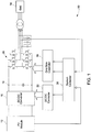
- FIG. 1 illustrates a conventional solar power generation system 10.
- the power generation system includes a PV module 12.
- the PV module is connected to a power grid 14 through a DC/DC converter 16, a DC link 18 and a grid side three-phase DC/AC converter 20.
- the DC/AC converter 20 maintains a constant DC voltage at the DC link 18, and thus the energy flow from the DC-LINK 18 to the power grid 14 is managed.
- the DC/DC converter 16 is controlled by a controller 22, and the grid side converter 20 is controlled by a grid side controller 24.
- a system controller 26 generates a reference DC voltage command, a reference output voltage magnitude command, and a reference frequency command for the DC/DC converter 22 and grid side converter 20.
- the grid side three-phase converter may be replaced by multiple single-phase converters and/or a single controller may be used for the multiple control functions shown in FIG. 1 .
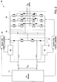
- FIG. 2 illustrates a solar power generation system 40 in accordance with an embodiment of the present invention.
- the system includes a PV module 12, a boost converter 42, a bypass circuit 44, a split DC link 46, a multilevel three phase inverter 48, a boost side maximum power point controller (MPPT) controller 50 and an inverter side MPPT controller 52.
- a grid voltage Vac generally determines the minimum DC link voltage. As long as the DC link voltage is higher than a threshold value or a threshold voltage, typically set by the maximum peak line-to-line voltage, the current injected into the grid by the multilevel inverter 48 will have a sinusoidal waveform.
- the boost side MPPT controller 50 is used to determine a maximum power point for the current-voltage (I-V) characteristics of the PV module and to provide a switching signal to the boost converter to operate the module close to that point at all times.
- the boost converter is used to raise the DC link voltage to make it at least equal to the threshold voltage so as to extract maximum power from the PV module.
- the MPPT controller 50 utilizes a perturbation and observation method.
- the perturbation and observation method the current drawn from the solar array is perturbed and the power change is observed. If the perturbation results in an increase in power, the subsequent perturbation is made in the same direction and vice versa.
- the bypass circuit 44 bypasses the boost converter.
- the boost converter is bypassed when the DC voltage at the photovoltaic (PV) module is higher than the minimum voltage at the split DC link.
- the bypass circuit comprises a power diode or a voltage controlled switch.
- the power diode comprises a silicon carbide (SiC) diode to further improve efficiency of the solar power generation system.
- the MPPT when the bypass circuit 44 bypasses the boost converter 42, the MPPT is operated on the multilevel inverter 48.
- the inverter side MPPT controller 52 senses the voltages and currents from the PV module and it also receives a signal from the bypass circuit 44 to determine when the circuit 44 is working. If the boost converter is bypassed the controller 52 provides switching command signals to the multilevel inverter 48 such that the multilevel inverter 48 will extract maximum power from the PV module.
- the controllers 50 and 52 may be combined into a single controller.
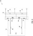
- FIG. 3 illustrates a schematic 60 of a two inductor boost converter along with a split DC link in accordance with an embodiment of the present invention.
- the boost converter 42 includes switching devices 62, 64, the boost inductors 66, 68 and the diodes 70, 72 and 74.
- the switching devices comprise insulated gate bipolar transistors (IGBTs) or power metal oxide semiconductor field effect transistors (MOSFETs).
- IGBTs insulated gate bipolar transistors
- MOSFETs power metal oxide semiconductor field effect transistors
- the switching devices are typically turned on and turned off by a gate drive circuit and in one embodiment comprise silicon carbide devices to improve the efficiency of the circuit.
- the split DC link 46 includes two capacitors 76 and 78. In operation, in one step, the switching devices 62 and 64 are turned on, which causes energy to be stored in the boost inductors 66 and 68.
- the switching device 62 is turned off while the switching device 64 is still on. This step results in charging of the capacitor 76 through the charging path formed by the boost inductor 66, the diode 70, the capacitor 76, the device 64 and the boost inductor 68.
- the switching device 64 is turned off while the device 62 is turned on. This results in charging of the capacitor 78 through the charging path formed by the boost inductor 66, the device 62, the capacitor 78, diode 72 and the boost inductor 68.
- the capacitors 76 and 78 may get charged through the charging path formed by the boost inductor 66, the diode 70, capacitors 76, 78, the diode 72 and the boost inductor 68.
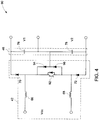
- FIG. 4 illustrates a schematic 90 of another two inductor boost converter and a split DC link in accordance with an embodiment of the present invention.
- a single switching device 92 is used along with two diodes 94 and 96 instead of two switching devices 62 and 64 as in the embodiment of FIG. 3 .
- the device 92 when the device 92 is turned on, the current flows from the boost inductor 66, the device 92 and the boost inductor 68. Thus, storing energy in the two inductors.
- the diodes 70 and 72 block the voltages V1 and V2 respectively.
- the device 92 is turned off, the current flows from the boost inductor 66, the diode 70, capacitors 76 and 78, the diode 72 and the boost inductor 68.
- the capacitors 76 and 78 When the device 92 is turned off, the current flows from the boost inductor 66, the diode 70, capacitors 76 and 78, the diode 72 and the boost inductor
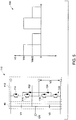
- FIG. 5 illustrates a schematic 110 of one leg or one phase of a diode clamped multilevel inverter and its output waveform in accordance with an embodiment of the present invention.
- the one leg 112 of the multilevel inverter includes four switching devices 114, 116, 118 and 120 and two diodes 122 and 124.
- the voltages V1 and V2 are controlled to maintain at Vdc/2 by the boost converter 42 of FIG. 3 or FIG. 4 and voltage V3 is the phase A voltage.
- the device 114 is complementary of device 118, i.e., when the device 114 is conducting, device 118 is not conducting and vice versa.
- devices 116 and 120 are complementary of each other.
- the one leg of the diode clamped multilevel inverter has three switching stages.
- the first switching stage the devices 114 and 116 are turned on and the devices 118 and 120 are turned off.
- devices 116 and 118 are turned on while devices 112 and 120 are turned off.
- V3 is equal to Vdc/2.
- the output voltage is equal to a voltage at a center tap or a center point 126 of the multilevel converter.
- the center point 126 refers to a connection point between two DC link capacitors.
- the center point voltage may not remain stable and hence voltage V1 and V2 may fluctuate from the value Vdc/2.
- the stability of the center point is controlled by the boost converter; and when the output voltage of the PV module is higher than the threshold voltage, the stability of the center point is controlled by the multi-level converter.
- the multilevel inverter may comprise a flying capacitor inverter comprising a ladder structure of DC capacitors or a cascaded H-bridge inverter, wherein various single phase inverters are connected in series.
- the three-level inverter 112 of FIG. 5 can be increased to any level depending on the circuit topology and thus depending on number of devices and diodes in the circuit. As the number of levels in the inverter increase, the output waveform of the inverter approaches a pure sine wave, resulting in lower harmonics in the output voltage.
- multilevel inverter are the dv/dt stresses on the passive devices, such as inductors, are reduced due to the small increment in voltage steps, reduced electromagnetic compatibility, smaller rating of switching devices and filter components and better feature of output voltage in term of less distortion, lower harmonics contents and lower switching losses.
Landscapes
- Engineering & Computer Science (AREA)
- Power Engineering (AREA)
- General Physics & Mathematics (AREA)
- Life Sciences & Earth Sciences (AREA)
- Sustainable Development (AREA)
- Sustainable Energy (AREA)
- Physics & Mathematics (AREA)
- Electromagnetism (AREA)
- Condensed Matter Physics & Semiconductors (AREA)
- Computer Hardware Design (AREA)
- Microelectronics & Electronic Packaging (AREA)
- Radar, Positioning & Navigation (AREA)
- Automation & Control Theory (AREA)
- Inverter Devices (AREA)
Applications Claiming Priority (1)
| Application Number | Priority Date | Filing Date | Title |
|---|---|---|---|
| US12/473,700 US8184460B2 (en) | 2009-05-28 | 2009-05-28 | Solar inverter and control method |
Publications (2)
| Publication Number | Publication Date |
|---|---|
| EP2256579A1 EP2256579A1 (en) | 2010-12-01 |
| EP2256579B1 true EP2256579B1 (en) | 2017-09-27 |
Family
ID=42289553
Family Applications (1)
| Application Number | Title | Priority Date | Filing Date |
|---|---|---|---|
| EP10163331.1A Active EP2256579B1 (en) | 2009-05-28 | 2010-05-19 | Solar inverter and control method |
Country Status (4)
| Country | Link |
|---|---|
| US (1) | US8184460B2 (zh) |
| EP (1) | EP2256579B1 (zh) |
| CN (1) | CN101902145B (zh) |
| AU (1) | AU2010202078B2 (zh) |
Families Citing this family (133)
| Publication number | Priority date | Publication date | Assignee | Title |
|---|---|---|---|---|
| US11881814B2 (en) | 2005-12-05 | 2024-01-23 | Solaredge Technologies Ltd. | Testing of a photovoltaic panel |
| US10693415B2 (en) | 2007-12-05 | 2020-06-23 | Solaredge Technologies Ltd. | Testing of a photovoltaic panel |
| GB2454389B (en) | 2006-01-13 | 2009-08-26 | Enecsys Ltd | Power conditioning unit |
| US8405367B2 (en) | 2006-01-13 | 2013-03-26 | Enecsys Limited | Power conditioning units |
| US11728768B2 (en) | 2006-12-06 | 2023-08-15 | Solaredge Technologies Ltd. | Pairing of components in a direct current distributed power generation system |
| US9112379B2 (en) | 2006-12-06 | 2015-08-18 | Solaredge Technologies Ltd. | Pairing of components in a direct current distributed power generation system |
| US8013472B2 (en) | 2006-12-06 | 2011-09-06 | Solaredge, Ltd. | Method for distributed power harvesting using DC power sources |
| US8319483B2 (en) | 2007-08-06 | 2012-11-27 | Solaredge Technologies Ltd. | Digital average input current control in power converter |
| US8473250B2 (en) | 2006-12-06 | 2013-06-25 | Solaredge, Ltd. | Monitoring of distributed power harvesting systems using DC power sources |
| US11309832B2 (en) | 2006-12-06 | 2022-04-19 | Solaredge Technologies Ltd. | Distributed power harvesting systems using DC power sources |
| US11888387B2 (en) | 2006-12-06 | 2024-01-30 | Solaredge Technologies Ltd. | Safety mechanisms, wake up and shutdown methods in distributed power installations |
| US8963369B2 (en) | 2007-12-04 | 2015-02-24 | Solaredge Technologies Ltd. | Distributed power harvesting systems using DC power sources |
| US11569659B2 (en) | 2006-12-06 | 2023-01-31 | Solaredge Technologies Ltd. | Distributed power harvesting systems using DC power sources |
| US8319471B2 (en) | 2006-12-06 | 2012-11-27 | Solaredge, Ltd. | Battery power delivery module |
| US8947194B2 (en) | 2009-05-26 | 2015-02-03 | Solaredge Technologies Ltd. | Theft detection and prevention in a power generation system |
| US8618692B2 (en) | 2007-12-04 | 2013-12-31 | Solaredge Technologies Ltd. | Distributed power system using direct current power sources |
| WO2009073868A1 (en) | 2007-12-05 | 2009-06-11 | Solaredge, Ltd. | Safety mechanisms, wake up and shutdown methods in distributed power installations |
| US8816535B2 (en) | 2007-10-10 | 2014-08-26 | Solaredge Technologies, Ltd. | System and method for protection during inverter shutdown in distributed power installations |
| US9088178B2 (en) | 2006-12-06 | 2015-07-21 | Solaredge Technologies Ltd | Distributed power harvesting systems using DC power sources |
| US9130401B2 (en) | 2006-12-06 | 2015-09-08 | Solaredge Technologies Ltd. | Distributed power harvesting systems using DC power sources |
| US11855231B2 (en) | 2006-12-06 | 2023-12-26 | Solaredge Technologies Ltd. | Distributed power harvesting systems using DC power sources |
| US11296650B2 (en) | 2006-12-06 | 2022-04-05 | Solaredge Technologies Ltd. | System and method for protection during inverter shutdown in distributed power installations |
| US11735910B2 (en) | 2006-12-06 | 2023-08-22 | Solaredge Technologies Ltd. | Distributed power system using direct current power sources |
| US8384243B2 (en) | 2007-12-04 | 2013-02-26 | Solaredge Technologies Ltd. | Distributed power harvesting systems using DC power sources |
| US11687112B2 (en) | 2006-12-06 | 2023-06-27 | Solaredge Technologies Ltd. | Distributed power harvesting systems using DC power sources |
| EP2232690B1 (en) | 2007-12-05 | 2016-08-31 | Solaredge Technologies Ltd. | Parallel connected inverters |
| US11264947B2 (en) | 2007-12-05 | 2022-03-01 | Solaredge Technologies Ltd. | Testing of a photovoltaic panel |
| US8049523B2 (en) | 2007-12-05 | 2011-11-01 | Solaredge Technologies Ltd. | Current sensing on a MOSFET |
| EP2722979B1 (en) | 2008-03-24 | 2022-11-30 | Solaredge Technologies Ltd. | Switch mode converter including auxiliary commutation circuit for achieving zero current switching |
| WO2009136358A1 (en) | 2008-05-05 | 2009-11-12 | Solaredge Technologies Ltd. | Direct current power combiner |
| FR2952482B1 (fr) * | 2009-11-06 | 2011-11-18 | Mge Ups Systems | Dispositif convertisseur comprenant au moins cinq niveaux de tension continue et alimentation sans interruption pourvue dudit dispositif. |
| US8710699B2 (en) | 2009-12-01 | 2014-04-29 | Solaredge Technologies Ltd. | Dual use photovoltaic system |
| KR101094002B1 (ko) * | 2009-12-16 | 2011-12-15 | 삼성에스디아이 주식회사 | 전원 변환 장치 |
| US8766696B2 (en) | 2010-01-27 | 2014-07-01 | Solaredge Technologies Ltd. | Fast voltage level shifter circuit |
| US9142960B2 (en) * | 2010-02-03 | 2015-09-22 | Draker, Inc. | Constraint weighted regulation of DC/DC converters |
| JP5521112B2 (ja) * | 2010-04-19 | 2014-06-11 | パワー−ワン イタリイ ソチエタ ペル アチオーニ | マルチレベルdc・acコンバータ |
| US8390261B2 (en) | 2010-05-21 | 2013-03-05 | Infineon Technologies Austria Ag | Maximum power point tracker bypass |
| KR101106413B1 (ko) * | 2010-06-14 | 2012-01-17 | 삼성에스디아이 주식회사 | 에너지 저장 시스템의 인버터 |
| US8772965B2 (en) * | 2010-06-29 | 2014-07-08 | General Electric Company | Solar power generation system and method |
| EP2410648A1 (en) * | 2010-07-20 | 2012-01-25 | Vincotech Holdings S.a.r.l. | DC/DC converter circuit and method for controlling a DC/DC converter circuit |
| US9350166B2 (en) | 2010-10-05 | 2016-05-24 | Alencon Acquisition Co., Llc | High voltage energy harvesting and conversion renewable energy utility size electric power systems and visual monitoring and control systems for said systems |
| US9118215B2 (en) | 2010-10-05 | 2015-08-25 | Alencon Acquistion Co., Llc | High voltage energy harvesting and conversion renewable energy utility size electric power systems and visual monitoring and control systems for said systems |
| US10673222B2 (en) | 2010-11-09 | 2020-06-02 | Solaredge Technologies Ltd. | Arc detection and prevention in a power generation system |
| US10673229B2 (en) | 2010-11-09 | 2020-06-02 | Solaredge Technologies Ltd. | Arc detection and prevention in a power generation system |
| US10230310B2 (en) | 2016-04-05 | 2019-03-12 | Solaredge Technologies Ltd | Safety switch for photovoltaic systems |
| GB2485527B (en) | 2010-11-09 | 2012-12-19 | Solaredge Technologies Ltd | Arc detection and prevention in a power generation system |
| GB2486408A (en) | 2010-12-09 | 2012-06-20 | Solaredge Technologies Ltd | Disconnection of a string carrying direct current |
| US8259479B2 (en) * | 2010-12-21 | 2012-09-04 | General Electric Company | Methods and systems for operating a two-stage power converter |
| GB2496140B (en) | 2011-11-01 | 2016-05-04 | Solarcity Corp | Photovoltaic power conditioning units |
| GB2483317B (en) | 2011-01-12 | 2012-08-22 | Solaredge Technologies Ltd | Serially connected inverters |
| GB2487368B (en) * | 2011-01-18 | 2012-12-05 | Enecsys Ltd | Inverters |
| FR2976405B1 (fr) * | 2011-06-08 | 2014-04-04 | Commissariat Energie Atomique | Dispositif de generation d'energie photovoltaique avec gestion individuelle des cellules |
| WO2012149387A1 (en) * | 2011-04-27 | 2012-11-01 | Solarbridge Technologies, Inc. | Configurable power supply assembly |
| US8174856B2 (en) | 2011-04-27 | 2012-05-08 | Solarbridge Technologies, Inc. | Configurable power supply assembly |
| US11901810B2 (en) | 2011-05-08 | 2024-02-13 | Koolbridge Solar, Inc. | Adaptive electrical power distribution panel |
| US11460488B2 (en) | 2017-08-14 | 2022-10-04 | Koolbridge Solar, Inc. | AC electrical power measurements |
| US8937822B2 (en) | 2011-05-08 | 2015-01-20 | Paul Wilkinson Dent | Solar energy conversion and utilization system |
| AU2012253314B2 (en) * | 2011-05-12 | 2016-11-24 | Alencon Acquisition Co., Llc | High voltage energy harvesting and conversion renewable energy utility size electric power systems and visual monitoring and control systems |
| US8842397B2 (en) * | 2011-05-23 | 2014-09-23 | Microsemi Corporation | Photo-voltaic safety de-energizing device |
| KR101906895B1 (ko) * | 2011-06-08 | 2018-10-11 | 엘에스산전 주식회사 | 태양광 전력 변환 장치 |
| JP2014523225A (ja) * | 2011-07-08 | 2014-09-08 | エスエムエー ソーラー テクノロジー アーゲー | Dc/acコンバータ、発電プラント、および、dc/acコンバータのための動作方法 |
| US8570005B2 (en) | 2011-09-12 | 2013-10-29 | Solaredge Technologies Ltd. | Direct current link circuit |
| US9537420B2 (en) | 2011-09-21 | 2017-01-03 | Enphase Energy, Inc. | Method and apparatus for power module output power regulation |
| US8624411B2 (en) | 2011-10-14 | 2014-01-07 | General Electric Company | Power generation system including predictive control apparatus to reduce influences of weather-varying factors |
| GB2496139B (en) | 2011-11-01 | 2016-05-04 | Solarcity Corp | Photovoltaic power conditioning units |
| CN102403920B (zh) * | 2011-11-16 | 2014-05-14 | 广东易事特电源股份有限公司 | 三电平半桥光伏并网逆变器 |
| TW201328118A (zh) * | 2011-12-28 | 2013-07-01 | Hon Hai Prec Ind Co Ltd | 不間斷電源系統 |
| CN103186160B (zh) * | 2011-12-31 | 2015-02-11 | 上海亿福新能源技术有限公司 | 一种光伏发电最大功率点跟踪的自调节控制方法 |
| GB2498365A (en) | 2012-01-11 | 2013-07-17 | Solaredge Technologies Ltd | Photovoltaic module |
| GB2498790A (en) | 2012-01-30 | 2013-07-31 | Solaredge Technologies Ltd | Maximising power in a photovoltaic distributed power system |
| GB2498791A (en) | 2012-01-30 | 2013-07-31 | Solaredge Technologies Ltd | Photovoltaic panel circuitry |
| US9853565B2 (en) | 2012-01-30 | 2017-12-26 | Solaredge Technologies Ltd. | Maximized power in a photovoltaic distributed power system |
| US20130200709A1 (en) * | 2012-02-03 | 2013-08-08 | International Business Machines Corporation | Techniques for Grid Coupling Photovoltaic Cells Using Ratiometric Voltage Conversion |
| GB2499991A (en) | 2012-03-05 | 2013-09-11 | Solaredge Technologies Ltd | DC link circuit for photovoltaic array |
| US8885373B1 (en) * | 2012-03-07 | 2014-11-11 | Power-One Italy S.pA. | Earth leakage current control for a multi-level grounded inverter |
| US9413268B2 (en) * | 2012-05-10 | 2016-08-09 | Futurewei Technologies, Inc. | Multilevel inverter device and method |
| EP2859650B1 (en) | 2012-05-25 | 2017-02-15 | Solaredge Technologies Ltd. | Circuit for interconnected direct current power sources |
| KR20130133413A (ko) * | 2012-05-29 | 2013-12-09 | 엘에스산전 주식회사 | 태양광 발전 장치 |
| US10115841B2 (en) | 2012-06-04 | 2018-10-30 | Solaredge Technologies Ltd. | Integrated photovoltaic panel circuitry |
| US20140049998A1 (en) * | 2012-08-16 | 2014-02-20 | Leo F. Casey | DC to AC Power Converter |
| US20140070614A1 (en) * | 2012-09-07 | 2014-03-13 | Atomic Energy Council-Institute Of Nuclear Energy Research | Household Grid-Connected Inverter Applied to Solar Power Generation System with Maximum Power Tracking Function |
| WO2014045125A2 (en) | 2012-09-18 | 2014-03-27 | Ge Energy Power Conversion Technology Ltd | System and method for providing periodic electrical isolation in a power system such as a solar power generation system |
| CN202817839U (zh) * | 2012-09-21 | 2013-03-20 | 纽福克斯光电科技(上海)有限公司 | 一种应急启动机动车电路 |
| US9557758B2 (en) | 2012-10-16 | 2017-01-31 | Volterra Semiconductor LLC | Systems and methods for controlling maximum power point tracking controllers |
| US9941813B2 (en) | 2013-03-14 | 2018-04-10 | Solaredge Technologies Ltd. | High frequency multi-level inverter |
| US9548619B2 (en) | 2013-03-14 | 2017-01-17 | Solaredge Technologies Ltd. | Method and apparatus for storing and depleting energy |
| EP4318001A3 (en) | 2013-03-15 | 2024-05-01 | Solaredge Technologies Ltd. | Bypass mechanism |
| WO2014144552A1 (en) * | 2013-03-15 | 2014-09-18 | Advanced Geosciences, Inc. | High power current switch |
| WO2014147771A1 (ja) * | 2013-03-20 | 2014-09-25 | 富士電機株式会社 | 太陽光発電システム |
| WO2014154390A1 (en) | 2013-03-26 | 2014-10-02 | Telefonaktiebolaget L M Ericsson (Publ) | A voltage modulator |
| WO2014182818A1 (en) * | 2013-05-07 | 2014-11-13 | University Of Central Florida Research Foundation, Inc. | Variable frequency iteration mppt for resonant power converters |
| US9270164B2 (en) | 2013-06-19 | 2016-02-23 | Tmeic Corporation | Methods, systems, computer program products, and devices for renewable energy site power limit control |
| GB201312621D0 (en) * | 2013-07-15 | 2013-08-28 | Univ Plymouth | Control arrangement |
| CN105431992B (zh) * | 2013-07-23 | 2019-01-15 | 东芝三菱电机产业系统株式会社 | 太阳能发电用逆变器的控制装置 |
| US9647571B2 (en) * | 2013-08-02 | 2017-05-09 | Solantro Semiconductor Corp. | Internal inverter communications |
| US9337748B2 (en) * | 2013-08-02 | 2016-05-10 | Infineon Technologies Austria Ag | System and method for a DC-to-DC power converter with inverter stage coupled to the DC input |
| KR101741075B1 (ko) * | 2013-09-02 | 2017-05-29 | 엘에스산전 주식회사 | 태양광 인버터 |
| ITBZ20130050A1 (it) * | 2013-10-10 | 2015-04-11 | Sunforlife S R L | Ottimizzatore per stringhe fotovoltaiche, tramite metodo innovativo di condivisione della carica che agisce in parallelo alle stringhe ovvero preservandone l'originale collegamento serie |
| US9728974B2 (en) | 2013-10-10 | 2017-08-08 | Tmeic Corporation | Renewable energy site reactive power control |
| EP3061174B1 (en) | 2013-10-21 | 2018-04-25 | ABB Schweiz AG | Double-stage inverter apparatus for energy conversion systems and control method thereof |
| US9318974B2 (en) | 2014-03-26 | 2016-04-19 | Solaredge Technologies Ltd. | Multi-level inverter with flying capacitor topology |
| US9555711B2 (en) * | 2014-06-03 | 2017-01-31 | Hamilton Sundstrand Corporation | Power converters |
| CN104038036B (zh) * | 2014-06-30 | 2016-08-24 | 阳光电源股份有限公司 | 悬浮电压抑制方法、装置、逆变器控制系统及其逆变器 |
| CN104158208A (zh) * | 2014-07-15 | 2014-11-19 | 阳光电源股份有限公司 | 一种单级光伏并网逆变器及其控制方法和应用 |
| CN104269914A (zh) * | 2014-10-15 | 2015-01-07 | 四川东方电气自动控制工程有限公司 | 一种风光互补控制逆变一体机 |
| CN104377977A (zh) * | 2014-12-08 | 2015-02-25 | 国家电网公司 | 一种三电平逆变器及其控制方法 |
| US9912151B2 (en) * | 2015-01-23 | 2018-03-06 | General Electric Company | Direct current power system |
| US9806601B2 (en) * | 2015-03-27 | 2017-10-31 | Futurewei Technologies, Inc. | Boost converter and method |
| CN105048854A (zh) * | 2015-07-21 | 2015-11-11 | 珠海格力电器股份有限公司 | 三相非隔离并网变换器及空调系统 |
| GB201513549D0 (en) * | 2015-07-31 | 2015-09-16 | Siemens Ag | Inverter |
| CN105186901B (zh) * | 2015-09-06 | 2017-10-27 | 阳光电源股份有限公司 | 一种五电平逆变器输入电压控制方法及装置 |
| US10938218B2 (en) | 2015-12-28 | 2021-03-02 | Sunpower Corporation | Solar tracker system |
| CN105490302B (zh) * | 2016-01-22 | 2018-03-13 | 国家电网公司 | 一种无需交直流电流传感器的多电平光伏逆变装置 |
| CN105490303B (zh) * | 2016-01-22 | 2018-10-16 | 国家电网公司 | 一种无需交直流电流传感器的多电平储能功率转换控制装置 |
| CN105515513B (zh) * | 2016-01-29 | 2018-08-03 | 阳光电源股份有限公司 | 一种光伏逆变器及其控制方法 |
| CN107153212B (zh) | 2016-03-03 | 2023-07-28 | 太阳能安吉科技有限公司 | 用于映射发电设施的方法 |
| US11081608B2 (en) | 2016-03-03 | 2021-08-03 | Solaredge Technologies Ltd. | Apparatus and method for determining an order of power devices in power generation systems |
| US10599113B2 (en) | 2016-03-03 | 2020-03-24 | Solaredge Technologies Ltd. | Apparatus and method for determining an order of power devices in power generation systems |
| US11177663B2 (en) | 2016-04-05 | 2021-11-16 | Solaredge Technologies Ltd. | Chain of power devices |
| US12057807B2 (en) | 2016-04-05 | 2024-08-06 | Solaredge Technologies Ltd. | Chain of power devices |
| US11018623B2 (en) | 2016-04-05 | 2021-05-25 | Solaredge Technologies Ltd. | Safety switch for photovoltaic systems |
| US10483759B2 (en) | 2016-04-07 | 2019-11-19 | Alencon Acquisition Co., Llc | Integrated multi-mode large-scale electric power support system for an electrical grid |
| US10236690B2 (en) * | 2016-06-30 | 2019-03-19 | Sunpower Corporation | Backfeed power supply for solar power system |
| JP6952245B2 (ja) * | 2016-09-30 | 2021-10-20 | パナソニックIpマネジメント株式会社 | 電力変換システム |
| CN107302319A (zh) * | 2017-06-14 | 2017-10-27 | 珠海格力电器股份有限公司 | 单相正弦波逆变器及其控制方法 |
| CN107317343B (zh) * | 2017-08-24 | 2023-05-12 | 长沙理工大学 | 高效级联h桥型动态电压恢复器及其控制方法 |
| CN110350812B (zh) * | 2018-04-08 | 2024-08-13 | 佛山科学技术学院 | 一种用于ups的逆变器模块 |
| US10516365B1 (en) * | 2018-06-20 | 2019-12-24 | Schneider Electric Solar Inverters Usa, Inc. | DC voltage control in renewable energy based multilevel power converter |
| FR3084798B1 (fr) * | 2018-08-03 | 2020-10-30 | Schneider Electric Ind Sas | Convertisseur de puissance multiniveaux |
| US10651739B1 (en) | 2019-02-25 | 2020-05-12 | Nextracker Inc. | Power converters and methods of controlling same |
| CN110994975B (zh) * | 2019-12-18 | 2020-11-10 | 阳光电源股份有限公司 | 一种电容钳位式直流变换电路 |
| WO2022006737A1 (zh) * | 2020-07-07 | 2022-01-13 | 华为数字能源技术有限公司 | 一种电源系统 |
| CN112234649A (zh) * | 2020-10-15 | 2021-01-15 | 珠海格力电器股份有限公司 | 自适应的光伏供电系统及其控制方法、空调机组 |
Citations (5)
| Publication number | Priority date | Publication date | Assignee | Title |
|---|---|---|---|---|
| US5179508A (en) | 1991-10-15 | 1993-01-12 | International Business Machines Corp. | Standby boost converter |
| US20060174939A1 (en) | 2004-12-29 | 2006-08-10 | Isg Technologies Llc | Efficiency booster circuit and technique for maximizing power point tracking |
| US20080238195A1 (en) | 2007-03-27 | 2008-10-02 | Shaver Argil E | Distributed maximum power point tracking system, structure and process |
| US20090121549A1 (en) | 2007-11-14 | 2009-05-14 | General Electric Company | Method and system to convert direct current (dc) to alternating current (ac) using a photovoltaic inverter |
| EP2104200A1 (de) | 2008-03-22 | 2009-09-23 | SMA Solar Technology AG | Verfahren zur Ansteuerung eines Multi-String-Wechselrichters für Photovoltaikanlagen |
Family Cites Families (13)
| Publication number | Priority date | Publication date | Assignee | Title |
|---|---|---|---|---|
| US5389158A (en) * | 1989-04-17 | 1995-02-14 | The Boeing Company | Low bandgap photovoltaic cell with inherent bypass diode |
| US6111767A (en) * | 1998-06-22 | 2000-08-29 | Heliotronics, Inc. | Inverter integrated instrumentation having a current-voltage curve tracer |
| AUPS143902A0 (en) * | 2002-03-28 | 2002-05-09 | Curtin University Of Technology | Power conversion system and method of converting power |
| US7227278B2 (en) * | 2004-01-21 | 2007-06-05 | Nextek Power Systems Inc. | Multiple bi-directional input/output power control system |
| EP1852963B1 (en) * | 2005-02-25 | 2016-04-06 | Mitsubishi Denki Kabushiki Kaisha | Power conversion apparatus |
| US8013472B2 (en) * | 2006-12-06 | 2011-09-06 | Solaredge, Ltd. | Method for distributed power harvesting using DC power sources |
| GB0625121D0 (en) * | 2006-12-18 | 2007-01-24 | Gendrive Ltd | Electrical energy converter |
| US20090000654A1 (en) * | 2007-05-17 | 2009-01-01 | Larankelo, Inc. | Distributed inverter and intelligent gateway |
| US20090014050A1 (en) * | 2007-07-13 | 2009-01-15 | Peter Haaf | Solar module system and method using transistors for bypass |
| CN101350569A (zh) * | 2008-09-03 | 2009-01-21 | 深圳职业技术学院 | 太阳能光伏逆变器拓扑结构 |
| US8334616B2 (en) * | 2008-09-19 | 2012-12-18 | Electric Power Research Institute, Inc. | Photovoltaic integrated variable frequency drive |
| US20100157632A1 (en) * | 2008-12-20 | 2010-06-24 | Azuray Technologies, Inc. | Energy Conversion Systems With Power Control |
| US8400134B2 (en) * | 2009-11-12 | 2013-03-19 | Intersil Americas Inc. | Apparatus and methodology for maximum power point tracking for a solar panel |
-
2009
- 2009-05-28 US US12/473,700 patent/US8184460B2/en active Active
-
2010
- 2010-05-19 EP EP10163331.1A patent/EP2256579B1/en active Active
- 2010-05-21 AU AU2010202078A patent/AU2010202078B2/en active Active
- 2010-05-28 CN CN201010196647.8A patent/CN101902145B/zh active Active
Patent Citations (5)
| Publication number | Priority date | Publication date | Assignee | Title |
|---|---|---|---|---|
| US5179508A (en) | 1991-10-15 | 1993-01-12 | International Business Machines Corp. | Standby boost converter |
| US20060174939A1 (en) | 2004-12-29 | 2006-08-10 | Isg Technologies Llc | Efficiency booster circuit and technique for maximizing power point tracking |
| US20080238195A1 (en) | 2007-03-27 | 2008-10-02 | Shaver Argil E | Distributed maximum power point tracking system, structure and process |
| US20090121549A1 (en) | 2007-11-14 | 2009-05-14 | General Electric Company | Method and system to convert direct current (dc) to alternating current (ac) using a photovoltaic inverter |
| EP2104200A1 (de) | 2008-03-22 | 2009-09-23 | SMA Solar Technology AG | Verfahren zur Ansteuerung eines Multi-String-Wechselrichters für Photovoltaikanlagen |
Non-Patent Citations (2)
| Title |
|---|
| PRADEEP M BHAGWAT; STEFANOVIC V R: "Generalized Structure of a Mulitilevel PWM inverfer", IEEE TRANSACTIONS ON INDUSTRY APPLICATIONS, no. 6, November 1983 (1983-11-01), pages 1057 - 1069, XP011213275 |
| SMA SOLAR TECHNOLOGY AG: "PV-Wechselrichter SUNNY BOY 3000TL/ 4000TL/ 5000TL Installationsanleitung", pages 1 - 76, XP002593870 |
Also Published As
| Publication number | Publication date |
|---|---|
| US8184460B2 (en) | 2012-05-22 |
| US20100302819A1 (en) | 2010-12-02 |
| CN101902145B (zh) | 2016-06-01 |
| EP2256579A1 (en) | 2010-12-01 |
| AU2010202078A1 (en) | 2010-12-16 |
| AU2010202078B2 (en) | 2015-07-23 |
| CN101902145A (zh) | 2010-12-01 |
Similar Documents
| Publication | Publication Date | Title |
|---|---|---|
| EP2256579B1 (en) | Solar inverter and control method | |
| EP2323248B1 (en) | Operation of a three level converter | |
| Iman-Eini et al. | A modular strategy for control and voltage balancing of cascaded H-bridge rectifiers | |
| US7099169B2 (en) | DC to AC inverter with single-switch bipolar boost circuit | |
| US20040164557A1 (en) | Monopolar dc to bipolar to ac converter | |
| Kurdkandi et al. | A new transformer-less common grounded three-level grid-tied inverter with voltage boosting capability | |
| Elkhateb et al. | The effect of input current ripple on the photovoltaic panel efficiency | |
| Kumar et al. | T-shaped Z-source inverter | |
| Chen et al. | A dual-input central capacitor DC/DC converter for distributed photovoltaic architectures | |
| Zhang et al. | Two-stage transformerless dual-buck PV grid-connected inverters with high efficiency | |
| Huynh et al. | Switched-capacitor-inductor active-switched boost inverters with high boost ability | |
| Lorenzani et al. | Performance analysis of a modified Current Source Inverter for photovoltaic microinverter applications | |
| Banaei | Multi-stage DC-AC converter based on new DC-DC converter for energy conversion | |
| US9325273B2 (en) | Method and system for driving electric machines | |
| Radhika et al. | A novel photovoltaic power harvesting system using a transformerless H6 single-phase inverter with improved grid current quality | |
| Rasekh et al. | Design and analysis of high gain DC-DC boost converter for grid connected solar photovoltaic system | |
| Zhang et al. | A novel impedance-network-based electric spring | |
| Junior et al. | Evaluation of integrated inverter topologies for low power PV systems | |
| Saradhi et al. | A Novel Control Technique for Single-Phase five Level Inverter for a Grid-Connected Photovoltaic System | |
| Selvabharathi et al. | Simulation of zeta converter based 3-level NPC inverter with PV system | |
| Shah et al. | An MPPT-based 31-Level ADC Controlled Micro-Inverter | |
| Alemi et al. | Performance analysis of high‐power three‐phase current source inverters in photovoltaic applications | |
| Neti et al. | Common Ground Single-Phase Single-Stage Transformerless Inverter Five Levels Using Reduced Components and Switched Capacitor Cell | |
| Muthukaruppasamy et al. | A Symmetric Multi-Level Cascaded H-Bridge Inverter for Renewable Energy Integration | |
| Ross | System electronics |
Legal Events
| Date | Code | Title | Description |
|---|---|---|---|
| PUAI | Public reference made under article 153(3) epc to a published international application that has entered the european phase |
Free format text: ORIGINAL CODE: 0009012 |
|
| AK | Designated contracting states |
Kind code of ref document: A1 Designated state(s): AL AT BE BG CH CY CZ DE DK EE ES FI FR GB GR HR HU IE IS IT LI LT LU LV MC MK MT NL NO PL PT RO SE SI SK SM TR |
|
| AX | Request for extension of the european patent |
Extension state: BA ME RS |
|
| 17P | Request for examination filed |
Effective date: 20110601 |
|
| REG | Reference to a national code |
Ref country code: DE Ref legal event code: R079 Ref document number: 602010045500 Country of ref document: DE Free format text: PREVIOUS MAIN CLASS: G05F0001670000 Ipc: H01L0031020000 |
|
| GRAP | Despatch of communication of intention to grant a patent |
Free format text: ORIGINAL CODE: EPIDOSNIGR1 |
|
| STAA | Information on the status of an ep patent application or granted ep patent |
Free format text: STATUS: GRANT OF PATENT IS INTENDED |
|
| RIC1 | Information provided on ipc code assigned before grant |
Ipc: H02M 1/00 20070101ALI20170322BHEP Ipc: H02J 3/38 20060101ALI20170322BHEP Ipc: H02M 7/487 20070101ALI20170322BHEP Ipc: G05F 1/67 20060101ALI20170322BHEP Ipc: H01L 31/02 20060101AFI20170322BHEP |
|
| INTG | Intention to grant announced |
Effective date: 20170407 |
|
| TPAC | Observations filed by third parties |
Free format text: ORIGINAL CODE: EPIDOSNTIPA |
|
| GRAS | Grant fee paid |
Free format text: ORIGINAL CODE: EPIDOSNIGR3 |
|
| GRAA | (expected) grant |
Free format text: ORIGINAL CODE: 0009210 |
|
| STAA | Information on the status of an ep patent application or granted ep patent |
Free format text: STATUS: THE PATENT HAS BEEN GRANTED |
|
| AK | Designated contracting states |
Kind code of ref document: B1 Designated state(s): AL AT BE BG CH CY CZ DE DK EE ES FI FR GB GR HR HU IE IS IT LI LT LU LV MC MK MT NL NO PL PT RO SE SI SK SM TR |
|
| REG | Reference to a national code |
Ref country code: GB Ref legal event code: FG4D |
|
| REG | Reference to a national code |
Ref country code: CH Ref legal event code: EP |
|
| REG | Reference to a national code |
Ref country code: AT Ref legal event code: REF Ref document number: 932741 Country of ref document: AT Kind code of ref document: T Effective date: 20171015 |
|
| REG | Reference to a national code |
Ref country code: IE Ref legal event code: FG4D |
|
| REG | Reference to a national code |
Ref country code: DE Ref legal event code: R096 Ref document number: 602010045500 Country of ref document: DE |
|
| PG25 | Lapsed in a contracting state [announced via postgrant information from national office to epo] |
Ref country code: NO Free format text: LAPSE BECAUSE OF FAILURE TO SUBMIT A TRANSLATION OF THE DESCRIPTION OR TO PAY THE FEE WITHIN THE PRESCRIBED TIME-LIMIT Effective date: 20171227 Ref country code: SE Free format text: LAPSE BECAUSE OF FAILURE TO SUBMIT A TRANSLATION OF THE DESCRIPTION OR TO PAY THE FEE WITHIN THE PRESCRIBED TIME-LIMIT Effective date: 20170927 Ref country code: HR Free format text: LAPSE BECAUSE OF FAILURE TO SUBMIT A TRANSLATION OF THE DESCRIPTION OR TO PAY THE FEE WITHIN THE PRESCRIBED TIME-LIMIT Effective date: 20170927 Ref country code: LT Free format text: LAPSE BECAUSE OF FAILURE TO SUBMIT A TRANSLATION OF THE DESCRIPTION OR TO PAY THE FEE WITHIN THE PRESCRIBED TIME-LIMIT Effective date: 20170927 Ref country code: FI Free format text: LAPSE BECAUSE OF FAILURE TO SUBMIT A TRANSLATION OF THE DESCRIPTION OR TO PAY THE FEE WITHIN THE PRESCRIBED TIME-LIMIT Effective date: 20170927 |
|
| REG | Reference to a national code |
Ref country code: NL Ref legal event code: MP Effective date: 20170927 |
|
| REG | Reference to a national code |
Ref country code: LT Ref legal event code: MG4D |
|
| REG | Reference to a national code |
Ref country code: AT Ref legal event code: MK05 Ref document number: 932741 Country of ref document: AT Kind code of ref document: T Effective date: 20170927 |
|
| PG25 | Lapsed in a contracting state [announced via postgrant information from national office to epo] |
Ref country code: BG Free format text: LAPSE BECAUSE OF FAILURE TO SUBMIT A TRANSLATION OF THE DESCRIPTION OR TO PAY THE FEE WITHIN THE PRESCRIBED TIME-LIMIT Effective date: 20171227 Ref country code: LV Free format text: LAPSE BECAUSE OF FAILURE TO SUBMIT A TRANSLATION OF THE DESCRIPTION OR TO PAY THE FEE WITHIN THE PRESCRIBED TIME-LIMIT Effective date: 20170927 Ref country code: GR Free format text: LAPSE BECAUSE OF FAILURE TO SUBMIT A TRANSLATION OF THE DESCRIPTION OR TO PAY THE FEE WITHIN THE PRESCRIBED TIME-LIMIT Effective date: 20171228 |
|
| PG25 | Lapsed in a contracting state [announced via postgrant information from national office to epo] |
Ref country code: NL Free format text: LAPSE BECAUSE OF FAILURE TO SUBMIT A TRANSLATION OF THE DESCRIPTION OR TO PAY THE FEE WITHIN THE PRESCRIBED TIME-LIMIT Effective date: 20170927 |
|
| PG25 | Lapsed in a contracting state [announced via postgrant information from national office to epo] |
Ref country code: RO Free format text: LAPSE BECAUSE OF FAILURE TO SUBMIT A TRANSLATION OF THE DESCRIPTION OR TO PAY THE FEE WITHIN THE PRESCRIBED TIME-LIMIT Effective date: 20170927 Ref country code: ES Free format text: LAPSE BECAUSE OF FAILURE TO SUBMIT A TRANSLATION OF THE DESCRIPTION OR TO PAY THE FEE WITHIN THE PRESCRIBED TIME-LIMIT Effective date: 20170927 Ref country code: CZ Free format text: LAPSE BECAUSE OF FAILURE TO SUBMIT A TRANSLATION OF THE DESCRIPTION OR TO PAY THE FEE WITHIN THE PRESCRIBED TIME-LIMIT Effective date: 20170927 |
|
| PG25 | Lapsed in a contracting state [announced via postgrant information from national office to epo] |
Ref country code: IT Free format text: LAPSE BECAUSE OF FAILURE TO SUBMIT A TRANSLATION OF THE DESCRIPTION OR TO PAY THE FEE WITHIN THE PRESCRIBED TIME-LIMIT Effective date: 20170927 Ref country code: SK Free format text: LAPSE BECAUSE OF FAILURE TO SUBMIT A TRANSLATION OF THE DESCRIPTION OR TO PAY THE FEE WITHIN THE PRESCRIBED TIME-LIMIT Effective date: 20170927 Ref country code: IS Free format text: LAPSE BECAUSE OF FAILURE TO SUBMIT A TRANSLATION OF THE DESCRIPTION OR TO PAY THE FEE WITHIN THE PRESCRIBED TIME-LIMIT Effective date: 20180127 Ref country code: SM Free format text: LAPSE BECAUSE OF FAILURE TO SUBMIT A TRANSLATION OF THE DESCRIPTION OR TO PAY THE FEE WITHIN THE PRESCRIBED TIME-LIMIT Effective date: 20170927 Ref country code: AT Free format text: LAPSE BECAUSE OF FAILURE TO SUBMIT A TRANSLATION OF THE DESCRIPTION OR TO PAY THE FEE WITHIN THE PRESCRIBED TIME-LIMIT Effective date: 20170927 Ref country code: EE Free format text: LAPSE BECAUSE OF FAILURE TO SUBMIT A TRANSLATION OF THE DESCRIPTION OR TO PAY THE FEE WITHIN THE PRESCRIBED TIME-LIMIT Effective date: 20170927 |
|
| REG | Reference to a national code |
Ref country code: DE Ref legal event code: R026 Ref document number: 602010045500 Country of ref document: DE |
|
| PLBI | Opposition filed |
Free format text: ORIGINAL CODE: 0009260 |
|
| PLAX | Notice of opposition and request to file observation + time limit sent |
Free format text: ORIGINAL CODE: EPIDOSNOBS2 |
|
| PG25 | Lapsed in a contracting state [announced via postgrant information from national office to epo] |
Ref country code: DK Free format text: LAPSE BECAUSE OF FAILURE TO SUBMIT A TRANSLATION OF THE DESCRIPTION OR TO PAY THE FEE WITHIN THE PRESCRIBED TIME-LIMIT Effective date: 20170927 |
|
| 26 | Opposition filed |
Opponent name: SMA SOLAR TECHNOLOGY AG Effective date: 20180627 |
|
| PG25 | Lapsed in a contracting state [announced via postgrant information from national office to epo] |
Ref country code: PL Free format text: LAPSE BECAUSE OF FAILURE TO SUBMIT A TRANSLATION OF THE DESCRIPTION OR TO PAY THE FEE WITHIN THE PRESCRIBED TIME-LIMIT Effective date: 20170927 |
|
| PLBB | Reply of patent proprietor to notice(s) of opposition received |
Free format text: ORIGINAL CODE: EPIDOSNOBS3 |
|
| PG25 | Lapsed in a contracting state [announced via postgrant information from national office to epo] |
Ref country code: SI Free format text: LAPSE BECAUSE OF FAILURE TO SUBMIT A TRANSLATION OF THE DESCRIPTION OR TO PAY THE FEE WITHIN THE PRESCRIBED TIME-LIMIT Effective date: 20170927 |
|
| REG | Reference to a national code |
Ref country code: CH Ref legal event code: PL |
|
| REG | Reference to a national code |
Ref country code: BE Ref legal event code: MM Effective date: 20180531 |
|
| PG25 | Lapsed in a contracting state [announced via postgrant information from national office to epo] |
Ref country code: MC Free format text: LAPSE BECAUSE OF FAILURE TO SUBMIT A TRANSLATION OF THE DESCRIPTION OR TO PAY THE FEE WITHIN THE PRESCRIBED TIME-LIMIT Effective date: 20170927 |
|
| REG | Reference to a national code |
Ref country code: IE Ref legal event code: MM4A |
|
| PG25 | Lapsed in a contracting state [announced via postgrant information from national office to epo] |
Ref country code: LI Free format text: LAPSE BECAUSE OF NON-PAYMENT OF DUE FEES Effective date: 20180531 Ref country code: CH Free format text: LAPSE BECAUSE OF NON-PAYMENT OF DUE FEES Effective date: 20180531 |
|
| PG25 | Lapsed in a contracting state [announced via postgrant information from national office to epo] |
Ref country code: LU Free format text: LAPSE BECAUSE OF NON-PAYMENT OF DUE FEES Effective date: 20180519 |
|
| PG25 | Lapsed in a contracting state [announced via postgrant information from national office to epo] |
Ref country code: IE Free format text: LAPSE BECAUSE OF NON-PAYMENT OF DUE FEES Effective date: 20180519 Ref country code: FR Free format text: LAPSE BECAUSE OF NON-PAYMENT OF DUE FEES Effective date: 20180531 |
|
| PG25 | Lapsed in a contracting state [announced via postgrant information from national office to epo] |
Ref country code: BE Free format text: LAPSE BECAUSE OF NON-PAYMENT OF DUE FEES Effective date: 20180531 |
|
| PG25 | Lapsed in a contracting state [announced via postgrant information from national office to epo] |
Ref country code: MT Free format text: LAPSE BECAUSE OF NON-PAYMENT OF DUE FEES Effective date: 20180519 |
|
| PG25 | Lapsed in a contracting state [announced via postgrant information from national office to epo] |
Ref country code: TR Free format text: LAPSE BECAUSE OF FAILURE TO SUBMIT A TRANSLATION OF THE DESCRIPTION OR TO PAY THE FEE WITHIN THE PRESCRIBED TIME-LIMIT Effective date: 20170927 |
|
| PG25 | Lapsed in a contracting state [announced via postgrant information from national office to epo] |
Ref country code: PT Free format text: LAPSE BECAUSE OF FAILURE TO SUBMIT A TRANSLATION OF THE DESCRIPTION OR TO PAY THE FEE WITHIN THE PRESCRIBED TIME-LIMIT Effective date: 20170927 Ref country code: HU Free format text: LAPSE BECAUSE OF FAILURE TO SUBMIT A TRANSLATION OF THE DESCRIPTION OR TO PAY THE FEE WITHIN THE PRESCRIBED TIME-LIMIT; INVALID AB INITIO Effective date: 20100519 |
|
| PG25 | Lapsed in a contracting state [announced via postgrant information from national office to epo] |
Ref country code: CY Free format text: LAPSE BECAUSE OF FAILURE TO SUBMIT A TRANSLATION OF THE DESCRIPTION OR TO PAY THE FEE WITHIN THE PRESCRIBED TIME-LIMIT Effective date: 20170927 Ref country code: MK Free format text: LAPSE BECAUSE OF NON-PAYMENT OF DUE FEES Effective date: 20170927 |
|
| PG25 | Lapsed in a contracting state [announced via postgrant information from national office to epo] |
Ref country code: AL Free format text: LAPSE BECAUSE OF FAILURE TO SUBMIT A TRANSLATION OF THE DESCRIPTION OR TO PAY THE FEE WITHIN THE PRESCRIBED TIME-LIMIT Effective date: 20170927 |
|
| RDAF | Communication despatched that patent is revoked |
Free format text: ORIGINAL CODE: EPIDOSNREV1 |
|
| APAH | Appeal reference modified |
Free format text: ORIGINAL CODE: EPIDOSCREFNO |
|
| APAJ | Date of receipt of notice of appeal modified |
Free format text: ORIGINAL CODE: EPIDOSCNOA2O |
|
| APBM | Appeal reference recorded |
Free format text: ORIGINAL CODE: EPIDOSNREFNO |
|
| APBP | Date of receipt of notice of appeal recorded |
Free format text: ORIGINAL CODE: EPIDOSNNOA2O |
|
| APBQ | Date of receipt of statement of grounds of appeal recorded |
Free format text: ORIGINAL CODE: EPIDOSNNOA3O |
|
| PLAB | Opposition data, opponent's data or that of the opponent's representative modified |
Free format text: ORIGINAL CODE: 0009299OPPO |
|
| P01 | Opt-out of the competence of the unified patent court (upc) registered |
Effective date: 20230522 |
|
| R26 | Opposition filed (corrected) |
Opponent name: SMA SOLAR TECHNOLOGY AG Effective date: 20180627 |
|
| REG | Reference to a national code |
Ref country code: DE Ref legal event code: R081 Ref document number: 602010045500 Country of ref document: DE Owner name: GE GRID SOLUTIONS LLC, ATLANTA, US Free format text: FORMER OWNER: GENERAL ELECTRIC COMPANY, SCHENECTADY, NY, US |
|
| REG | Reference to a national code |
Ref country code: GB Ref legal event code: 732E Free format text: REGISTERED BETWEEN 20231207 AND 20231213 |
|
| RAP2 | Party data changed (patent owner data changed or rights of a patent transferred) |
Owner name: GE GRID SOLUTIONS LLC |
|
| PGFP | Annual fee paid to national office [announced via postgrant information from national office to epo] |
Ref country code: GB Payment date: 20240419 Year of fee payment: 15 |
|
| PGFP | Annual fee paid to national office [announced via postgrant information from national office to epo] |
Ref country code: DE Payment date: 20240418 Year of fee payment: 15 |