EP2256449A2 - Method for producing a radiator plate, plate radiator body and distancer - Google Patents
Method for producing a radiator plate, plate radiator body and distancer Download PDFInfo
- Publication number
- EP2256449A2 EP2256449A2 EP10163058A EP10163058A EP2256449A2 EP 2256449 A2 EP2256449 A2 EP 2256449A2 EP 10163058 A EP10163058 A EP 10163058A EP 10163058 A EP10163058 A EP 10163058A EP 2256449 A2 EP2256449 A2 EP 2256449A2
- Authority
- EP
- European Patent Office
- Prior art keywords
- spacer
- shells
- heating
- collecting channel
- collecting
- Prior art date
- Legal status (The legal status is an assumption and is not a legal conclusion. Google has not performed a legal analysis and makes no representation as to the accuracy of the status listed.)
- Granted
Links
Images


Classifications
-
- F—MECHANICAL ENGINEERING; LIGHTING; HEATING; WEAPONS; BLASTING
- F28—HEAT EXCHANGE IN GENERAL
- F28F—DETAILS OF HEAT-EXCHANGE AND HEAT-TRANSFER APPARATUS, OF GENERAL APPLICATION
- F28F9/00—Casings; Header boxes; Auxiliary supports for elements; Auxiliary members within casings
- F28F9/02—Header boxes; End plates
- F28F9/026—Header boxes; End plates with static flow control means, e.g. with means for uniformly distributing heat exchange media into conduits
- F28F9/028—Header boxes; End plates with static flow control means, e.g. with means for uniformly distributing heat exchange media into conduits by using inserts for modifying the pattern of flow inside the header box, e.g. by using flow restrictors or permeable bodies or blocks with channels
-
- F—MECHANICAL ENGINEERING; LIGHTING; HEATING; WEAPONS; BLASTING
- F24—HEATING; RANGES; VENTILATING
- F24D—DOMESTIC- OR SPACE-HEATING SYSTEMS, e.g. CENTRAL HEATING SYSTEMS; DOMESTIC HOT-WATER SUPPLY SYSTEMS; ELEMENTS OR COMPONENTS THEREFOR
- F24D19/00—Details
- F24D19/0002—Means for connecting central heating radiators to circulation pipes
- F24D19/0017—Connections between supply and inlet or outlet of central heating radiators
- F24D19/0024—Connections for plate radiators
-
- F—MECHANICAL ENGINEERING; LIGHTING; HEATING; WEAPONS; BLASTING
- F24—HEATING; RANGES; VENTILATING
- F24D—DOMESTIC- OR SPACE-HEATING SYSTEMS, e.g. CENTRAL HEATING SYSTEMS; DOMESTIC HOT-WATER SUPPLY SYSTEMS; ELEMENTS OR COMPONENTS THEREFOR
- F24D19/00—Details
- F24D19/0002—Means for connecting central heating radiators to circulation pipes
- F24D19/0026—Places of the inlet on the radiator
- F24D19/0036—Places of the inlet on the radiator on the bottom in the middle
-
- F—MECHANICAL ENGINEERING; LIGHTING; HEATING; WEAPONS; BLASTING
- F24—HEATING; RANGES; VENTILATING
- F24D—DOMESTIC- OR SPACE-HEATING SYSTEMS, e.g. CENTRAL HEATING SYSTEMS; DOMESTIC HOT-WATER SUPPLY SYSTEMS; ELEMENTS OR COMPONENTS THEREFOR
- F24D19/00—Details
- F24D19/0002—Means for connecting central heating radiators to circulation pipes
- F24D19/0039—Places of the outlet on the radiator
- F24D19/0048—Places of the outlet on the radiator on the bottom in the middle
-
- F—MECHANICAL ENGINEERING; LIGHTING; HEATING; WEAPONS; BLASTING
- F24—HEATING; RANGES; VENTILATING
- F24D—DOMESTIC- OR SPACE-HEATING SYSTEMS, e.g. CENTRAL HEATING SYSTEMS; DOMESTIC HOT-WATER SUPPLY SYSTEMS; ELEMENTS OR COMPONENTS THEREFOR
- F24D19/00—Details
- F24D19/0002—Means for connecting central heating radiators to circulation pipes
- F24D19/0073—Means for changing the flow of the fluid inside a radiator
-
- F—MECHANICAL ENGINEERING; LIGHTING; HEATING; WEAPONS; BLASTING
- F28—HEAT EXCHANGE IN GENERAL
- F28D—HEAT-EXCHANGE APPARATUS, NOT PROVIDED FOR IN ANOTHER SUBCLASS, IN WHICH THE HEAT-EXCHANGE MEDIA DO NOT COME INTO DIRECT CONTACT
- F28D1/00—Heat-exchange apparatus having stationary conduit assemblies for one heat-exchange medium only, the media being in contact with different sides of the conduit wall, in which the other heat-exchange medium is a large body of fluid, e.g. domestic or motor car radiators
- F28D1/02—Heat-exchange apparatus having stationary conduit assemblies for one heat-exchange medium only, the media being in contact with different sides of the conduit wall, in which the other heat-exchange medium is a large body of fluid, e.g. domestic or motor car radiators with heat-exchange conduits immersed in the body of fluid
- F28D1/03—Heat-exchange apparatus having stationary conduit assemblies for one heat-exchange medium only, the media being in contact with different sides of the conduit wall, in which the other heat-exchange medium is a large body of fluid, e.g. domestic or motor car radiators with heat-exchange conduits immersed in the body of fluid with plate-like or laminated conduits
- F28D1/0308—Heat-exchange apparatus having stationary conduit assemblies for one heat-exchange medium only, the media being in contact with different sides of the conduit wall, in which the other heat-exchange medium is a large body of fluid, e.g. domestic or motor car radiators with heat-exchange conduits immersed in the body of fluid with plate-like or laminated conduits the conduits being formed by paired plates touching each other
-
- F—MECHANICAL ENGINEERING; LIGHTING; HEATING; WEAPONS; BLASTING
- F28—HEAT EXCHANGE IN GENERAL
- F28F—DETAILS OF HEAT-EXCHANGE AND HEAT-TRANSFER APPARATUS, OF GENERAL APPLICATION
- F28F9/00—Casings; Header boxes; Auxiliary supports for elements; Auxiliary members within casings
- F28F9/26—Arrangements for connecting different sections of heat-exchange elements, e.g. of radiators
- F28F9/262—Arrangements for connecting different sections of heat-exchange elements, e.g. of radiators for radiators
-
- F—MECHANICAL ENGINEERING; LIGHTING; HEATING; WEAPONS; BLASTING
- F28—HEAT EXCHANGE IN GENERAL
- F28D—HEAT-EXCHANGE APPARATUS, NOT PROVIDED FOR IN ANOTHER SUBCLASS, IN WHICH THE HEAT-EXCHANGE MEDIA DO NOT COME INTO DIRECT CONTACT
- F28D21/00—Heat-exchange apparatus not covered by any of the groups F28D1/00 - F28D20/00
- F28D2021/0019—Other heat exchangers for particular applications; Heat exchange systems not otherwise provided for
- F28D2021/0035—Other heat exchangers for particular applications; Heat exchange systems not otherwise provided for for domestic or space heating, e.g. heating radiators
-
- F—MECHANICAL ENGINEERING; LIGHTING; HEATING; WEAPONS; BLASTING
- F28—HEAT EXCHANGE IN GENERAL
- F28F—DETAILS OF HEAT-EXCHANGE AND HEAT-TRANSFER APPARATUS, OF GENERAL APPLICATION
- F28F2230/00—Sealing means
-
- F—MECHANICAL ENGINEERING; LIGHTING; HEATING; WEAPONS; BLASTING
- F28—HEAT EXCHANGE IN GENERAL
- F28F—DETAILS OF HEAT-EXCHANGE AND HEAT-TRANSFER APPARATUS, OF GENERAL APPLICATION
- F28F2235/00—Means for filling gaps between elements, e.g. between conduits within casings
-
- F—MECHANICAL ENGINEERING; LIGHTING; HEATING; WEAPONS; BLASTING
- F28—HEAT EXCHANGE IN GENERAL
- F28F—DETAILS OF HEAT-EXCHANGE AND HEAT-TRANSFER APPARATUS, OF GENERAL APPLICATION
- F28F2240/00—Spacing means
-
- Y—GENERAL TAGGING OF NEW TECHNOLOGICAL DEVELOPMENTS; GENERAL TAGGING OF CROSS-SECTIONAL TECHNOLOGIES SPANNING OVER SEVERAL SECTIONS OF THE IPC; TECHNICAL SUBJECTS COVERED BY FORMER USPC CROSS-REFERENCE ART COLLECTIONS [XRACs] AND DIGESTS
- Y02—TECHNOLOGIES OR APPLICATIONS FOR MITIGATION OR ADAPTATION AGAINST CLIMATE CHANGE
- Y02B—CLIMATE CHANGE MITIGATION TECHNOLOGIES RELATED TO BUILDINGS, e.g. HOUSING, HOUSE APPLIANCES OR RELATED END-USER APPLICATIONS
- Y02B30/00—Energy efficient heating, ventilation or air conditioning [HVAC]
Definitions
- the invention relates firstly to a method for producing a heating plate of a panel radiator, wherein two half shells, of which at least one is profiled, are connected to form a heating plate such that between the half shells two parallel collecting channels and between the collecting channels heating channels are formed for a heating medium, wherein in the region of a half-shell penetrating Bankstoffan gleichö réelle in a collecting channel, a spacer is fixed so that opposite support surfaces of a support portion of the spacer come into contact with opposite inner surfaces of the two half-shells and a free area of the spacer which is at least partially surrounded by the support area with the Edelstoffan gleichötechnisch corresponds.
- the invention relates to a panel radiator with at least one of two half shells, of which at least one profiled, joined together heating plate, wherein between the half shells two parallel collecting channels and between the collecting channels heating channels are formed for a heating means, and with at least one, at one of Combustion channels formed Edelstoffan gleichö réelle the heating plate, and a spacer which is fixed in the region of a half shell penetrating Schuffenan gleichö réelle in the collecting channel such that opposite support surfaces of a support portion of the spacer with opposite inner surfaces of the two half shells in contact and that an open area of the spacer, the at least partially surrounded by the support area, corresponding to the Schuffenan gleichötechnisch.
- the invention relates to a spacer for one of two half-shells, of which at least one profiled composite heating plate of a plate heater, wherein between the half shells two parallel collecting channels and between the collecting channels heating channels are formed for a heating means, and wherein the spacer in the region Schuffenan gleichö réelle is fixable in the collecting channel, that opposite support surfaces of the spacer with opposite inner surfaces of the two half-shells in contact and an open area of the spacer, which is at least partially surrounded by the support area, corresponding to the Schuffenan gleichötechnisch.
- a method of the type mentioned above, a plate heater produced with such a method and a spacer for such a plate heater are for example from AT 411 493 B well known.
- the half-shells of the known panel radiator are deep-drawn from sheet steel and assembled and welded essentially under tolerance of the resulting deviations from the ideal shape.
- the annular spacer is inserted within the heating plate in a passage cross section of one of the collecting channels to at least one of the heating channels and closes this largely, leaving between the outer periphery of the spacer and the insides of the half-shells two approximately triangular sections of the passage cross-section.
- the spacers direct the heating means in a direction of outflow, flow leakage currents of the heating medium through these sections and reduce the efficiency of the known panel radiator.
- the invention has for its object to enable a leak-free Schuffenmann, in particular to allow a directed flow of the heating means by certain heating channels or groups of heating channels or collecting duct sections.
- the above object is achieved in that at least one spacer using a Sealant is fixed in a collecting channel, that the spacer and the sealant together block the collecting channel fluid-tight, whereby a flow of the heating medium in the longitudinal direction of the collecting channel is prevented there.
- the invention thus differs fundamentally from the aforementioned prior art that is moved away from purely made of steel material spacers, in favor of the additional use of a sealant to reliably close the channel cross-section after assembly of the spacer together with the sealant.
- the difficulty of achieving a sufficiently tight barrier in the collecting channel solely by means of a spacer made of steel is due to the comparatively large tolerances in the region of the collecting channel cross sections, which in turn results from the comparatively large tolerances in the forming production of the two half-shells to be joined together.
- the sealant in the production process of the heating plate in the collecting ducts of the heating plates are introduced, after which the spacer is placed or the sealant is applied prior to its insertion into the collecting channel on the spacer, so that both as a component of two combined materials are handled and fixed together.
- the sealing means may be a solid having elastic and / or plastic material properties, but also a viscous, in particular pasty, fluid which assumes a state after a timed, temperature-controlled or radiation-controlled chemical and / or physical reaction it reliably closes cross-sectional areas, in particular gap areas, between the support area of the spacer and the inner walls of the collecting channel.
- the sealant in its "final state" must be resistant to a permanent attack of the heating medium and to elevated temperatures of about 80 ° C to 100 ° C.
- the sealant is a polymer sealant.
- the advantage of the polymeric materials (“plastics”) is their very easy formability and cost-efficient manufacturability, for example by means of an injection molding or extrusion process.
- the very good seal according to the invention in the area of the spacer used in a collecting channel, especially in so-called serial radiators is important in which the front heating plate first and the rear heating plate to be flowed through only what directed flows are needed at least within the front heating plate to There to achieve a uniform heating.
- the spacer can also be used in such a way that, together with the polymer sealant, it closes off a passage cross-section between a collecting channel and a heating channel emanating therefrom or enclosing it.
- the invention Method thus allows fluid channels to decouple individual heating channels of the associated collection channel, thus, for example, to use a single heating channel as a "riser” for the heat transfer medium, however, the other heating channels as "sink channels”.
- the polymer sealant closes gap regions between the support region of the spacer and the half-shells, ie the walls (inner surfaces) of the collecting channel defined by them.
- the adaptability of the polymer material used for the seal which may be either plastic or elastic or may have a combination of the two aforementioned properties, does not allow to unnecessarily limit the manufacturing tolerances with respect to the cross-section of the collecting channel, especially in mass production of radiators would hardly represent economically.
- a spacer provided with the polymer sealant at least partially has an excess with respect to the cross section of the collecting channel before the half shells are connected and that the sealing takes place by connecting the half shells, wherein the elastic or plastic polymer sealant compresses or a viscous, possibly increasing its hardness or toughening polymer sealant is partially displaced.
- the polymer sealant is preferably inserted with the support region between the half-shells and is there possibly even without sealant sealingly in metallic contact.
- the spacer can then be prefabricated as a structural unit of support and polymer sealant to simplify the assembly of the half shells and cheaper to design.
- a polymer sealant can be applied to the half-shells at the heating medium connection opening, and then the support region can be joined between the half shells.
- the polymer sealant preferably encloses the support region on an outer circumference or is connected there to the support region.
- the polymer sealant thus consists of a single component or a plurality of components and can therefore be particularly easily mounted on or on the support area, for example by clamping or gluing.
- the polymer sealant has a plurality of sealing elements and each of the sealing elements closes each one of a plurality of separate sections of the passage cross-section.
- the division of the polymer sealant into a plurality of sealing elements reduces the cost of materials for the production of the polymer sealant and thus contributes to a reduction in costs.
- the polymer sealant consists of a (silicone) elastomer on a spacer according to the invention.
- Silicone elastomers are highly resistant to temperature and water and ensure a long service life of a panel heater according to the invention equipped herewith.
- a thermoplastic can be used as a material of the polymer sealant and - by appropriate management of the welding current - the polymer sealant in the contact surface to the spacer and to The half-shells are easily melted, so that it glued on cooling with these surfaces and enters into a permanent connection.
- the polymer sealant is advantageously positively connected to the support region.
- the polymer sealant can then be connected without additional auxiliaries in the pre-assembly of the spacer with the support area, for. B. by means of an undercut, barb-shaped fixing section.
- the polymer sealant can be bonded to the support area.
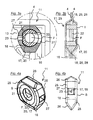
- the in FIG. 1 shown plate heater 1 has three heating plates 2, 3.
- the heating plates 2, 3 are welded from two half-shells 4 profiled by deep drawing steel sheet and to Schuffenan gleichö Maschinenen with Schuffenrohren 5.
- the heating means is supplied to the panel radiator 1 through the inlet 6 (at a lower, central distribution set), first passes through the front panel 2 and then the two rear heating plates 3 and is through the outlet 7 (at the lower distributor) derived from the panel radiator 1.
- the Schuffenan gleichö Maschinencken and the heating means are not shown.
- the heating plate 2 has a consisting only of a metallic, made of steel support area 8 spacers 9, on the top 10 of the panel radiator 1, the heating means by two identical, symmetrically arranged spacer 11 according to the invention derived, one of which in the FIGS. 3a and 3b in two detail sections through the heating plate 2 and in the FIGS. 4a to 4d and 5 is shown individually in different views in FIG.
- the heating medium flows substantially first upwards through a central heating channel 12 in the upper collecting channel 13, from this down through a plurality of heating channels 14 in the lower collecting channel 15 and finally up again by two peripheral heating channels 16 and through the Inventive spacer 11 in the rear heating plates.
- the spacer 11 has a support region 17 formed from a steel pipe section and an annular injection-molded polymer sealant 18 made of a silicone elastomer enclosing the support region 17.
- the support region 17 has a cylindrical jacket 19, two annular support shoulders 20 and in each case a bore 21.
- the jacket 19 has a substantially rectangular flow opening 22 for the heating means and this opposite a small vent hole 23.
- the polymer sealant 18 has a circular cylindrical inner surface 24 with a slight undersize relative to the jacket 19 of the support region 17.
- the polymer sealant 18 has a rectangular cross-section with edges 25 that are slightly outside and two oppositely directed, tapered sealing elements 26. Openings 27 are formed above the flow opening 22 and above the vent hole 23 of the support area 17 at the polymer sealant 18.
- the sealing elements 26 of the polymer sealant 18 two sections 28 of a passage cross-section 29 between the upper collecting channel 13 and the peripheral heating channel 16. This happens in that the spacer 11 together with the sealing means 18 blocks the cross section of the collecting channel 13 between the last and the penultimate heating channel 16.
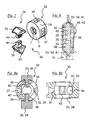
- first spacer 11 may in the FIGS. 6a to 6d and 7 in different views and in the FIGS. 8a and 8b shown in two sections further inventive spacer 30 as in FIG. 9 shown in the installed state in a heating plate 31 according to the invention of a plate heater according to the invention not shown used.
- the second spacer 30 has another support region 32 formed from a steel pipe section and a polymer sealant 34 made of a silicone elastomer injection-molded in two separate, wedge-shaped sealing elements 33.
- the support region 32 essentially has the dimensions of the support region 17 of the first spacer 11 according to the invention.
- the jacket 35 of the support portion 32 has two circular flow openings 36 for the heating means and this against a small vent hole 37.
- the support region 32 is provided with two opposite rectangular detent openings 38 with a matched cross-section for the sealing elements 33.
- the sealing elements 33 each have a slightly circular-cylindrical curved inner surface 39 and a holding portion in the form of a locking nipple 40 for connection to the support portion 32.
- a third embodiment of a spacer 43 is shown.
- the spacer 43 has a metallic support portion 44 and two therein sealing elements 45 outwardly upwardly and downwardly from a polymer sealant 46.
- a vent channel 47 is formed in the interior of the upper sealing element 45.
- the vent channel 47 extends tangentially to the annular shaped support portion 44th Der Venting channel 47 therefore provides no connection between the external environment of the spacer (in particular between the front region V or the rear region H) and the free space F of the spacer 43 arranged in the interior of the support region 44-in contrast to the second venting channel 48 described below ago.
- vent passage 47 exclusively performs a bypass function by connecting the front portion V and the rear portion H in the upper header.
- the inner circumferential surface of the vent channel 47 is formed by a metal pipe section 49, which embedded as a kind Support element acts.
- the second vent channel 48 of the spacer 43 has a conical shape, wherein the cross section of the outer periphery of the spacer 43 tapers to the inner space F out.
- the wall thickness of the support region 44 is increased, wherein the venting channel 48 is surrounded by a tapered collar 50 toward the inner free space F.
- Both the cross-sectional shape of the vent channel 48 itself and that of the collar 50 prevent passage of water from the internal clearance F of the spacer 43 into the rear part of the upper collecting channel during normal heating operation.
- FIG. 10b It can be seen that the flow through both of the venting channel 47 located in the polymer sealant 46 and the venting channel 48 located in the metallic support region 44 takes place respectively in the direction of the arrow 51, whereas the flow of the air from the front region V into the inner free space F of the spacer 43 in the direction of the arrow 52, that is, in the opposite direction.
Abstract
Description
Die Erfindung betrifft zunächst ein Verfahren zur Herstellung einer Heizplatte eines Plattenheizkörpers, wobei zwei Halbschalen, von denen mindestens eine profiliert ist, derart zu einer Heizplatte verbunden werden, dass zwischen den Halbschalen zwei parallel verlaufende Sammelkanäle und zwischen den Sammelkanälen Heizkanäle für ein Heizmittel ausgebildet werden, wobei im Bereich einer eine Halbschale durchdringenden Heizmittelanschlussöffnung in einem Sammelkanal ein Abstandhalter derart fixiert wird, dass gegenüberliegende Stützflächen eines Stützbereichs des Abstandhalters mit gegenüberliegenden Innenflächen der beiden Halbschalen in Kontakt kommen und ein Freibereich des Abstandhalters, der zumindest teilweise von dem Stützbereich umgeben wird, mit der Heizmittelanschlussöffnung korrespondiert.The invention relates firstly to a method for producing a heating plate of a panel radiator, wherein two half shells, of which at least one is profiled, are connected to form a heating plate such that between the half shells two parallel collecting channels and between the collecting channels heating channels are formed for a heating medium, wherein in the region of a half-shell penetrating Heizmittelanschlussöffnung in a collecting channel, a spacer is fixed so that opposite support surfaces of a support portion of the spacer come into contact with opposite inner surfaces of the two half-shells and a free area of the spacer which is at least partially surrounded by the support area with the Heizmittelanschlussöffnung corresponds.
Weiterhin betrifft die Erfindung einen Plattenheizkörper mit mindestens einer aus zwei Halbschalen, von denen mindestens eine profiliert ist, zusammengefügten Heizplatte, wobei zwischen den Halbschalen zwei parallel verlaufende Sammelkanäle und zwischen den Sammelkanälen Heizkanäle für ein Heizmittel ausgebildet sind, und mit mindestens einer, an einem der Sammelkanäle ausgebildeten Heizmittelanschlussöffnung der Heizplatte, und einem Abstandhalter, der im Bereich einer eine Halbschale durchdringenden Heizmittelanschlussöffnung in dem Sammelkanal derart fixiert ist, dass gegenüberliegende Stützflächen eines Stützbereichs des Abstandhalters mit gegenüberliegenden Innenflächen der beiden Halbschalen in Kontakt stehen und dass ein Freibereich des Abstandhalters, der zumindest teilweise von dem Stützbereich umgeben ist, mit der Heizmittelanschlussöffnung korrespondiert.Furthermore, the invention relates to a panel radiator with at least one of two half shells, of which at least one profiled, joined together heating plate, wherein between the half shells two parallel collecting channels and between the collecting channels heating channels are formed for a heating means, and with at least one, at one of Combustion channels formed Heizmittelanschlussöffnung the heating plate, and a spacer which is fixed in the region of a half shell penetrating Heizmittelanschlussöffnung in the collecting channel such that opposite support surfaces of a support portion of the spacer with opposite inner surfaces of the two half shells in contact and that an open area of the spacer, the at least partially surrounded by the support area, corresponding to the Heizmittelanschlussöffnung.
Schließlich betrifft die Erfindung einen Abstandhalter für eine aus zwei Halbschalen, von denen mindestens eine profiliert ist, zusammengesetzte Heizplatte eines Plattenheizkörpers, wobei zwischen den Halbschalen zwei parallel verlaufende Sammelkanäle und zwischen den Sammelkanälen Heizkanäle für ein Heizmittel ausgebildet sind, und wobei der Abstandhalter im Bereich der Heizmittelanschlussöffnung derart in dem Sammelkanal fixierbar ist, dass gegenüberliegende Stützflächen des Abstandhalters mit gegenüberliegenden Innenflächen der beiden Halbschalen in Kontakt stehen und ein Freibereich des Abstandhalters, der zumindest teilweise von dem Stützbereich umgeben ist, mit der Heizmittelanschlussöffnung korrespondiert.Finally, the invention relates to a spacer for one of two half-shells, of which at least one profiled composite heating plate of a plate heater, wherein between the half shells two parallel collecting channels and between the collecting channels heating channels are formed for a heating means, and wherein the spacer in the region Heizmittelanschlussöffnung is fixable in the collecting channel, that opposite support surfaces of the spacer with opposite inner surfaces of the two half-shells in contact and an open area of the spacer, which is at least partially surrounded by the support area, corresponding to the Heizmittelanschlussöffnung.
Ein Verfahren der vorstehend genannten Art, ein mit einem solchen Verfahren hergestellter Plattenheizkörper und ein Abstandhalter für einen solchen Plattenheizkörper sind beispielsweise aus der
Der ringförmige Abstandhalter wird innerhalb der Heizplatte in einen Durchlassquerschnitt von einem der Sammelkanäle zu mindestens einem der Heizkanäle eingefügt und verschließt diesen weitgehend, wobei zwischen dem äußeren Umfang des Abstandhalters und den Innenseiten der Halbschalen zwei in etwa dreiecksförmige Abschnitte des Durchlassquerschnitts offen bleiben. An Plattenheizkörpern, in denen - wie in der
Im Umfeld der Erfindung offenbart
Der Erfindung liegt die Aufgabe zugrunde, einen leckagefreien Heizmittelfluss zu ermöglichen, insbesondere eine gerichtete Strömung des Heizmittels durch bestimmte Heizkanäle oder Gruppen von Heizkanälen bzw. Sammelkanalabschnitte zu erlauben.The invention has for its object to enable a leak-free Heizmittelfluss, in particular to allow a directed flow of the heating means by certain heating channels or groups of heating channels or collecting duct sections.
Ausgehend von dem Verfahren der eingangs beschriebenen Art, wird die vorgenannte Aufgabe dadurch gelöst, dass mindestens ein Abstandhalter unter Verwendung eines Dichtmittels so in einem Sammelkanal fixiert wird, dass der Abstandhalter und das Dichtmittel gemeinsam den Sammelkanal fluiddicht versperren, wodurch eine Strömung des Heizmittels in Längsrichtung des Sammelkanals dort unterbunden wird.Based on the method of the type described above, the above object is achieved in that at least one spacer using a Sealant is fixed in a collecting channel, that the spacer and the sealant together block the collecting channel fluid-tight, whereby a flow of the heating medium in the longitudinal direction of the collecting channel is prevented there.
Die Erfindung unterscheidet sich somit dahingehend grundlegend vom vorgenannten Stand der Technik, dass von rein aus Stahlmaterial bestehenden Abstandhaltern abgerückt wird, zugunsten der zusätzlichen Verwendung eines Dichtmittels, um den Kanalquerschnitt nach Montage des Abstandhalters zusammen mit dem Dichtmittel zuverlässig zu verschließen. Die Schwierigkeit, eine hinreichend dichte Sperre in dem Sammelkanal allein mittels eines aus Stahl gefertigten Abstandhalters zu erreichen, liegt in den vergleichsweise großen Toleranzen im Bereich der Sammelkanalquerschnitte begründet, die wiederum aus den vergleichsweise großen Toleranzen bei der umformtechnischen Herstellung der beiden zusammenzufügenden Halbschalen resultiert. Während im Stützbereich die beiden Halbschalen im Wege des Anschweißens einer Verteilergarnitur (auch genannt "Anschlussteil") durch den beim Widerstandsschweißen aufgebrachten Pressdruck noch so aneinander geformt, insbesondere gebogen werden, dass eventuelle Spalten in ausreichendem Maß auch ohne Dichtmittel verschlossen werden, ist ein solcher Schließvorgang von Spalten im Bereich von Randabschnitten des Sammelkanal-Querschnitts, in denen häufig jeweils eine Dreieckform vorliegt, nicht möglich. Beim Verfahren nach dem Stand der Technik verbleiben daher, insbesondere in diesen an gegenüberliegenden Enden des Querschnitts liegenden, dreieckförmigen Zwickel-Querschnitten typischerweise freie Querschnitte, die unzulässig hohe Leckageströme verursachen und daher die mit Hilfe der Abstandhalter eigentlich bezweckte Strömungscharakteristik in einer Heizplatte empfindlich stören können. Hieraus resultieren im Stand der Technik erhebliche Leistungsverluste des Heizkörpers durch ungleichmäßige Erwärmung, da das Heizmittel an den Abstandhaltern vorbei einen Kurzschlussweg wählt.The invention thus differs fundamentally from the aforementioned prior art that is moved away from purely made of steel material spacers, in favor of the additional use of a sealant to reliably close the channel cross-section after assembly of the spacer together with the sealant. The difficulty of achieving a sufficiently tight barrier in the collecting channel solely by means of a spacer made of steel is due to the comparatively large tolerances in the region of the collecting channel cross sections, which in turn results from the comparatively large tolerances in the forming production of the two half-shells to be joined together. While in the support area, the two half-shells by means of welding a distributor set (also called "connector") by the pressure applied during resistance welding pressure even as molded together, in particular are bent that any gaps are sealed sufficiently without sealant, such a closing operation columns in the area of edge portions of the collection channel cross section, in which often each have a triangular shape, not possible. In the method according to the prior art, therefore, especially in these lying at opposite ends of the cross-section, triangular gusset cross-sections typically free cross-sections that cause inadmissibly high leakage currents and therefore can interfere with the actually intended by means of spacers flow characteristic in a hot plate sensitive. This results in the prior art, significant power losses of the radiator due to uneven heating, since the heating medium on the spacers over selects a Kurzschlussweg.
Grundsätzlich kann das Dichtmittel beim Herstellungsprozess der Heizplatte in die Sammelkanäle der Heizplatten (vor deren Zusammenfügen) eingebracht werden, woraufhin anschließend der Abstandhalter platziert wird oder aber das Dichtmittel wird vor dessen Einfügen in den Sammelkanal auf den Abstandhalter appliziert, so dass beide als Bauteil aus zwei kombinierten Werkstoffen gemeinsam gehandhabt und fixiert werden. Es ist aber auch möglich, ein solches werkstoffmäßiges Kombinationsbauteil in einem separaten Schritt vorzufabrizieren und sodann - wie die bisherigen rein aus Stahl bestehenden Abstandhalter auch - in dem Sammelkanal platzieren und beim Verbinden der Halbschalen zu fixieren.Basically, the sealant in the production process of the heating plate in the collecting ducts of the heating plates (before the joining) are introduced, after which the spacer is placed or the sealant is applied prior to its insertion into the collecting channel on the spacer, so that both as a component of two combined materials are handled and fixed together. But it is also possible to prefabricate such a material combination component in a separate step and then - like the previous existing purely steel spacers also - place in the collection channel and to fix when connecting the half shells.
Bei dem Dichtmittel kann es sich um einen Festkörper mit elastischen und/oder plastischen Materialeigenschaften handeln, aber auch um ein zähflüssiges, insbesondere pastöses Fluid, das durch eine zeitgesteuerte, temperaturgesteuerte oder strahlungsgesteuerte chemische und/oder physikalische Reaktion nach der Montage einen Zustand annimmt, in dem es Querschnittsbereiche, insbesondere Spaltbereiche zwischen dem Stützbereich des Abstandhalters und den inneren Wandungen des Sammelkanals, zuverlässig verschließt. Dabei muss das Dichtmittel in seinem "Endzustand" beständig gegen einen dauerhaften Angriff des Heizmittels sowie gegenüber erhöhten Temperaturen von ca. 80°C bis 100°C sein.The sealing means may be a solid having elastic and / or plastic material properties, but also a viscous, in particular pasty, fluid which assumes a state after a timed, temperature-controlled or radiation-controlled chemical and / or physical reaction it reliably closes cross-sectional areas, in particular gap areas, between the support area of the spacer and the inner walls of the collecting channel. In this case, the sealant in its "final state" must be resistant to a permanent attack of the heating medium and to elevated temperatures of about 80 ° C to 100 ° C.
Besonders vorteilhaft ist es, wenn das Dichtmittel ein Polymerdichtmittel ist. Überraschenderweise wird bei dem Vorgang des Anschweißens einer Verteilergarnitur im Bereich der Heizmittelanschlussöffnung sowie auch beim Verschweißen der zusammengefügten Halbschalen mittels Widerstandsschweißens aufgrund der kurzen Zeitspanne der Erhitzung nur wenig Wärme bis an die inneren Wandungen der Halbschalen im Bereich des Abstandhalters, d. h. insbesondere diesen außenumgebenden Dichtmittels, geleitet. Der Vorteil der polymeren Werkstoffe ("Kunststoffe") besteht in ihrer sehr leichten Formbarkeit und kosteneffizienten Herstellbarkeit, beispielsweise im Wege eines Spritzgieß- oder Extrusionsvorgangs.It is particularly advantageous if the sealant is a polymer sealant. Surprisingly, in the process of welding a distributor set in the area of the heating medium connection opening as well as during welding of the assembled half shells by means of resistance welding due to the short period of heating little heat up to the inner walls of the half shells in the region of the spacer, d. H. in particular this external environmental sealant, passed. The advantage of the polymeric materials ("plastics") is their very easy formability and cost-efficient manufacturability, for example by means of an injection molding or extrusion process.
Die erfindungsgemäße sehr gute Abdichtung im Bereich des in einem Sammelkanal eingesetzten Abstandhalters, ist insbesondere bei sogenannten seriellen Heizkörpern wichtig, bei denen die vordere Heizplatte zuerst und die hintere Heizplatte erst anschließend durchströmt werden soll, wozu gerichtete Strömungen zumindest innerhalb der vorderen Heizplatte nötig sind, um dort eine gleichmäßige Erwärmung zu erreichen.The very good seal according to the invention in the area of the spacer used in a collecting channel, especially in so-called serial radiators is important in which the front heating plate first and the rear heating plate to be flowed through only what directed flows are needed at least within the front heating plate to There to achieve a uniform heating.
Der Abstandhalter kann auch so eingesetzt werden, dass er zusammen mit dem Polymerdichtmittel einen Durchlassquerschnitt zwischen einem Sammelkanal und einem davon ausgehenden bzw. darin einbindenden Heizkanal abgedichtet verschließt. Das erfindungsgemäße Verfahren erlaubt es somit, einzelne Heizkanäle fluidtechnisch von dem zugeordneten Sammelkanal zu entkoppeln, um somit zum Beispiel einen einzelnen Heizkanal als "Steigkanal" für das Wärmeträgermedium zu verwenden, hingegen die übrigen Heizkanäle als "Sinkkanäle". Das Polymerdichtmittel verschließt dabei Spaltbereiche zwischen dem Stützbereich des Abstandhalters und den Halbschalen, d. h. den durch diese definierten Wandungen (Innenflächen) des Sammelkanals. Die Anpassungsfähigkeit des für die Dichtung verwendeten Polymer-Materials, das entweder plastisch oder elastisch sein kann oder eine Kombination der beiden vorgenannten Eigenschaften aufweisen kann, erlaubt es die Fertigungstoleranzen in Bezug auf den Querschnitt des Sammelkanals nicht unnötig stark zu beschränken, was insbesondere bei der Massenproduktion von Heizkörpern kaum wirtschaftlich darstellbar wäre.The spacer can also be used in such a way that, together with the polymer sealant, it closes off a passage cross-section between a collecting channel and a heating channel emanating therefrom or enclosing it. The invention Method thus allows fluid channels to decouple individual heating channels of the associated collection channel, thus, for example, to use a single heating channel as a "riser" for the heat transfer medium, however, the other heating channels as "sink channels". The polymer sealant closes gap regions between the support region of the spacer and the half-shells, ie the walls (inner surfaces) of the collecting channel defined by them. The adaptability of the polymer material used for the seal, which may be either plastic or elastic or may have a combination of the two aforementioned properties, does not allow to unnecessarily limit the manufacturing tolerances with respect to the cross-section of the collecting channel, especially in mass production of radiators would hardly represent economically.
Gemäß einer Weiterbildung der Erfindung ist vorgesehen, dass ein mit dem Polymerdichtmittel versehener Abstandhalter vor dem Verbinden der Halbschalen zumindest bereichsweise ein Übermaß in Bezug auf den Querschnitt des Sammelkanals besitzt und dass die Abdichtung durch das Verbinden der Halbschalen erfolgt, wobei das elastische oder plastische Polymerdichtmittel komprimiert oder ein viskoses eventuell seine Härte bzw. Zähigkeit vergrößerndes Polymerdichtmittel teilweise verdrängt wird.According to a development of the invention, it is provided that a spacer provided with the polymer sealant at least partially has an excess with respect to the cross section of the collecting channel before the half shells are connected and that the sealing takes place by connecting the half shells, wherein the elastic or plastic polymer sealant compresses or a viscous, possibly increasing its hardness or toughening polymer sealant is partially displaced.
Ein Polymerdichtmittel mit leichtem Übermaß gegenüber den zwischen Abstandhalter und Halbschalen noch verbleibenden offenen Abschnitten des Sammelkanals oder des Durchlassquerschnitts, das beim Zusammenfügen der Halbschalen gequetscht wird, schließt diese Abschnitte fluidtechnisch vollständig und vermeidet jeden Leckstrom des Heizmittels durch diese Abschnitte.A polymer sealant slightly oversized relative to the open between the spacers and shells remaining open portions of the collecting channel or the passage cross section, which is crushed when joining the half-shells, fluidly closes these sections completely and avoids any leakage of the heating medium through these sections.
Im Rahmen eines erfindungsgemäßen Verfahrens wird bevorzugt das Polymerdichtmittel mit dem Stützbereich zwischen die Halbschalen eingefügt und steht dort eventuell auch ohne Dichtmittel flächig dichtend in metallischem Kontakt. Der Abstandhalter kann dann als bauliche Einheit aus Stützbereich und Polymerdichtmittel vorgefertigt werden, um die Montage der Halbschalen zu vereinfachen und preisgünstiger zu gestalten. Alternativ kann zunächst ein Polymerdichtmittel an der Heizmittelanschlussöffnung auf die Halbschalen aufgebracht und anschließend der Stützbereich zwischen die Halbschalen gefügt werden. Ausgehend von den bekannten Plattenheizkörpern wird nach der Erfindung vorgeschlagen, dass mindestens ein Abstandhalter zusammen mit einem Dichtmittel so in einem Sammelkanal fixiert ist, dass der Abstandhalter und das Dichtmittel gemeinsam den Sammelkanal fluiddicht versperren, wodurch eine Strömung des Heizmittels in Längsrichtung des Sammelkanals dort unterbunden ist.In the context of a method according to the invention, the polymer sealant is preferably inserted with the support region between the half-shells and is there possibly even without sealant sealingly in metallic contact. The spacer can then be prefabricated as a structural unit of support and polymer sealant to simplify the assembly of the half shells and cheaper to design. Alternatively, first of all a polymer sealant can be applied to the half-shells at the heating medium connection opening, and then the support region can be joined between the half shells. Starting from the known plate radiators is proposed according to the invention that at least one spacer is fixed together with a sealant in a collecting channel, that the spacer and the sealant together block the collecting channel fluid-tight, whereby a flow of the heating medium in the longitudinal direction of the collecting channel is prevented there ,
Ausgehend von den bekannten Abstandhaltern wird nach der Erfindung vorgeschlagen, ein vorgeformtes Polymerdichtmittel vorzusehen, das nach dem Verbinden der Halbschalen den Sammelkanal zusammen mit dem Stützbereich fluiddicht verschließt. Ein solcher erfindungsgemäßer montagefertiger Abstandhalter ermöglicht die Ausführung eines erfindungsgemäßen Verfahrens und die Herstellung eines erfindungsgemäßen Plattenheizkörpers und zeichnet sich durch die oben genannten Vorteile aus. Alternativ kann ein pastöses, im Laufe des Herstellungsprozesses vorzugsweise sich verfestigendes Polymerdichtmittel zum Einsatz kommen.Starting from the known spacers is proposed according to the invention to provide a preformed polymer sealant, which closes the collecting channel fluid-tight together with the support area after connecting the half shells. Such a ready-to-mount spacer according to the invention makes it possible to carry out a method according to the invention and to produce a panel heater according to the invention and is distinguished by the abovementioned advantages. Alternatively, a pasty, preferably in the course of the manufacturing process solidifying polymer sealant can be used.
An einem erfindungsgemäßen Abstandhalter umschließt vorzugsweise das Polymerdichtmittel den Stützbereich an einem äußeren Umfang oder ist dort an den Stützbereich angeschlossen. Das Polymerdichtmittel besteht so aus einem einzelnen Bauteil oder mehreren Bauteilen und lässt sich daher besonders einfach auf oder an dem Stützbereich montieren, beispielsweise durch Klemmung oder Verklebung.On a spacer according to the invention, the polymer sealant preferably encloses the support region on an outer circumference or is connected there to the support region. The polymer sealant thus consists of a single component or a plurality of components and can therefore be particularly easily mounted on or on the support area, for example by clamping or gluing.
Alternativ weist das Polymerdichtmittel eine Mehrzahl von Dichtelementen auf und jedes der Dichtelemente verschließt jeweils einen von mehreren getrennten Abschnitten des Durchlassquerschnitts. Die Aufteilung des Polymerdichtmittels in mehrere Dichtelemente verringert den Materialaufwand für die Herstellung des Polymerdichtmittels und trägt so zu einer Verringerung der Kosten bei.Alternatively, the polymer sealant has a plurality of sealing elements and each of the sealing elements closes each one of a plurality of separate sections of the passage cross-section. The division of the polymer sealant into a plurality of sealing elements reduces the cost of materials for the production of the polymer sealant and thus contributes to a reduction in costs.
Besonders bevorzugt besteht an einem erfindungsgemäßen Abstandhalter das Polymerdichtmittel aus einem (Silikon-)elastomer. Silikonelastomere sind hoch temperatur- und wasserbeständig und gewährleisten eine hohe Gebrauchsdauer eines hiermit ausgestatteten erfindungsgemäßen Plattenheizkörpers. Alternativ kann als Material des Polymerdichtmittels ein Thermoplast zum Einsatz kommen und - durch entsprechende Führung des Schweißstroms - das Polymerdichtmittel in der Kontaktfläche zum Abstandhalter und zu den Halbschalen leicht aufgeschmolzen werden, so dass es beim Abkühlen mit diesen Oberflächen verklebt und eine dauerhafte Verbindung eingeht.Particularly preferably, the polymer sealant consists of a (silicone) elastomer on a spacer according to the invention. Silicone elastomers are highly resistant to temperature and water and ensure a long service life of a panel heater according to the invention equipped herewith. Alternatively, as a material of the polymer sealant, a thermoplastic can be used and - by appropriate management of the welding current - the polymer sealant in the contact surface to the spacer and to The half-shells are easily melted, so that it glued on cooling with these surfaces and enters into a permanent connection.
An einem erfindungsgemäßen Abstandhalter ist das Polymerdichtmittel vorteilhafter Weise mit dem Stützbereich formschlüssig verbunden ist. Das Polymerdichtmittel kann dann ohne zusätzliche Hilfsstoffe bei der Vormontage des Abstandhalters mit dem Stützbereich verbunden werden, z. B. mittels eines hinterschnittenen, widerhakenförmigen Fixierabschnitts. Alternativ kann das Polymerdichtmittel mit dem Stützbereich verklebt werden.On a spacer according to the invention, the polymer sealant is advantageously positively connected to the support region. The polymer sealant can then be connected without additional auxiliaries in the pre-assembly of the spacer with the support area, for. B. by means of an undercut, barb-shaped fixing section. Alternatively, the polymer sealant can be bonded to the support area.
Die Erfindung wird nachfolgend anhand von Ausführungsbeispielen erläutert. Es zeigen
- Fig. 1
- eine Seitenansicht eines erfindungsgemäßen Plattenheizkörpers,
- Fig. 2
- einen Schnitt einer ersten erfindungsgemäßen Heizplatte,
- Fig. 3a und b
- zwei Details des Schnittes der erfindungsgemäßen Heizplatte,
- Fig. 4a bis d
- vier Ansichten eines ersten erfindungsgemäßen Abstandhalters
- Fig. 5
- eine Explosionsdarstellung des ersten Abstandhalters,
- Fig. 6a bis d
- vier Ansichten eines zweiten erfindungsgemäßen Abstandhalters,
- Fig. 7
- eine Explosionsdarstellung des zweiten Abstandhalters,
- Fig. 8a und b
- zwei Schnitte des zweiten Abstandhalters und
- Fig. 9
- ein Detail eines Schnitts einer zweiten erfindungsgemäßen Heizplatte.
- Fig. 10a
- eine perspektivische Ansicht eines dritten erfindungsgemäßen Abstandhal- ters und
- Fig. 10b
- einen Schnitt durch den dritten Abstandhalter.
- Fig. 1
- a side view of a panel heater according to the invention,
- Fig. 2
- a section of a first heating plate according to the invention,
- Fig. 3a and b
- two details of the section of the heating plate according to the invention,
- Fig. 4a to d
- four views of a first spacer according to the invention
- Fig. 5
- an exploded view of the first spacer,
- Fig. 6a to d
- four views of a second spacer according to the invention,
- Fig. 7
- an exploded view of the second spacer,
- Fig. 8a and b
- two sections of the second spacer and
- Fig. 9
- a detail of a section of a second heating plate according to the invention.
- Fig. 10a
- a perspective view of a third spacer according to the invention and
- Fig. 10b
- a section through the third spacer.
Der in
Die in
Der erfindungsgemäße Abstandhalter 11 weist einen aus einem Stahlrohrabschnitt umgeformten Stützbereich 17 auf und ein den Stützbereich 17 umschließendes, ringförmig spritzgegossenes Polymerdichtmittel 18 aus einem Silikonelastomer.The
Der Stützbereich 17 weist einen zylinderförmigen Mantel 19, zwei kreisringförmige Stützschultern 20 und in diesen jeweils eine Bohrung 21 auf. Der Mantel 19 weist eine im Wesentlichen rechteckige Durchflussöffnung 22 für das Heizmittel und dieser gegenüber eine kleine Entlüftungsbohrung 23 auf.The
Das Polymerdichtmittel 18 weist eine kreiszylindrische Innenfläche 24 mit einem leichten Untermaß gegenüber dem Mantel 19 des Stützbereichs 17 auf. Das Polymerdichtmittel 18 weist einen rechteckigen Querschnitt mit außen leicht gefassten Kanten 25 und zwei einander gegenüber liegenden, spitz zulaufenden Dichtelementen 26 auf. An dem Polymerdichtmittel 18 sind Durchbrüche 27 über der Durchflussöffnung 22 und über der Entlüftungsbohrung 23 des Stützbereichs 17 ausgebildet. In dem in den
Anstelle des ersten Abstandhalters 11 kann der in den
Der zweite Abstandhalter 30 weist einen anderen, aus einem Stahlrohrabschnitt umgeformten Stützbereich 32 auf und ein in zwei getrennten, keilförmigen Dichtelementen 33 spritzgegossenes Polymerdichtmittel 34 aus einem Silikonelastomer.The
Der Stützbereich 32 weist im Wesentlichen die Maße des Stützbereiches 17 des ersten erfindungsgemäßen Abstandhalters 11 auf. Der Mantel 35 des Stützbereichs 32 weist zwei kreisförmige Durchflussöffnungen 36 für das Heizmittel und dieser gegenüber eine kleine Lüftungsbohrung 37 auf. Außerdem ist der Stützbereich 32 mit zwei gegenüber liegenden rechteckigen Rastöffnungen 38 mit einem angepassten Querschnitt für die Dichtelemente 33 versehen.The
Die Dichtelemente 33 weisen jeweils eine leicht kreiszylindrisch gekrümmte Innenfläche 39 und einen Halteabschnitt in Form eines Rastnippels 40 zum Verbinden mit dem Stützbereich 32 auf. In dem in
In den
Der zweite Entlüftungskanal 48 des Abstandhalters 43 besitzt eine kegelförmige Gestalt, wobei sich der Querschnitt von der äußeren Umgebung des Abstandhalters 43 auf den inneren Freiraum F hin verjüngt. Im Bereich des Entlüftungskanals 48 ist die Wandstärke des Stützbereichs 44 vergrößert, wobei der Entlüftungskanal 48 zum inneren Freiraum F hin von einem spitz zulaufenden Kragen 50 umgeben ist. Sowohl die Querschnittsgestalt des Entlüftungskanals 48 selbst als auch die des Kragens 50 verhindern während des normalen Heizbetriebs einen Durchtritt von Wasser aus dem inneren Freiraum F des Abstandhalters 43 in den hinteren Teil des oberen Sammelkanals.The
Aus
In den Figuren sind
- 1
- Plattenheizkörper
- 2
- Heizplatte
- 3
- Heizplatte
- 4
- Halbschale
- 5
- Heizmittelrohr
- 6
- Zulauf
- 7
- Ablauf
- 8
- Stützbereich
- 9
- Abstandhalter
- 10
- Oberseite
- 11
- Abstandhalter
- 12
- Heizkanal
- 13
- Sammelkanal
- 14
- Heizkanal
- 15
- Sammelkanal
- 16
- Heizkanal
- 17
- Stützbereich
- 18
- Polymerdichtmittel
- 19
- Mantel
- 20
- Stützschulter
- 21
- Bohrung
- 22
- Durchflussöffnung
- 23
- Entlüftungsbohrung
- 24
- Innenfläche
- 25
- Kante
- 26
- Dichtelement
- 27
- Durchbruch
- 28
- Abschnitt
- 29
- Durchlassquerschnitt
- 30
- Abstandhalter
- 31
- Heizplatte
- 32
- Stützbereich
- 33
- Dichtelement
- 34
- Polymerdichtmittel
- 35
- Mantel
- 36
- Durchflussöffnung
- 37
- Entlüftungsbohrung
- 38
- Rastöffnungen
- 39
- Innenfläche
- 40
- Rastnippel
- 41
- Abschnitt
- 42
- Durchlassquerschnitt
- 43
- Abstandhalter
- 44
- Stützbereich
- 45
- Dichtelement
- 46
- Polymerdichtmittel
- 47
- Entlüftungskanal
- 48
- Entlüftungskanal
- 49
- Rohrstück
- 50
- Kragen
- 51
- Pfeil
- 52
- Pfeil
- S
- Stützfläche
- I
- Innenfläche
- F
- Freiraum
- 1
- panel radiators
- 2
- heating plate
- 3
- heating plate
- 4
- half shell
- 5
- Heizmittelrohr
- 6
- Intake
- 7
- procedure
- 8th
- support area
- 9
- spacer
- 10
- top
- 11
- spacer
- 12
- heating duct
- 13
- collecting duct
- 14
- heating duct
- 15
- collecting duct
- 16
- heating duct
- 17
- support area
- 18
- Polymer sealant
- 19
- coat
- 20
- supporting shoulder
- 21
- drilling
- 22
- Flow opening
- 23
- vent hole
- 24
- palm
- 25
- edge
- 26
- sealing element
- 27
- breakthrough
- 28
- section
- 29
- Passage section
- 30
- spacer
- 31
- heating plate
- 32
- support area
- 33
- sealing element
- 34
- Polymer sealant
- 35
- coat
- 36
- Flow opening
- 37
- vent hole
- 38
- latching openings
- 39
- palm
- 40
- Rest nipple
- 41
- section
- 42
- Passage section
- 43
- spacer
- 44
- support area
- 45
- sealing element
- 46
- Polymer sealant
- 47
- vent channel
- 48
- vent channel
- 49
- pipe section
- 50
- collar
- 51
- arrow
- 52
- arrow
- S
- support surface
- I
- palm
- F
- free space
Claims (13)
Priority Applications (1)
| Application Number | Priority Date | Filing Date | Title |
|---|---|---|---|
| PL10163058T PL2256449T3 (en) | 2009-05-18 | 2010-05-18 | Method for producing a radiator plate, plate radiator body and distancer |
Applications Claiming Priority (1)
| Application Number | Priority Date | Filing Date | Title |
|---|---|---|---|
| DE102009003182A DE102009003182A1 (en) | 2009-05-18 | 2009-05-18 | Method for producing a heating plate, plate radiator and spacers |
Publications (3)
| Publication Number | Publication Date |
|---|---|
| EP2256449A2 true EP2256449A2 (en) | 2010-12-01 |
| EP2256449A3 EP2256449A3 (en) | 2011-03-23 |
| EP2256449B1 EP2256449B1 (en) | 2012-06-20 |
Family
ID=42646449
Family Applications (1)
| Application Number | Title | Priority Date | Filing Date |
|---|---|---|---|
| EP10163058A Active EP2256449B1 (en) | 2009-05-18 | 2010-05-18 | Method for producing a radiator plate, plate radiator body and distancer |
Country Status (3)
| Country | Link |
|---|---|
| EP (1) | EP2256449B1 (en) |
| DE (1) | DE102009003182A1 (en) |
| PL (1) | PL2256449T3 (en) |
Cited By (1)
| Publication number | Priority date | Publication date | Assignee | Title |
|---|---|---|---|---|
| DE102014111739A1 (en) | 2014-08-18 | 2016-02-18 | Caradon Stelrad B.V. | Spacer and method for its production |
Families Citing this family (2)
| Publication number | Priority date | Publication date | Assignee | Title |
|---|---|---|---|---|
| DE102011050135A1 (en) | 2011-05-05 | 2012-11-08 | Caradon Stelrad B.V. | panel radiators |
| DE202016007439U1 (en) | 2015-12-07 | 2017-03-27 | Hans Berg Gmbh & Co. Kg | Spacer element for placement in a radiator plate and radiator with at least one such spacer element |
Citations (2)
| Publication number | Priority date | Publication date | Assignee | Title |
|---|---|---|---|---|
| DE7247319U (en) | 1973-04-12 | Schaefer H Ag | Plate radiator, consisting of two profiled steel sheets | |
| AT411493B (en) | 1999-10-15 | 2004-01-26 | Vogel & Noot Waermetechnik Ag | PANEL RADIATORS AND SUPPORT FOR IT |
Family Cites Families (7)
| Publication number | Priority date | Publication date | Assignee | Title |
|---|---|---|---|---|
| FI53751C (en) * | 1973-06-21 | 1978-07-10 | Rettig Strengberg Ab Oy | RADIATOR MED INLOPPS- RESP UTLOPPSANSLUTNINGAR FOER ETT VAERMEMEDIUM |
| DE3113208C2 (en) * | 1981-04-02 | 1990-07-12 | Harry 6472 Altenstadt König | Method for connecting one, two or three parallel plate heating elements by pressure welding |
| DE3440272A1 (en) * | 1984-11-03 | 1986-05-15 | Hans Berg Verwaltungsgesellschaft mbH und Co KG, 5226 Reichshof | Process for the production of a supporting part for flat radiators |
| SE462763B (en) * | 1989-04-28 | 1990-08-27 | Torell Ab | PLATFORM HEAT EXCHANGE / COOLER AND WERE MANUFACTURED TO MANUFACTURE THIS |
| JP3359946B2 (en) * | 1993-03-04 | 2002-12-24 | 東京ラヂエーター製造株式会社 | Stacked heat exchanger |
| DE10223790B4 (en) * | 2002-05-29 | 2005-08-18 | Bbt Thermotechnik Gmbh | panel radiators |
| DE102004011634B3 (en) * | 2004-03-10 | 2005-09-15 | Bbt Thermotechnik Gmbh | Push-fit hot water feed supply standard connector fitting for industrial heating plate system |
-
2009
- 2009-05-18 DE DE102009003182A patent/DE102009003182A1/en not_active Withdrawn
-
2010
- 2010-05-18 PL PL10163058T patent/PL2256449T3/en unknown
- 2010-05-18 EP EP10163058A patent/EP2256449B1/en active Active
Patent Citations (2)
| Publication number | Priority date | Publication date | Assignee | Title |
|---|---|---|---|---|
| DE7247319U (en) | 1973-04-12 | Schaefer H Ag | Plate radiator, consisting of two profiled steel sheets | |
| AT411493B (en) | 1999-10-15 | 2004-01-26 | Vogel & Noot Waermetechnik Ag | PANEL RADIATORS AND SUPPORT FOR IT |
Cited By (2)
| Publication number | Priority date | Publication date | Assignee | Title |
|---|---|---|---|---|
| DE102014111739A1 (en) | 2014-08-18 | 2016-02-18 | Caradon Stelrad B.V. | Spacer and method for its production |
| EP2995872A1 (en) | 2014-08-18 | 2016-03-16 | Caradon Stelrad B.V. | Spacer and method for its manufacture |
Also Published As
| Publication number | Publication date |
|---|---|
| PL2256449T3 (en) | 2012-12-31 |
| EP2256449B1 (en) | 2012-06-20 |
| EP2256449A3 (en) | 2011-03-23 |
| DE102009003182A1 (en) | 2010-11-25 |
Similar Documents
| Publication | Publication Date | Title |
|---|---|---|
| EP2494179B1 (en) | Exhaust gas heat exchanger | |
| DE102007040848B4 (en) | Process for the preparation of a heat exchanger, and a heat exchanger produced by the process | |
| DE102006051000A1 (en) | Exhaust gas heat exchanger for internal combustion engine of motor vehicle, has sealing unit provided in sectional contact with one of mediums, and turbulence generator provided within housing, where medium is passed within generator | |
| EP2205922A1 (en) | Heat exchanger, particularly an oil cooler | |
| DE102015202851A1 (en) | Fluid conduit means | |
| DE202011002197U1 (en) | heat exchangers | |
| EP2508832A1 (en) | Plastic plate heat exchanger | |
| DE102007043992B4 (en) | Charge air module for an internal combustion engine | |
| DE102017109708A1 (en) | Cooling arrangement, fluid collector for a cooling arrangement and method for producing a fluid collector | |
| EP2256449B1 (en) | Method for producing a radiator plate, plate radiator body and distancer | |
| DE202008008437U1 (en) | Plastic-coated plate heat exchanger | |
| DE202009011641U1 (en) | Plastic pipe | |
| EP2278235A2 (en) | Connection component of a heating element of a heater and flat heater | |
| EP2611595B1 (en) | Air intake tube | |
| DE102008039403A1 (en) | heater | |
| EP1669691B1 (en) | Multi-row radiator, in particular plate radiator | |
| EP2256426B1 (en) | Plate radiator | |
| EP2703611B1 (en) | Fluid heater and method for producing a fluid heater | |
| DE102016003521A1 (en) | Filter element of a filter, filter and fluid system with at least one filter element | |
| DE19653440A1 (en) | Heating device, preferably made of plastic | |
| EP1731850A2 (en) | Flangeless plastic boiler | |
| EP2821729B1 (en) | Heat exchange device and heating device | |
| EP3510835B1 (en) | Annular heating element | |
| DE102013100366A1 (en) | Double-walled exhaust gas volume and corresponding manufacturing process | |
| EP2161526A2 (en) | Method for manufacturing a plate heat exchanger and plate heat exchanger manufactured according to this method |
Legal Events
| Date | Code | Title | Description |
|---|---|---|---|
| PUAI | Public reference made under article 153(3) epc to a published international application that has entered the european phase |
Free format text: ORIGINAL CODE: 0009012 |
|
| AK | Designated contracting states |
Kind code of ref document: A2 Designated state(s): AL AT BE BG CH CY CZ DE DK EE ES FI FR GB GR HR HU IE IS IT LI LT LU LV MC MK MT NL NO PL PT RO SE SI SK SM TR |
|
| AX | Request for extension of the european patent |
Extension state: BA ME RS |
|
| PUAL | Search report despatched |
Free format text: ORIGINAL CODE: 0009013 |
|
| AK | Designated contracting states |
Kind code of ref document: A3 Designated state(s): AL AT BE BG CH CY CZ DE DK EE ES FI FR GB GR HR HU IE IS IT LI LT LU LV MC MK MT NL NO PL PT RO SE SI SK SM TR |
|
| AX | Request for extension of the european patent |
Extension state: BA ME RS |
|
| 17P | Request for examination filed |
Effective date: 20110916 |
|
| 17Q | First examination report despatched |
Effective date: 20111026 |
|
| GRAP | Despatch of communication of intention to grant a patent |
Free format text: ORIGINAL CODE: EPIDOSNIGR1 |
|
| GRAS | Grant fee paid |
Free format text: ORIGINAL CODE: EPIDOSNIGR3 |
|
| GRAA | (expected) grant |
Free format text: ORIGINAL CODE: 0009210 |
|
| AK | Designated contracting states |
Kind code of ref document: B1 Designated state(s): AL AT BE BG CH CY CZ DE DK EE ES FI FR GB GR HR HU IE IS IT LI LT LU LV MC MK MT NL NO PL PT RO SE SI SK SM TR |
|
| REG | Reference to a national code |
Ref country code: GB Ref legal event code: FG4D Free format text: NOT ENGLISH |
|
| REG | Reference to a national code |
Ref country code: CH Ref legal event code: EP |
|
| REG | Reference to a national code |
Ref country code: AT Ref legal event code: REF Ref document number: 563295 Country of ref document: AT Kind code of ref document: T Effective date: 20120715 |
|
| REG | Reference to a national code |
Ref country code: IE Ref legal event code: FG4D Free format text: LANGUAGE OF EP DOCUMENT: GERMAN |
|
| REG | Reference to a national code |
Ref country code: DE Ref legal event code: R096 Ref document number: 502010000899 Country of ref document: DE Effective date: 20120816 |
|
| REG | Reference to a national code |
Ref country code: NL Ref legal event code: T3 |
|
| PG25 | Lapsed in a contracting state [announced via postgrant information from national office to epo] |
Ref country code: FI Free format text: LAPSE BECAUSE OF FAILURE TO SUBMIT A TRANSLATION OF THE DESCRIPTION OR TO PAY THE FEE WITHIN THE PRESCRIBED TIME-LIMIT Effective date: 20120620 Ref country code: NO Free format text: LAPSE BECAUSE OF FAILURE TO SUBMIT A TRANSLATION OF THE DESCRIPTION OR TO PAY THE FEE WITHIN THE PRESCRIBED TIME-LIMIT Effective date: 20120920 Ref country code: LT Free format text: LAPSE BECAUSE OF FAILURE TO SUBMIT A TRANSLATION OF THE DESCRIPTION OR TO PAY THE FEE WITHIN THE PRESCRIBED TIME-LIMIT Effective date: 20120620 Ref country code: SE Free format text: LAPSE BECAUSE OF FAILURE TO SUBMIT A TRANSLATION OF THE DESCRIPTION OR TO PAY THE FEE WITHIN THE PRESCRIBED TIME-LIMIT Effective date: 20120620 |
|
| REG | Reference to a national code |
Ref country code: LT Ref legal event code: MG4D Effective date: 20120620 |
|
| PG25 | Lapsed in a contracting state [announced via postgrant information from national office to epo] |
Ref country code: LV Free format text: LAPSE BECAUSE OF FAILURE TO SUBMIT A TRANSLATION OF THE DESCRIPTION OR TO PAY THE FEE WITHIN THE PRESCRIBED TIME-LIMIT Effective date: 20120620 Ref country code: SI Free format text: LAPSE BECAUSE OF FAILURE TO SUBMIT A TRANSLATION OF THE DESCRIPTION OR TO PAY THE FEE WITHIN THE PRESCRIBED TIME-LIMIT Effective date: 20120620 Ref country code: HR Free format text: LAPSE BECAUSE OF FAILURE TO SUBMIT A TRANSLATION OF THE DESCRIPTION OR TO PAY THE FEE WITHIN THE PRESCRIBED TIME-LIMIT Effective date: 20120620 Ref country code: GR Free format text: LAPSE BECAUSE OF FAILURE TO SUBMIT A TRANSLATION OF THE DESCRIPTION OR TO PAY THE FEE WITHIN THE PRESCRIBED TIME-LIMIT Effective date: 20120921 |
|
| REG | Reference to a national code |
Ref country code: PL Ref legal event code: T3 |
|
| PG25 | Lapsed in a contracting state [announced via postgrant information from national office to epo] |
Ref country code: CY Free format text: LAPSE BECAUSE OF FAILURE TO SUBMIT A TRANSLATION OF THE DESCRIPTION OR TO PAY THE FEE WITHIN THE PRESCRIBED TIME-LIMIT Effective date: 20120620 Ref country code: IS Free format text: LAPSE BECAUSE OF FAILURE TO SUBMIT A TRANSLATION OF THE DESCRIPTION OR TO PAY THE FEE WITHIN THE PRESCRIBED TIME-LIMIT Effective date: 20121020 Ref country code: SK Free format text: LAPSE BECAUSE OF FAILURE TO SUBMIT A TRANSLATION OF THE DESCRIPTION OR TO PAY THE FEE WITHIN THE PRESCRIBED TIME-LIMIT Effective date: 20120620 Ref country code: RO Free format text: LAPSE BECAUSE OF FAILURE TO SUBMIT A TRANSLATION OF THE DESCRIPTION OR TO PAY THE FEE WITHIN THE PRESCRIBED TIME-LIMIT Effective date: 20120620 Ref country code: EE Free format text: LAPSE BECAUSE OF FAILURE TO SUBMIT A TRANSLATION OF THE DESCRIPTION OR TO PAY THE FEE WITHIN THE PRESCRIBED TIME-LIMIT Effective date: 20120620 |
|
| PG25 | Lapsed in a contracting state [announced via postgrant information from national office to epo] |
Ref country code: IT Free format text: LAPSE BECAUSE OF FAILURE TO SUBMIT A TRANSLATION OF THE DESCRIPTION OR TO PAY THE FEE WITHIN THE PRESCRIBED TIME-LIMIT Effective date: 20120620 Ref country code: PT Free format text: LAPSE BECAUSE OF FAILURE TO SUBMIT A TRANSLATION OF THE DESCRIPTION OR TO PAY THE FEE WITHIN THE PRESCRIBED TIME-LIMIT Effective date: 20121022 |
|
| PLBE | No opposition filed within time limit |
Free format text: ORIGINAL CODE: 0009261 |
|
| STAA | Information on the status of an ep patent application or granted ep patent |
Free format text: STATUS: NO OPPOSITION FILED WITHIN TIME LIMIT |
|
| PG25 | Lapsed in a contracting state [announced via postgrant information from national office to epo] |
Ref country code: DK Free format text: LAPSE BECAUSE OF FAILURE TO SUBMIT A TRANSLATION OF THE DESCRIPTION OR TO PAY THE FEE WITHIN THE PRESCRIBED TIME-LIMIT Effective date: 20120620 Ref country code: ES Free format text: LAPSE BECAUSE OF FAILURE TO SUBMIT A TRANSLATION OF THE DESCRIPTION OR TO PAY THE FEE WITHIN THE PRESCRIBED TIME-LIMIT Effective date: 20121001 |
|
| 26N | No opposition filed |
Effective date: 20130321 |
|
| REG | Reference to a national code |
Ref country code: DE Ref legal event code: R097 Ref document number: 502010000899 Country of ref document: DE Effective date: 20130321 |
|
| PG25 | Lapsed in a contracting state [announced via postgrant information from national office to epo] |
Ref country code: BG Free format text: LAPSE BECAUSE OF FAILURE TO SUBMIT A TRANSLATION OF THE DESCRIPTION OR TO PAY THE FEE WITHIN THE PRESCRIBED TIME-LIMIT Effective date: 20120920 |
|
| PG25 | Lapsed in a contracting state [announced via postgrant information from national office to epo] |
Ref country code: MC Free format text: LAPSE BECAUSE OF FAILURE TO SUBMIT A TRANSLATION OF THE DESCRIPTION OR TO PAY THE FEE WITHIN THE PRESCRIBED TIME-LIMIT Effective date: 20120620 |
|
| REG | Reference to a national code |
Ref country code: IE Ref legal event code: MM4A |
|
| PG25 | Lapsed in a contracting state [announced via postgrant information from national office to epo] |
Ref country code: IE Free format text: LAPSE BECAUSE OF NON-PAYMENT OF DUE FEES Effective date: 20130518 |
|
| REG | Reference to a national code |
Ref country code: CH Ref legal event code: PL |
|
| PG25 | Lapsed in a contracting state [announced via postgrant information from national office to epo] |
Ref country code: CH Free format text: LAPSE BECAUSE OF NON-PAYMENT OF DUE FEES Effective date: 20140531 Ref country code: LI Free format text: LAPSE BECAUSE OF NON-PAYMENT OF DUE FEES Effective date: 20140531 |
|
| PG25 | Lapsed in a contracting state [announced via postgrant information from national office to epo] |
Ref country code: MT Free format text: LAPSE BECAUSE OF FAILURE TO SUBMIT A TRANSLATION OF THE DESCRIPTION OR TO PAY THE FEE WITHIN THE PRESCRIBED TIME-LIMIT Effective date: 20120620 |
|
| PG25 | Lapsed in a contracting state [announced via postgrant information from national office to epo] |
Ref country code: SM Free format text: LAPSE BECAUSE OF FAILURE TO SUBMIT A TRANSLATION OF THE DESCRIPTION OR TO PAY THE FEE WITHIN THE PRESCRIBED TIME-LIMIT Effective date: 20120620 |
|
| PG25 | Lapsed in a contracting state [announced via postgrant information from national office to epo] |
Ref country code: HU Free format text: LAPSE BECAUSE OF FAILURE TO SUBMIT A TRANSLATION OF THE DESCRIPTION OR TO PAY THE FEE WITHIN THE PRESCRIBED TIME-LIMIT; INVALID AB INITIO Effective date: 20100518 Ref country code: MK Free format text: LAPSE BECAUSE OF FAILURE TO SUBMIT A TRANSLATION OF THE DESCRIPTION OR TO PAY THE FEE WITHIN THE PRESCRIBED TIME-LIMIT Effective date: 20120620 Ref country code: LU Free format text: LAPSE BECAUSE OF NON-PAYMENT OF DUE FEES Effective date: 20130518 |
|
| REG | Reference to a national code |
Ref country code: FR Ref legal event code: PLFP Year of fee payment: 7 |
|
| REG | Reference to a national code |
Ref country code: FR Ref legal event code: PLFP Year of fee payment: 8 |
|
| REG | Reference to a national code |
Ref country code: FR Ref legal event code: PLFP Year of fee payment: 9 |
|
| PG25 | Lapsed in a contracting state [announced via postgrant information from national office to epo] |
Ref country code: AL Free format text: LAPSE BECAUSE OF FAILURE TO SUBMIT A TRANSLATION OF THE DESCRIPTION OR TO PAY THE FEE WITHIN THE PRESCRIBED TIME-LIMIT Effective date: 20120620 |
|
| REG | Reference to a national code |
Ref country code: DE Ref legal event code: R082 Ref document number: 502010000899 Country of ref document: DE Representative=s name: BAUER WAGNER PELLENGAHR SROKA PATENT- & RECHTS, DE |
|
| P01 | Opt-out of the competence of the unified patent court (upc) registered |
Effective date: 20230525 |
|
| PGFP | Annual fee paid to national office [announced via postgrant information from national office to epo] |
Ref country code: NL Payment date: 20230525 Year of fee payment: 14 Ref country code: FR Payment date: 20230523 Year of fee payment: 14 Ref country code: DE Payment date: 20230531 Year of fee payment: 14 Ref country code: CZ Payment date: 20230516 Year of fee payment: 14 |
|
| PGFP | Annual fee paid to national office [announced via postgrant information from national office to epo] |
Ref country code: TR Payment date: 20230428 Year of fee payment: 14 Ref country code: PL Payment date: 20230428 Year of fee payment: 14 Ref country code: AT Payment date: 20230519 Year of fee payment: 14 |
|
| PGFP | Annual fee paid to national office [announced via postgrant information from national office to epo] |
Ref country code: BE Payment date: 20230525 Year of fee payment: 14 |
|
| PGFP | Annual fee paid to national office [announced via postgrant information from national office to epo] |
Ref country code: GB Payment date: 20230523 Year of fee payment: 14 |