EP2255959A2 - Verfahren zum Verankern von Spikes im Laufstreifen eines Fahrzeugluftreifens - Google Patents
Verfahren zum Verankern von Spikes im Laufstreifen eines Fahrzeugluftreifens Download PDFInfo
- Publication number
- EP2255959A2 EP2255959A2 EP09177433A EP09177433A EP2255959A2 EP 2255959 A2 EP2255959 A2 EP 2255959A2 EP 09177433 A EP09177433 A EP 09177433A EP 09177433 A EP09177433 A EP 09177433A EP 2255959 A2 EP2255959 A2 EP 2255959A2
- Authority
- EP
- European Patent Office
- Prior art keywords
- spikes
- adhesive system
- tread
- spike
- tire
- Prior art date
- Legal status (The legal status is an assumption and is not a legal conclusion. Google has not performed a legal analysis and makes no representation as to the accuracy of the status listed.)
- Granted
Links
- 238000000034 method Methods 0.000 title claims abstract description 28
- 238000004873 anchoring Methods 0.000 title claims description 3
- 239000000853 adhesive Substances 0.000 claims abstract description 57
- 230000001070 adhesive effect Effects 0.000 claims abstract description 57
- 239000011248 coating agent Substances 0.000 claims abstract description 14
- 238000000576 coating method Methods 0.000 claims abstract description 14
- 239000000463 material Substances 0.000 claims abstract description 10
- 230000003213 activating effect Effects 0.000 claims abstract description 6
- XLYOFNOQVPJJNP-UHFFFAOYSA-N water Substances O XLYOFNOQVPJJNP-UHFFFAOYSA-N 0.000 claims abstract description 4
- 230000006698 induction Effects 0.000 claims description 34
- 238000010438 heat treatment Methods 0.000 claims description 31
- 238000007598 dipping method Methods 0.000 claims description 10
- 239000007788 liquid Substances 0.000 claims description 9
- 238000001035 drying Methods 0.000 claims description 7
- 238000004073 vulcanization Methods 0.000 claims description 5
- 230000033001 locomotion Effects 0.000 claims description 4
- 239000013590 bulk material Substances 0.000 claims description 3
- 238000007654 immersion Methods 0.000 claims description 3
- 238000005507 spraying Methods 0.000 claims description 3
- 239000004020 conductor Substances 0.000 claims description 2
- 229910052751 metal Inorganic materials 0.000 description 7
- 239000002184 metal Substances 0.000 description 7
- 238000003491 array Methods 0.000 description 6
- 230000004913 activation Effects 0.000 description 3
- 239000000919 ceramic Substances 0.000 description 2
- 239000003795 chemical substances by application Substances 0.000 description 2
- 230000006835 compression Effects 0.000 description 2
- 238000007906 compression Methods 0.000 description 2
- 230000009189 diving Effects 0.000 description 2
- 239000010410 layer Substances 0.000 description 2
- 239000004033 plastic Substances 0.000 description 2
- 239000000126 substance Substances 0.000 description 2
- 229910000831 Steel Inorganic materials 0.000 description 1
- 229910045601 alloy Inorganic materials 0.000 description 1
- 239000000956 alloy Substances 0.000 description 1
- 229910052782 aluminium Inorganic materials 0.000 description 1
- XAGFODPZIPBFFR-UHFFFAOYSA-N aluminium Chemical compound [Al] XAGFODPZIPBFFR-UHFFFAOYSA-N 0.000 description 1
- 230000005540 biological transmission Effects 0.000 description 1
- 238000004140 cleaning Methods 0.000 description 1
- 150000001875 compounds Chemical class 0.000 description 1
- 238000003618 dip coating Methods 0.000 description 1
- 230000000694 effects Effects 0.000 description 1
- 230000005674 electromagnetic induction Effects 0.000 description 1
- 238000009776 industrial production Methods 0.000 description 1
- 238000003780 insertion Methods 0.000 description 1
- 230000037431 insertion Effects 0.000 description 1
- 238000007689 inspection Methods 0.000 description 1
- 230000010354 integration Effects 0.000 description 1
- 238000004519 manufacturing process Methods 0.000 description 1
- 238000002844 melting Methods 0.000 description 1
- 230000008018 melting Effects 0.000 description 1
- 229910001092 metal group alloy Inorganic materials 0.000 description 1
- 238000000465 moulding Methods 0.000 description 1
- 230000003071 parasitic effect Effects 0.000 description 1
- 239000004810 polytetrafluoroethylene Substances 0.000 description 1
- 229920001343 polytetrafluoroethylene Polymers 0.000 description 1
- 230000005855 radiation Effects 0.000 description 1
- 238000005096 rolling process Methods 0.000 description 1
- 150000003839 salts Chemical class 0.000 description 1
- 239000002356 single layer Substances 0.000 description 1
- 239000002904 solvent Substances 0.000 description 1
- 239000010959 steel Substances 0.000 description 1
- 238000002604 ultrasonography Methods 0.000 description 1
Images





Classifications
-
- B—PERFORMING OPERATIONS; TRANSPORTING
- B29—WORKING OF PLASTICS; WORKING OF SUBSTANCES IN A PLASTIC STATE IN GENERAL
- B29D—PRODUCING PARTICULAR ARTICLES FROM PLASTICS OR FROM SUBSTANCES IN A PLASTIC STATE
- B29D30/00—Producing pneumatic or solid tyres or parts thereof
- B29D30/06—Pneumatic tyres or parts thereof (e.g. produced by casting, moulding, compression moulding, injection moulding, centrifugal casting)
- B29D30/52—Unvulcanised treads, e.g. on used tyres; Retreading
- B29D30/66—Moulding treads on to tyre casings, e.g. non-skid treads with spikes
-
- B—PERFORMING OPERATIONS; TRANSPORTING
- B60—VEHICLES IN GENERAL
- B60C—VEHICLE TYRES; TYRE INFLATION; TYRE CHANGING; CONNECTING VALVES TO INFLATABLE ELASTIC BODIES IN GENERAL; DEVICES OR ARRANGEMENTS RELATED TO TYRES
- B60C11/00—Tyre tread bands; Tread patterns; Anti-skid inserts
- B60C11/14—Anti-skid inserts, e.g. vulcanised into the tread band
- B60C11/16—Anti-skid inserts, e.g. vulcanised into the tread band of plug form, e.g. made from metal, textile
-
- B—PERFORMING OPERATIONS; TRANSPORTING
- B05—SPRAYING OR ATOMISING IN GENERAL; APPLYING FLUENT MATERIALS TO SURFACES, IN GENERAL
- B05C—APPARATUS FOR APPLYING FLUENT MATERIALS TO SURFACES, IN GENERAL
- B05C3/00—Apparatus in which the work is brought into contact with a bulk quantity of liquid or other fluent material
- B05C3/02—Apparatus in which the work is brought into contact with a bulk quantity of liquid or other fluent material the work being immersed in the liquid or other fluent material
- B05C3/09—Apparatus in which the work is brought into contact with a bulk quantity of liquid or other fluent material the work being immersed in the liquid or other fluent material for treating separate articles
- B05C3/10—Apparatus in which the work is brought into contact with a bulk quantity of liquid or other fluent material the work being immersed in the liquid or other fluent material for treating separate articles the articles being moved through the liquid or other fluent material
-
- B—PERFORMING OPERATIONS; TRANSPORTING
- B29—WORKING OF PLASTICS; WORKING OF SUBSTANCES IN A PLASTIC STATE IN GENERAL
- B29C—SHAPING OR JOINING OF PLASTICS; SHAPING OF MATERIAL IN A PLASTIC STATE, NOT OTHERWISE PROVIDED FOR; AFTER-TREATMENT OF THE SHAPED PRODUCTS, e.g. REPAIRING
- B29C35/00—Heating, cooling or curing, e.g. crosslinking or vulcanising; Apparatus therefor
- B29C35/02—Heating or curing, e.g. crosslinking or vulcanizing during moulding, e.g. in a mould
- B29C35/08—Heating or curing, e.g. crosslinking or vulcanizing during moulding, e.g. in a mould by wave energy or particle radiation
- B29C35/0805—Heating or curing, e.g. crosslinking or vulcanizing during moulding, e.g. in a mould by wave energy or particle radiation using electromagnetic radiation
- B29C2035/0811—Heating or curing, e.g. crosslinking or vulcanizing during moulding, e.g. in a mould by wave energy or particle radiation using electromagnetic radiation using induction
-
- B—PERFORMING OPERATIONS; TRANSPORTING
- B29—WORKING OF PLASTICS; WORKING OF SUBSTANCES IN A PLASTIC STATE IN GENERAL
- B29D—PRODUCING PARTICULAR ARTICLES FROM PLASTICS OR FROM SUBSTANCES IN A PLASTIC STATE
- B29D30/00—Producing pneumatic or solid tyres or parts thereof
- B29D30/06—Pneumatic tyres or parts thereof (e.g. produced by casting, moulding, compression moulding, injection moulding, centrifugal casting)
- B29D30/52—Unvulcanised treads, e.g. on used tyres; Retreading
- B29D30/66—Moulding treads on to tyre casings, e.g. non-skid treads with spikes
- B29D2030/662—Treads with antiskid properties, i.e. with spikes
Definitions
- the invention relates to a method for anchoring spikes in a tread of a pneumatic vehicle tire, wherein the spikes are introduced into sprocket holes in the tread, which have been formed in the vulcanization of the tire in a hot press.
- the invention further relates to devices for coating spikes with an adhesive system, devices for activating the adhesive system and a spiked pneumatic vehicle tire.
- Spikes are usually held by a combination of positive engagement and clamping in the spike holes of the tread of pneumatic vehicle tires and have a spike body made of metal, in particular steel, or plastic, in which the over the tread surface protruding spike pin, which consists in particular of a hard metal, is held.
- Spike holes and spiked bodies are geometrically designed so that the compression of the tread rubber largely prevents the spikes from undesirably leaving the tread.
- the spikes in the vulcanizing mold of the tire are inserted at specially provided seats, the green tire is introduced into the mold and vulcanised after closing the mold of the green tires.
- the spikes are held in the mold by magnets such that the generated magnetic force is able to fix each spike in its predetermined position during the molding of the tire, especially during trapping of the spikes in the tread material.
- the force exerted by the magnets in the mold on the spikes may cause the vulcanized tire to be pulled out of the mold do not hinder.
- the spikes are either treated with an adhesive system or provided with a layer of an adhesive system, which increases the holding power of the spikes in the tread.
- this known method is technically very complicated and expensive.
- the invention is therefore based on the object to provide a method which allows a largely stress-resistant integration of spikes in the tread of already vulcanized tires, so that the risk of spike loss is reduced under high loads. Moreover, the invention is intended to enable the rubber compound (s) underlying the tread to be designed in such a way that the winter properties of the tread can be improved, without the properties required for a good press fit of the spikes in the spike holes Treading too much consideration.
- the object is achieved according to the invention in that the spikes are coated before being introduced into the tread with an adhesive system and placed under pressure of the rubber material in the Spikelöcher, then the adhesive system is activated by positioned in the Spikelöchern spikes by heat, so that a Bonding of the spikes to the rubber material of the tread is made.
- the spikes coated with an adhesive system are positioned in the spike holes in a conventional manner, only then is the adhesive system activated, thereby chemically and physically binding the spike into the tread.
- Such integrated spikes are able, even high withstand external loads.
- the invention also enables subsequent and optional spotting of tires.
- the spikes are coated in a dipping process with the adhesive system.
- the adhesive system it is possible to proceed in such a way that the pre-cleaned spikes are immersed in a primer, then subsequently dried, then immersed in the adhesive system and finally dried.
- the liquid (s) intended for coating can also be applied by means of a spraying process.
- a drying process involves heat, for example, warm air.
- the adhesive system on the spikes is activated by contact heating. It is therefore transmitted from the outside to the tire heat. This is possible, for example, by unrolling the tires on a suitably heated surface.
- Another advantageous way to activate the sticking system is by induction heating the spikes.
- This method is suitable for spikes with a metallic spike body. It is necessary that every single spike is heated with a separate induction heater.
- the invention further relates to devices for coating spikes with an adhesive system.
- a device for the above-mentioned dipping method, in particular, a device is suitable which has as components a transportable transport device on which the spikes are held, furthermore at least one dipping station for applying the adhesive system, optionally a second dipping station for applying a liquid primer, and at least a device for drying the spikes. If two immersion stations are provided, a drying process also takes place between the immersion processes.
- the above-mentioned transport device may be, for example, an endlessly arranged conveyor belt or an endlessly arranged transport chain. These transport devices are provided with appropriate means for threading or suspending the spikes, in particular the spike pins. Spikes with metallic spiked bodies can advantageously be held magnetically on the transport device.
- an alternative device for coating the spikes with the adhesive system is a set in rotating or vibrating movement drum, in which the spikes to be coated are introduced quasi as bulk material, further provided with a filling device for spraying the spikes located in the drum with the adhesive system or optionally the primer and means for drying the coated spikes are provided in or outside the drum.
- the invention further relates to devices for activating the adhesive system of spikes, which have been coated by the method according to the invention and anchored in the tread of a pneumatic vehicle tire.
- a particularly advantageous embodiment variant of such a device has a trough whose length corresponds at least to the circumferential length of the tire to be treated and which consists of a good thermal conductivity material and has a heatable bottom. With such a device, a contact heating of the adhesive system when rolling the tires can accomplish.
- the heating of the bottom of the tub can be done with a recessed in the ground piping system. Through this piping system, a heated liquid or hot steam can be passed.
- the floor may be provided with an electric heater.
- An embodiment of a device which enables activation of the adhesive system of the spikes already inserted in the tread by induction heating consists of at least one induction heating device which can be positioned on a spike. It is thus to heat each spike separately via one or the induction heater.
- An expedient and simple embodiment variant of such an induction heating device has a non-metallic carrier and an induction coil held on this carrier, it being of advantage if the induction coil is at least partially embedded in the carrier.
- a sensor device can be provided by means of which the spike positions can be detected by rotation of the tire, stored accordingly and processed in a computer so that the induction heating devices are automatically arranged according to the spike positions.
- the invention further relates to a pneumatic vehicle tire with spikes, which have been anchored by the method according to the invention.
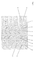
- Fig. 1 and 2 show a profiled tread of a passenger car vehicle tire, which is particularly suitable for use in winter driving conditions, especially on snow or ice.
- the tread consists of a plurality of tread blocks 1, which, arranged in rows, extend over the circumference of the tire, with transverse grooves 2, 2 ', circumferential grooves 3 and oblique grooves 4 delimiting or separating the individual tread blocks 1.
- the tread blocks 1 are each provided with a plurality of at least substantially oriented in profile transverse direction cuts 5, which in the shown Embodiment in plan view have either a wavy or substantially zig-zag-shaped course.
- Such cuts 5 typically have a width between 0.3 mm and 0.6 mm and support the grip, braking and traction properties of the tire on snow and ice.
- tread blocks 1 in particular in further tread outer profile blocks positioned 1, 6 are provided, which are formed in the vulcanization of the green tire in a vulcanization mold by correspondingly preformed mold protrusions.
- the formed in the tread spikelet 6 have in radial section according to Fig. 1a a base portion 6a, a central, in particular circular cylindrical and extending in the radial direction central portion 6b and an opening on the profile top portion 6c, which is too broader to the tread surface, on.
- the execution of the spike holes 6 is known per se and not the subject of the invention.
- Fig. 2 shows a plan view of the tread portion with inserted spikes 7, Fig. 2a a cross section with a spike 7 positioned in a Spikeloch 6.
- the spikes 7 have a base part 8 on which a spike body 9, which is in particular substantially circular cylindrical, is seated.
- the base part 8 can be made circular or oval or oblong in plan view, wherein oval or elongated base parts are usually anchored in relation to the circumferential direction of the tread in the finished tire such that the longitudinal extent of the base part 8 coincides with the circumferential direction of the tire.
- At least the base parts 8 and the spike bodies 9 of the spikes 7 are provided with an adhesive system, in the case of metallic spikes with a rubber-metal adhesive system, the adhesive system being activated after insertion of the spikes 7 into the tread by a separate heat treatment .
- an adhesive system in the case of metallic spikes with a rubber-metal adhesive system, the adhesive system being activated after insertion of the spikes 7 into the tread by a separate heat treatment .
- One of the known adhesive systems may be used in rubber-to-metal adhesive systems such as Parlock, Chemlock or Chemosil.
- the coating of the spikes 7 takes place after a mechanical or chemical cleaning, the thickness of the spike 7 located on the dry adhesive system layer is between 2 microns and 60 microns.
- Fig. 3 shows the basic principle of a spike coating system by Spikes 7, which allows an automated coating of the spikes 7.
- the system has a roller 12 endlessly arranged conveyor belt or an endlessly arranged conveyor chain 11. At least one of the rollers 12 is motorized in rotational movement.
- a receiving station 13 there is a recording of the spikes 7, so that they are hung with their pins 10 on the conveyor chain 11.
- Spikes 7 with a spike body 9 made of aluminum, plastic or ceramic can be magnetically absorbed by means of their metallic spike pins 10.
- the spikes 7 held on the transport chain 11 pass through a first dipping station 14, in which the spikes 7 are treated with a liquid primer. At least the base parts 8 and the spike body 9 are immersed.
- the spikes 7 After leaving the first dipping station 14, the spikes 7 are dried in a warm air stream 14a. The spikes 7 then pass through a second dipping station 15 in which the liquid adhesive system in solution is applied at least to the base parts 8 and the spike bodies 9. After leaving the second dipping station 15, a second drying process takes place, in particular in a warm air stream 15a. The coated spikes 7 are removed from the transport chain 11 at a removal station 16.
- the illustrated drum coating apparatus has a drum 17 which can be set into a rotating or vibrating motion and mounted on a frame 17a, in which the mechanically or chemically pre-cleaned spikes 7 quasi be introduced as bulk material.
- a filling device 18, in particular a hose or a tube first a primer and then the adhesive system, both in solution, introduced and sprayed. After coating any solvent residues are dried by supplying hot air, which is blown through a feed 20, also a hose or a tube. The dry and coated spikes 7 are removed from the drum 17.
- the coated spikes 7 are introduced into the spike holes 6 of the already conventionally produced, vulcanized and thus finished tire, also in a conventional manner. Subsequently, the adhesive system is activated by heating the spikes 7 to a temperature between 90 ° C and 180 ° C for a short period of time between one second and several seconds.
- Fig. 5a and Fig. 5b show a possibility of activation of the adhesive system by means of a contact heater, which has a cross-sectionally U-shaped trough 21, which is designed in a length which corresponds at least to the circumference of the tire to be treated.
- the tub 21 is made of a good thermal conductivity material, in particular a metal alloy.
- a system of pipes 22 is inserted, in which for heating the tub 21 hot steam or other heated gaseous or liquid medium is passed.
- the tub 21 may be heated by means of an electrical heating system recessed in the floor 21a.
- a liquid for example, a molten salt or a molten metal, preferably a lower-temperature melting alloy, such as Sn60PbCu2, may be introduced into the tank 21 to improve the heat transfer.
- the rim-mounted tire 23 is rotatably mounted on a frame 24 which is moved along the trough 21 so that the tire 23 rolls in the trough 21.
- the adhesive system of the spikes 7 is activated and a firm and permanent connection of the spikes 7 made with the tread rubber.
- the tire 23 is off removed the tub 21, freed of any liquid residues and optionally washed with water.
- Fig. 5c shows a variant of the contact heater.
- the approximately U-shaped trough 21 'in cross-section is curved along a circular arc section, in the center of the relevant circle is the center of rotation of the frame 24', which has a connected to the rim of the tire 23 rod 24'a. By rotating the frame 24 'in the circle center of the tire 23 rolls in the tub 21' from.
- the adhesive system applied to the spikes 7 is activated by induction heating.
- Induction heating is based on the principle of energy supply via electromagnetic induction, bringing a coil of suitable dimensions in the vicinity of the heated metal parts. Alternating current with medium to high frequency is applied to this coil, so that in the metal parts parasitic currents arise whose intensity can be controlled. The heating takes place without direct contact and only affects the metallic parts that are to be processed. The transmission is very efficient because no heat is lost.
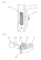
- Fig. 6a to Fig. 6c show the basic structure of a suitable for heating a single spike 7 induction heating device 25.
- This comprises a carrier 26, which consists of a base plate 27 and a cylindrical support 28 connected thereto.
- the carrier 26 is made of a non-metallic, mechanically strong material, such as ceramic, PTFE or PTS.
- An induction coil 29 spirals around the support 28, one of its ends is embedded in the base part 27.
- the base plate 27 has centrally on its underside a recess 27a, which allows placement of the induction heater 25 on the pin 10 of a already positioned in the tread spike 7.
- the high frequency supply is carried out with mounted induction heater 25 by means not shown flexible electrical conductors.
- FIG. 6c shows, by means of a positioning member 30 which is placed on the support 28, are positioned on a spike 7, wherein the carrier 26 under slight contact pressure against the tire is pressed.
- Fig. 7 shows the induction heater 25 in its position at a spike position in a tread block 1 position.
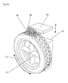
- Fig. 8a to Fig. 8c show schematically a device that allows simultaneous positioning of multiple induction heaters 25 at the spike positions in the tread of a tire 23. Positioning of each individual induction heater 25 is required because of the randomized positioning of the spikes 7 in the tread of the tire.
- the tire 23 is located on a rim 31, which is mounted on a motor-actuated holder 32, so that a partial rotation of the tire 23 can take place.
- On the holder 32 a relative to the tire at least in the radial direction displaceable and positionable carrier platform 33 is arranged, on which two coil arrays 34 and 35 are mounted independently movable.
- the two coil arrays 34 and 35 each comprise a number of induction heating devices 25 aligned in the tread according to the positions of the spikes 7 so that they can be accurately positioned on the spikes 7. After activation of the adhesive systems, the coil arrays 34, 35 are raised, the tire 23 is rotated a bit and the coil arrays 34, 35 are positioned on the next spikes 7.
- a sensor line 36 with Hall sensors can determine in advance the spike positions during a Rohmwindung so that the positioning of the coil arrays 34, 35 can be controlled accordingly.
- Such a device may also have more than two coil arrays.
- a fluorescent agent can be added, which lights at an external irradiation with UV light of a wavelength of, for example, 200 nm to 400 nm. This will allow a subsequent inspection of the bespikten tires.
- the spikes can therefore be marked in this way and it can, for example, different coated spikes or differently constructed spikes are distinguished from each other.
Landscapes
- Engineering & Computer Science (AREA)
- Mechanical Engineering (AREA)
- Tires In General (AREA)
- Tyre Moulding (AREA)
- Adhesives Or Adhesive Processes (AREA)
Abstract
Description
- Die Erfindung betrifft ein Verfahren zum Verankern von Spikes in einem Laufstreifen eines Fahrzeugluftreifens, wobei die Spikes in Spikelöcher im Laufstreifen eingebracht werden, welche bei der Vulkanisation des Reifens in einer Heizpresse eingeformt worden sind. Die Erfindung betrifft ferner Vorrichtungen zur Beschichtung von Spikes mit einem Haftsystem, Vorrichtungen zur Aktivierung des Haftsystems und einen mit Spikes versehenen Fahrzeugluftreifen.
- Spikes werden üblicherweise durch eine Kombination aus Formschluss und Klemmung in den Spikelöchern des Laufstreifens von Fahrzeugluftreifen gehalten und weisen einen Spikekörper aus Metall, insbesondere Stahl, oder aus Kunststoff, auf, in welchem der über die Laufstreifenoberfläche vorstehende Spikepin, welcher insbesondere aus einem Hartmetall besteht, gehalten ist. Spikelöcher und Spikekörper sind geometrisch derart ausgelegt, dass die Pressung des Laufstreifengummis die Spikes an einem unerwünschten Verlassen des Laufstreifens weitgehend hindert.
- Aus der
DE 600 08 625 T2 ist ein Verfahren zur Herstellung eines Fahrzeugluftreifens mit Spikes bekannt, bei welchem die Spikes in der Vulkanisierform des Reifens an speziell vorgesehenen Sitzen eingesetzt sind, der Rohreifen in die Form eingebracht wird und nach dem Schließen der Form der Rohreifen vulkanisiert wird. Dabei werden die Spikes in der Form durch Magneten derart gehalten, dass die erzeugte Magnetkraft in der Lage ist, jeden Spike in seiner vorher festgelegten Position während des Ausformens des Reifens zu fixieren, insbesondere auch während des Einschließens der Spikes in das Laufstreifenmaterial. Die von den in der Form vorhandenen Magneten auf die Spikes ausgeübte Kraft darf jedoch ein Herausziehen des vulkanisierten Reifens aus der Form nicht behindern. Vor ihrem Einsetzen in die Vulkanisationsform werden die Spikes entweder mit einem Haftsystem behandelt oder mit einer Schicht aus einem Haftsystem versehen, wodurch die Haltekraft der Spikes im Laufstreifen erhöht wird. Dieses bekannte Verfahren ist jedoch technisch sehr aufwändig und kostenintensiv. - Bei den herkömmlichen, lediglich durch Formschluss und Pressung des Gummis im Laufstreifen gehaltenen Spikes besteht nach wie vor die Gefahr, dass die Spikes bei hohen Belastungen, wie sie bei bestimmten Bremsmanövern oder schneller Kurvenfahrt auftreten können, verloren gehen.
- Der Erfindung liegt somit die Aufgabe zugrunde, ein Verfahren zur Verfügung zu stellen, welches eine weitgehend belastungsresistente Einbindung von Spikes im Laufstreifen von bereits vulkanisierten Reifen ermöglicht, sodass die Gefahr des Spikeverlustes unter hohen Belastungen reduziert ist. Darüber hinaus soll es die Erfindung ermöglichen, die dem Laufstreifen zu Grunde liegende(n) Kautschukmischung(en) derart auslegen zu können, dass die Wintereigenschaften des Laufstreifens verbessert werden können, ohne auf die für einen guten Presssitz der Spikes in den Spikelöchern erforderlichen Eigenschaften des Laufstreifens zu sehr Rücksicht nehmen zu müssen.
- Gelöst wird die gestellte Aufgabe erfindungsgemäß dadurch, dass die Spikes vor dem Einbringen in den Laufstreifen mit einem Haftsystem beschichtet werden und unter Pressung des Gummimaterials in die Spikelöcher eingebracht werden, wobei anschließend das Haftsystem bei in den Spikelöchern positionierten Spikes durch Wärme aktiviert wird, sodass eine Haftverbindung der Spikes zum Gummimaterial des Laufstreifens hergestellt wird.
- Beim erfindungsgemäßen Verfahren werden die mit einem Haftsystem beschichteten Spikes auf herkömmliche Weise in den Spikelöchern positioniert, erst anschließend wird das Haftsystem aktiviert und dadurch der Spike chemisch und physikalisch in den Laufstreifen eingebunden. Derart eingebundene Spikes sind in der Lage, auch hohen äußeren Belastungen standzuhalten. Die Erfindung ermöglicht außerdem eine nachträgliche und optionale Bespikung von Reifen.
- Bei einer bevorzugten Ausführungsform der Erfindung werden die Spikes in einem Tauchverfahren mit dem Haftsystem beschichtet. Dabei kann derart vorgegangen werden, dass die vorgereinigten Spikes in einen Primer getaucht, anschließend zwischengetrocknet, dann in das Haftsystem getaucht und schließlich getrocknet werden. Alternativ kann auch ein einschichtig aufzubringendes Haftsystem verwendet werden, in diesem Fall ist nur ein Tauchbad erforderlich. Im Rahmen eines Tauchverfahrens ist es ferner möglich, die Spikes komplett zu beschichten oder lediglich die Spikekörper und die Basisteile der Spikes zu beschichten.
- Die zur Beschichtung vorgesehene(n) Flüssigkeit(en) kann bzw. können auch mittels eines Sprühverfahrens aufgebracht werden. Auch in diesem Fall schließt ein Trocknungsvorgang unter Zufuhr von Wärme, beispielsweise warmer Luft, an.
- Um die chemische Haftung der in den Laufstreifen eingebrachten und mit dem Haftsystem beschichteten Spikes durch Ausheizen bzw. Aktivieren des Haftsystems zu bewirken, sind verschiedene vorteilhafte und in der industriellen Fertigung von Reifen rationell einsetzbare Verfahren möglich.
- Bei einem dieser Verfahren wird das Haftsystem auf den Spikes durch Kontaktheizen aktiviert. Es wird daher von außen auf den Reifen Wärme übertragen. Möglich ist dies beispielsweise durch ein Abrollen der Reifen auf einem entsprechend erhitzten Untergrund.
- Eine weitere, vorteilhafte Möglichkeit, das Haftsystem der Spikes zu aktivieren, ist durch Induktionsheizen der Spikes. Dieses Verfahren eignet sich für Spikes mit einem metallischen Spikekörper. Dabei ist es erforderlich, dass jeder einzelne Spike mit einer separaten Induktionsheizeinrichtung erhitzt wird.
- Die Erfindung betrifft ferner Vorrichtungen zur Beschichtung von Spikes mit einem Haftsystem. Für das bereits erwähnte Tauchverfahren eignet sich insbesondere eine Vorrichtung, welche als Komponenten eine in Bewegung versetzbare Transporteinrichtung, an welcher die Spikes gehalten sind, aufweist, ferner zumindest eine Tauchstation zum Aufbringen des Haftsystems, gegebenenfalls eine zweite Tauchstation zum Aufbringen eines flüssigen Primers, sowie zumindest eine Einrichtung zum Trocknen der Spikes. Sind zwei Tauchstationen vorgesehen, erfolgt zwischen den Tauchvorgängen ebenfalls ein Trocknungsvorgang.
- Die oben erwähnte Transporteinrichtung kann beispielsweise ein endlos angeordnetes Transportband oder eine endlos angeordnete Transportkette sein. Diese Transporteinrichtungen sind mit entsprechenden Einrichtungen zum Einfädeln bzw. Aufhängen der Spikes, insbesondere der Spikepins, versehen. Spikes mit metallischen Spikekörpern können an der Transporteinrichtung vorteilhafterweise magnetisch gehalten werden.
- Bei einer alternativen Vorrichtung zur Beschichtung der Spikes mit dem Haftsystem ist eine in Dreh- oder Rüttelbewegung versetzbare Trommel, in welche die zu beschichtenden Spikes quasi als Schüttgut eingebracht werden, vorgesehen, wobei ferner eine Einfülleinrichtung zum Einsprühen der in der Trommel befindlichen Spikes mit dem Haftsystem bzw. gegebenenfalls dem Primer und eine Einrichtung zum Trocknen der beschichteten Spikes in- oder außerhalb der Trommel vorgesehen sind.
- Die Erfindung betrifft ferner Vorrichtungen zur Aktivierung des Haftsystems von Spikes, welche nach dem erfindungsgemäßen Verfahren beschichtet und im Laufstreifen eines Fahrzeugluftreifens verankert worden sind. Eine besonders vorteilhafte Ausführungsvariante einer derartigen Vorrichtung weist eine Wanne auf, deren Länge zumindest der Umfangslänge der zu behandelnden Reifen entspricht und welche aus einem gut wärmeleitfähigen Material besteht sowie einen beheizbaren Boden aufweist. Mit einer derartigen Vorrichtung lässt sich ein Kontaktheizen des Haftsystems beim Abrollen der Reifen bewerkstelligen.
- Die Beheizung des Bodens der Wanne lässt sich mit einem in den Boden eingelassenen Rohrleitungssystem durchführen. Durch dieses Rohrleitungssystem kann eine erhitzte Flüssigkeit oder auch heißer Dampf geleitet werden. Alternativ dazu kann der Boden mit einer elektrischen Heizung versehen sein.
- Eine Ausführungsform einer Vorrichtung, welche eine Aktivierung des Haftsystems der bereits im Laufstreifen eingesetzten Spikes durch Induktionsheizen ermöglicht, besteht aus zumindest einer auf einem Spike positionierbaren Induktionsheizeinrichtung. Es ist somit jeder Spike separat über eine bzw. die Induktionsheizeinrichtung zu erhitzen. Eine zweckmäßige und einfach Ausführungsvariante einer solchen Induktionsheizeinrichtung weist einen nicht metallischen Träger und eine an diesem Träger gehaltene Induktionsspule auf, wobei es von Vorteil ist, wenn die Induktionsspule zumindest zum Teil im Träger eingebettet ist.
- Werden in dieser Vorrichtung mehrere Induktionsheizeinrichtungen in zumindest einem Spulenarray zusammengefasst, so können die Induktionsheizeinrichtungen bereits auf mehreren Spikes vorpositioniert werden. Es kann eine Sensoreinrichtung vorgesehen sein, mittels welcher durch Drehung des Reifens die Spikepositionen feststellbar sind, entsprechend gespeichert und in einem Rechner verarbeitet werden, sodass die Induktionsheizeinrichtungen automatisch entsprechend der Spikepositionen angeordnet werden.
- Die Erfindung betrifft ferner einen Fahrzeugluftreifen mit Spikes, welche nach dem erfindungsgemäßen Verfahren verankert worden sind.
- Weitere Merkmale, Vorteile und Einzelheiten der Erfindung werden anhand der schematischen Zeichnung, die Ausführungsbeispiele darstellt, näher beschrieben. Dabei zeigen
-
Fig. 1 eine Draufsicht auf einen Abschnitt eines profilierten Laufstreifens eines Fahrzeugluftreifens mit unbespikten Spikelöchern, -
Fig. 1a einen Schnitt entlang der Linie I-I derFig. 1 , -
Fig. 2 den Laufstreifenabschnitt ausFig. 1 mit eingesetzten Spikes, -
Fig. 2a einen Schnitt entlang der Linie II-II derFig. 2 , -
Fig. 3 ein Basiskonzept einer Tauchbeschichtungsanlage für Spikes, -
Fig. 4 ein Basiskonzept einer Trommelbeschichtungsvorrichtung für Spikes, -
Fig. 5a undFig. 5b Ansichten einer Kontaktheizvorrichtung, -
Fig. 5c eine Variante der Kontaktheizvorrichtung, -
Fig. 6a bis Fig. 6d unterschiedliche Ansichten einer Ausführungsvariante einer Induktionsheizeinrichtung, -
Fig. 7 eine über einem Profilblock positionierte Induktionsheizeinrichtung und -
Fig. 8a bis Fig. 8c unterschiedliche Ansichten einer mehrere Induktionsheizeinrichtungen aufweisenden Induktionsheizvorrichtung. -
Fig. 1 und2 zeigen einen profilierten Laufstreifen eines für Personenkraftwagen vorgesehenen Fahrzeugluftreifens, welcher für einen Einsatz unter winterlichen Fahrbedingungen, insbesondere auf Schnee oder Eis, besonders geeignet ist. Der Laufstreifen besteht aus einer Vielzahl von Profilblöcken 1, welche, in Reihen angeordnet, über den Umfang des Reifens verlaufen, wobei Quernuten 2, 2', Umfangsnuten 3 und Schrägrillen 4 die einzelnen Profilblöcke 1 begrenzen bzw. voneinander trennen. Der Verlauf der Nuten 2, 2', 3 und Rillen 4 bestimmt die in Draufsicht vorliegende unterschiedliche Gestalt der Profilblöcke 1. Wie bei Winterreifen üblich sind die Profilblöcke 1 jeweils mit einer Vielzahl von zumindest im Wesentlichen in Profilquerrichtung orientierten Einschnitten 5 versehen, die bei der gezeigten Ausführungsform in Draufsicht entweder einem wellenförmigen oder im Wesentlichen zick-zack-förmigen Verlauf aufweisen. Solche Einschnitte 5 weisen üblicherweise eine Breite zwischen 0,3 mm und 0,6 mm auf und unterstützen die Griff- Brems- und Traktionseigenschaften des Reifens auf Schnee und Eis. Nachdem die Ausgestaltung des Laufstreifens nicht Gegenstand dieser Erfindung ist, wird auf sie im Detail nicht näher eingegangen. - In einer Anzahl von Profilblöcken 1, insbesondere in weiter laufstreifenaußenseitig positionierten Profilblöcken 1, sind Spikelöcher 6 vorhanden, welche bei der Vulkanisation des Rohreifens in einer Vulkanisationsform durch entsprechend vorgeformte Formvorsprünge ausgebildet werden. Die im Laufstreifen ausgebildeten Spikelöcher 6 weisen im radialen Schnitt gemäß
Fig. 1a einen Basisabschnitt 6a, einen zentralen, insbesondere kreiszylindrisch und sich in radialer Richtung sich erstreckenden zentralen Abschnitt 6b und einen an der Profiloberseite mündenden Abschnitt 6c, welcher zur Laufstreifenoberfläche zu breiter wird, auf. Die Ausführung der Spikelöcher 6 ist an sich bekannt und nicht Gegenstand der Erfindung. -
Fig. 2 zeigt eine Draufsicht auf den Laufstreifenabschnitt mit eingesetzten Spikes 7,Fig. 2a einen Querschnitt mit einem in einem Spikeloch 6 positionierten Spike 7. - Die Spikes 7 weisen einen Basisteil 8 auf, auf welchem ein insbesondere im Wesentlichen kreiszylindrischer Spikekörper 9 sitzt. Im Spikekörper 9 ist der ebenfalls zylindrische, jedoch mit einem kleineren Durchmesser als der Spikekörper 9 versehene Pin 10 verankert. Der Basisteil 8 kann in Draufsicht kreisrund oder oval bzw. länglich ausgeführt sein, wobei ovale bzw. längliche Basisteile üblicherweise in Bezug auf die Umfangsrichtung des Laufstreifens im fertigen Reifen derart verankert werden, dass die Längserstreckung des Basisteils 8 mit der Umfangsrichtung des Reifens übereinstimmt. Zumindest die Basisteile 8 und die Spikekörper 9 der Spikes 7 werden mit einem Haftsystem, bei metallischen Spikes mit einem Gummi-Metall-Haftsystem, versehen bzw. beschichtet, wobei das Haftsystem nach dem Einsetzen der Spikes 7 in den Laufstreifen durch eine gesonderte Wärmebehandlung aktiviert wird. Es kann eines der bekannten Haftsysteme, bei Gummi-Metall-Haftsystemen beispielsweise Parlock, Chemlock oder Chemosil, verwendet werden. Die Beschichtung der Spikes 7 erfolgt im Anschluss an eine mechanische oder chemische Reinigung, wobei die Dicke der am Spike 7 befindlichen, trockenen Haftsystemschicht zwischen 2 µm und 60 µm beträgt.
-
Fig. 3 zeigt das Grundprinzip einer Tauchbeschichtungsanlage von Spikes 7, welche eine automatisierte Beschichtung der Spikes 7 ermöglicht. Die Anlage weist ein an Rollen 12 endlos angeordnetes Transportband bzw. eine endlos angeordnete Transportkette 11 auf. Zumindest eine der Rollen 12 ist motorisch in Drehbewegung versetzbar. An einer Aufnahmestation 13 erfolgt eine Aufnahme der Spikes 7, sodass diese mit ihren Pins 10 an der Transportkette 11 aufgehängt sind. Spikes 7 mit einem Spikekörper 9 aus Aluminium, Kunststoff oder Keramik, können mittels ihrer metallischen Spikepins 10 magnetisch aufgenommen werden. Die an der Transportkette 11 gehaltenen Spikes 7 durchlaufen eine erste Tauchstation 14, in welcher die Spikes 7 mit einem flüssigen Primer behandelt werden. Dabei werden zumindest die Basisteile 8 und die Spikekörper 9 eingetaucht. Nach Verlassen der ersten Tauchstation 14 werden die Spikes 7 in einem warmen Luftstrom 14a getrocknet. Anschließend durchlaufen die Spikes 7 eine zweite Tauchstation 15, in welcher zumindest auf die Basisteile 8 und die Spikekörper 9 das in Lösung befindliche flüssige Haftsystem aufgebracht wird. Nach dem Verlassen der zweiten Tauchstation 15 erfolgt ein zweiter Trocknungsvorgang, insbesondere in einem warmen Luftstrom 15a. Die beschichteten Spikes 7 werden der Transportkette 11 bei einer Entnahmestation 16 entnommen. - Eine weitere Möglichkeit, die Spikes 7 mit einem Haftsystem zu beschichten, zeigt
Fig. 4 . Die dargestellte Trommelbeschichtungsvorrichtung weist eine in eine Dreh- oder Rüttelbewegung versetzbare, auf einem Gestell 17a gelagerte Trommel 17 auf, in welcher die mechanisch oder chemisch vorgereinigten Spikes 7 quasi als Schüttgut eingebracht werden. Über eine Einfülleinrichtung 18, insbesondere einen Schlauch oder ein Rohr, wird zuerst ein Primer und anschließend das Haftsystem, beides in Lösung, eingebracht und aufgesprüht. Nach der Beschichtung werden etwaige Lösungsmittelreste durch Zufuhr von Warmluft, welche über eine Zuführung 20, ebenfalls ein Schlauch oder ein Rohr, eingeblasen wird, abgetrocknet. Die trockenen und beschichteten Spikes 7 werden der Trommel 17 entnommen. - Die beschichteten Spikes 7 werden in die Spikelöcher 6 des bereits in herkömmlicher Weise hergestellten, vulkanisierten und somit fertigen Reifens, ebenfalls auf herkömmliche Weise, eingebracht. Anschließend erfolgt eine Aktivierung des Haftsystems durch Erwärmung der Spikes 7 auf eine Temperatur zwischen 90 °C und 180 °C für einen kurzen Zeitraum zwischen einer Sekunde und mehreren Sekunden.
-
Fig. 5a undFig. 5b zeigen eine Möglichkeit der Aktivierung des Haftsystems mittels einer Kontaktheizvorrichtung, welche eine im Querschnitt U-förmige Wanne 21 aufweist, die in einer Länge ausgeführt ist, die zumindest dem Umfang der zu behandelnden Reifen entspricht. Die Wanne 21 besteht aus einem gut wärmeleitfähigen Material, insbesondere einer Metalllegierung. Im Boden 21a der Wanne 21 ist ein System von Rohrleitungen 22 eingelassen, in welche zum Erhitzen der Wanne 21 heißer Dampf oder ein anderes erhitztes gasförmiges oder flüssiges Medium geleitet wird. Alternativ kann die Wanne 21 mittels eines im Boden 21a eingelassenen elektrischen Heizsystems erhitzt werden. Zusätzlich kann in die Wanne 21 zur Verbesserung des Wärmetransportes eine Flüssigkeit, beispielsweise eine Salzschmelze oder eine Metallschmelze, vorzugsweise eine bei niedrigerer Temperatur schmelzende Legierung wie Sn60PbCu2, eingefüllt werden. - Der auf einer Felge befindliche Reifen 23 wird drehbar an einem Gestell 24 angeordnet, welches entlang der Wanne 21 bewegt wird, sodass der Reifen 23 in der Wanne 21 abrollt. Dabei wird das Haftsystem der Spikes 7 aktiviert und eine feste und dauerhafte Verbindung der Spikes 7 mit dem Laufstreifengummi hergestellt. Der Reifen 23 wird aus der Wanne 21 entfernt, von etwaigen Flüssigkeitsresten befreit und gegebenenfalls mit Wasser gewaschen.
-
Fig. 5c zeigt eine Variante der Kontaktheizvorrichtung. Die im Querschnitt etwa U-förmige Wanne 21' ist entlang eines Kreisbogenabschnittes gekrümmt, im Mittelpunkt des diesbezüglichen Kreises befindet sich der Drehmittelpunkt des Gestells 24', welches eine mit der Felge des Reifens 23 verbundene Stange 24'a aufweist. Durch Drehen des Gestells 24' im Kreismittelpunkt rollt der Reifen 23 in der Wanne 21' ab. - Bei einer weiteren Ausführungsform der Erfindung wird das auf die Spikes 7 aufgebrachte Haftsystem durch Induktionsheizen aktiviert. Induktionsheizen basiert auf dem Prinzip der Energiezufuhr über elektromagnetische Induktion, wobei eine Spule von passenden Abmessungen in die Nähe der aufzuheizenden Metallteile gebracht wird. An diese Spule wird Wechselstrom mit mittlerer bis hoher Frequenz angelegt, sodass in den Metallteilen parasitäre Ströme entstehen, deren Intensität gesteuert werden kann. Die Heizung erfolgt ohne direkten Kontakt und wirkt nur auf die metallischen Teile, die bearbeitet werden sollen. Die Übertragung ist sehr effizient, da keine Wärme verloren geht.
-
Fig. 6a bis Fig. 6c zeigen den grundsätzlichen Aufbau einer zum Beheizen eines einzelnen Spikes 7 geeigneten Induktionsheizeinrichtung 25. Diese weist einen Träger 26 auf, welcher aus einer Basisscheibe 27 und aus einer mit diesem verbundenen, zylindrischen Stütze 28 besteht. Der Träger 26 besteht aus einem nichtmetallischen, mechanisch festen Material, beispielsweise Keramik, PTFE oder PTS. Eine Induktionsspule 29 umläuft spiralförmig die Stütze 28, eines ihrer Enden ist im Basisteil 27 eingebettet. Die Basisscheibe 27 weist an ihrer Unterseite mittig eine Ausnehmung 27a auf, die ein Aufsetzen der Induktionsheizeinrichtung 25 auf den Pin 10 eines bereits im Laufstreifen positionierten Spikes 7 gestattet. Die Hochfrequenzzufuhr erfolgt bei aufgesetzter Induktionsheizeinrichtung 25 mittels nicht gezeigter flexibler elektrischer Leiter. Zusätzlich kann die Induktionsheizeinrichtung 25, wie esFig. 6c zeigt, mittels eines Positionierelementes 30, welches auf die Stütze 28 aufgesetzt wird, auf einem Spike 7 positioniert werden, wobei der Träger 26 unter geringem Anpressdruck gegen den Reifen gedrückt wird.Fig. 7 zeigt die Induktionsheizeinrichtung 25 in ihrer an einer Spikeposition in einem Profilblock 1 positionierten Lage. -
Fig. 8a bis Fig. 8c zeigen schematisch eine Vorrichtung, die ein gleichzeitiges Positionieren mehrerer Induktionsheizeinrichtungen 25 an den Spikepositionen im Laufstreifen eines Reifens 23 ermöglicht. Eine Positionierung jeder einzelnen Induktionsheizeinrichtung 25ist wegen der randomisierten Positionierung der Spikes 7 im Laufstreifen des Reifen erforderlich. Der Reifen 23 befindet sich auf einer Felge 31, die an einer motorisch betätigbaren Halterung 32 gelagert ist, sodass eine abschnittsweise Drehung des Reifens 23 erfolgen kann. An der Halterung 32 ist eine bezogen auf den Reifen zumindest in radialer Richtung verschiebbare und positionierbare Trägerplattform 33 angeordnet, auf welcher zwei Spulenarrays 34 und 35 voneinander unabhängig bewegbar gelagert sind. Die beiden Spulenarrays 34 und 35 umfassen jeweils eine Anzahl von entsprechend der Positionen der Spikes 7 im Laufstreifen ausgerichteten Induktionsheizeinrichtungen 25, sodass diese auf den Spikes 7 exakt positioniert werden können. Nach der Aktivierung der Haftsysteme werden die Spulenarrays 34, 35 angehoben, der Reifen 23 ein Stück gedreht und die Spulenarrays 34, 35 auf den nächsten Spikes 7 positioniert. Eine Sensorzeile 36 mit Hallsensoren kann vorab die Spikepositionen während einer Radumdrehung ermitteln, sodass die Positionierung der Spulenarrays 34, 35 entsprechend gesteuert werden kann. Eine derartige Vorrichtung kann auch mehr als zwei Spulenarrays aufweisen. - Es sind weitere Verfahren möglich, das Haftsystem der Spikes zu aktivieren, beispielweise durch äußeres Erwärmen des Reifens in einem Umluftofen oder einem Mikrowellenofen, Erwärmung mit Infrarotstrahlung, Heißluft, Heißwasser, Heißdampf, durch Ultraschall, Laser oder Hochfrequenz.
- Dem Haftsystem kann ein Fluoreszenzmittel zugesetzt werden, welches bei einer äußeren Bestrahlung mit UV-Licht einer Wellenlänge von beispielsweise 200 nm bis 400 nm leuchtet. Dadurch wird eine nachträgliche Inspektion der bespikten Reifen ermöglicht. Je nach Fluoreszenzmittel kann auch die Farbe des fluoreszierenden Lichts variiert werden. Die Spikes können daher auf diese Weise markiert sein und es können beispielsweise unterschiedlich beschichtete Spikes oder unterschiedlich aufgebaute Spikes voneinander unterschieden werden.
-
- 1
- Profilblock
- 2
- Quernut
- 2'
- Quernut
- 3
- Umfangsnut
- 4
- Schrägrille
- 5
- Einschnitt
- 6
- Spikeloch
- 6a
- Basisabschnitt
- 6b
- zentraler Abschnitt
- 6c
- oberer Abschnitt
- 7
- Spike
- 8
- Basisteil
- 9
- Spikekörper
- 10
- Pin
- 11
- Transportkette
- 12
- Rolle
- 13
- Aufnahmestation
- 14
- Erste Tauchstation
- 14a
- Luftstrom
- 15
- Zweite Tauchstation
- 15a
- Luftstrom
- 16
- Entnahmestation
- 17
- Trommel
- 17a
- Gestell
- 18
- Einfüllöffnung
- 19
- Felge
- 20
- Einfüllöffnung
- 21
- Wanne
- 21a
- Boden
- 21'
- Wanne
- 22
- Rohrleitung
- 23
- ...... Reifen
- 24
- Gestell
- 24'
- ..... Gestell
- 24'a
- Stange
- 25
- Induktionsheizeinrichtung
- 26
- Träger
- 27
- Basisscheibe
- 27a
- Ausnehmung
- 28
- Stütze
- 29
- Spule
- 30
- Positionierelement
- 31
- Felge
- 32
- Halterung
- 33
- Träger
- 34
- Spulenarray
- 35
- Spulenarray
- 36
- Sensorzeile
Claims (22)
- Verfahren zum Verankern von Spikes (7) in einem Laufstreifen eines Fahrzeugluftreifens, wobei die Spikes (7, 7') jeweils einen Basisteil (8, 8'), einen Spikekörper (9, 9') und einen Pin (10, 10') aufweisen und in Spikelöcher (6) im Laufstreifen eingebracht werden, welche bei der Vulkanisation des Reifens in einer Heizpresse eingeformt worden sind,
dadurch gekennzeichnet,
dass die Spikes (7, 7') vor dem Einbringen in den Laufstreifen mit einem Haftsystem beschichtet werden und unter Pressung des Gummimaterials in die Spikelöcher (6) eingebracht werden, wobei anschließend das Haftsystem bei in den Spikelöchern (6) positionierten Spikes (7, 7') durch Wärme aktiviert wird, sodass eine Haftverbindung der Spikes (7, 7') zum Gummimaterial des Laufstreifens hergestellt wird. - Verfahren nach Anspruch 1, dadurch gekennzeichnet, dass das Haftsystem durch Eintauchen der Spikes (7) aufgebracht wird und die Spikes anschließend getrocknet werden.
- Verfahren nach Anspruch 1 oder 2, dadurch gekennzeichnet, dass lediglich die Spikekörper (9) und die Basisteile (8) der Spikes (7) beschichtet werden.
- Verfahren nach Anspruch 1, dadurch gekennzeichnet, dass die Spikes (7) mit dem Haftsystem besprüht und anschließend getrocknet werden.
- Verfahren nach einem der Ansprüche 1 bis 4, dadurch gekennzeichnet, dass das auf die Spikes (7) aufgebrachte Haftsystem durch Kontaktheizen aktiviert wird.
- Verfahren nach Anspruch 5, dadurch gekennzeichnet, dass der Reifen auf einem erhitzten Untergrund abgerollt wird.
- Verfahren nach einem der Ansprüche 1 bis 4, dadurch gekennzeichnet, dass das auf die Spikes (7) aufgebrachte Haftsystem durch Heißluft, Heißdampf oder Heißwasser aktiviert wird.
- Verfahren nach einem der Ansprüche 1 bis 4, dadurch gekennzeichnet, dass das auf die Spikes (7) aufgebrachte Haftsystem durch ein Induktionsheizen der Spikes (7) aktiviert wird.
- Verfahren nach Anspruch 8, dadurch gekennzeichnet, dass jeder Spike (7) mit einer separaten Induktionsheizeinrichtung (25) erhitzt wird.
- Vorrichtung zur Beschichtung von Spikes (7) mit einem Haftsystem, welche Vorrichtung folgende Komponenten aufweist:- eine in Bewegung versetzbare Transporteinrichtung (11), an welcher die Spikes (7) gehalten sind,- zumindest eine Tauchstation (14) zur Beschichtung der Spikes (7) mit einem flüssigen Haftsystem, gegebenenfalls zur Vorbehandlung mit einem Primer,- zumindest eine Einrichtung (14a, 15a) zum Trocknen der Spikes (7).
- Vorrichtung nach Anspruch 10, dadurch gekennzeichnet, dass die Transporteinrichtung ein endlos angeordnetes Transportband (11) oder eine endlos angeordnete Transportkette ist.
- Vorrichtung nach Anspruch 10 oder 11, dadurch gekennzeichnet, dass die Spikes (7) am Transportband (11) bzw. an der Transportkette magnetisch gehalten sind.
- Vorrichtung zur Beschichtung von Spikes (7) mit einem Haftsystem, welche Vorrichtung folgende Komponenten aufweist:- eine in Dreh- oder Rüttelbewegung versetzbare Trommel (17), in welche die zu beschichtenden Spikes (7) als Schüttgut eingebracht werden,- zumindest eine Einfülleinrichtung (18) zum Einsprühen der Spikes (7) in der Trommel (17) mit dem Haftsystem, gegebenenfalls zur Vorbehandlung mit einem Primer,- eine Einrichtung zum Trocknen der beschichteten Spikes (7) in oder außerhalb der Trommel (17).
- Vorrichtung zur Aktivierung des Haftsystems von Spikes (7), welche nach dem Verfahren gemäß einem oder mehreren der Ansprüche 1 bis 6 im Laufstreifen eines Fahrzeugluftreifens verankert werden,
dadurch gekennzeichnet,
dass die Vorrichtung eine Wanne (21, 21') aufweist, deren Länge zumindest der Umfangslänge des zu behandelnden Reifens entspricht und welche aus einem gut wärmeleitenden Material besteht sowie einen beheizbaren Boden (21a) aufweist. - Vorrichtung nach Anspruch 14, dadurch gekennzeichnet, dass der Boden (21a) der Wanne (21) mit einem Rohrleitungssystem versehen ist.
- Vorrichtung nach Anspruch 14, dadurch gekennzeichnet, dass der Boden (21a) der Wanne (21) elektrisch beheizbar ist.
- Vorrichtung zur Aktivierung des Haftsystems von Spikes (7), welche nach dem Verfahren gemäß einem oder mehreren der Ansprüche 1 bis 4 sowie 8 und 9 im Laufstreifen eines Fahrzeugluftreifens verankert werden,
dadurch gekennzeichnet,
dass die Vorrichtung zumindest eine auf einem Spike (7) positionierbare Induktionsheizeinrichtung (25) aufweist. - Vorrichtung nach Anspruch 17, dadurch gekennzeichnet, dass die Induktionsheizeinrichtung (25) einen nicht metallischen Träger (26) und eine an diesem gehaltene Induktionsspule (29) aufweist.
- Vorrichtung nach Anspruch 18, dadurch gekennzeichnet, dass die Induktionsspule (29) zum Teil im Träger (26) eingebettet ist.
- Vorrichtung nach einem der Ansprüche 17 bis 19, dadurch gekennzeichnet, dass mehrere Induktionsheizeinrichtungen (25) in zumindest einem Spulenarray (34, 35) zusammengefasst sind und gemäß der Anordnung einer entsprechenden Anzahl von Spikes (7) vorpositionierbar sind.
- Vorrichtung nach Anspruch 18, dadurch gekennzeichnet, dass das/die Spulenarray(s) (34, 35) an einem verfahrbaren Träger (33) gelagert ist bzw. sind, welcher an einer Halterung angeordnet ist.
- Fahrzeugluftreifen mit Spikes, welche gemäß dem Verfahren nach einem oder mehreren der Ansprüche 1 bis 9 verankert worden sind.
Priority Applications (1)
| Application Number | Priority Date | Filing Date | Title |
|---|---|---|---|
| EP14169837.3A EP2777923A1 (de) | 2009-05-27 | 2009-11-30 | Verfahren und Vorrichtung zum Beschichten von Spikes |
Applications Claiming Priority (1)
| Application Number | Priority Date | Filing Date | Title |
|---|---|---|---|
| DE200910025874 DE102009025874A1 (de) | 2009-05-27 | 2009-05-27 | Verfahren zum Verankern von Spikes im Laufstreifen eines Fahrzeugluftreifens |
Related Child Applications (1)
| Application Number | Title | Priority Date | Filing Date |
|---|---|---|---|
| EP14169837.3A Division EP2777923A1 (de) | 2009-05-27 | 2009-11-30 | Verfahren und Vorrichtung zum Beschichten von Spikes |
Publications (3)
| Publication Number | Publication Date |
|---|---|
| EP2255959A2 true EP2255959A2 (de) | 2010-12-01 |
| EP2255959A3 EP2255959A3 (de) | 2011-03-30 |
| EP2255959B1 EP2255959B1 (de) | 2014-06-25 |
Family
ID=42537567
Family Applications (2)
| Application Number | Title | Priority Date | Filing Date |
|---|---|---|---|
| EP20090177433 Not-in-force EP2255959B1 (de) | 2009-05-27 | 2009-11-30 | Verfahren zum Verankern von Spikes im Laufstreifen eines Fahrzeugluftreifens |
| EP14169837.3A Ceased EP2777923A1 (de) | 2009-05-27 | 2009-11-30 | Verfahren und Vorrichtung zum Beschichten von Spikes |
Family Applications After (1)
| Application Number | Title | Priority Date | Filing Date |
|---|---|---|---|
| EP14169837.3A Ceased EP2777923A1 (de) | 2009-05-27 | 2009-11-30 | Verfahren und Vorrichtung zum Beschichten von Spikes |
Country Status (2)
| Country | Link |
|---|---|
| EP (2) | EP2255959B1 (de) |
| DE (1) | DE102009025874A1 (de) |
Cited By (2)
| Publication number | Priority date | Publication date | Assignee | Title |
|---|---|---|---|---|
| RU2676367C2 (ru) * | 2015-11-11 | 2018-12-28 | Нокиан Ренкаат Ойй | Способ изготовления автомобильной шины |
| RU2718199C2 (ru) * | 2015-10-27 | 2020-03-31 | Нокиан Ренкаат Ойй | Способ ошиповки шины транспортного средства |
Families Citing this family (4)
| Publication number | Priority date | Publication date | Assignee | Title |
|---|---|---|---|---|
| DE102022204502A1 (de) | 2022-05-06 | 2023-11-09 | Continental Reifen Deutschland Gmbh | Spikesetzvorrichtung mit Injektionsspreizfinger |
| DE102023212196A1 (de) | 2023-12-04 | 2025-06-05 | Continental Reifen Deutschland Gmbh | Fahrzeugluftreifen |
| DE102023212195A1 (de) | 2023-12-04 | 2025-06-05 | Continental Reifen Deutschland Gmbh | Formstift, Vulkanisierungsvorrichtung und Fahrzeugluftreifen |
| DE102023212438A1 (de) | 2023-12-11 | 2025-06-12 | Continental Reifen Deutschland Gmbh | Fahrzeugluftreifen und Verfahren zu seiner Herstellung |
Citations (4)
| Publication number | Priority date | Publication date | Assignee | Title |
|---|---|---|---|---|
| GB968003A (en) | 1961-01-11 | 1964-08-26 | Continental Gummi Werke Ag | Pneumatic vehicle tyre and method for its production |
| JPH071605A (ja) | 1993-06-16 | 1995-01-06 | Sumitomo Rubber Ind Ltd | 氷雪路用更生タイヤおよびその製造方法 |
| DE60008625T2 (de) | 1999-05-26 | 2005-02-10 | Pirelli Pneumatici S.P.A. | Verfahren zur Herstellung eines Spike-Reifens und Formwerkzeug dafür |
| JP2008207743A (ja) | 2007-02-27 | 2008-09-11 | Yokohama Rubber Co Ltd:The | スタッドタイヤ及びその製造方法 |
Family Cites Families (17)
| Publication number | Priority date | Publication date | Assignee | Title |
|---|---|---|---|---|
| GB190704069A (en) * | 1907-02-19 | 1907-11-28 | Louis Callender | Improvements connected with the Attachment of Studs or Rivets to Pneumatic Tyres of Motor or other Road Vehicles. |
| DE1579111A1 (de) * | 1963-07-18 | 1969-05-29 | Continental Gummi Werke Ag | Verfahren zur Herstellung von Fahrzeugluftreifen mit Gleitschutzkoerpern |
| US3485132A (en) * | 1965-08-02 | 1969-12-23 | Ncr Co | Driven,headed,and screw-threaded fastenings |
| US3407860A (en) * | 1966-02-23 | 1968-10-29 | Coral W. Mossberg | Safety spike for vehicle tires |
| DE1680487A1 (de) * | 1966-12-05 | 1972-01-13 | Simon Fa Karl | Spike fuer Kraftfahrzeugreifen und Verfahren zu seiner Herstellung |
| US3911986A (en) * | 1972-11-03 | 1975-10-14 | Kennametal Inc | Anti-skid element for a vehicle tire |
| CA1044961A (en) * | 1973-06-18 | 1978-12-26 | Joseph D. Nessar | Apparatus and method for surface treating metal articles |
| ZA76914B (en) * | 1976-02-16 | 1977-09-28 | Dome Inventions Pty Ltd | Method and apparatus for embedding tyre chains in the tread portion of a tyre |
| US4325320A (en) * | 1978-11-09 | 1982-04-20 | Japan Envirotic Industry Co., Ltd. | Apparatus employed in surface treatment |
| JPS5851134A (ja) * | 1981-09-21 | 1983-03-25 | Sumitomo Rubber Ind Ltd | スパイクタイヤの製造方法 |
| CH671271A5 (en) * | 1986-07-07 | 1989-08-15 | Ebnoether Ag | Fixing element for hammering in partic. nail or clamp - has coating on shaft comprising vinyl] acetate copolymer, acrylate] or methacrylate]-unsatd. acid copolymer, opt. polyvinyl alcohol, etc. |
| US4844137A (en) * | 1988-04-21 | 1989-07-04 | Einar Einarsson | Self-adjusting tire stud |
| SU1669770A1 (ru) * | 1988-06-13 | 1991-08-15 | А.Г.Сучков | Способ ошиповки покрышки колеса транспортного средства |
| RU2106262C1 (ru) * | 1997-01-10 | 1998-03-10 | Акционерное общество открытого типа "Нижнекамскшина" | Способ изготовления шипованных автомобильных шин |
| AU3586299A (en) * | 1997-11-26 | 1999-06-15 | Wm. Wrigley Jr. Company | Device and method for coating products |
| ES2251583T3 (es) * | 2002-03-29 | 2006-05-01 | Pirelli Pneumatici S.P.A. | Procedimiento y dispositivo para la fabricacion de un neumatico esculpido. |
| DE102004039755A1 (de) * | 2004-08-17 | 2006-03-09 | Assmus Metallveredelung Gmbh | Vorrichtung für die Oberflächenbehandlung von Massenteilen |
-
2009
- 2009-05-27 DE DE200910025874 patent/DE102009025874A1/de not_active Withdrawn
- 2009-11-30 EP EP20090177433 patent/EP2255959B1/de not_active Not-in-force
- 2009-11-30 EP EP14169837.3A patent/EP2777923A1/de not_active Ceased
Patent Citations (4)
| Publication number | Priority date | Publication date | Assignee | Title |
|---|---|---|---|---|
| GB968003A (en) | 1961-01-11 | 1964-08-26 | Continental Gummi Werke Ag | Pneumatic vehicle tyre and method for its production |
| JPH071605A (ja) | 1993-06-16 | 1995-01-06 | Sumitomo Rubber Ind Ltd | 氷雪路用更生タイヤおよびその製造方法 |
| DE60008625T2 (de) | 1999-05-26 | 2005-02-10 | Pirelli Pneumatici S.P.A. | Verfahren zur Herstellung eines Spike-Reifens und Formwerkzeug dafür |
| JP2008207743A (ja) | 2007-02-27 | 2008-09-11 | Yokohama Rubber Co Ltd:The | スタッドタイヤ及びその製造方法 |
Cited By (2)
| Publication number | Priority date | Publication date | Assignee | Title |
|---|---|---|---|---|
| RU2718199C2 (ru) * | 2015-10-27 | 2020-03-31 | Нокиан Ренкаат Ойй | Способ ошиповки шины транспортного средства |
| RU2676367C2 (ru) * | 2015-11-11 | 2018-12-28 | Нокиан Ренкаат Ойй | Способ изготовления автомобильной шины |
Also Published As
| Publication number | Publication date |
|---|---|
| EP2255959A3 (de) | 2011-03-30 |
| EP2255959B1 (de) | 2014-06-25 |
| DE102009025874A1 (de) | 2010-12-02 |
| EP2777923A1 (de) | 2014-09-17 |
Similar Documents
| Publication | Publication Date | Title |
|---|---|---|
| EP2255959B1 (de) | Verfahren zum Verankern von Spikes im Laufstreifen eines Fahrzeugluftreifens | |
| EP1985435B1 (de) | Verfahren und Vorrichtung zur Herstellung einer Felge | |
| DE60008625T2 (de) | Verfahren zur Herstellung eines Spike-Reifens und Formwerkzeug dafür | |
| DE60015868T2 (de) | Verfahren zur Befestigung eines Gegenstandes an der Innenseite eines Luftreifens | |
| EP3140069B1 (de) | Verfahren und vorrichtung zum fügen eines verbundblechbauteils mit einem weiteren bauteil | |
| EP3307508B1 (de) | Verfahren zur verstärkung einer grundstruktur | |
| DE102018002545A1 (de) | Verfahren zum Abschneiden eines Extrudates | |
| DE69822489T2 (de) | Verfahren und gerät zum thermischen verbinden | |
| DE1301045B (de) | Verfahren zur Herstellung eines Luftreifens | |
| DE60206663T2 (de) | Verfahren und vorrichtung zur herstellung eines spike-reifens | |
| EP3275702B1 (de) | Befestigungsvorrichtung zum befestigen eines messsensors, insbesondere reifendrucksensors, und verfahren zum montieren eines messsensors | |
| EP2509780B1 (de) | Verfahren und vorrichtung zum aktivieren eines haftsystems von spikes | |
| DE19854735B4 (de) | Verfahren zum Herstellen einer Hülse aus thermisch verformbaren Material | |
| EP2639085B1 (de) | Verfahren zum Verankern eines Containers für temperatursensible Elektronik im Laufstreifen eines Fahrzeugreifens | |
| EP3651977B1 (de) | Verfahren zur verwendung beim aufrauen eines für eine kaltrunderneuerung vorgesehenen profilierten laufstreifens | |
| DE3301490A1 (de) | Verfahren und vorrichtung zum runderneuern von fahrzeugreifen | |
| AT506932B1 (de) | Verfahren zum abdichten eines rohrabschnittes | |
| DE19955751C1 (de) | Verfahren und Vorrichtung zur Vorwärmung eines Rohrstrangs im Bereich von Rundschweißnähten | |
| DE19750150A1 (de) | Vorrichtung für plattgefahrene Luftreifen eines Kraftfahrzeugs | |
| DE102016111305B4 (de) | Verfahren und Vorrichtung zum Aufschweißen einer Schicht aus einem Kunststoffmaterial auf ein Kunststoffrohr | |
| DE102005023331A1 (de) | Druckzylinder und Verfahren zur Herstellung eines Druckzylinders, insbesondere für den Flexodruck | |
| EP1269487A1 (de) | Verfahren und vorrichtung zur herstellung eines isolierten kabels | |
| RU2718199C2 (ru) | Способ ошиповки шины транспортного средства | |
| EP2705946B1 (de) | Verfahren zum dauerhaften Einbinden eines in eine Aussparung eines Laufstreifens eines Fahrzeugluftreifens eingesetzten Profileinsatzes | |
| DE102020102253B4 (de) | Verfahren und Anordnung zur Herstellung eines Stabilisators mit integriertem Stabilisatorlager |
Legal Events
| Date | Code | Title | Description |
|---|---|---|---|
| PUAI | Public reference made under article 153(3) epc to a published international application that has entered the european phase |
Free format text: ORIGINAL CODE: 0009012 |
|
| AK | Designated contracting states |
Kind code of ref document: A2 Designated state(s): AT BE BG CH CY CZ DE DK EE ES FI FR GB GR HR HU IE IS IT LI LT LU LV MC MK MT NL NO PL PT RO SE SI SK SM TR |
|
| AX | Request for extension of the european patent |
Extension state: AL BA RS |
|
| PUAL | Search report despatched |
Free format text: ORIGINAL CODE: 0009013 |
|
| AK | Designated contracting states |
Kind code of ref document: A3 Designated state(s): AT BE BG CH CY CZ DE DK EE ES FI FR GB GR HR HU IE IS IT LI LT LU LV MC MK MT NL NO PL PT RO SE SI SK SM TR |
|
| AX | Request for extension of the european patent |
Extension state: AL BA RS |
|
| RIC1 | Information provided on ipc code assigned before grant |
Ipc: B05C 3/02 20060101ALI20110221BHEP Ipc: B60C 11/16 20060101ALI20110221BHEP Ipc: B29D 30/66 20060101AFI20100819BHEP Ipc: B05C 3/10 20060101ALI20110221BHEP Ipc: B05C 3/08 20060101ALI20110221BHEP |
|
| RTI1 | Title (correction) |
Free format text: METHOD FOR ANCHORING SPIKES IN THE TREAD OF A PNEUMATIC TYRE FOR VEHICLES |
|
| 17P | Request for examination filed |
Effective date: 20110930 |
|
| 17Q | First examination report despatched |
Effective date: 20130118 |
|
| GRAP | Despatch of communication of intention to grant a patent |
Free format text: ORIGINAL CODE: EPIDOSNIGR1 |
|
| INTG | Intention to grant announced |
Effective date: 20131023 |
|
| GRAS | Grant fee paid |
Free format text: ORIGINAL CODE: EPIDOSNIGR3 |
|
| GRAA | (expected) grant |
Free format text: ORIGINAL CODE: 0009210 |
|
| AK | Designated contracting states |
Kind code of ref document: B1 Designated state(s): AT BE BG CH CY CZ DE DK EE ES FI FR GB GR HR HU IE IS IT LI LT LU LV MC MK MT NL NO PL PT RO SE SI SK SM TR |
|
| REG | Reference to a national code |
Ref country code: GB Ref legal event code: FG4D Free format text: NOT ENGLISH |
|
| REG | Reference to a national code |
Ref country code: CH Ref legal event code: EP |
|
| REG | Reference to a national code |
Ref country code: AT Ref legal event code: REF Ref document number: 674365 Country of ref document: AT Kind code of ref document: T Effective date: 20140715 |
|
| REG | Reference to a national code |
Ref country code: IE Ref legal event code: FG4D Free format text: LANGUAGE OF EP DOCUMENT: GERMAN |
|
| REG | Reference to a national code |
Ref country code: DE Ref legal event code: R096 Ref document number: 502009009564 Country of ref document: DE Effective date: 20140814 |
|
| PG25 | Lapsed in a contracting state [announced via postgrant information from national office to epo] |
Ref country code: GR Free format text: LAPSE BECAUSE OF FAILURE TO SUBMIT A TRANSLATION OF THE DESCRIPTION OR TO PAY THE FEE WITHIN THE PRESCRIBED TIME-LIMIT Effective date: 20140926 Ref country code: NO Free format text: LAPSE BECAUSE OF FAILURE TO SUBMIT A TRANSLATION OF THE DESCRIPTION OR TO PAY THE FEE WITHIN THE PRESCRIBED TIME-LIMIT Effective date: 20140925 Ref country code: LT Free format text: LAPSE BECAUSE OF FAILURE TO SUBMIT A TRANSLATION OF THE DESCRIPTION OR TO PAY THE FEE WITHIN THE PRESCRIBED TIME-LIMIT Effective date: 20140625 Ref country code: FI Free format text: LAPSE BECAUSE OF FAILURE TO SUBMIT A TRANSLATION OF THE DESCRIPTION OR TO PAY THE FEE WITHIN THE PRESCRIBED TIME-LIMIT Effective date: 20140625 Ref country code: CY Free format text: LAPSE BECAUSE OF FAILURE TO SUBMIT A TRANSLATION OF THE DESCRIPTION OR TO PAY THE FEE WITHIN THE PRESCRIBED TIME-LIMIT Effective date: 20140625 |
|
| REG | Reference to a national code |
Ref country code: NL Ref legal event code: VDEP Effective date: 20140625 |
|
| REG | Reference to a national code |
Ref country code: LT Ref legal event code: MG4D |
|
| PG25 | Lapsed in a contracting state [announced via postgrant information from national office to epo] |
Ref country code: HR Free format text: LAPSE BECAUSE OF FAILURE TO SUBMIT A TRANSLATION OF THE DESCRIPTION OR TO PAY THE FEE WITHIN THE PRESCRIBED TIME-LIMIT Effective date: 20140625 Ref country code: LV Free format text: LAPSE BECAUSE OF FAILURE TO SUBMIT A TRANSLATION OF THE DESCRIPTION OR TO PAY THE FEE WITHIN THE PRESCRIBED TIME-LIMIT Effective date: 20140625 Ref country code: SE Free format text: LAPSE BECAUSE OF FAILURE TO SUBMIT A TRANSLATION OF THE DESCRIPTION OR TO PAY THE FEE WITHIN THE PRESCRIBED TIME-LIMIT Effective date: 20140625 |
|
| PG25 | Lapsed in a contracting state [announced via postgrant information from national office to epo] |
Ref country code: EE Free format text: LAPSE BECAUSE OF FAILURE TO SUBMIT A TRANSLATION OF THE DESCRIPTION OR TO PAY THE FEE WITHIN THE PRESCRIBED TIME-LIMIT Effective date: 20140625 Ref country code: PT Free format text: LAPSE BECAUSE OF FAILURE TO SUBMIT A TRANSLATION OF THE DESCRIPTION OR TO PAY THE FEE WITHIN THE PRESCRIBED TIME-LIMIT Effective date: 20141027 Ref country code: CZ Free format text: LAPSE BECAUSE OF FAILURE TO SUBMIT A TRANSLATION OF THE DESCRIPTION OR TO PAY THE FEE WITHIN THE PRESCRIBED TIME-LIMIT Effective date: 20140625 Ref country code: RO Free format text: LAPSE BECAUSE OF FAILURE TO SUBMIT A TRANSLATION OF THE DESCRIPTION OR TO PAY THE FEE WITHIN THE PRESCRIBED TIME-LIMIT Effective date: 20140625 Ref country code: SK Free format text: LAPSE BECAUSE OF FAILURE TO SUBMIT A TRANSLATION OF THE DESCRIPTION OR TO PAY THE FEE WITHIN THE PRESCRIBED TIME-LIMIT Effective date: 20140625 Ref country code: ES Free format text: LAPSE BECAUSE OF FAILURE TO SUBMIT A TRANSLATION OF THE DESCRIPTION OR TO PAY THE FEE WITHIN THE PRESCRIBED TIME-LIMIT Effective date: 20140625 |
|
| PG25 | Lapsed in a contracting state [announced via postgrant information from national office to epo] |
Ref country code: IS Free format text: LAPSE BECAUSE OF FAILURE TO SUBMIT A TRANSLATION OF THE DESCRIPTION OR TO PAY THE FEE WITHIN THE PRESCRIBED TIME-LIMIT Effective date: 20141025 Ref country code: NL Free format text: LAPSE BECAUSE OF FAILURE TO SUBMIT A TRANSLATION OF THE DESCRIPTION OR TO PAY THE FEE WITHIN THE PRESCRIBED TIME-LIMIT Effective date: 20140625 Ref country code: PL Free format text: LAPSE BECAUSE OF FAILURE TO SUBMIT A TRANSLATION OF THE DESCRIPTION OR TO PAY THE FEE WITHIN THE PRESCRIBED TIME-LIMIT Effective date: 20140625 |
|
| REG | Reference to a national code |
Ref country code: DE Ref legal event code: R097 Ref document number: 502009009564 Country of ref document: DE |
|
| PG25 | Lapsed in a contracting state [announced via postgrant information from national office to epo] |
Ref country code: IT Free format text: LAPSE BECAUSE OF FAILURE TO SUBMIT A TRANSLATION OF THE DESCRIPTION OR TO PAY THE FEE WITHIN THE PRESCRIBED TIME-LIMIT Effective date: 20140625 Ref country code: DK Free format text: LAPSE BECAUSE OF FAILURE TO SUBMIT A TRANSLATION OF THE DESCRIPTION OR TO PAY THE FEE WITHIN THE PRESCRIBED TIME-LIMIT Effective date: 20140625 |
|
| PLBE | No opposition filed within time limit |
Free format text: ORIGINAL CODE: 0009261 |
|
| STAA | Information on the status of an ep patent application or granted ep patent |
Free format text: STATUS: NO OPPOSITION FILED WITHIN TIME LIMIT |
|
| 26N | No opposition filed |
Effective date: 20150326 |
|
| PG25 | Lapsed in a contracting state [announced via postgrant information from national office to epo] |
Ref country code: BE Free format text: LAPSE BECAUSE OF NON-PAYMENT OF DUE FEES Effective date: 20141130 Ref country code: MC Free format text: LAPSE BECAUSE OF FAILURE TO SUBMIT A TRANSLATION OF THE DESCRIPTION OR TO PAY THE FEE WITHIN THE PRESCRIBED TIME-LIMIT Effective date: 20140625 Ref country code: LU Free format text: LAPSE BECAUSE OF FAILURE TO SUBMIT A TRANSLATION OF THE DESCRIPTION OR TO PAY THE FEE WITHIN THE PRESCRIBED TIME-LIMIT Effective date: 20141130 |
|
| REG | Reference to a national code |
Ref country code: CH Ref legal event code: PL |
|
| GBPC | Gb: european patent ceased through non-payment of renewal fee |
Effective date: 20141130 |
|
| PG25 | Lapsed in a contracting state [announced via postgrant information from national office to epo] |
Ref country code: CH Free format text: LAPSE BECAUSE OF NON-PAYMENT OF DUE FEES Effective date: 20141130 Ref country code: LI Free format text: LAPSE BECAUSE OF NON-PAYMENT OF DUE FEES Effective date: 20141130 |
|
| REG | Reference to a national code |
Ref country code: IE Ref legal event code: MM4A |
|
| REG | Reference to a national code |
Ref country code: FR Ref legal event code: ST Effective date: 20150731 |
|
| PG25 | Lapsed in a contracting state [announced via postgrant information from national office to epo] |
Ref country code: GB Free format text: LAPSE BECAUSE OF NON-PAYMENT OF DUE FEES Effective date: 20141130 Ref country code: IE Free format text: LAPSE BECAUSE OF NON-PAYMENT OF DUE FEES Effective date: 20141130 |
|
| PG25 | Lapsed in a contracting state [announced via postgrant information from national office to epo] |
Ref country code: SI Free format text: LAPSE BECAUSE OF FAILURE TO SUBMIT A TRANSLATION OF THE DESCRIPTION OR TO PAY THE FEE WITHIN THE PRESCRIBED TIME-LIMIT Effective date: 20140625 Ref country code: FR Free format text: LAPSE BECAUSE OF NON-PAYMENT OF DUE FEES Effective date: 20141201 |
|
| REG | Reference to a national code |
Ref country code: AT Ref legal event code: MM01 Ref document number: 674365 Country of ref document: AT Kind code of ref document: T Effective date: 20141130 |
|
| PG25 | Lapsed in a contracting state [announced via postgrant information from national office to epo] |
Ref country code: AT Free format text: LAPSE BECAUSE OF NON-PAYMENT OF DUE FEES Effective date: 20141130 |
|
| PG25 | Lapsed in a contracting state [announced via postgrant information from national office to epo] |
Ref country code: SM Free format text: LAPSE BECAUSE OF FAILURE TO SUBMIT A TRANSLATION OF THE DESCRIPTION OR TO PAY THE FEE WITHIN THE PRESCRIBED TIME-LIMIT Effective date: 20140625 |
|
| PG25 | Lapsed in a contracting state [announced via postgrant information from national office to epo] |
Ref country code: BG Free format text: LAPSE BECAUSE OF FAILURE TO SUBMIT A TRANSLATION OF THE DESCRIPTION OR TO PAY THE FEE WITHIN THE PRESCRIBED TIME-LIMIT Effective date: 20140625 |
|
| PG25 | Lapsed in a contracting state [announced via postgrant information from national office to epo] |
Ref country code: MT Free format text: LAPSE BECAUSE OF FAILURE TO SUBMIT A TRANSLATION OF THE DESCRIPTION OR TO PAY THE FEE WITHIN THE PRESCRIBED TIME-LIMIT Effective date: 20140625 Ref country code: HU Free format text: LAPSE BECAUSE OF FAILURE TO SUBMIT A TRANSLATION OF THE DESCRIPTION OR TO PAY THE FEE WITHIN THE PRESCRIBED TIME-LIMIT; INVALID AB INITIO Effective date: 20091130 Ref country code: TR Free format text: LAPSE BECAUSE OF FAILURE TO SUBMIT A TRANSLATION OF THE DESCRIPTION OR TO PAY THE FEE WITHIN THE PRESCRIBED TIME-LIMIT Effective date: 20140625 |
|
| PG25 | Lapsed in a contracting state [announced via postgrant information from national office to epo] |
Ref country code: MK Free format text: LAPSE BECAUSE OF FAILURE TO SUBMIT A TRANSLATION OF THE DESCRIPTION OR TO PAY THE FEE WITHIN THE PRESCRIBED TIME-LIMIT Effective date: 20140625 |
|
| PGFP | Annual fee paid to national office [announced via postgrant information from national office to epo] |
Ref country code: DE Payment date: 20181130 Year of fee payment: 10 |
|
| REG | Reference to a national code |
Ref country code: DE Ref legal event code: R119 Ref document number: 502009009564 Country of ref document: DE |
|
| PG25 | Lapsed in a contracting state [announced via postgrant information from national office to epo] |
Ref country code: DE Free format text: LAPSE BECAUSE OF NON-PAYMENT OF DUE FEES Effective date: 20200603 |