EP2255860A1 - Vorrichtung und Verfahren zum Entgasen von lösungsmittelhaltigen Polycarbonatlösungen - Google Patents
Vorrichtung und Verfahren zum Entgasen von lösungsmittelhaltigen Polycarbonatlösungen Download PDFInfo
- Publication number
- EP2255860A1 EP2255860A1 EP09007269A EP09007269A EP2255860A1 EP 2255860 A1 EP2255860 A1 EP 2255860A1 EP 09007269 A EP09007269 A EP 09007269A EP 09007269 A EP09007269 A EP 09007269A EP 2255860 A1 EP2255860 A1 EP 2255860A1
- Authority
- EP
- European Patent Office
- Prior art keywords
- polycarbonate
- extruder
- flash evaporator
- evaporator
- degassing
- Prior art date
- Legal status (The legal status is an assumption and is not a legal conclusion. Google has not performed a legal analysis and makes no representation as to the accuracy of the status listed.)
- Withdrawn
Links
Images
Classifications
-
- B—PERFORMING OPERATIONS; TRANSPORTING
- B01—PHYSICAL OR CHEMICAL PROCESSES OR APPARATUS IN GENERAL
- B01D—SEPARATION
- B01D19/00—Degasification of liquids
- B01D19/0005—Degasification of liquids with one or more auxiliary substances
-
- B—PERFORMING OPERATIONS; TRANSPORTING
- B01—PHYSICAL OR CHEMICAL PROCESSES OR APPARATUS IN GENERAL
- B01D—SEPARATION
- B01D19/00—Degasification of liquids
- B01D19/0031—Degasification of liquids by filtration
-
- B—PERFORMING OPERATIONS; TRANSPORTING
- B01—PHYSICAL OR CHEMICAL PROCESSES OR APPARATUS IN GENERAL
- B01D—SEPARATION
- B01D19/00—Degasification of liquids
- B01D19/0042—Degasification of liquids modifying the liquid flow
- B01D19/0052—Degasification of liquids modifying the liquid flow in rotating vessels, vessels containing movable parts or in which centrifugal movement is caused
-
- B—PERFORMING OPERATIONS; TRANSPORTING
- B29—WORKING OF PLASTICS; WORKING OF SUBSTANCES IN A PLASTIC STATE IN GENERAL
- B29C—SHAPING OR JOINING OF PLASTICS; SHAPING OF MATERIAL IN A PLASTIC STATE, NOT OTHERWISE PROVIDED FOR; AFTER-TREATMENT OF THE SHAPED PRODUCTS, e.g. REPAIRING
- B29C48/00—Extrusion moulding, i.e. expressing the moulding material through a die or nozzle which imparts the desired form; Apparatus therefor
- B29C48/25—Component parts, details or accessories; Auxiliary operations
- B29C48/285—Feeding the extrusion material to the extruder
-
- B—PERFORMING OPERATIONS; TRANSPORTING
- B29—WORKING OF PLASTICS; WORKING OF SUBSTANCES IN A PLASTIC STATE IN GENERAL
- B29C—SHAPING OR JOINING OF PLASTICS; SHAPING OF MATERIAL IN A PLASTIC STATE, NOT OTHERWISE PROVIDED FOR; AFTER-TREATMENT OF THE SHAPED PRODUCTS, e.g. REPAIRING
- B29C48/00—Extrusion moulding, i.e. expressing the moulding material through a die or nozzle which imparts the desired form; Apparatus therefor
- B29C48/25—Component parts, details or accessories; Auxiliary operations
- B29C48/36—Means for plasticising or homogenising the moulding material or forcing it through the nozzle or die
- B29C48/395—Means for plasticising or homogenising the moulding material or forcing it through the nozzle or die using screws surrounded by a cooperating barrel, e.g. single screw extruders
- B29C48/40—Means for plasticising or homogenising the moulding material or forcing it through the nozzle or die using screws surrounded by a cooperating barrel, e.g. single screw extruders using two or more parallel screws or at least two parallel non-intermeshing screws, e.g. twin screw extruders
- B29C48/405—Intermeshing co-rotating screws
-
- B—PERFORMING OPERATIONS; TRANSPORTING
- B29—WORKING OF PLASTICS; WORKING OF SUBSTANCES IN A PLASTIC STATE IN GENERAL
- B29C—SHAPING OR JOINING OF PLASTICS; SHAPING OF MATERIAL IN A PLASTIC STATE, NOT OTHERWISE PROVIDED FOR; AFTER-TREATMENT OF THE SHAPED PRODUCTS, e.g. REPAIRING
- B29C48/00—Extrusion moulding, i.e. expressing the moulding material through a die or nozzle which imparts the desired form; Apparatus therefor
- B29C48/25—Component parts, details or accessories; Auxiliary operations
- B29C48/36—Means for plasticising or homogenising the moulding material or forcing it through the nozzle or die
- B29C48/50—Details of extruders
- B29C48/76—Venting, drying means; Degassing means
- B29C48/765—Venting, drying means; Degassing means in the extruder apparatus
- B29C48/766—Venting, drying means; Degassing means in the extruder apparatus in screw extruders
- B29C48/767—Venting, drying means; Degassing means in the extruder apparatus in screw extruders through a degassing opening of a barrel
-
- C—CHEMISTRY; METALLURGY
- C08—ORGANIC MACROMOLECULAR COMPOUNDS; THEIR PREPARATION OR CHEMICAL WORKING-UP; COMPOSITIONS BASED THEREON
- C08J—WORKING-UP; GENERAL PROCESSES OF COMPOUNDING; AFTER-TREATMENT NOT COVERED BY SUBCLASSES C08B, C08C, C08F, C08G or C08H
- C08J3/00—Processes of treating or compounding macromolecular substances
- C08J3/02—Making solutions, dispersions, lattices or gels by other methods than by solution, emulsion or suspension polymerisation techniques
-
- B—PERFORMING OPERATIONS; TRANSPORTING
- B29—WORKING OF PLASTICS; WORKING OF SUBSTANCES IN A PLASTIC STATE IN GENERAL
- B29C—SHAPING OR JOINING OF PLASTICS; SHAPING OF MATERIAL IN A PLASTIC STATE, NOT OTHERWISE PROVIDED FOR; AFTER-TREATMENT OF THE SHAPED PRODUCTS, e.g. REPAIRING
- B29C48/00—Extrusion moulding, i.e. expressing the moulding material through a die or nozzle which imparts the desired form; Apparatus therefor
- B29C48/03—Extrusion moulding, i.e. expressing the moulding material through a die or nozzle which imparts the desired form; Apparatus therefor characterised by the shape of the extruded material at extrusion
-
- B—PERFORMING OPERATIONS; TRANSPORTING
- B29—WORKING OF PLASTICS; WORKING OF SUBSTANCES IN A PLASTIC STATE IN GENERAL
- B29C—SHAPING OR JOINING OF PLASTICS; SHAPING OF MATERIAL IN A PLASTIC STATE, NOT OTHERWISE PROVIDED FOR; AFTER-TREATMENT OF THE SHAPED PRODUCTS, e.g. REPAIRING
- B29C48/00—Extrusion moulding, i.e. expressing the moulding material through a die or nozzle which imparts the desired form; Apparatus therefor
- B29C48/25—Component parts, details or accessories; Auxiliary operations
- B29C48/285—Feeding the extrusion material to the extruder
- B29C48/29—Feeding the extrusion material to the extruder in liquid form
-
- B—PERFORMING OPERATIONS; TRANSPORTING
- B29—WORKING OF PLASTICS; WORKING OF SUBSTANCES IN A PLASTIC STATE IN GENERAL
- B29K—INDEXING SCHEME ASSOCIATED WITH SUBCLASSES B29B, B29C OR B29D, RELATING TO MOULDING MATERIALS OR TO MATERIALS FOR MOULDS, REINFORCEMENTS, FILLERS OR PREFORMED PARTS, e.g. INSERTS
- B29K2069/00—Use of PC, i.e. polycarbonates or derivatives thereof, as moulding material
-
- B—PERFORMING OPERATIONS; TRANSPORTING
- B29—WORKING OF PLASTICS; WORKING OF SUBSTANCES IN A PLASTIC STATE IN GENERAL
- B29K—INDEXING SCHEME ASSOCIATED WITH SUBCLASSES B29B, B29C OR B29D, RELATING TO MOULDING MATERIALS OR TO MATERIALS FOR MOULDS, REINFORCEMENTS, FILLERS OR PREFORMED PARTS, e.g. INSERTS
- B29K2105/00—Condition, form or state of moulded material or of the material to be shaped
- B29K2105/0005—Condition, form or state of moulded material or of the material to be shaped containing compounding ingredients
- B29K2105/0008—Anti-static agents
-
- B—PERFORMING OPERATIONS; TRANSPORTING
- B29—WORKING OF PLASTICS; WORKING OF SUBSTANCES IN A PLASTIC STATE IN GENERAL
- B29K—INDEXING SCHEME ASSOCIATED WITH SUBCLASSES B29B, B29C OR B29D, RELATING TO MOULDING MATERIALS OR TO MATERIALS FOR MOULDS, REINFORCEMENTS, FILLERS OR PREFORMED PARTS, e.g. INSERTS
- B29K2105/00—Condition, form or state of moulded material or of the material to be shaped
- B29K2105/0005—Condition, form or state of moulded material or of the material to be shaped containing compounding ingredients
- B29K2105/0026—Flame proofing or flame retarding agents
-
- B—PERFORMING OPERATIONS; TRANSPORTING
- B29—WORKING OF PLASTICS; WORKING OF SUBSTANCES IN A PLASTIC STATE IN GENERAL
- B29K—INDEXING SCHEME ASSOCIATED WITH SUBCLASSES B29B, B29C OR B29D, RELATING TO MOULDING MATERIALS OR TO MATERIALS FOR MOULDS, REINFORCEMENTS, FILLERS OR PREFORMED PARTS, e.g. INSERTS
- B29K2105/00—Condition, form or state of moulded material or of the material to be shaped
- B29K2105/0005—Condition, form or state of moulded material or of the material to be shaped containing compounding ingredients
- B29K2105/0032—Pigments, colouring agents or opacifiyng agents
-
- B—PERFORMING OPERATIONS; TRANSPORTING
- B29—WORKING OF PLASTICS; WORKING OF SUBSTANCES IN A PLASTIC STATE IN GENERAL
- B29K—INDEXING SCHEME ASSOCIATED WITH SUBCLASSES B29B, B29C OR B29D, RELATING TO MOULDING MATERIALS OR TO MATERIALS FOR MOULDS, REINFORCEMENTS, FILLERS OR PREFORMED PARTS, e.g. INSERTS
- B29K2105/00—Condition, form or state of moulded material or of the material to be shaped
- B29K2105/0005—Condition, form or state of moulded material or of the material to be shaped containing compounding ingredients
- B29K2105/0038—Plasticisers
-
- B—PERFORMING OPERATIONS; TRANSPORTING
- B29—WORKING OF PLASTICS; WORKING OF SUBSTANCES IN A PLASTIC STATE IN GENERAL
- B29K—INDEXING SCHEME ASSOCIATED WITH SUBCLASSES B29B, B29C OR B29D, RELATING TO MOULDING MATERIALS OR TO MATERIALS FOR MOULDS, REINFORCEMENTS, FILLERS OR PREFORMED PARTS, e.g. INSERTS
- B29K2105/00—Condition, form or state of moulded material or of the material to be shaped
- B29K2105/0005—Condition, form or state of moulded material or of the material to be shaped containing compounding ingredients
- B29K2105/0044—Stabilisers, e.g. against oxydation, light or heat
-
- B—PERFORMING OPERATIONS; TRANSPORTING
- B29—WORKING OF PLASTICS; WORKING OF SUBSTANCES IN A PLASTIC STATE IN GENERAL
- B29K—INDEXING SCHEME ASSOCIATED WITH SUBCLASSES B29B, B29C OR B29D, RELATING TO MOULDING MATERIALS OR TO MATERIALS FOR MOULDS, REINFORCEMENTS, FILLERS OR PREFORMED PARTS, e.g. INSERTS
- B29K2105/00—Condition, form or state of moulded material or of the material to be shaped
- B29K2105/0005—Condition, form or state of moulded material or of the material to be shaped containing compounding ingredients
- B29K2105/0047—Agents changing thermal characteristics
- B29K2105/005—Heat sensitisers or absorbers
-
- B—PERFORMING OPERATIONS; TRANSPORTING
- B29—WORKING OF PLASTICS; WORKING OF SUBSTANCES IN A PLASTIC STATE IN GENERAL
- B29K—INDEXING SCHEME ASSOCIATED WITH SUBCLASSES B29B, B29C OR B29D, RELATING TO MOULDING MATERIALS OR TO MATERIALS FOR MOULDS, REINFORCEMENTS, FILLERS OR PREFORMED PARTS, e.g. INSERTS
- B29K2105/00—Condition, form or state of moulded material or of the material to be shaped
- B29K2105/06—Condition, form or state of moulded material or of the material to be shaped containing reinforcements, fillers or inserts
- B29K2105/16—Fillers
Definitions
- the invention relates to an apparatus and a method for degassing solvent-containing polycarbonate solutions.
- polycarbonates with low residual volatiles are prepared from solvent-containing polymer melts, the improved optical properties, in particular yellowness index (YI), with the aid of an apparatus combination of a flash evaporator and a vented extruder.
- YI yellowness index
- solvents such as aromatic chlorinated hydrocarbons, in particular dichloromethane, are used whose residual contents in the end product are undesirable because they interfere with the polycarbonate.
- the evaporation extruder In order to remove these volatile constituents, the evaporation extruder must be operated at higher temperatures according to methods known from the prior art, which causes thermal damage, which has the disadvantage of impaired optical properties.
- the phosgenation of a disodium salt of a bisphenol (or a mixture of different bisphenols) in aqueous alkaline solution (or suspension) is carried out in the presence of an inert organic solvent or solvent mixture which forms a second phase.
- the resulting, mainly present in the organic phase, oligocarbonates are condensed with the aid of suitable catalysts to high molecular weight, dissolved in the organic phase, polycarbonates.
- the organic phase is finally separated and washed in a multi-step process to remove residuals of sodium and catalyst.
- the organic phase after the reaction contains 10-20 wt% polycarbonate.
- the polycarbonate must then be isolated from the organic phase.
- the conventional methods for concentrating the polycarbonate solution and for isolating the polycarbonate are described in the patent literature and in textbooks and are familiar to the person skilled in the art.
- the insulation the polycarbonate from the solution is preferably carried out by evaporation of the solvent by means of temperature or vacuum.
- a high-boiling (> 100 ° C.) solvent for example chlorobenzene.
- a mixture of one or more high-boiling solvents and the low-boiling dichloromethane is also used.
- the weight ratio of dichloromethane to the high boiling solvent is about 1: 1.
- dichloromethane As is known, splits off hydrochloric acid together with residual moisture during the processing process and can thus lead to discoloration of the polycarbonate and corrosion of tools. At elevated temperatures, dichloromethane can also lead to losses in quality during the work-up process, such as discoloration and gel formation.
- polycarbonate solutions are repeatedly heated under slight overpressure to temperatures above the boiling point and then relaxed these superheated solutions in a container, wherein the container is a lower pressure than the vapor pressure in the solution.
- the repetition of the process is generally favorable, since the concentration of polycarbonate in the solution after the reaction is relatively low and by repeating the process a strong overheating can be avoided.
- Common processes for the apparatus evaporation of polycarbonate solutions are familiar to the expert. For example, the superheated solution can be relaxed in a heated spiral tube, which opens into a separator.
- evaporation by flash evaporation is made difficult by the high viscosities.
- the evaporation up to about 60% is referred to as pre-evaporation.
- Strand or foam evaporator can be used to achieve very low residual contents.
- Evaporation or degassing extruders are known to those skilled in principle and described for example in [1]. Characteristic of Entgasungextruder are the so-called Entgasungsdome or degassing. These are housings with openings through which the resulting vapors can escape. Various venting domes are known to operate at different pressures when the product is vented between the venting streams to form a seal between the various pressures.
- Such residual degassing of polycarbonate solutions by means of Ausdampffextruder be in DE 29 08 352 and EP 1 165 302 described.
- a so-called backward degassing is described at the extruder inlet.
- an optionally preheated polymer solution is introduced into a twin-screw extruder and foams there. The gases are then discharged back through the passages of the twin-screw extruder to a degassing dome.
- EP-A 027 700 the combination of a flash evaporator with a Ausdampffextruder for concentrating the solutions of olefin polymers, wherein prior to the flash stage steam is entrained as entrainer in the polymer melt stream.
- a flash evaporator for concentrating the solutions of olefin polymers
- steam is entrained as entrainer in the polymer melt stream.
- water at elevated temperature can lead to polymer degradation by hydrolysis. Therefore, such a method for the residual degassing of polycarbonate melts is not recommended.
- the product is "collected" in the degassing vessel in the bottom of the apparatus, which is fed into contact with the bottom of the degassing vessel to the extruder, resulting in increased residence times of the polymer and thus thermal damage.
- JP 05017516 describes the use of a tube evaporator positioned directly on the evaporation extruder for the residual degassing of polymer solutions.
- the disadvantage of the process procedure described here is that the vapors produced in the tube evaporator are not removed there, but via the vent openings of the Ausdampfextruders, including via a backward degassing, are discharged.
- this process suffers from the same limitations due to high gas velocities in the narrow screw channels as the processes for pure backward degassing. This results in increased shear forces in the extruder, which inevitably results in damaging temperature increases.
- EP-A 1 510 530 describes a method in which a superheated in a heat exchanger under a pressure holding polymer solution is fed to a Ausdampffextruder. The resulting gases are then removed from the extruder by forward and backward venting.
- this process suffers from the same limitations due to high gas velocities in the narrow Snail channels such as the backward degassing and local overheating on the screw combs in the presence of dichloromethane.
- Examples 60 to 65 in EP-A 1 510 530 has been shown for polycarbonate solutions, the residual solvent contents are sometimes well above 1000 ppm, which is not tolerable for most applications.
- the disadvantage of the strand evaporator technology is that an effective degassing is ensured only by stable, that means in the apparatus not tearing, strands.
- the stability of the strands is influenced by the viscosity of the polymer solution. Too low a viscosity can lead to strand breaks. This means a restriction of the operating parameters with regard to temperature and entry content of residual volatiles. In addition to the negative influence on the viscosity, too high a concentration of volatile constituents has a direct adverse effect on the achievable degassing success, since the mass transfer is determined purely by diffusion. The surface for the mass transfer, however, is determined by the strand geometry. The required large area of the melt distribution required to produce the strands also requires large, expensive equipment.
- the object is surprisingly achieved by a residual degassing using an apparatus combination of flash evaporator and Ausdampffextruder is performed.
- Polycarbonate solutions, the aromatic chlorine-containing hydrocarbons such as chlorobenzene as a solvent are fed to this apparatus combination;
- the flash evaporator is passed through as the first process stage of the polycarbonate solution and the evaporation extruder as the second downstream process stage.
- the flash evaporator used in the invention is arranged on a separator and connected directly to this.
- the opening or openings of the flash evaporator, which are charged with polycarbonate solution, open freely into this separator, which in turn is connected via the lower cone directly and unabsperrbar directly to an extruder housing of the Ausdampfextruder, so that the exiting from the tube bundle heat exchanger concentrated polycarbonate solution go directly into the Ausdampffextruder can.
- the invention thus relates to a device and a production process for removing volatile constituents from solvent-containing polymer melts, in particular polycarbonate solutions containing aromatic chlorinated hydrocarbons, with the aid of an apparatus combination comprising a flash evaporator and an evaporative extruder.
- this apparatus combination is designed with burden lines, so that the discharge of the solvent-containing vapors produced in the flash evaporator takes place directly from the housing of the flash evaporator via separators and condensers. Depending on the pressure in the separator, the burden is transferred via a vacuum station.
- inert components such as nitrogen, argon, carbon dioxide, water, methane or helium or a mixture of one or more of these components, preferably nitrogen as an entraining agent in the polymer melt stream before the flash evaporator ,
- the injection of inert gas takes place as entraining agent on one or more housings of the Ausdampfextruders.
- the speed of the extruder can be lowered and thus the temperature, and thus the product damage, can be reduced.
- the flash evaporator preferably consists of an inlet member and a separator.
- the inlet member ensures the product enters the gas space of the separator, in which the polymer solution separated from the separated volatiles, as well as a discharge for the resulting gaseous vapors.
- the inlet member can be embodied in various ways, for example as a flash valve, as a distributor plate with upstream product distributor or as one or more substantially horizontal tubes with openings downwards. Preference is distribution plates with upstream product distributor or a substantially horizontal tube with openings down.
- Essentially horizontal means that the pipe is at an angle of max. 20 ° C, preferably of max. 10 ° and more preferably has an angle of 0 °.
- the device according to the invention is used for degassing polycarbonate solutions, preferably from the interfacial process, comprising at least one organic solvent.
- polycarbonate solutions and polycarbonate melts are to be regarded as equivalent.
- the 65 to 75% strength by weight polycarbonate solution is preferably passed into the tube with the pump pressure from the preceding concentration stage and expands at the bores with evaporation of the solvent as concentrated polycarbonate solution into the immediately underlying housing of the evaporation extruder.
- the pressure when entering the inlet member is preferably in the range of 1.5 to 15 bar and the pressure in the separator of 0.3 to 6 bar.
- the flash evaporator may be preceded by a heat exchanger, in order to provide sufficient evaporation energy in this way.
- the polycarbonate solution temperatures are preferably in the range from 180 ° C to 300 ° C, more preferably from 200 ° C to 250 ° C.
- the Ausdampfextruder a more concentrated and colder polycarbonate solution is supplied.
- the efficiency of the Ausdampfextruders is increased in this way, since only a lower energy input for the remaining residual degassing of the more concentrated polycarbonate solution is required, and since a smaller amount of vapor must be removed through the degassing.
- This increase in efficiency in the evaporation extruder makes it possible to reduce the temperature and the residence time of the polycarbonate solution in the extruder and thus leads to a gentle residual degassing of the polycarbonate in the context of the invention.
- the apertures of the preferred flash manifold manifold plate and horizontal tube are arranged to overlie the screw shafts so that polymer solution exiting the bore substantially follows the helical shaft or screw shafts, following gravity falls and can be collected directly.
- the openings can be designed according to the invention so that one or two-phase flow prevails in front of the openings.
- the openings are preferably designed so that they have a pressure drop when flowing through which corresponds at least to the vapor pressure of the polycarbonate solution in the inlet.
- a pressure-maintaining valve is preferably used in the line in front of the pipe or in front of the distributor plate.
- the shape of the openings can be designed, for example, round, oval or slot-shaped.
- the smallest dimensions of the openings perpendicular to the flow direction of the openings are according to the invention between 2 mm and 50 mm, preferably between 5 mm and 30 mm.
- the number of holes is preferably selected so that the throughput per hole from 5 kg / h to 100 kg / h, preferably from 10 kg / h to 50 kg / h and more preferably from 20 kg / h to 30 kg / h ,
- the arrangement of the holes is preferably carried out in rows parallel to the extruder axis, particularly preferably in a square arrangement or in an arrangement in which the centers of the holes correspond to the vertices of an equilateral triangle.
- the temperature of the polymer solution entering the flash evaporator inlet is between 180 ° C and 300 ° C, and preferably between 200 ° C and 250 ° C.
- the absolute pressure in the separator of the flash evaporator is between 0.3 and 6 bar, preferably between 0.5 and 4 bar and particularly preferably between 1 and 2 bar.
- the polymer solution is heated to the temperature it has at the inlet before entering the flash evaporator by means of one or more heat exchangers.
- the heat exchangers that come into question are well known to those skilled in the art.
- smooth-tube bundle heat exchangers, shell-and-tube heat exchangers which may be preferred with built-in static mixers for improving the heat transfer or plate heat exchangers.
- the polymer solution is preferably located inside the tubes.
- the number of passages of these heat exchangers may be one or more, preferably one.
- Smooth tube bundle heat exchangers or tube bundle heat exchangers are preferred, which are equipped with static mixers to improve the 1,5 desiresgags.
- the heating of the heat exchanger can, as is known in the art, take place with liquid or condensing heat transfer medium.
- a liquid heat carrier are organic heat transfer oils such as Marlotherm LH or Marlotherm N preferred.
- a condensing heat exchanger is preferably condensing water vapor or condensing heat transfer oil such as Diphyl.
- the heating temperature of the heat exchanger should not be too high for quality reasons; preferred is a difference between heating and mean caloric outlet temperature of less than 40 K, preferably less than 30 K and more preferably less than 20 K.
- the product residence time in the heat exchanger is preferably less than ten minutes, preferably less than five minutes and more preferably less than three minutes.
- the one or more heat exchangers are preferably operated in single phase.
- a pressure holding valve is preferably installed on the output side of the heat exchanger, which keeps the pressure at the exit for the polymer solution greater than the vapor pressure of the polymer at heating temperature.
- the heat exchanger is flowed through from bottom to top.
- the separator has in the upper area at least one outlet opening for the removal of gaseous vapors, at least one separation vessel, on the bottom of which melt particles entrained by the vapor stream can separate off, and via a vapor condensation device. Behind the condensation device, a plant for a vacuum generation with pressure control can be present.
- the polycarbonate solution preferably contains 65-95% by weight of polycarbonate, based on the total weight of the polycarbonate solution.
- additional introduction of entrainment gases upstream of the flash evaporator and / or in the evaporation extruder further improves the degree of residual degassing of the polycarbonate solution in a gentle manner.
- the particularly light volatile dichloromethane is thus almost completely separated before it comes into contact with the waves of the extruder, whereby the harmful effect of the dichloromethane on the color is avoided.
- a flash evaporator or downpipe evaporator is preceded by the above-described combination of flash evaporator and evaporation extruder, into which a 55-80% by weight polycarbonate solution is introduced and preconcentrated in a first process step.
- the solution thus preconcentrated to 70 to 95% by weight, preferably to 80 to 90% by weight polycarbonate is then fed to the second flash evaporator described above, which is connected directly to the evaporation extruder.
- the material for the flash evaporator should be resistant to the corrosion attacks by dichloromethane and should not damage the polycarbonate.
- a low-iron or iron-free material is used.
- nickel-based materials with iron contents less than 4 wt.% Particularly preferably the alloys with the material numbers (It Stahl Whyl 2007, Verlag Wegst GmbH): 2.4605 (NiCr23Mo16A1) and 2.4610 (NiMo16Cr16Ti).
- the polymer concentration at the entry into the extruder is between 80 and 99% by weight, preferably 90 to 99% by weight.
- the Ausdampfextruder can be designed single or multi-waved, preferably one, two or four waves, most preferably zwewellig.
- the design of a multi-shaft evaporation extruder may be the same or opposite, tightly meshing or tangent, or, in the case of four or more shafts, a combination of close-meshing and tangent. Particularly preferably, the design is designed as a tight meshing, co-rotating twin-screw extruder.
- screw elements for multi-shaft screw machines with pairs in the same direction and pairwise exactly abschabenden screw shafts, with two or more flights Z , with center distance A and outer diameter DE the sum of the crest angle of an element pair is greater than 0 and less than 2 ⁇ - Z arccos A DE be used.
- Such screw elements are, for example, in the at the time of filing unpublished German patent application DE 10 2008 029305.9 ,
- screw elements with pairwise co-rotating and pairwise exactly scraping screw shafts wherein generating and generated screw profile have a sequence of sealing region - transition region - channel region - transition region, wherein a sealing region is a sequence of comb region - flank region - comb region, a channel region is a sequence of groove area - flank area - groove area and a transition area is a sequence of screw profile areas that starts with a flank area and ends with a flank area.
- the areas of a screw profile which are equal to the outer screw radius are referred to as comb areas.
- the areas of a screw profile that is equal to the Kemradius are, are referred to as Nut Schemee.
- flank regions The regions of a screw profile that are smaller than the outer screw radius and larger than the core radius are referred to as flank regions.
- Such screw elements are, for example, in the at the time of filing unpublished German patent application DE 10 2008 029306.7 , In a “comb area”, the screw elements have their largest diameter and clean the wall. In a “groove area”, the screw elements have their smallest diameter. In a “transitional area”, the screw elements have neither their largest nor their smallest diameter.
- the degassing zones can be made two- and three-course, preferably réelle whatsoever.
- a high degassing can be achieved in particular if, according to a further particularly preferred embodiment, the extruder has several degassing zones in the conveying direction, to each of which a suction device is connected. Very good results were obtained with an extruder having four to five degassing zones behind its intake opening in the conveying direction, wherein preferably at the first degassing associated degassing an absolute pressure in the range of 50 to 150 kPa, at the second degassing associated degassing preferably an absolute pressure In the range of 0.3 to 10 kPa, at the third and further subsequent degassing zones associated degassing preferably an absolute pressure in the range of 0.1 to 3 kPa was generated, the pressure preferably decreases in each step.
- Each of the degassing zones preferably has a degassing dome, via which the resulting vapors are removed.
- Stowage zones are arranged between the different degassing zones of the extruder in which pressure drops are produced by means of neutral or recirculating elements, whereby the free cross section of the extruder is completely filled. This allows different pressures in the gas space of the degassing zones. Kneading elements or backward-promoting screw elements are preferably used for this purpose.
- the degassing in the evaporation extruder can be positively influenced by an entraining agent which increases the degassing surface.
- the entrainer is preferably admixed in the conveying direction between the penultimate and last degassing zone.
- entrainer nitrogen can preferably be used.
- the entraining agent is dispersed in a kneading zone.
- the supplied entrainer volume flow should preferably be 0.05 to 0.3 mass%, preferably at a shaft speed of less than or equal to 390 rpm.
- the pressure build-up and mixing zone can be carried out in one, two or three pass, preferably two- or three-pass design and particularly preferred is a three-flight design.
- the three-speed version is associated with a reduction in diameter when the previous degassing part was double-threaded.
- thermoplastic polycarbonates obtainable by the process according to the invention have a residual content of volatile substances (solvent, in particular monochlorobenzene) of at most 2000 ppm, preferably from 20 to 1000 ppm and more preferably from 50 to 600 ppm, based on the polymer composition.
- the residual content of dichloromethane is at most 2 ppm, preferably less than 1 ppm and more preferably less than 0.5 ppm (free of dichloromethane).
- Suitable diphenols are, for example, hydroquinone, resorcinol, dihydroxydiphenyl, bis (hydroxyphenyl) alkanes, bis (hydroxy-phenyl) -cycloalkanes, bis (hydroxyphenyl) -sulfde, bis (hydroxyphenyl) ether, bis (hydroxyphenyl) ketones , Bis (hydroxyphenyl) sulfones, bis (hydroxyphenyl) sulfoxides, ⁇ , ⁇ '-bis (hydroxyphenyl) diisopropylbenzenes, and their alkylated, nuclear alkylated and nuclear halogenated compounds.
- Preferred diphenols are 4,4'-dihydroxydiphenyl, 2,2-bis (4-hydroxyphenyl) -1-phenyl-propane, 1,1-bis (4-hydroxyphenyl) -phenyl-ethane, 2,2-bis- (4-hydroxyphenyl) propane, 2,4-bis (4-hydroxyphenyl) -2-methylbutane, 1,3-bis [2- (4-hydroxyphenyl) -2-propyl] benzene (bisphenol M), 2,2 Bis (3-methyl-4-hydroxyphenyl) propane, bis (3,5-dimethyl-4-hydroxyphenyl) methane, 2,2-bis- (3,5-dimethyl-4-hydroxyphenyl) -propane, bis ( 3,5-dimethyl-4-hydroxyphenyl) sulfone, 2,4-bis (3,5-dimethyl-4-hydroxyphenyl) -2-methylbutane, 1,3-bis [2- (3,5-dimethyl 4-hydroxyphenyl) -2-propyl] benzen
- diphenols are 4,4'-dihydroxydiphenyl, 1,1-bis (4-hydroxyphenyl) -phenyl-ethane, 2,2-bis (4-hydroxyphenyl) -propane, 2,2-bis (3,5 -dimethyl-4-hydroxyphenyl) -propane, 1,1-bis (4-hydroxyphenyl) cyclohexane and 1,1-bis (4-hydroxyphenyl) -3,3,5-trimethylcyclohexane (bisphenol TMC).
- the monochromatic chain terminators needed to control the molecular weight such as phenol or alkylphenols, in particular phenol, p-tert. Butylphenol, isoOctylphenol, cumylphenol, their chlorocarbonic acid esters or acid chlorides of monocarboxylic acids or mixtures of these chain terminators are fed either with the bisphenolate or the bisphenolates of the reaction or added at any time during the synthesis, as long as phosgene or Chlorkohlenquipreend phenomenon are present in the reaction mixture or, in the case of the acid chlorides and chloroformates as chain terminators, as long as enough phenolic end groups of the forming polymer are available.
- the chain terminator (s) are added after phosgenation at one site or at a time when phosgene is no longer present but the catalyst has not yet been metered. Alternatively, they may also be added upstream of the catalyst, together with the catalyst or in parallel.
- branching or branching mixtures are added to the synthesis.
- branching agents are added before the chain terminators.
- trisphenols, quarterphenols or acid chlorides of tri- or tetracarboxylic acids or mixtures of the polyphenols or the acid chlorides are used.
- branching compounds having three or more than three phenolic hydroxyl groups include, for example, phloroglucinol, 4,6-dimethyl-2,4,6-tri- (4-hydroxyphenyl) -hepten-2, 4,6-dimethyl-2, 4,6-tri- (4-hydroxyphenyl) -heptane, 1,3,5-tri (4-hydroxyphenyl) -benzene, 1,1,1-tri- (4-hydroxyphenyl) -ethane, tri- (4 -hydroxyphenyl) -phenylmethane, 2,2-bis (4,4-bis (4-hydroxyphenyl) cyclohexyl] -propane, 2,4-bis- (4-hydroxyphenyl-isopropyl) -phenol, tetra- (4 hydroxyphenyl) methane.
- trifunctional compounds are 2,4-dihydroxybenzoic acid, trimesic acid, cyanuric chloride and 3,3-bis (3-methyl-4-hydroxyphenyl) -2-oxo-2,3-dihydroindole.
- Preferred branching agents are 3,3-bis (3-methyl) -4-hydroxyphenyl) -2-oxo-2,3-dihydroindole and 1,1,1-tri- (4-hydroxyphenyl) -ethane.
- the catalysts preferably used in the phase interface synthesis of polycarbonate are tertiary amines, especially triethylamine, tributylamine, trioctylamine, N-ethylpiperidine, N-methylpiperidine, Ni / n-propylpiperidine, quaternary ammonium salts such as tetrabutylammonium, tributylbenzylammonium, tetraethylammonium hydroxide, chloride, bromide, hydrogen sulfate, - tetrafluoroborate, as well as the ammonium compounds corresponding phosphonium compounds.
- tertiary amines especially triethylamine, tributylamine, trioctylamine, N-ethylpiperidine, N-methylpiperidine, Ni / n-propylpiperidine, quaternary ammonium salts such as tetrabutylammonium, tribu
- phase interface catalysts are described as typical phase interface catalysts in the literature, are commercially available and familiar to those skilled in the art.
- the catalysts may be added individually, in admixture or else in addition to and in succession to the synthesis, if appropriate however, prior to phosgenation, dosages after phosgene introduction are preferred, unless an onium compound or a mixture of onium compounds is used as catalysts. In this case, addition before the phosgene dosage is preferred.
- the dosage of the catalyst or catalysts can in bulk, in an inert solvent, preferably the solvent of the polycarbonate synthesis or as an aqueous solution, in the case of tert. Amines then as their ammonium salts with acids, preferably mineral acids, in particular hydrochloric acid, take place.
- the total amount of catalysts used is from 0.001 to 10 mol% based on moles of bisphenols, preferably 0.01 to 8 mol%, particularly preferably 0.05 to 5 mol%.
- the polycarbonate synthesis can be carried out continuously or batchwise.
- the reaction can therefore be carried out in stirred tanks, tubular reactors, pumped-circulation reactors or stirred tank cascades or combinations thereof.
- it must be ensured by using the above-mentioned mixing devices that the aqueous and organic phases separate as far as possible only when the synthesis mixture has reacted, ie. contains no saponifiable chlorine of phosgene or chloroformates.
- the organic phase may consist of a solvent or mixtures of several solvents.
- Suitable solvents are chlorinated hydrocarbons (aliphatic and / or aromatic), preferably dichloromethane, trichlorethylene, 1,1,1-trichloroethane, 1,1,2-trichloroethane and chlorobenzene and mixtures thereof.
- aromatic hydrocarbons such as benzene, toluene, m / p / o-xylene, or aromatic ethers, such as anisole alone, may also be used in admixture with or in addition to chlorinated hydrocarbons.
- Another embodiment of the synthesis uses solvents which do not dissolve polycarbonate but only swell.
- solvents which are soluble in the aqueous phase such as tetrahydrofuran, 1,3 / 1,4-dioxane or 1,3-dioxolane, can also be used as solvents if the solvent partner forms the second organic phase.
- separating the salt which is e.g. the Chloralkalielektrolyse can be supplied while the aqueous phase is optionally fed back to the synthesis.
- the organic, the polycarbonate-containing phase can now be cleaned of all contaminants alkaline, ionic or catalytic type.
- the organic phase contains even after one or more settling still shares the aqueous alkaline phase in fine droplets and the catalyst, usually a tert. Amine.
- the settling operations can be assisted by passing the settling vessel, stirred tank, coalescer or separators or combinations thereof through the organic phase, it being possible for water to be metered in each or some separation steps under certain circumstances using active or passive mixing devices.
- aqueous phase After this coarse separation of the alkaline, aqueous phase, the organic phase is washed one or more times with dilute acids, mineral, carbon hydroxycarboxylic and / or sulfonic acids. Preference is given to aqueous mineral acids, in particular hydrochloric acid, phosphorous acid and phosphoric acid or mixtures of these acids. The concentration of these acids should be in the range of 0.001 to 50% by weight, preferably 0.01 to 5% by weight.
- the organic phase is repeatedly washed with desalted or distilled water.
- acids preferably dissolved in the solvent, which is the basis of the polymer solution, may be added between these washing steps or else after the washing.
- Hydrogen chloride gas and phosphoric acid or phosphorous acid are preferably used here, which can optionally also be used as mixtures.
- This purified solution is then fed to the flash-evaporator / flash-out extruder combination according to the invention in the following step.
- the polycarbonates obtained by the process of the present invention may be provided with the usual additives and additives (e.g., auxiliaries and reinforcing agents) to alter properties.
- additives and additives serves the extension of the useful life (eg hydrolysis or degradation stabilizers), the improvement of color stability (eg thermal and UV stabilizers), the simplification of processing (eg demulsifier, flow aids), the improvement of performance characteristics (eg Antistatic agents), improving the flame retardant, influencing the visual impression (eg organic colorants, pigments) or the adaptation of the polymer properties to certain loads (impact modifiers, finely divided minerals, fiber, quartz, glass and carbon fibers).
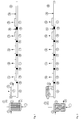
- Fig. 1 the polymer solution is fed through a feed 1 to the tube bundle heat exchanger 2.
- the tube bundle heat exchanger is heated with heating medium, which is supplied at 3 and discharged at 4.
- the pressure in the heat exchanger 2 is maintained with the valve V above the vapor pressure of the solution at heating temperature.
- the polymer solution relaxes via the product distributor 5 and the nozzle plate 6 into the separation vessel 7, which is arranged directly above the extruder.
- the released gas is removed via the vapor line 8.
- the product falls directly into the feed zone 9 of the extruder and is fed through a storage zone 10 to a first degassing zone 11, which has a degassing dome 12. This is followed by further congestion zones 10 and degassing zones 11.
- nitrogen is added via the feed 14 in the kneading zone 12 via the addition point 13.
- additives and optionally melted polymer are added, which are mixed in the pressure build-up and mixing zone 16 with the polymer stream.
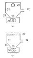
- Fig. 2 the polymer solution is fed through a feed 1 to the tube bundle heat exchanger 2.
- the tube bundle heat exchanger is heated with heating medium, which is supplied at 3 and discharged at 4.
- the pressure in the heat exchanger 2 is maintained with the valve V above the vapor pressure of the solution at heating temperature.
- the polymer solution relaxes via the insertion tube 5 and the openings 6 in the separation vessel 7, which is arranged directly above the extruder.
- the released gas is removed via the vapor line 8.
- the product falls directly into the feed zone 9 of the extruder and is fed through a storage zone 10 to a first degassing zone 11, which has a degassing dome 12. This is followed by further congestion zones 10 and degassing zones 11.
- nitrogen is added via the feed 14 in the kneading zone 12 via the addition point 13.
- addition point 13 are still additives and optionally added molten polymer, which are mixed in the pressure build-up and mixing zone 16 with the polymer stream.
- 3 and 4 show a view of the flash evaporator with separation vessel and underlying extruder shafts in the direction parallel to the axes of the extruder.
- the polycarbonate solution is introduced from above through the flash tube 20 or 20 'into the separator 16.
- the vapors are separated in the separator 21 from the concentrated polymer solution.
- the vapors are fed through the vapor line 22 of the condensation.
- the concentrated polymer solution strikes predominantly directly on the extruder shaft 25 and smaller on the cone 23, from where it flows under the action of gravity to the extruder shaft.
- the extruder shafts are arranged in the upwardly opened extruder housing 24.
- the Yellowness Index YI was determined according to ASTM E 313 on injection molded samples of 4 mm thickness.
- the spraying temperature was 300 ° C.
- the relative viscosity is the ratio of the viscosity of a solution of 0.5 g of polycarbonate in 100 ml of dichloromethane to the viscosity of the pure solvent at 25 ° C.
- 6.5 t / h of polycarbonate were isolated in a device according to the invention from a solution of 65% by weight of polycarbonate, 33.5% by weight of chlorobenzene and 1.5% by weight of methylene chloride.
- the Ausdampffextruder was designed as a close-meshed, co-rotating twin-screw extruder and had a screw diameter of 178 mm, a ratio of length of the extruder to the diameter of 48 and was carried out in the feed zone and the degassing zonesteilteilteil innovation.
- the flash evaporator consisted of a 150 mm diameter pipe slit at the bottom. The inlet temperature into the flash evaporator was 230 ° C. In a Schleppschzone 13 kg / h of nitrogen were supplied.
- the isolated polycarbonate had a relative viscosity of 1.295.
- the residual content of chlorobenzene in the isolated polycarbonate was 330 ppm and the content of dichloromethane was below the detection limit of 0.5 ppm.
- the maximum temperature at the nozzle of the extruder was 391 ° C.
- the yellowness index of the polycarbonate was 1.7.
- 6.5 t / h of polycarbonate were isolated in an extruder with backward degassing from a solution of 65% by weight of polycarbonate, 33.5% by weight of chlorobenzene and 1.5% by weight of methylene chloride.
- the Ausdampffextruder was carried out analogously to the example of the invention as tightly meshing, co-rotating twin-screw extruder and had a screw diameter of 178 mm, a ratio of length of the extruder to the diameter 48 and was carried out in the feed zone and the degassing two-speed.
- 13 kg / h of nitrogen were fed.
- the temperature of the polymer solution from the backward degassing was 185 ° C.
- the entry into the extruder was via a valve.
- the isolated polycarbonate had a relative viscosity of 1.295.
- the residual content of chlorobenzene in the isolated polycarbonate was 410 ppm and the content of dichloromethane was 0.5 ppm.
- the temperature at the die of the extruder was 409 ° C.
- the yellowness index of the polycarbonate was 2.3.
Landscapes
- Chemical & Material Sciences (AREA)
- Chemical Kinetics & Catalysis (AREA)
- Engineering & Computer Science (AREA)
- Mechanical Engineering (AREA)
- Dispersion Chemistry (AREA)
- Health & Medical Sciences (AREA)
- Medicinal Chemistry (AREA)
- Polymers & Plastics (AREA)
- Organic Chemistry (AREA)
- Polyesters Or Polycarbonates (AREA)
- Processes Of Treating Macromolecular Substances (AREA)
- Processing And Handling Of Plastics And Other Materials For Molding In General (AREA)
Priority Applications (8)
| Application Number | Priority Date | Filing Date | Title |
|---|---|---|---|
| EP09007269A EP2255860A1 (de) | 2009-05-30 | 2009-05-30 | Vorrichtung und Verfahren zum Entgasen von lösungsmittelhaltigen Polycarbonatlösungen |
| US13/322,731 US8497345B2 (en) | 2009-05-30 | 2010-03-26 | Device and method for degassing solvent-containing polycarbonate solutions |
| EP10722007.1A EP2435151B1 (de) | 2009-05-30 | 2010-05-26 | Vorrichtung und verfahren zum entgasen von lösungsmittelhaltigen polycarbonatlösungen |
| SG2011080348A SG175850A1 (en) | 2009-05-30 | 2010-05-26 | Device and method for degassing solvent-containing polycarbonate solutions |
| CN201080024023.6A CN102448569B (zh) | 2009-05-30 | 2010-05-26 | 使含溶剂的聚碳酸酯溶液排气的装置和方法 |
| PCT/EP2010/003206 WO2010139413A1 (de) | 2009-05-30 | 2010-05-26 | Vorrichtung und verfahren zum entgasen von lösungsmittelhaltigen polycarbonatlösungen |
| JP2012512253A JP5844253B2 (ja) | 2009-05-30 | 2010-05-26 | 溶媒含有ポリカーボネート溶液を脱気する装置および方法 |
| KR1020117028507A KR101743310B1 (ko) | 2009-05-30 | 2010-05-26 | 용매-함유 폴리카르보네이트 용액의 탈휘발화에 대한 장치 및 방법 |
Applications Claiming Priority (1)
| Application Number | Priority Date | Filing Date | Title |
|---|---|---|---|
| EP09007269A EP2255860A1 (de) | 2009-05-30 | 2009-05-30 | Vorrichtung und Verfahren zum Entgasen von lösungsmittelhaltigen Polycarbonatlösungen |
Publications (1)
| Publication Number | Publication Date |
|---|---|
| EP2255860A1 true EP2255860A1 (de) | 2010-12-01 |
Family
ID=41151757
Family Applications (2)
| Application Number | Title | Priority Date | Filing Date |
|---|---|---|---|
| EP09007269A Withdrawn EP2255860A1 (de) | 2009-05-30 | 2009-05-30 | Vorrichtung und Verfahren zum Entgasen von lösungsmittelhaltigen Polycarbonatlösungen |
| EP10722007.1A Not-in-force EP2435151B1 (de) | 2009-05-30 | 2010-05-26 | Vorrichtung und verfahren zum entgasen von lösungsmittelhaltigen polycarbonatlösungen |
Family Applications After (1)
| Application Number | Title | Priority Date | Filing Date |
|---|---|---|---|
| EP10722007.1A Not-in-force EP2435151B1 (de) | 2009-05-30 | 2010-05-26 | Vorrichtung und verfahren zum entgasen von lösungsmittelhaltigen polycarbonatlösungen |
Country Status (7)
| Country | Link |
|---|---|
| US (1) | US8497345B2 (zh) |
| EP (2) | EP2255860A1 (zh) |
| JP (1) | JP5844253B2 (zh) |
| KR (1) | KR101743310B1 (zh) |
| CN (1) | CN102448569B (zh) |
| SG (1) | SG175850A1 (zh) |
| WO (1) | WO2010139413A1 (zh) |
Cited By (1)
| Publication number | Priority date | Publication date | Assignee | Title |
|---|---|---|---|---|
| WO2022090526A1 (en) | 2020-11-02 | 2022-05-05 | Röhm Gmbh | Device for degassing of a two-component multiphase polymer-monomer material and use thereof in a degassing extruder |
Families Citing this family (7)
| Publication number | Priority date | Publication date | Assignee | Title |
|---|---|---|---|---|
| EP2255859A1 (de) * | 2009-05-30 | 2010-12-01 | Bayer MaterialScience AG | Vorrichtung und Verfahren zum Entgasen von lösungshaltigen Polycarbonatlösungen |
| JP5619239B1 (ja) | 2013-08-27 | 2014-11-05 | 株式会社日本製鋼所 | ベント式二軸混練押出装置及び方法 |
| CN106139626B (zh) * | 2016-08-25 | 2018-05-08 | 山东恒利热载体工程技术有限公司 | 有机热载体在线气提清除裂解轻组分的工艺及装置 |
| EP3933059A1 (en) | 2020-06-29 | 2022-01-05 | Covestro Deutschland AG | Process for the preparation of a polycarbonate |
| CN113694565B (zh) * | 2021-09-02 | 2023-02-21 | 上海盛普流体设备股份有限公司 | 一种具有分段式螺杆与陶瓷衬套的脱泡装置及其脱泡方法 |
| WO2023198550A1 (de) | 2022-04-11 | 2023-10-19 | Covestro Deutschland Ag | Mehrwellige schneckenmaschine mit einem paar schneckenelementen mit verbesserter misch- und entgasungswirkung bei reduziertem energieeintrag |
| CN115260481A (zh) * | 2022-09-05 | 2022-11-01 | 上海华峰新材料研发科技有限公司 | 一种聚合物熔体的脱挥发方法 |
Citations (15)
| Publication number | Priority date | Publication date | Assignee | Title |
|---|---|---|---|---|
| US2964513A (en) * | 1956-08-20 | 1960-12-13 | Phillips Petroleum Co | Polymer recovery process |
| US3450183A (en) * | 1964-10-02 | 1969-06-17 | Phillips Petroleum Co | Polymer recovery apparatus |
| GB1330890A (en) * | 1969-12-24 | 1973-09-19 | Bayer Ag | Process and apparatus for concentrating a solution or suspension |
| DE2908352A1 (de) | 1979-03-03 | 1980-09-18 | Bayer Ag | Verfahren zur getrennten ableitung der einzelnen phasenstroeme einer mehrphasenstroemung |
| EP0027700A2 (en) | 1979-10-09 | 1981-04-29 | Mitsui Petrochemical Industries, Ltd. | Flash-drying process for a solvent solution of a polymer or copolymer |
| EP0359432A2 (en) * | 1988-08-29 | 1990-03-21 | Dainippon Ink And Chemicals, Inc. | Devolatilization of liquid composition containing polymer and volatile constituents |
| JPH0517516B2 (zh) | 1984-06-08 | 1993-03-09 | Hitachi Ltd | |
| US5283021A (en) * | 1993-06-14 | 1994-02-01 | Chi Mei Corporation | Process for removing the solvent from an elastomeric polymer solution |
| EP1113848A1 (de) | 1998-08-07 | 2001-07-11 | Bayer Aktiengesellschaft | Verfahren zum eindampfen von polymerlösungen thermoplastischer polymere |
| DE10016894A1 (de) * | 2000-04-05 | 2001-10-18 | Bayer Ag | Verfahren und Vorrichtung zur Entfernung flüchtiger Bestandteile aus Polymermassen |
| US20010056176A1 (en) * | 2000-06-22 | 2001-12-27 | Jsr Corporation | Method for recovering a polymer |
| EP1165302A1 (de) | 1999-03-27 | 2002-01-02 | Bayer Aktiengesellschaft | Vorrichtung und verfahren zum entgasen von kunststoffen, insbesondere von hochmolekularen polycarbonatlösungen |
| EP1265944A1 (de) | 2000-02-07 | 2002-12-18 | Bayer Aktiengesellschaft | Verfahren zur herstellung von hochreinem polycarbonat und polycarbonat höchster reinheit |
| DE10333577A1 (de) * | 2003-07-24 | 2005-02-24 | Bayer Technology Services Gmbh | Verfahren und Vorrichtung zur Entfernung von flüchtigen Substanzen aus hochviskosen Medien |
| EP1510530A1 (en) | 2003-08-26 | 2005-03-02 | General Electric Company | Method of separating a polymer from a solvent |
Family Cites Families (12)
| Publication number | Priority date | Publication date | Assignee | Title |
|---|---|---|---|---|
| US3458494A (en) | 1964-07-15 | 1969-07-29 | Phillips Petroleum Co | Process for recovering olefin polymers |
| DE2005691A1 (de) | 1970-02-07 | 1971-08-12 | Bayer Ag | Verfahren zur Herstellung selbstver netzbarer hochreaktiver Pulverlackbinde mittel |
| JPS6162522A (ja) * | 1984-09-03 | 1986-03-31 | Daicel Chem Ind Ltd | ポリエステルカーボネートの製法 |
| DE3628994A1 (de) | 1986-08-26 | 1988-03-03 | Basf Ag | Kontinuierliches verfahren zur entfernung von geloesten stoffen aus polymerloesungen |
| JPH0517516A (ja) | 1991-07-10 | 1993-01-26 | Mitsubishi Rayon Co Ltd | 重合体溶液からの揮発物除去方法 |
| US5708133A (en) | 1993-11-09 | 1998-01-13 | Mitsubishi Gas Chemical Company, Inc. | Process for purifying polymer |
| JP4108819B2 (ja) | 1998-03-27 | 2008-06-25 | 新日鐵化学株式会社 | 重合液組成物の脱揮処理方法 |
| DE19817678A1 (de) * | 1998-04-21 | 1999-10-28 | Bayer Ag | Vorrichtung und Verfahren zur Entfernung von flüchtigen Komponenten aus Polymerlösungen |
| JP2002047350A (ja) * | 2000-07-31 | 2002-02-12 | Teijin Chem Ltd | ポリカーボネート樹脂粉粒体の製造方法 |
| DE102008029305A1 (de) | 2008-06-20 | 2009-12-24 | Bayer Technology Services Gmbh | Schneckenelemente mit reduziertem Kammwinkel |
| DE102008029306A1 (de) | 2008-06-20 | 2009-12-24 | Bayer Technology Services Gmbh | Schneckenelemente mit reduziertem Energieeintrag beim Druckaufbau |
| EP2255859A1 (de) * | 2009-05-30 | 2010-12-01 | Bayer MaterialScience AG | Vorrichtung und Verfahren zum Entgasen von lösungshaltigen Polycarbonatlösungen |
-
2009
- 2009-05-30 EP EP09007269A patent/EP2255860A1/de not_active Withdrawn
-
2010
- 2010-03-26 US US13/322,731 patent/US8497345B2/en active Active
- 2010-05-26 CN CN201080024023.6A patent/CN102448569B/zh not_active Expired - Fee Related
- 2010-05-26 SG SG2011080348A patent/SG175850A1/en unknown
- 2010-05-26 EP EP10722007.1A patent/EP2435151B1/de not_active Not-in-force
- 2010-05-26 JP JP2012512253A patent/JP5844253B2/ja not_active Expired - Fee Related
- 2010-05-26 WO PCT/EP2010/003206 patent/WO2010139413A1/de active Application Filing
- 2010-05-26 KR KR1020117028507A patent/KR101743310B1/ko active IP Right Grant
Patent Citations (17)
| Publication number | Priority date | Publication date | Assignee | Title |
|---|---|---|---|---|
| US2964513A (en) * | 1956-08-20 | 1960-12-13 | Phillips Petroleum Co | Polymer recovery process |
| US3450183A (en) * | 1964-10-02 | 1969-06-17 | Phillips Petroleum Co | Polymer recovery apparatus |
| GB1330890A (en) * | 1969-12-24 | 1973-09-19 | Bayer Ag | Process and apparatus for concentrating a solution or suspension |
| DE2908352A1 (de) | 1979-03-03 | 1980-09-18 | Bayer Ag | Verfahren zur getrennten ableitung der einzelnen phasenstroeme einer mehrphasenstroemung |
| EP0027700A2 (en) | 1979-10-09 | 1981-04-29 | Mitsui Petrochemical Industries, Ltd. | Flash-drying process for a solvent solution of a polymer or copolymer |
| US4906329A (en) * | 1979-10-09 | 1990-03-06 | Mitsui Petrochemical Industries, Ltd. | Flash-drying process for a solvent solution of a polymer or copolymer |
| JPH0517516B2 (zh) | 1984-06-08 | 1993-03-09 | Hitachi Ltd | |
| EP0359432A2 (en) * | 1988-08-29 | 1990-03-21 | Dainippon Ink And Chemicals, Inc. | Devolatilization of liquid composition containing polymer and volatile constituents |
| US5283021A (en) * | 1993-06-14 | 1994-02-01 | Chi Mei Corporation | Process for removing the solvent from an elastomeric polymer solution |
| EP1113848A1 (de) | 1998-08-07 | 2001-07-11 | Bayer Aktiengesellschaft | Verfahren zum eindampfen von polymerlösungen thermoplastischer polymere |
| EP1165302A1 (de) | 1999-03-27 | 2002-01-02 | Bayer Aktiengesellschaft | Vorrichtung und verfahren zum entgasen von kunststoffen, insbesondere von hochmolekularen polycarbonatlösungen |
| EP1265944A1 (de) | 2000-02-07 | 2002-12-18 | Bayer Aktiengesellschaft | Verfahren zur herstellung von hochreinem polycarbonat und polycarbonat höchster reinheit |
| DE10016894A1 (de) * | 2000-04-05 | 2001-10-18 | Bayer Ag | Verfahren und Vorrichtung zur Entfernung flüchtiger Bestandteile aus Polymermassen |
| US20010056176A1 (en) * | 2000-06-22 | 2001-12-27 | Jsr Corporation | Method for recovering a polymer |
| DE10333577A1 (de) * | 2003-07-24 | 2005-02-24 | Bayer Technology Services Gmbh | Verfahren und Vorrichtung zur Entfernung von flüchtigen Substanzen aus hochviskosen Medien |
| EP1510530A1 (en) | 2003-08-26 | 2005-03-02 | General Electric Company | Method of separating a polymer from a solvent |
| US20050234219A1 (en) * | 2003-08-26 | 2005-10-20 | Norberto Silvi | Method of separating a polymer from a solvent |
Non-Patent Citations (3)
| Title |
|---|
| "lt Stahlschlüssel", 2007, VERLAG WEGST GMBH |
| KLEMENS KOHLGRÜBER: "Der gleichläufige Doppelschneckenextruder", CARL HANSER VERLAG, pages: 193 - 195 |
| SCHNELL: "Polymer Reviews", vol. 9, 1964, INTERSCIENCE PUBLISHERS, article "Chemistry and Physics of Polycarbonates", pages: 33 - 70 |
Cited By (1)
| Publication number | Priority date | Publication date | Assignee | Title |
|---|---|---|---|---|
| WO2022090526A1 (en) | 2020-11-02 | 2022-05-05 | Röhm Gmbh | Device for degassing of a two-component multiphase polymer-monomer material and use thereof in a degassing extruder |
Also Published As
| Publication number | Publication date |
|---|---|
| KR101743310B1 (ko) | 2017-06-15 |
| JP2012528896A (ja) | 2012-11-15 |
| JP5844253B2 (ja) | 2016-01-13 |
| KR20120036814A (ko) | 2012-04-18 |
| SG175850A1 (en) | 2011-12-29 |
| EP2435151B1 (de) | 2016-05-25 |
| WO2010139413A1 (de) | 2010-12-09 |
| CN102448569A (zh) | 2012-05-09 |
| US8497345B2 (en) | 2013-07-30 |
| EP2435151A1 (de) | 2012-04-04 |
| US20120123084A1 (en) | 2012-05-17 |
| CN102448569B (zh) | 2016-06-01 |
Similar Documents
| Publication | Publication Date | Title |
|---|---|---|
| EP2445950B1 (de) | Polycarbonate mit extrem hoher reinheit und guter eigenfarbe und thermischer beständigkeit sowie eine vorrichtung und ein verfahren zu ihrer herstellung | |
| EP2435151B1 (de) | Vorrichtung und verfahren zum entgasen von lösungsmittelhaltigen polycarbonatlösungen | |
| EP1742983B1 (de) | Verfahren zur herstellung von polycarbonat | |
| EP2435150B1 (de) | Vorrichtung und verfahren zum entgasen von lösungsmittelhaltigen polycarbonatlösungen | |
| EP1740638B1 (de) | Verfahren zur herstellung von polycarbonat | |
| EP0768155B1 (de) | Verfahren zur Herstellung von thermoplastischem Polymergranulat aus Polymerlösungen | |
| EP2098553B1 (de) | Verfahren zur Herstellung von Polycarbonat nach dem Phasengrenzflächenverfahren | |
| EP2255947A1 (de) | Vorrichtung und Verfahren zum Mischen von Polymerschmelzen mit Additiven | |
| DE102008008841A1 (de) | Verfahren zur Herstellung von Polycarbonaten | |
| EP1129123A1 (de) | Reinigung von polycarbonat enthaltenden lösungen | |
| EP2303530B1 (de) | Verfahren zur extrusion plastischer massen | |
| EP3097135B1 (de) | Verfahren zur herstellung von polycarbonat nach dem phasengrenzflächenverfahren | |
| WO2020201180A1 (de) | Verfahren zur herstellung von polycarbonat mit reduziertem phosgenüberschuss | |
| EP3728392B1 (de) | Verfahren zur herstellung von polycarbonat | |
| WO2004035654A1 (de) | Verfahren zur abtrennung von restmonomeren und oligomeren aus polycarbonat | |
| WO2020201179A1 (de) | Verfahren zur herstellung von polycarbonat – zugabezeitpunkt des kettenabbrechers | |
| DE10249270A1 (de) | Rücklöseverfahren |
Legal Events
| Date | Code | Title | Description |
|---|---|---|---|
| PUAI | Public reference made under article 153(3) epc to a published international application that has entered the european phase |
Free format text: ORIGINAL CODE: 0009012 |
|
| AK | Designated contracting states |
Kind code of ref document: A1 Designated state(s): AT BE BG CH CY CZ DE DK EE ES FI FR GB GR HR HU IE IS IT LI LT LU LV MC MK MT NL NO PL PT RO SE SI SK TR |
|
| AX | Request for extension of the european patent |
Extension state: AL BA RS |
|
| 17P | Request for examination filed |
Effective date: 20110601 |
|
| 17Q | First examination report despatched |
Effective date: 20110906 |
|
| STAA | Information on the status of an ep patent application or granted ep patent |
Free format text: STATUS: THE APPLICATION IS DEEMED TO BE WITHDRAWN |
|
| 18D | Application deemed to be withdrawn |
Effective date: 20120117 |