EP2254356A1 - Netzwerksystem und überwachungsknoten - Google Patents
Netzwerksystem und überwachungsknoten Download PDFInfo
- Publication number
- EP2254356A1 EP2254356A1 EP08721660A EP08721660A EP2254356A1 EP 2254356 A1 EP2254356 A1 EP 2254356A1 EP 08721660 A EP08721660 A EP 08721660A EP 08721660 A EP08721660 A EP 08721660A EP 2254356 A1 EP2254356 A1 EP 2254356A1
- Authority
- EP
- European Patent Office
- Prior art keywords
- terminal device
- monitoring node
- wireless
- wireless systems
- terminal
- Prior art date
- Legal status (The legal status is an assumption and is not a legal conclusion. Google has not performed a legal analysis and makes no representation as to the accuracy of the status listed.)
- Withdrawn
Links
- 238000012544 monitoring process Methods 0.000 title claims abstract description 100
- 230000008859 change Effects 0.000 claims description 33
- 230000005540 biological transmission Effects 0.000 claims description 30
- 230000003247 decreasing effect Effects 0.000 claims description 2
- 238000000034 method Methods 0.000 description 74
- 230000008569 process Effects 0.000 description 66
- 238000004891 communication Methods 0.000 description 33
- 230000007423 decrease Effects 0.000 description 8
- 230000001960 triggered effect Effects 0.000 description 8
- 230000001149 cognitive effect Effects 0.000 description 6
- 238000004364 calculation method Methods 0.000 description 4
- 238000010586 diagram Methods 0.000 description 4
- 238000010295 mobile communication Methods 0.000 description 3
- 238000012546 transfer Methods 0.000 description 3
- 230000004044 response Effects 0.000 description 2
- 238000013459 approach Methods 0.000 description 1
- 238000013475 authorization Methods 0.000 description 1
- 230000001413 cellular effect Effects 0.000 description 1
- 238000005516 engineering process Methods 0.000 description 1
- 238000012545 processing Methods 0.000 description 1
- 230000009467 reduction Effects 0.000 description 1
- 238000010187 selection method Methods 0.000 description 1
- 238000004088 simulation Methods 0.000 description 1
- 238000011144 upstream manufacturing Methods 0.000 description 1
Images


Classifications
-
- H—ELECTRICITY
- H04—ELECTRIC COMMUNICATION TECHNIQUE
- H04W—WIRELESS COMMUNICATION NETWORKS
- H04W36/00—Hand-off or reselection arrangements
- H04W36/14—Reselecting a network or an air interface
- H04W36/144—Reselecting a network or an air interface over a different radio air interface technology
- H04W36/1446—Reselecting a network or an air interface over a different radio air interface technology wherein at least one of the networks is unlicensed
-
- H—ELECTRICITY
- H04—ELECTRIC COMMUNICATION TECHNIQUE
- H04W—WIRELESS COMMUNICATION NETWORKS
- H04W36/00—Hand-off or reselection arrangements
- H04W36/24—Reselection being triggered by specific parameters
- H04W36/30—Reselection being triggered by specific parameters by measured or perceived connection quality data
- H04W36/304—Reselection being triggered by specific parameters by measured or perceived connection quality data due to measured or perceived resources with higher communication quality
-
- H—ELECTRICITY
- H04—ELECTRIC COMMUNICATION TECHNIQUE
- H04W—WIRELESS COMMUNICATION NETWORKS
- H04W12/00—Security arrangements; Authentication; Protecting privacy or anonymity
- H04W12/06—Authentication
-
- H—ELECTRICITY
- H04—ELECTRIC COMMUNICATION TECHNIQUE
- H04W—WIRELESS COMMUNICATION NETWORKS
- H04W12/00—Security arrangements; Authentication; Protecting privacy or anonymity
- H04W12/60—Context-dependent security
- H04W12/61—Time-dependent
Definitions
- This invention relates to a technique of changing wireless communication systems at higher speed, and cognitive radio technology for improving the time use efficiency of frequency.
- the frequency band below 6 GHz (the VHF, UHF, and low microwave bands) convenient for mobile communication systems is now used densely by the third generation mobile phones, wireless LANs, and others, so conditions of radio waves are seriously tight.
- a technique is required that accomplishes advanced sharing of radio waves among a plurality of radio wave application systems including the mobile communications.
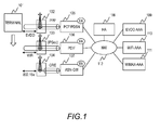
- FIG. 1 illustrates an entire configuration of a conventional system with a plurality of wireless systems connected.
- three systems are connected: cdma 1xEVDO (1xEVolution Data Only) as a cellular system, WiMAX as an outdoor wireless broadband system in an urban area, and a wireless LAN (Local Area Network) as a close-range or indoor broadband system.
- cdma 1xEVDO (1xEVolution Data Only)
- WiMAX as an outdoor wireless broadband system in an urban area
- a wireless LAN Local Area Network
- the system comprises a terminal (101) applicable to communications in these plurality of wireless systems, access points in those wireless systems ((102) for EVDO, (103) for the wireless LAN, and (104) for WiMAX), gateways for terminating the wireless systems (corresponding to a PDSN (Packet Data Serving Node) (105) for EVDO, a PDIF (Packet Data Interworking Function) (106) for the wireless LAN, and an ASN-GW (Access Service Network GateWay) (107) for WiMAX), certificate authorities for user authentications in the systems (corresponding to an EVDO-AAA (Authentication Authorization Accounting) (109) for EVDO, a WiFi-AAA (110) for the wireless LAN, and a WiMAX-AAA (111) for WiMAX), and an HA (Home Agent) (108).
- the gateways, the HA, and the certificate authorities which terminate each system are interconnected by a network (112).
- the access points (102, 103, 104) in the wireless systems each have a function to terminate the wireless zone to the terminal.
- the gateways like the PDSN, PDIF, and ASN-GW each have a function of FA (Foreign Agent) to the HA and a function to terminate the wireless system.
- FA Form Agent
- an access point is connected with a gateway in each wireless system in FIG. 1
- the number of access points is not limited to one but a plurality of access points are usually connected with each gateway.
- the systems are independently operated, so the certificate authorities (109, 110, 111) exist independently and user authentications are performed independently in the use of the respective wireless systems.
- the HA (108) manages which wireless system the terminal is currently using in the communication. Specifically, when viewed from the HA, the PDSN (105) behaves as a FA in EVDO, the PDIF (106) behaves as a FA in the wireless LAN, and the ASN-GW (107) behaves as a FA in WiMAX, and the HA has a table containing correspondence relations between the IP address of the gateway in the wireless system used in the current communication and the IP addresses given to the terminal.
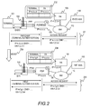
- FIG. 2 illustrates a method of obtaining an IP address assigned to a terminal, a flow of changing the wireless system in use because of, for example, a transfer of the terminal, and the relationship between the IP addresses of gateways and the IP addresses of the terminal in a conventional example.
- a terminal authentication called PAP/ CHAP is performed between the terminal (101) and the PDSN (105) of the EVDO gateway as shown in the procedure (201).
- the PDSN After the PDSN has authenticated the terminal, it sends an Access Request from the terminal (101) to the EVDO-AAA (109).
- the HA's IP 1.2.3.4) to the PDSN (105) as a response to the Access Request, and the PDSN (105) transfers the information to the terminal (101) to assign the IP address to the terminal.
- this terminal moves (205) and newly connects to, for example, the wireless LAN system, which is different from EVDO, a terminal authentication called IKEv2 is performed between the terminal and the PDIF (106) of the wireless LAN gateway as shown in the procedure (203).
- the PDIF After the PDIF has authenticated the terminal, it sends an Access Request from the terminal (101) to the WiFi-AAA (110).
- the HA's IP 1.2.3.4) to the PDIF (106) as a response to the Access Request, and the PDIF (106) transfers the information to the terminal (101) to assign the IP address to the terminal.
- FIG. 3 illustrates such a situation.
- the HA is in a handover situation with respect to the terminal (101), where data are transmitted from the both gateways, so the two PDIFs (106 and 304) are registered as FAs (302).
- the data from a communication party on the network side is multicasted to both of the PDIF (106) and PDIF (304), with reference to the HA.
- the HA can have a plurality of FA addresses for a single terminal IP within the same system in the conventional system, data are multicasted to the FAs in such a situation. Furthermore, a change of gateways take time in the order of seconds because a user authentication is performed at every gateway.
- a representative aspect of this invention calculates, before a terminal newly connects to a wireless system or changes the wireless system into another, an expected throughput in the whole system and expected delay time in the case that the terminal connects to the wireless system, and controls the wireless system to be connected from the terminal depending on the estimation.
- a representative aspect of this invention monitors the throughput and the delay time of each terminal, and if the quality of communication is degraded, for example, if the throughput decreases or the delay time increases, it predicts whether or not the quality of communication will be improved by changing the wireless system, and selects the wireless system to be used by the terminal in accordance with the results of the prediction.
- an appropriate wireless system can be assigned to each terminal by considering radio environments for all terminals connecting to the system, so that the throughput in the whole system can improve.
- a first embodiment of this invention will be described.
- the wireless system to be connected from the terminal is determined so as to maximize the system throughput.
- FIG. 4 illustrates a configuration of a system in this invention.
- the system comprises a monitoring node (CMT: Cognitive Monitoring Tool) (404) which collects information about radio from an access point in each wireless system.
- the information about radio includes received power values, RSSI values, throughputs of users, transmission rate, transmission delay time, packet loss rate, the number of terminals accommodated in an access point, the number of associations with a terminal, processing load at an access point.
- CMT Cognitive Monitoring Tool
- the monitoring node has information about application programs to be used by users, such as TOS values in an IP header and a communication port number used by an application program.
- Such information is statistically processed in the monitoring node, and further, space information such as the terminal's position and the moving direction is taken into account, to determine the wireless system to be assigned to each terminal.
- the system further comprises a control node (PSF: Packet Switching Function) (405) between the upstream side of gateways (105, 106, 107) of the respective wireless systems and a network (112) for switching packets in accordance with instructions from the monitoring node (404).
- PSF Packet Switching Function
- the system comprises a certificate authority (403) common to a plurality of wireless systems for assigning the same IP address to a terminal applicable to a plurality of wireless systems across the plurality of systems.
- FIG. 4 exemplifies three wireless systems to be used, EVDO, WiMAX, and WiFi (wireless LAN), but they may be other existing wireless systems or next generation wireless systems which will be developed in the future.
- the number of wireless systems to be used may be more than three.
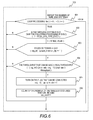
- FIG. 5 illustrates a wireless system determination process by the monitoring node.
- the process is triggered when a terminal tries to change the wireless system into another one.
- another terminal's try to start connecting to the system may be the trigger of the wireless system determination process.
- the trigger may be when another wireless system becomes available for use or when the wireless system in use by an existing terminal becomes unavailable for use, because of moving of the terminal connecting to the wireless system.
- the trigger may be when a communication starts because of a user's newly executing an application program or when a communication ends by ending the execution of an application program.
- the process may be performed periodically in all of the terminals in the system.
- the monitoring node first initializes the threshold value of received power for determining the availability of communication in each wireless system, the maximum throughput available in each wireless system, and others (501). Next, it counts the terminals currently connecting to the system, except for the terminal (subject terminal) which triggered the process (502). Then, it calculates the throughput currently available in the unused bandwidth by excluding the throughput in the bandwidth actually occupied by the terminals except for the subject terminal from the maximum throughput (503). It compares the received power by the subject terminal with the threshold value determined at the initialization in each wireless system, and, if the received power exceeds the threshold value, it sets a flag (504).
- the monitoring node counts wireless systems connectable from the subject terminal (505), selects the system to be connected from the subject terminal (506), and determines the wireless system (the determined system) to be used by the subject terminal.
- the monitoring node which has determined the wireless system to be used by the subject terminal instructs the control node to communicate with the subject terminal in the determined system, and the control node changes the wireless system used in the communication with the subject terminal in accordance with the instruction from the monitoring node.
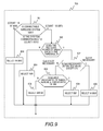
- FIG. 6 illustrates the process of counting wireless systems connectable from the subject terminal in FIG. 5 (505) in detail.
- the process of counting wireless systems connectable from the subject terminal is repeated by the number of wireless systems available in the system (601).
- the selected system is EVDO that covers the whole area of movement
- the monitoring node determines that the terminal can be reached wherever it is, and skips the following processes (602).
- EVDO is exemplified as a wireless system that can cover the whole area within which the terminal may move, but if there exist any other wireless systems that can cover the whole area of movement, the monitoring node may skip the process to those wireless systems.
- the monitoring node checks whether a flag indicating that the received power in the selected wireless system exceeds the threshold value has been set or not (603). If the flag indicating that the received power in the selected wireless system exceeds the threshold value has not been set, connection to the wireless system is not available, so the monitoring node proceeds to the determination on the next wireless system. If the flag has been set, it compares the throughput required by the subject terminal with the throughput available in the unused bandwidth in the system calculated in the step 503 (604). If the throughput available in the unused bandwidth exceeds the throughput required by the terminal, the monitoring node turns ON a flag indicating that the wireless system is connectable (605), and increments the number of connectable systems. The monitoring node performs these steps in all of the wireless systems within the system.
- the monitoring node executes a process of selecting the wireless system to be connected from the subject terminal (701 in FIG. 7 ), depending on the number of connectable wireless systems obtained in the process of counting wireless systems connectable from the subject terminal.
- FIG. 8 illustrates the wireless system selection process in the case that the number of connectable wireless systems is 0 (702).
- the process determines the system with a priority to the wireless system that satisfies the threshold criterion of the received power.
- the monitoring node checks whether the received power in WiMAX exceeds the threshold value (801). If it does not exceed the threshold value, the monitoring node checks whether the received power in WiFi exceeds the threshold value (802).
- the connectable wireless system is EVDO only, so the monitoring node selects EVDO as the system to be connected (803). If the received power in WiFi exceeds the threshold value, it selects WiFi as the system to be connected (804).
- the monitoring node checks the received power in WiFi (805). If it does not exceed the threshold value, the monitoring node selects WiMAX as the system to be connected (806). If it exceeds the threshold value, the monitoring node checks whether the QoS is necessary for the communication requested by the user or not (807). In this embodiment, the monitoring node refers to the value in the TOS field in an IP packet to determine the necessity of QoS; if the TOS value is 0, the monitoring node determines that the QoS is not necessary. The necessity of QoS may be determined by referring to the port number to be used in the communication and a prepared relation table between port numbers and the necessity of the QoS.
- the monitoring node compares the throughput available in the unused bandwidth in WiMAX with that in WiFi (808), and if the throughput available in the unused bandwidth in WiMAX is greater than that in WiMAX, it selects WiMAX as the system to be connected (806). Otherwise, it selects WiFi (804). If QoS is needed, it selects WiMAX (806).
- the selection is made between WiMAX which can guarantee the QoS and WiFi which cannot guarantee the QoS.
- the monitoring node selects the wireless system whose available throughput in the unused bandwidth is great.
- priority orders may be placed to the wireless systems which can guarantee the QoS depending on the quality of guarantee, and further, depending on the quality of communication required by application programs, and then, the monitoring node may select the wireless system to be connected depending on the association of the priorities. It is the same in the case that there are a plurality of wireless systems that cannot guarantee the QoS.
- FIG. 9 illustrates the process of selecting a wireless system in the case that the number of connectable wireless system is one (703).
- the monitoring node determines which the connectable wireless system is, WiMAX or WiFi (901). If the connectable wireless system is WiMAX, it selects WiMAX because it can be determined that the QoS is guaranteed and the unused bandwidth is sufficient.
- the monitoring node subsequently checks whether the received power in WiMAX exceeds the threshold value or not (902). If the received power in WiMAX does not exceed the threshold value, it selects WiFi as the wireless system to be connected. If the received power in WiMAX exceeds the threshold value, the operations following to this step is the same as the process explained with reference to FIG. 8 . Therefore, those steps are denoted by the same reference numerals as in FIG. 8 and the explanations will be omitted.
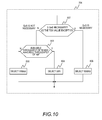
- FIG. 10 illustrates the process of selecting a wireless system in the case that the number of connectable wireless system is two (704).
- the flow of the process is the same as a part of the process illustrated in FIG. 8 , so the steps are denoted by the same reference numerals as in FIG. 8 and the explanations will be omitted.
- an estimated throughput after the change of the wireless systems is preliminarily calculated. Accordingly, the wireless system to be connected from the terminal can be selected on the basis of the calculated results so that the system throughput will be the maximum.
- the system to be connected from the terminal is determined so that the delay time will be the minimum.
- this embodiment employs the system configuration shown in FIG. 4 .
- a wireless system determination process when a terminal AT0 tries to change the connected system from WiMAX to another system will be described.
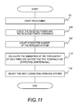
- FIG. 11 illustrates a wireless system determination process by the monitoring node.
- the wireless system determination process is triggered when the terminal AT0 tries to change the currently connected WiMAX into another wireless system.
- another terminal's try to start connecting to the system may be the trigger of the wireless system determination process.
- the trigger may be when another wireless system becomes available for use or when the wireless system in use by an existing terminal becomes unavailable for use, because of moving of the terminal currently connecting to the wireless system.
- the trigger may be when a communication starts because of a user's newly executing an application program or when a communication ends by ending the execution of an application program.
- the process may be performed periodically in all of the terminals in the system.
- the monitoring node first initializes the threshold value of received power for determining the availability of communication in each wireless system, the maximum throughput in each wireless system, and others (501). Next, it compares the received power by the subject terminal with the threshold value determined at the initialization in each wireless system, and, if the received power exceeds the threshold value, it sets a flag (504). It counts the terminals currently connecting to the system, except for the terminal (subject terminal) which triggered the process (502).
- the monitoring node calculates the sum of the throughputs of the terminals except for the subject terminal (ATO) in each wireless system (1101). For example, if the monitoring node has a table (1201), like the one shown in FIG. 12 , that associates the wireless system (1203) currently connected from each terminal and the throughput (1204) of each terminal, the throughput in WiMAX is the sum of the throughputs of AT1 and AT3, which are currently connected to WiMAX, 4.2 Mbps, and the throughput in WiFi is the throughput of AT2 which is currently connected to WiFi, 28.8 Mbps.
- the monitoring node performs a selection process of the system to be connected from the subject terminal (1102) to determine the wireless system (the determined system) to be used by the subject terminal.
- the monitoring node that has determined the wireless system to be used by the subject terminal instructs the control node to communicate with the subject terminal in the determined system, and the control node changes the wireless system to be used in the communication with the subject terminal in accordance with the instruction from the monitoring node.
- FIG. 13 illustrates the wireless system selection process (1102) in detail.
- the monitoring node checks whether the received power in WiMAX exceeds the threshold value or not (1301). If it does not exceed the threshold value, the monitoring node checks whether the received power in WiFi exceeds the threshold value (1302). If the received power in WiFi does not exceed the threshold value, either, the wireless system that can be connected is EVDO only, so the monitoring node selects EVDO as the system to be connected (803). If the received power in WiFi exceeds the threshold value, it selects WiFi as the system to be connected (804).
- the monitoring node checks the received power in WiFi (1303). If it does not exceed its threshold value, the monitoring node selects WiMAX as the system to be connected (806). If it exceeds the threshold value, the monitoring node calculates the transmission delay time in the case that the subject terminal is connected to WiFi (1304) and the transmission delay time in the case that the subject terminal keeps connection to WiMAX (1305). Then, it compares the expected transmission delay time obtained in the step of (1304) and the one obtained in the step (1305) (1306), and selects the wireless system with shorter delay time to determine the wireless system to be connected from the subject terminal.
- FIG. 14 provides tables storing the correspondence relations of the throughputs (1402, 1405) and the delay time (1403, 1406) to be used in estimating the transmission delay time.
- These tables are delay time tables (1401, 1404) corresponding to the throughputs in WiMAX and WiFi, respectively, except for in EVDO, which is always connectable.
- the information in these tables is preliminarily measured values or estimated values obtained through simulations, for example.
- FIG. 15 illustrates a delay time calculation process in WiFi (1304) in detail.
- the monitoring node adds the throughput of the subject terminal (ATO) to the throughput in WiFi obtained in the step (1101) of FIG. 11 , and compares the sum with the maximum throughput in WiFi (1501). If the total throughput of the terminals is less than the maximum throughput in WiFi, the monitoring node obtains the delay time from the table of delay time corresponding to throughputs in WiFi (1502) using the throughput of AT0 as a key.
- the monitoring node obtains the delay time from the table of delay time corresponding to throughputs in WiFi (1502) using the throughput of AT0 as a key, and then determines the delay time in WiFi by multiplying the obtained delay time by the number of terminals to be connected to WiFi (where the subject terminal should be included, assuming that the subject terminal is connecting) (1503).
- the delay time in WiFi is the value obtained by multiplying the delay time (6.728E-03), which is obtained from the table of delay time corresponding to throughputs in WiFi using 4.8 Mbps of AT0's throughput as a key, by the number of connecting terminals of 2 (existing AT2 connecting to WiFi and ATO).
- FIG. 16 illustrates a delay time calculation process in WiMAX (1305) in detail. First, it adds the throughput of the subject terminal (ATO) to the throughput in WiMax obtained in the step (1101) in FIG. 11 , and compares the sum with the maximum throughput in WiMAX (1601). If the total throughput of the terminal is less than the maximum throughput in WiMAX, it obtains the delay value from the table of throughputs vs. delay time in WiMAX (1602) using the throughput of AT0 as a key.
- the monitoring node obtains the delay time from the table of delay time corresponding to throughputs in WiMAX (1602) using the throughput of AT0 as a key, and then determines the delay time in WiMAX by multiplying the obtained delay time by the number of terminals to be connected to WiMAX (where the subject terminal should be included, assuming that the subject terminal is connecting) (1603).
- the delay time in WiMAX is the value obtained by multiplying the delay time (3.889E-02), which is obtained from the table of delay time corresponding to throughputs in WiMAX using 4.8 Mbps of AT0's throughput as a key, by the number of connecting terminals of 3 (existing AT1 and AT3 connecting to WiMAX and ATO).
- the estimated delay time in the case that it connects to WiFi is shorter. Therefore, WiFi is selected as the wireless system to be connected from the terminal AT0. Since the wireless system connected from the AT0 has been WiMAX, a change of the wireless system occurs, from WiMAX to WiFi.
- an estimated delay time after the change of wireless systems can be preliminarily calculated. Accordingly, the wireless system to be connected from the terminal can be selected so that the delay time will be the minimum.
- the monitoring node selects the wireless system to be connected from the terminal with the target values of the maximum throughput in the whole system and the shortest transmission delay time.
- the monitoring node may selects the wireless system to be connected from the terminal with the target values of the maximum satisfaction (guarantee) level in the user's QoS in the whole system and the minimum fluctuation in transmission time in the whole system.
- the monitoring node periodically monitors the throughput of each terminal, and if it detects a decrease in the throughput, it determines whether to change the wireless system to accomplish efficient use of communication bandwidth in the whole system.
- this embodiment employs the system configuration shown in FIG. 4 .
- the monitoring node periodically measures the throughputs of all of the terminals currently connecting to the system to determine whether to change the wireless system in each terminal.
- FIG. 17 illustrates a process of determining the change of the wireless system by the monitoring node.
- the monitoring node initializes the threshold value of received power and the maximum throughput in each wireless system (1701). Then, it checks whether the received power by the terminal which is subjected to the wireless system change determination process exceeds the threshold value in each wireless system, and, if the received power exceeds the threshold value, it sets a flag (504).
- the monitoring node that has determined the wireless system to be used by the subject terminal instructs the control node to communicate with the subject terminal in the determined system, and the control node changes the wireless system to be used in the communication with the subject terminal in accordance with the instruction from the monitoring node. If the determined system is the wireless system which has been connected from the subject terminal, the monitoring node does not instruct the change of the wireless system to the control node.
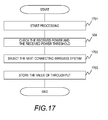
- FIG. 18 illustrates the wireless system selection process (1702) according to this embodiment in detail.
- the monitoring node checks whether the received power in WiMAX exceeds the threshold value or not (1801). If it does not exceed the threshold value, the monitoring node checks whether the received power in WiFi exceeds the threshold value (1802). If the received power in WiFi does not exceed the threshold value, either, the connectable wireless system is EVDO only, so the monitoring node selects EVDO as the system to be connected (803). If the received power in WiFi exceeds the threshold value, it selects WiFi as the system to be connected (804).
- the monitoring node checks the received power in WiFi (1803). If it does not exceed its threshold value, the monitoring node selects WiMAX as the system to be connected (806). If it exceeds the threshold value, the monitoring node obtains the throughput of the subject terminal at present (current throughput) and compares it with the throughput of the subject terminal previously stored (previous throughput) (1804). If there is no decrease from the previous throughput to the current throughput, it checks whether the wireless system currently connected from the subject terminal is EVDO or not (1805). If the current wireless system connected from the subject terminal is not EVDO, it keeps the current system and does not change the wireless system (1806). If the current system is EVDO, it selects WiFi as the wireless system to be connected from the subject terminal.
- the monitoring node changes systems. To prevent frequent changes of wireless systems because of slight variations in the throughput, the monitoring node does not determine that the throughput has decreased if the decrease is within a predetermined range.
- the predetermined range is the variation in the throughput within 3%, for example.
- the monitoring node checks the current system connected from the subject terminal (1807), and if the current system is WiMAX, it selects WiFi. If the current system is WiFi, it selects WiMAX. If EVDO, it selects WiFi. In this embodiment, the monitoring node selects the wireless system to be connected so as to make communication as fast as possible. However, it may select the wireless system in view of the quality of communication which is required by a user application program, instead of the transmission speed.
- the monitoring node periodically monitors the throughput of each terminal, and, if it detects a decrease in the throughput, it determines whether to change the wireless system. Thereby, the communication bandwidth in the whole system can be used efficiently.
- the monitoring node periodically monitors the transmission delay time of each terminal, and if it has detected an increase in the transmission delay time, it determines whether to change the wireless system to accomplish the minimum transmission delay time in the whole system.
- this embodiment employs he system configuration shown in FIG. 4 .
- the monitoring node periodically measures the transmission delay time of all of the terminals currently connecting to the system to determine whether to change the wireless system in each terminal.
- FIG. 19 illustrates a process of determining the change of the wireless system by the monitoring node.
- the monitoring node initializes the threshold value of received power and the maximum throughput in each wireless system (1701). Then, it checks whether the received power by the terminal which is subjected to the wireless system change determination process exceeds the threshold value in each wireless system, and, if the received power exceeds the threshold value, it sets a flag (504).
- the monitoring node that has determined the wireless system to be used by the subject terminal instructs the control node to communicate with the subject terminal in the determined system, and the control node changes the wireless system to be used in the communication with the subject terminal in accordance with the instruction from the monitoring node. If the determined system is the wireless system which has been connected from the subject terminal, the monitoring node does not instruct the change of the wireless system to the control node.
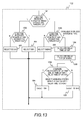
- FIG. 20 illustrates the wireless system selection process (1901) according to the present embodiment in detail.
- a part of the steps in the process shown in FIG. 20 are the same as those in the processes illustrated in FIG. 8 and FIG. 18 ; they are denoted by the same reference numerals.
- the difference in FIG. 20 from FIG. 8 and FIG. 18 is comparing the previous delay time with the current delay time in (2001) to determine the wireless system to be connected from the subject terminal depending on whether the delay time has increased or not.
- the monitoring node does not determine that the delay time has increased if the increase is within a predetermined range.
- the predetermined range is the variation in the delay time within 2%, for example.
- the monitoring node periodically monitors the delay time of each terminal, and, if it has detected an increase in the delay time, it determines whether to change the wireless system. Thereby, the transmission delay time in the whole system can be minimized.
- throughputs and delay time are employed as indexes to determine whether to change the wireless system.
- packet loss rate if the packet loss rate has become higher, the determination whether to change the wireless systems is performed
- number of terminals connecting to the wireless systems and the number of associations if the number of terminals connecting to the wireless systems and the number of associations increase, the determination whether to change the wireless systems is performed
- the like may be used as indexes.
- the wireless system selection methods have been described in the case that the number of indexes is one in determining whether to change the systems.
- the wireless system to be connected from a terminal may be determined by referring to the combination of two or more indexes. For example, throughputs and delay time may be combined to improve the throughput in the whole system and the wireless system with the shortest transmission delay time may be selected.
- throughputs, transmission delay time, packet loss rate, the number of terminals currently connecting to the wireless systems and the number of associations, and the quality requested by a user application program, and the like may be the indexes to be combined.
- This invention is applicable to a system that is operated as a system using a plurality of wireless systems such as mobile phones and wireless LANs simultaneously and aims to improve time use efficiency of frequency and to disperse the loads of wireless systems.
Landscapes
- Engineering & Computer Science (AREA)
- Computer Networks & Wireless Communication (AREA)
- Signal Processing (AREA)
- Mobile Radio Communication Systems (AREA)
Applications Claiming Priority (1)
| Application Number | Priority Date | Filing Date | Title |
|---|---|---|---|
| PCT/JP2008/054244 WO2009110103A1 (ja) | 2008-03-04 | 2008-03-04 | ネットワークシステム及び監視ノード |
Publications (1)
| Publication Number | Publication Date |
|---|---|
| EP2254356A1 true EP2254356A1 (de) | 2010-11-24 |
Family
ID=41055681
Family Applications (1)
| Application Number | Title | Priority Date | Filing Date |
|---|---|---|---|
| EP08721660A Withdrawn EP2254356A1 (de) | 2008-03-04 | 2008-03-04 | Netzwerksystem und überwachungsknoten |
Country Status (4)
| Country | Link |
|---|---|
| US (1) | US20110007651A1 (de) |
| EP (1) | EP2254356A1 (de) |
| JP (1) | JP5031887B2 (de) |
| WO (1) | WO2009110103A1 (de) |
Cited By (2)
| Publication number | Priority date | Publication date | Assignee | Title |
|---|---|---|---|---|
| WO2013135293A1 (en) * | 2012-03-15 | 2013-09-19 | Nokia Siemens Networks Oy | Apparatus and method for handover between different carrier networks |
| CN106488557A (zh) * | 2016-10-28 | 2017-03-08 | 中国人民解放军信息工程大学 | 基于WiFi信号的LDCC‑PDF分级时延估计方法 |
Families Citing this family (19)
| Publication number | Priority date | Publication date | Assignee | Title |
|---|---|---|---|---|
| US8284660B2 (en) * | 2009-10-30 | 2012-10-09 | Qualcomm, Incorporated | Method and apparatus for scheduling of quality of service (QoS) transmissions in a wireless communication system |
| JP5421740B2 (ja) * | 2009-11-19 | 2014-02-19 | 株式会社Nttドコモ | 無線通信装置および無線通信方法 |
| US9238324B2 (en) | 2010-03-31 | 2016-01-19 | Toray Plastics (Amercia), Inc. | Biaxially oriented polylactic acid film with reduced noise level |
| JP5414619B2 (ja) * | 2010-05-21 | 2014-02-12 | 株式会社日立製作所 | 複数無線システムの体感品質向上制御を行う無線通信システム,アクセスポイント,ゲートウェイ |
| US8509802B2 (en) * | 2010-05-26 | 2013-08-13 | Qualcomm Incorporated | Methods and apparatus supporting load balancing in a wireless communications system |
| JP5459147B2 (ja) * | 2010-08-30 | 2014-04-02 | トヨタ自動車株式会社 | コグニティブ無線システム、コグニティブ無線端末、およびハンドオーバー制御方法 |
| CN102547717B (zh) | 2010-12-09 | 2016-06-15 | 中兴通讯股份有限公司 | 认知无线电系统工作模式转换方法及装置 |
| JP5670937B2 (ja) * | 2012-02-28 | 2015-02-18 | 日本電信電話株式会社 | 端末接続管理システム |
| JP5959360B2 (ja) * | 2012-07-26 | 2016-08-02 | 京セラ株式会社 | 無線通信端末、方法、プログラム |
| MY177463A (en) * | 2012-12-13 | 2020-09-16 | Mimos Berhad | System and method for selecting a network connectivity |
| JP5783995B2 (ja) * | 2012-12-27 | 2015-09-24 | 株式会社日立製作所 | 無線端末、管理サーバ及びそれらを用いた無線通信システム |
| JP6048283B2 (ja) * | 2013-03-29 | 2016-12-21 | 富士通株式会社 | 基地局、制御方法および通信システム |
| JP6654937B2 (ja) * | 2016-03-11 | 2020-02-26 | 株式会社Nttドコモ | 通信装置 |
| JP6676453B2 (ja) * | 2016-04-20 | 2020-04-08 | 株式会社Nttドコモ | 情報処理装置 |
| JP7145094B2 (ja) * | 2019-02-05 | 2022-09-30 | Kddi株式会社 | 制御装置、コンピュータプログラム及び情報処理方法 |
| JP7206487B2 (ja) * | 2019-02-21 | 2023-01-18 | 富士通株式会社 | ネットワーク制御装置、及び制御方法 |
| WO2021038863A1 (ja) * | 2019-08-30 | 2021-03-04 | ソニー株式会社 | 判定装置、判定方法および判定プログラム |
| JP2021158486A (ja) * | 2020-03-26 | 2021-10-07 | ソニーグループ株式会社 | 制御装置、無線通信装置および制御方法 |
| JP2024066150A (ja) * | 2022-11-01 | 2024-05-15 | 株式会社日立製作所 | 通信システム、通信装置、及び通信方法 |
Family Cites Families (15)
| Publication number | Priority date | Publication date | Assignee | Title |
|---|---|---|---|---|
| JP4161782B2 (ja) * | 2002-04-18 | 2008-10-08 | 松下電器産業株式会社 | モバイルノードおよび移動通信方法 |
| JP4496733B2 (ja) * | 2003-08-06 | 2010-07-07 | 日本電気株式会社 | 移動通信システム及びそれに用いるハンドオーバ方法 |
| JP4185853B2 (ja) * | 2003-11-28 | 2008-11-26 | 株式会社日立コミュニケーションテクノロジー | 無線システム、サーバ、および移動局 |
| JP4196801B2 (ja) * | 2003-10-01 | 2008-12-17 | 株式会社日立製作所 | 無線システムおよび移動局 |
| ATE446627T1 (de) * | 2003-12-01 | 2009-11-15 | Ericsson Telefon Ab L M | Verkehrsregelverfahren |
| JP2005244525A (ja) * | 2004-02-25 | 2005-09-08 | Fujitsu Ltd | 通信装置 |
| JP4427415B2 (ja) * | 2004-08-05 | 2010-03-10 | 株式会社日立コミュニケーションテクノロジー | ハンドオフ制御方法、無線制御局及び無線基地局 |
| US7502617B2 (en) * | 2004-09-02 | 2009-03-10 | Cisco Technology, Inc. | Rapid search for optimal wireless network configuration |
| JP2006222822A (ja) * | 2005-02-14 | 2006-08-24 | Hitachi Ltd | ハンドオーバシステム |
| CN1953607B (zh) * | 2005-10-17 | 2012-01-25 | 株式会社日立制作所 | 移动网络通信中切换的方法和设备 |
| US7363037B2 (en) * | 2005-10-26 | 2008-04-22 | National Chiao Tung University | Vertical handover control algorithm for WLAN and UMTS |
| JP4050295B2 (ja) * | 2005-11-10 | 2008-02-20 | 株式会社東芝 | 通信システム、移動通信端末装置及び制御局 |
| US8121607B2 (en) * | 2006-11-27 | 2012-02-21 | Zte (Usa) Inc. | Mobile station initiated load balancing in wireless communication networks |
| US8145210B2 (en) * | 2006-12-29 | 2012-03-27 | United States Cellular Corporation | Enhanced cross-network handoff for mobile IP service mobility |
| US7899451B2 (en) * | 2007-07-20 | 2011-03-01 | Jianhong Hu | OWA converged network access architecture and method |
-
2008
- 2008-03-04 JP JP2010501753A patent/JP5031887B2/ja not_active Expired - Fee Related
- 2008-03-04 US US12/867,393 patent/US20110007651A1/en not_active Abandoned
- 2008-03-04 EP EP08721660A patent/EP2254356A1/de not_active Withdrawn
- 2008-03-04 WO PCT/JP2008/054244 patent/WO2009110103A1/ja active Application Filing
Non-Patent Citations (1)
| Title |
|---|
| See references of WO2009110103A1 * |
Cited By (3)
| Publication number | Priority date | Publication date | Assignee | Title |
|---|---|---|---|---|
| WO2013135293A1 (en) * | 2012-03-15 | 2013-09-19 | Nokia Siemens Networks Oy | Apparatus and method for handover between different carrier networks |
| CN106488557A (zh) * | 2016-10-28 | 2017-03-08 | 中国人民解放军信息工程大学 | 基于WiFi信号的LDCC‑PDF分级时延估计方法 |
| CN106488557B (zh) * | 2016-10-28 | 2019-05-03 | 中国人民解放军信息工程大学 | 基于WiFi信号的LDCC-PDF分级时延估计方法 |
Also Published As
| Publication number | Publication date |
|---|---|
| WO2009110103A1 (ja) | 2009-09-11 |
| US20110007651A1 (en) | 2011-01-13 |
| JPWO2009110103A1 (ja) | 2011-07-14 |
| JP5031887B2 (ja) | 2012-09-26 |
Similar Documents
| Publication | Publication Date | Title |
|---|---|---|
| EP2254356A1 (de) | Netzwerksystem und überwachungsknoten | |
| Malik et al. | QoS in IEEE 802.11-based wireless networks: A contemporary review | |
| EP2051452B1 (de) | Kommunikationssystem mit mehrfach-funkmodus | |
| US20170111854A1 (en) | Quality of service aware access point and device steering | |
| Zhu et al. | Optimizations for vertical handoff decision algorithms | |
| Sgora et al. | Handoff prioritization and decision schemes in wireless cellular networks: a survey | |
| EP1641296B1 (de) | Vorrichtung and Verfahren für Zuweisung eines Frequenzbandes | |
| EP1844575B1 (de) | Verfahren und system zur schätzung der anzahl zusätzlich erlaubter anrufe zur verwendung bei der rufzulassungssteuerung | |
| EP1641186B1 (de) | Vorrichtung und Verfahren zur Frequenzband-Zuweisung | |
| EP2314094B1 (de) | Systeme und verfahren zur verringerung von störungen zwischen einer makrobasisstation und einer femtobasisstation | |
| JP5898331B2 (ja) | マルチチャネル無線通信システム、基地局、チャネル利用方法 | |
| US20060063533A1 (en) | Frequency band allocation device and method | |
| US8219131B2 (en) | Cognitive wireless communication system | |
| KR20020077899A (ko) | 이동 통신 네트웍의 핸드오버 제어 방법 | |
| Goyal et al. | On the packet allocation of multi-band aggregation wireless networks | |
| US20140349650A1 (en) | Temporarily Serving a User Equipment by a Second Cell | |
| Jorgensen et al. | On the potentials of traffic steering techniques between HSDPA and LTE | |
| Lee et al. | A novel inter-FA handover scheme for load balancing in IEEE 802.16 e system | |
| CA2619241C (en) | Loading control methods and apparatus for wireless access points of wireless local area networks in support of legacy terminals | |
| Bazzi et al. | Performance evaluation of softer vertical handovers in multiuser heterogeneous wireless networks | |
| KR100821176B1 (ko) | 주파수 대역간 핸드오버 방법 및 장치 | |
| de Guimarães et al. | FDDS-MAC: Enhancing spectrum usage on full-duplex communications in 5G mobile wireless networks | |
| Mino et al. | Scalable and hybrid radio resource management for future wireless networks | |
| Badawy et al. | Adaptive joint call admission control for heterogeneous mobile networks | |
| Sá et al. | CRRM for RAT selection in the UMTS and WiMAX optimisation |
Legal Events
| Date | Code | Title | Description |
|---|---|---|---|
| PUAI | Public reference made under article 153(3) epc to a published international application that has entered the european phase |
Free format text: ORIGINAL CODE: 0009012 |
|
| 17P | Request for examination filed |
Effective date: 20101004 |
|
| AK | Designated contracting states |
Kind code of ref document: A1 Designated state(s): AT BE BG CH CY CZ DE DK EE ES FI FR GB GR HR HU IE IS IT LI LT LU LV MC MT NL NO PL PT RO SE SI SK TR |
|
| AX | Request for extension of the european patent |
Extension state: AL BA MK RS |
|
| DAX | Request for extension of the european patent (deleted) | ||
| STAA | Information on the status of an ep patent application or granted ep patent |
Free format text: STATUS: THE APPLICATION HAS BEEN WITHDRAWN |
|
| 18W | Application withdrawn |
Effective date: 20130607 |