EP2254355B1 - Schallfeldsteuerungsvorrichtung - Google Patents
Schallfeldsteuerungsvorrichtung Download PDFInfo
- Publication number
- EP2254355B1 EP2254355B1 EP10163247.9A EP10163247A EP2254355B1 EP 2254355 B1 EP2254355 B1 EP 2254355B1 EP 10163247 A EP10163247 A EP 10163247A EP 2254355 B1 EP2254355 B1 EP 2254355B1
- Authority
- EP
- European Patent Office
- Prior art keywords
- sound
- sound field
- field effect
- factor
- control device
- Prior art date
- Legal status (The legal status is an assumption and is not a legal conclusion. Google has not performed a legal analysis and makes no representation as to the accuracy of the status listed.)
- Active
Links
Images


Classifications
-
- H—ELECTRICITY
- H04—ELECTRIC COMMUNICATION TECHNIQUE
- H04S—STEREOPHONIC SYSTEMS
- H04S7/00—Indicating arrangements; Control arrangements, e.g. balance control
- H04S7/30—Control circuits for electronic adaptation of the sound field
- H04S7/305—Electronic adaptation of stereophonic audio signals to reverberation of the listening space
Definitions
- the present invention relates to a sound field control device that imparts a sound field effect to an audio signal to control a sound field, and more particularly to sound field effect control according to a reproduction environment where the audio signal is reproduced.
- a conventional sound field control device imparts a sound field effect to sound of audio contents and controls the sound field (for example, see Japanese Patent No. 2755208 ).
- the sound field effect is an effect for reproducing sounds simulating reflected sounds generated in an acoustic space such as a concert hall to allow the listener to experience a sense of presence or reality such that the listener feels as though they were located in a different space such as a real concert hall while they are actually located in a room.
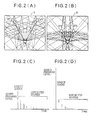
- FIGS. 1(A) to 1(C) are conceptual diagrams illustrating a conventional process for localizing a virtual sound source. Specifically, FIG. 1(A) illustrates arrangement of speakers connected to a sound field control device, FIG. 1(B) illustrates an image of distribution of sound sources of direct and reflected sounds, when sounds to which a sound field effect has been imparted have been reproduced, and FIG. 1(C) is a graph illustrating an echo pattern of a hall (specifically, a graph representing the generation times and levels of direct and reflected sounds).
- volume of sounds reproduced from speakers SP1 to SP5 arranged in a room H as shown in FIG. 1(A) are previously adjusted during setting or the like such that the volumes of the sounds are equal at a sound receiving point (listening position) J.
- the sound field control device When the sound field control device is set so as to impart a sound field effect simulating a sound field of a hall, the sound field control device emits a sound as a direct sound through each speaker after or without performing a specific process on an input signal (i.e., a signal of a sound included in the content) as shown in FIG. 1(B) .
- the sound field control device generates signals of sounds (sound field effect sounds), which simulate a plurality of reflected sounds, from the input signal based on sound field effect information of the hall, and emits the plurality of reflected sounds through the speakers as shown in FIG. 1(B) .
- the generation times and levels of the direct sound and the plurality of reflected sounds (sound field effect sounds) have, for example, a relationship as shown in FIG. 1(C) .
- the sound field effect information is information for reproducing sound field effect sounds.
- the sound field effect information includes impulse response characteristics of a group of reflected sounds generated in an acoustic space such as a concert hall or position information of respective virtual sound sources of the group of reflected sounds.
- each reflected sound in an acoustic space such as a concert hall that the sound field control device generates from an input signal is referred to as a "sound field effect sound" as described above and is distinguished from each reflected sound generated through reflection of the sound from the walls of a listening room.
- the conventional sound field control device has a problem in that an intended sound field effect is not obtained due to a difference in a real reproduction environment such as a difference in the direction or the arrangement of speakers within a room.
- Such a difference in the sound field effect due to a difference in the reproduction environment is caused not only by a difference in the distance between the speakers and the sound receiving point but also by a difference in the size, material (or reflectivity), or the like of the room.
- the sound field effect If the sound field effect is too strong, the sound field effect interferes with listening since the sound field effect sounds harsh. On the other hand, if the sound field effect is too weak, the practical value of the sound field effect function is reduced since it is hard to hear the sound field effect sound.
- EP 1 850 638 A2 discloses a sound field control device capable of adjusting an output balance of the reverberation effect sound and the frequency characteristic of the reverberation effect sound on the basis of the sound circumstances in which a sound system playing the multichannel sound is disposed.
- EP 1 341 399 A2 provides a method and a system for obtaining reproduction sound with realism similar to that of an original sound field regardless of listening positions. A reflected sound pattern added to reproduction sound is calculated so that the reverberation characteristics of the reproduction sound field approximate to the reverberation characteristics of the original sound field.
- the invention includes the following components as the means for solving the above problems.
- the sound field control device of the invention is a device that controls a sound field by imparting a sound field effect to an input audio signal.
- the sound field control device adjusts the volume of each sound field effect sound generated for imparting a sound field effect according to a reproduction environment (i.e., a place where the sound field control device is installed), taking into consideration a reflection state of sound in the reproduction environment.
- the sound field control device stores sound field effect information as information for generating sound field effect sounds corresponding to reflected sounds simulating acoustics of a concert hall or the like.
- the sound field control device generates a plurality of sound field effect sounds based on the sound field effect information, and emits the sound field effect sounds and a direct sound based on the input signal through speakers, thereby generating a sound field desired by a listener around a listening position.
- the sound field effect information stored in the sound field control device is created through simulation or based on acoustic data measured in a real hall or the like.
- the conventional sound field control device may fail to represent a desired sound field effect since the distance between the speakers and the listening position, the acoustics of the room, or the like vary depending on the reproduction environment. Therefore, the sound field control device of the invention comprises an input part through which an audio signal is input; a storage part that stores a first factor obtained by calculating a proportion of energy of direct sound in total energy of sound collected in an adjustment environment within a predetermined time; a sound field generation part that generates a sound field effect sound from the audio signal input through the input part and that outputs the sound field effect sound at a volume corresponding to the first factor; a calculation part that calculates a second factor which represents a ratio of an energy of a direct sound to a total energy of sound which is collected in a reproduction environment and which contains the direct sound; and a correction part that corrects the volume of the sound field effect sound based on a ratio between the first factor and the second factor.
- the sound field control device can correct the volumes of sound field effect sounds (i.e., sounds simulating reflected sounds generated in a music hall or the like), which are generated based on the sound field effect information, based on acoustic states in the reproduction environment, i.e., based on a result of the inspection of states of reflected sounds generated through reflection of the sound from walls in the reproduction environment and then can emit the sound field effect sounds through a plurality of speakers.
- the sound field control device can allow the reproduction environment to approximate an ideal environment, regardless of the reproduction environment, by correcting the volumes of the sound field effect sounds according to the reproduction environment.
- the correction part sets a limit to the ratio between the first factor and the second factor when correcting the volume of the sound field effect sound. Due to this configuration, it is possible to limit the volume of the sound field effect sound within a predetermined range, thereby preventing the occurrence of such a problem.
- a plurality of speakers may be connected to an output part and the first and second factors of the speakers may be different.
- the determination part determines a representative value of the first factors and a representative value of the second factors
- the correction part corrects the volume of the sound field effect sound using the representative values. Accordingly, it is possible to suppress the amount of processing for calculation, thereby reducing calculation load or calculation time.
- first factors A and second factors B may be set respectively for front speakers and rear speakers. Accordingly, in a living room, it is possible to allow the sound field effect to approximate that of an ideal environment even when the listening position is near a rear speaker due to arrangement of a table or a sofa in the living room.
- the sound field control device can allow the reproduction environment to approximate an ideal reproduction environment, regardless of the reproduction environment, by appropriately correcting a difference in the degree of the sound field effect according to the reproduction environment. This allows the listener to enjoy a sense of presence or reality through the sound field effect regardless of the installation place of the sound field control device or speakers.
- FIGS. 2(A) to 2(F) illustrate difference in the sound field effect dependent on nature of the reproduction environments.
- left and right sound sources SP1 and SP2 are installed at symmetrical positions at a distance A from a sound receiving point (listening position) J in a room H and emit sounds toward the sound receiving point J.
- a direct sound reaching directly to the sound receiving point J without reflection with walls is generated, and concurrently a plurality of reflected sounds which are reflected by walls of the room H and which arrive at the sound receiving point J are generated.
- a reproduction space shown in FIG. 2(A) is referred to as a "reproduction environment A".
- left and right sound sources SP1 and SP2 are installed at symmetrical positions at a distance B ( ⁇ A) from a sound receiving point (listening position) J in a room H and emit sounds toward the sound receiving point J.
- ⁇ A distance from a sound receiving point (listening position) J in a room H
- sounds are emitted, a direct sound reaching directly to the sound receiving point J without reflection with walls is generated, and concurrently a plurality of reflected sounds which are reflected by walls of the room H at different positions from those shown in FIG. 2(A) and which arrive at the sound receiving point J are generated.
- a reproduction space shown in FIG. 2(B) is referred to as a "reproduction environment B".
- FIG. 2(C) illustrates a relationship between the levels of a direct sound transmitted to a receiving pint directly with the sound emitted from the right sound source SP2 and reflected sounds which are generated in the room H as the sound is emitted and the times of arrival of the direct and reflected sounds at the sound receiving point J in the reproduction environment A.
- FIG. 2(D) illustrates the same relationship in the reproduction environment B.
- a volume perceived by the listener is the integral of sound pressure (i.e., the sum of energy of direct and reflected sounds) over a certain time. Therefore, in FIGS. 2(C) and 2(D) , sound pressure levels have been scaled such that the total volumes in the reproduction environments A and B are equal.
- both the respective energies of the direct and reflected sounds are proportional to energy of the signal emitted from each sound source
- the energy of the direct sound varies according to the distance between the sound source and the sound receiving point
- the energy of each reflected sound varies according to acoustic characteristics of the reproduction environment.
- the energy of the direct sound greatly changes while the energy of each reflected sound undergoes very little change.
- the ratio of energy between direct and reflected sounds remains the same when the energy of sound emitted from each sound source has been adjusted to equalize volumes at the sound receiving points in the two reproduction environments.
- the volume of each reflected sound from the sound sources SP1 and SP2 located distant from the sound receiving point J is great and the volume of each reflected sound from the sound sources SP1 and SP2 located near the sound receiving point J (i.e., at the small distance B) is small as a result of the adjustment of the energy of sound emitted from each sound source to equalize the total volume at each sound receiving point. That is, the ratio between the levels of direct and reflected sounds in the reproduction environment A is small as shown in FIG. 2(C) and the ratio between the levels of direct and reflected sounds in the reproduction environment B is large as shown in FIG. 2(D) . The listener perceives such different ratios between the levels of direct and reflected sounds as different acoustic atmospheres.
- Results as shown in FIG. 2(E) (in the case of the reproduction environment A) and FIG. 2(F) (in the case of the reproduction environment B) are obtained when an audio content signal has been reproduced by selecting the echo pattern as shown in FIG. 1(C) as a sound field effect in each of the reproduction environments A and B.
- reflected sounds generated through reflection of the sound from walls of the room when the content signal has been reproduced which will hereinafter be referred to as “content signal reflected sounds”
- a sound field effect sound and reflected sounds of the sound field effect sound are shown as solid lines in FIGS.
- the reproduced volume of the content signal which corresponds to the sum of the volumes of the direct and reflected sounds of the content signal, is shown as a dashed line at the left side of the direct sound in each of FIGS. 2(E) and 2(F) such that the reproduced volumes of the content signal are equal in both FIGS. 2(E) and 2(F) .
- the ratio between the energies of direct and reflected sounds of the content signal is small as described above.
- the sound pressure levels of reflected sounds of the content signal generated through reflection in the reproduction environment i.e., in the room
- the sound field effect sounds are rather great compared to the sound field effect sounds as shown in FIG. 2(E) . Therefore, the sound field effect sounds are masked by the reflected sounds of the content signal generated in the room, so that the listener perceives the sound field effect as being weak.
- the ratio between the energies of direct and reflected sounds of the content signal is great as described above.
- the sound pressure levels of reflected sounds of the content signal generated through reflection in the reproduction environment i.e., in the room
- the sound field effect sounds are not masked by the reflected sounds of the content signal generated in the room, so that the listener perceives the sound field effect as being strong.
- Such a difference in the sound field effect due to a difference in the reproduction environment is caused not only by a difference in the distance between the speakers and the sound receiving point but also by a difference in the size, material (or reflectivity), or the like of the room.
- the sound field effect If the sound field effect is too strong, the sound field effect interferes with listening since the sound field effect sound becomes harsh. On the other hand, if the sound field effect is too weak, the practical value of the sound field effect function is reduced since it is hard to hear the sound field effect sound.
- the invention is directed to provide a sound field control device which can appropriately correct a difference in the degree of the sound field effect caused by a difference in the reproduction environments.
- the sound field control device of the invention adjusts the volume of each sound field effect sound generated to impart a sound field effect according to a reproduction environment, taking into consideration a sound reflection condition in the reproduction environment. That is, the sound field control device measures the proportion of a direct sound in a collected sound energy in the reproduction environment. The sound field control device then corrects the proportion of a direct sound in a collected sound energy in an adjustment environment according to the proportion measured in the reproduction environment and imparts a sound field effect having the corrected proportion to an input signal. Accordingly, it is possible to adjust a difference in the degree of the sound field effect due to a difference in the reproduction environment to an appropriate effect level.
- the following are details of the sound field control device of the invention.
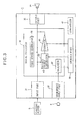
- FIG. 3 is a block diagram illustrating a schematic configuration of a main portion of the sound field control device.
- the sound field control device 1 includes an input part 31, a signal processor 33, an output part 35, a microphone input part 37, a storage part 39, and a controller 41.
- the signal processor 33 includes a test sound generator 51, an effect sound generator 53, a corrector 55, and an analyzer 57.
- a microphone 3 is connected to the microphone input part 37, and an audio content player 5 (for example, a tuner or a DVD player) is connected to the input part 31.
- a speaker 10 is also connected to the output part 35.
- the sound field control device 1 When an audio signal of content output by the content player 5, which will hereinafter be referred to as a "content signal", is input through the input part 31, the sound field control device 1 performs a process such as A/D conversion or decoding on the input signal and outputs the resulting signal to the signal processor 33.
- the signal processor 33 outputs the content signal input through the input part 31 as a sound to the output part 35.
- the signal processor 33 generates sound field effect sounds corresponding to reflected sounds of a hall or the like from the content signal based on sound field effect information read from the storage part 39 and outputs the sound field effect sounds to the output part 35.
- the sound field effect information is information for reproducing sound field effect sounds.
- the sound field effect information includes impulse response characteristics of a group of reflected sounds generated in an acoustic space such as a concert hall and position information of respective virtual sound sources of the group of reflected sounds.
- Each reflected sound in an acoustic space such as a concert hall that the sound field control device generates from the content signal as described above is referred to as a "sound field effect sound" and is distinguished from a reflected sound generated through reflection of the reproduction sound of the content signal from the walls of the room.
- the signal processor 33 corrects the amount of impartment of the sound field effect (i.e., the volume of each sound field effect sound) according to the reproduction environment.
- the output part 35 performs processes such as delaying, D/A conversion, and amplification on the signal of the sound field effect sound and the sound of the content signal input from the signal processor 33 and outputs the resulting signal to the speaker 10.
- the storage part 39 previously stores information of the proportion (which corresponds to a factor A as the first factor) of the direct sound in the reproduced volume (which corresponds to the sum of energy of direct and reflected sounds collected in the previous adjustment environment).
- This factor A is a value that has been previously set based on measurements in a previous adjustment environment (for example, an ideal reproduction environment such as an adjustment room of the manufacturer) when determining the sound field effect information.
- the following method may be used to measure the proportion of the direct sound in the reproduced volume.
- the test sound generator 51 generates an impulse as a test sound signal and the test sound signal is then emitted (output) through the speaker which is a sound source.
- the microphone 3 mounted at a listening position (sound receiving point) 90 collects a direct sound and reflected sounds of the test sound signal, and the analyzer 57 then analyzes the collected sounds.
- the proportion of the direct sound in the reproduced energy can be obtained by calculating, using the measurement results, the ratio (factor A) of energy of the direct sound of the test sound signal to total collected sound energy (volume) within a predetermined time from the output of the test sound signal output. Namely, the first factor is obtained by calculating a proportion of energy of direct sound in total energy of sound collected in an adjustment environment during a predetermined time.
- the test sound generator 51 generates a steady sound such as white noise as a test sound signal and the test sound signal is emitted (output) through the speaker which is a sound source.
- the microphone 3 mounted at a listening position (sound receiving point) 90 collects a direct sound and reflected sounds of the test sound signal and the analyzer 57 then measures energy of the collected sounds.
- a distance between the speaker and the microphone 3 in this state is measured using a well-known method.
- the microphone 3 is mounted at a position slightly deviated from (i.e., near) the listening position 90, and the volume and distance are measured in the same manner.
- the proportion of the direct sound in the reproduced energy can be obtained through measurement and calculation using any of the above two methods.
- the factor A can be obtained using the following equation.
- the factor A obtained in this manner is previously stored in the storage part 39 as described above.
- the storage part 39 also stores a correction factor B (described below) for correcting the volumes of the sound field effect sounds (i.e., sounds simulating reflected sounds (such as reverberation sounds) generated in a hall or the like) output by the analyzer 57.
- the storage part 39 also stores information such as the positional relationship or distance between the sound receiving point (the listening position) and the speaker.
- test sound generator 51 When an environment measurement mode has been set using an operating unit (not shown), the test sound generator 51 generates and outputs a test sound to the output part 35.
- This test sound is a signal emitted through the speaker in order to inspect the acoustics of a place where the speaker 10 is installed (for example, the acoustics of a real reproduction environment such as a living room) .
- the analyzer 57 which corresponds to the calculation part, calculates the proportion of a direct sound of the test sound in the total energy of sounds collected in the reproduction environment based on signals (i.e., collected sound signals) that the microphone 3 generates by receiving the direct sound of the test sound and reflected sounds generated through reflection of the test sound from walls of the installation place and outputs the calculated correction factor B to the storage part 39 to store the correction factor in the storage part 39.
- the calculated proportion corresponds to the correction factor B as the second factor
- the correction factor B is calculated as follows.
- the effect sound generator 53 which corresponds to the sound field generation part, reads sound field effect information representing a sound field effect selected by the listener from the storage part 39 and generates a signal of an effect sound for forming a sound field.
- the effect sound generator 53 may also be configured to generate a preset signal of an effect sound having a volume corresponding to the factor A for each virtual sound source, without reading sound field effect information from the storage part 39.
- both the factor A and the correction factor B represent ratios of energy (volume)
- the square root of A/B is calculated and converted into an amplitude in order to correct the input signal.
- the corrector 55 corrects the signal of the sound field effect sound output by the effect sound generator 53 and outputs the corrected signal to the output part 35.
- FIGS. 4(A) to 4(F) illustrate sound field effects corrected according to a difference in the reproduction environment in the sound field control device of the invention.
- FIG. 2(A) is identical to FIG. 4(A) and FIG. 2(B) is identical to FIG. 4(B).
- FIGS. 4(A), 4(C) , and 4(E) are drawings of the reproduction environment A and FIGS. 4(B), 4(D) , and 4(F) are drawings of the reproduction environment B.
- FIGS. 4(A) is identical to FIG. 4(A) and FIG. 2(B) is identical to FIG. 4(B).
- FIGS. 4(A), 4(C) , and 4(E) are drawings of the reproduction environment A
- FIGS. 4(B), 4(D) , and 4(F) are drawings of the reproduction environment B.
- a direct sound which reached from a speaker to a receiving point directly and reflected sounds generated through reflection of the sound from walls of a room are shown as dotted lines and a sound field effect sound and reflected sounds of the sound field effect sound are shown as solid lines.
- the reproduced volume of an input signal which corresponds to the sum of the energy of the direct and reflected sounds of the content signal, is shown as a dashed line at the left side of the direct sound.
- the reproduced volume of the input signal is scaled such that the reproduced volume of the input signal is shown as being equal in each drawing to equalize the volumes in both the reproduction environments A and B. This is because the volume perceived by the listener is determined based on the integral of sound pressure over a certain time, which corresponds to the sum of energy of direct and reflected sounds.
- the correction factor B 0.3 is obtained in the reproduction environment A shown in FIG. 4(A) , when a test sound (for example, an impulse) is emitted through a sound source SP1 or a sound source SP2 and a direct sound and reflected sounds of a content signal are collected by a microphone 3 mounted at a sound receiving point (listening position) J.
- a test sound for example, an impulse
- the corrector 55 can adjust the reproduced level to a level corresponding to a sound field effect suitable for the reproduction environment A by correcting each sound field effect sound for imparting a sound field effect generated by the effect sound generator 53 using the correction value C (i.e., by calculating the product of the amplitude (sound pressure level) of each virtual sound source of the sound field effect and the correction value C). For example, when the sound field effect shown in FIG. 1(C) has been imparted to the input signal, such volume correction of the sound field effect sound allows the sound pressure levels of the direct sound and the sound field effect sound of the content signal emitted through the sound source SP2 to have those of the sound receiving results shown in FIG. 4(C) .
- the correction factor B 0.68 is obtained in the reproduction environment B shown in FIG. 4(B) , when a test sound (for example, an impulse) is emitted through a sound source SP1 or a sound source SP2 and a direct sound and reflected sounds of a content signal are collected by a microphone 3 mounted at a sound receiving point (listening position) J.
- a test sound for example, an impulse
- the corrector 55 can adjust the reproduced level to a level corresponding to a sound field effect suitable for the reproduction environment B by correcting each sound field effect sound using the correction value C in the same manner as described above. For example, when the sound field effect shown in FIG. 1(C) has been imparted to the input signal, such level correction of the sound field effect sound allows the levels of the direct sound and the sound field effect sound of the content signal emitted through the sound source SP2 to have those of the sound receiving results shown in FIG. 4(D) .
- the amount of impartment of the sound field effect sound is greater than that of the reproduction environment B (i.e., the volume correction value is greater than that of the reproduction environment B) since it is difficult to hear the sound field effect sounds (i.e., the sound field effect sounds are masked) due to the reflected sounds of the content signal that is generated in the reproduction environment A as the direct sound of the content signal is emitted.
- the proportion of the direct sound in the content signal is greater than the proportion of the reflected sounds in the content signal as in the reproduction environment B shown in FIG. 4(B)
- the amount of impartment of the sound field effect sound is smaller than that of the reproduction environment A (i.e., the volume correction value is smaller than that of the reproduction environment A) since the reflected sounds of the content signal generated in the reproduction environment B are smaller than those of the reproduction environment A and thus it is easy to hear the sound field effect sound.
- the corrector 55 can adjust the effect sound level to a level corresponding to the sound field effect suitable for the reproduction environment B by correcting the sound field effect sound generated by the effect sound generator 53 using the correction value C.
- the volumes of the direct sound and the sound field effect sound of the content signal emitted through the sound source SP2 are measured as shown in FIG. 4(E) .
- the levels of the direct sound and the sound field effect sound of the content signal emitted through the sound source SP2 are measured as shown in FIG.
- both the graphs do not exhibit the same characteristics, similar to the graphs of the sound receiving results shown in FIGS. 4(C) and 4(D) , but can be corrected to exhibit closer characteristics than those of FIGS. 4(C) and 4(D) .
- the method of the invention can reduce a sense of discomfort or artificiality, using the amount of change when the sound field effect has been imparted.
- the method of the invention also has an advantage in that costs or processing performance limitations are low, compared to the method in which a measurement environment is recreated, for example, using a process for suppressing reflected sounds in a reproduction environment, since, according to the method of the invention, it is possible to easily implement the means for measuring the respective proportions of the energy of the direct sound and the reflected sounds.
- FIG. 5 illustrates building blocks of the sound field control device and an arrangement of speakers and a microphone.
- a sound field control device 1B shown in FIG. 5 includes a memory 43, an operating unit 45, and a display unit 47 connected to a controller 41 in addition to the components shown in FIG. 3 .
- the memory 43 is a machine readable medium containing program instructions executed by a CPU constituting the controller 41.
- a DVD player 5B is connected as a content player 5 to an input part 31. For example, four speakers 11 to 14 are connected to an output part 35.
- the speakers 11 to 14 are arranged around a listening position 90 to emit sounds toward the listening position 90 which is a sound receiving point. That is, the speaker 11 for a left channel (Lch) and the speaker 12 for a right channel (Rch) are installed at front left and right sides of the listening position 90, respectively.
- the speaker 13 for a left surround channel (SLch) and the speaker 14 for a right surround channel (SRch) are installed at rear left and right sides of the listening position 90, respectively.
- a microphone 3 is installed at the listening position 90.
- PCM signals Digital sound signals of the four channels Lch, Rch, SLch, and SRch are input to an effect sound generator 53 and the effect sound generator 53 generates signals of sound field effect sounds for forming a sound field for virtual sound sources and outputs the generated signals to a corrector 55.
- the corrector 55 corrects the signals of the sound field effect sounds from the effect sound generator 53, and adds and distributes the signals of sound field effect sounds for output through the speakers to generate and output respective signals of sound field effect sounds for the channels Lch, Rch, SLch, and SRch.
- a signal processor 33 includes adders 76 to 79 which add the signals of the sound field effect sounds of the channels output by the corrector 55 to the signals of the channels input from the input part 31.
- the factor A and the correction factor B may be calculated for each speaker in each environment, a plurality of calculated values may be stored. For example, a total of 9 parameters such as factors A1 to A5 and correction factors B1 to B4 are present in the case where five speakers are used when performing adjustment in a previous adjustment environment when determining sound field effect information and four speakers are used as shown in FIG. 5 when performing reproduction through the sound field control device 1.
- a plurality of factors or parameters may be handled using the following several methods.
- a representative value of factors A and a representative value of correction factors B are determined using several methods and the same correction is performed on all speakers. For example, an average or mean value may be employed as the representative value.
- speakers of channels Lch, Cch, and Rch i.e., front speakers
- speakers of channels SLch and SRch i.e., rear speakers
- the listening position is often set near rear speakers due to constrains of arrangement of a table or a sofa in the living room.
- the factors A and the correction factors B may be changed respectively for the front speakers and the rear speakers. For example, in this case, if representative values of the factors A and the correction factors B are set for the three front speakers and representative values of the factors A and the correction factors B are set for the two rear speakers, it is possible to perform adjustment according to the listening position using a small number of adjustment parameters.
- the controller 41 which corresponds to the determination part, calculates a representative value of factors A or a representative value of correction factors B from the factors A or the correction factors B and stores the representative values in the storage part 39. Then, the corrector 55 may be constructed to read the representative value of the factors A, the representative value of the correction factors B, or the individual values these values from the storage part 39 and to calculate the correction value C of the sound field effect using the read values.
- measurement of the respective proportions of the direct sound and the reflected sounds in the reproduction environment may be performed once when the environment is established.
- the measurement results may be stored in a nonvolatile memory (i.e., the storage part 39) included in the sound field control device 1.
- the corrector 55 may be installed at the input side or the output side of the effect sound generator 53 in the case where only one representative value is set for each of the factors A and the correction factors B.
- the sound field control device may be constructed such that correction is performed for each individual virtual sound source before signal summation is performed for each speaker, which is an output location, at the effect sound generator 53 or the output part 35.
- the sound field control device may be constructed such that level correction is performed for each speaker, which is an output location, at the output side of the sound field effect processing block (i.e., the effect sound generator 53).
- the correction factor A / B is significantly or even excessively great or small, it is possible to perform a process for limiting the correction factor A / B within a predetermined range, for example, to limit the range of values for correction factor using limit values or to introduce a function as a scale factor of the correction. That is, the sound field may be changed to one different from the assumed sound field since the "volumes" of the sound field effect sounds are corrected. This change may be limited within a predetermined range using a method of limiting the range of the correction factors or scaling the correction factors (for example, using a method of suppressing the increase of the correction factor as the correction factor increases). Accordingly, it is possible to prevent the occurrence of the processing problem that the sound field effect sound becomes greater than the direct sound.
- the inventive sound field control device allows the actual reproduction environment to approximate the ideal reproduction environment, regardless of the nature of the actual reproduction environment, by correcting the volumes of the sound field effect sounds according to the nature of the reproduction environment.
Landscapes
- Engineering & Computer Science (AREA)
- Multimedia (AREA)
- Physics & Mathematics (AREA)
- Acoustics & Sound (AREA)
- Signal Processing (AREA)
- Stereophonic System (AREA)
- Circuit For Audible Band Transducer (AREA)
Claims (4)
- Eine Schallfeld-Steuervorrichtung umfassend:ein Eingabeelement, über welches ein Audiosignal eingegeben ist;ein Speicherelement, welches einen ersten Faktor speichert, welcher durch Berechnen eines Energieverhältnisses eines Direktschalls in einer in einer Einstellungsumgebung innerhalb einer vorbestimmten Zeit gesammelten Gesamtschallenergie erhalten wird;ein Schallfeld-Erzeugungselement, welches einen Schallfeldeffektschall aus dem durch das Eingabeelement eingegebenen Audiosignal erzeugt und welches den Schallfeldeffektschall bei einer Lautstärke entsprechend dem ersten Faktor ausgibt;ein Berechnungselement, welches einen zweiten Faktor berechnet, welcher ein Verhältnis einer Energie eines Direktschalls zu einer Schallenergie, welche in einer Wiedergabeumgebung gesammelt ist und welche den Direktschall enthält, darstellt; undein Korrekturelement, welches die Lautstärke des Schallfeldeffektschalls basierend auf einem Verhältnis zwischen dem ersten Faktor und dem zweiten Faktor korrigiert.
- Die Schallfeld-Steuervorrichtung gemäß Anspruch 1, wobei das Korrekturelement eine Grenze zu dem Verhältnis zwischen dem ersten Faktor und dem zweiten Faktor einstellt, wenn die Lautstärke des Schallfeldeffektschalls korrigiert wird.
- Die Schallfeld-Steuervorrichtung gemäß Anspruch 1 oder 2,
wobei das Speicherelement eine Vielzahl von ersten Faktoren in Korrespondenz zu einer Vielzahl von Lautsprechern speichert, falls die Vielzahl der Lautsprecher zum Wiedergeben von Schall verwendet wird,
wobei die Berechnungseinheit eine Vielzahl von zweiten Faktoren in Korrespondenz zu einer Vielzahl von Lautsprechern berechnet, falls die Vielzahl der Lautsprecher zum Wiedergeben von Schall verwendet wird,
wobei die Schallfeld-Steuervorrichtung weiter ein Bestimmungselement umfasst, welches einen repräsentativen Wert der ersten Faktoren bestimmt, falls die ersten Faktoren der entsprechenden Lautsprecher unterschiedlich sind, und welches einen repräsentativen Wert der zweiten Faktoren bestimmt, falls die zweiten Faktoren der entsprechenden Lautsprecher unterschiedlich sind, und
wobei, wenn das Bestimmungselement den repräsentativen Wert bestimmt hat, das Korrekturelement die Lautstärke des durch das Schallfeld-Erzeugungselement erzeugten Schallfeldeffektschalls mittels des durch das Bestimmungselement bestimmten repräsentativen Werts korrigiert. - Die Schallfeld-Steuervorrichtung gemäß Anspruch 1, wobei das Korrekturelement die Lautstärke des Schallfeldeffektschalls basierend auf dem Verhältnis zwischen dem ersten Faktor und dem zweiten Faktor korrigiert, sodass die Lautstärke des Schallfeldeffektschalls sich verringert, wenn sich die Lautstärke des Direktschalls in der Wiedergabeumgebung erhöht.
Applications Claiming Priority (1)
| Application Number | Priority Date | Filing Date | Title |
|---|---|---|---|
| JP2009120792 | 2009-05-19 |
Publications (3)
| Publication Number | Publication Date |
|---|---|
| EP2254355A2 EP2254355A2 (de) | 2010-11-24 |
| EP2254355A3 EP2254355A3 (de) | 2013-06-26 |
| EP2254355B1 true EP2254355B1 (de) | 2015-07-01 |
Family
ID=42575799
Family Applications (1)
| Application Number | Title | Priority Date | Filing Date |
|---|---|---|---|
| EP10163247.9A Active EP2254355B1 (de) | 2009-05-19 | 2010-05-19 | Schallfeldsteuerungsvorrichtung |
Country Status (3)
| Country | Link |
|---|---|
| US (1) | US8488802B2 (de) |
| EP (1) | EP2254355B1 (de) |
| JP (2) | JP5516060B2 (de) |
Families Citing this family (10)
| Publication number | Priority date | Publication date | Assignee | Title |
|---|---|---|---|---|
| GB0303812D0 (en) | 2003-02-19 | 2003-03-26 | British Telecomm | Tracking audience size |
| CN104081334B (zh) * | 2011-11-30 | 2018-10-26 | 诺基亚技术有限公司 | 用于音频反应ui信息的装置和方法以及显示器 |
| EP3483874B1 (de) * | 2013-03-05 | 2021-04-28 | Apple Inc. | Regelung der strahlverteilung einer lautsprecheranordnung auf basis des standortes eines oder mehrerer zuhörer |
| CN103702259B (zh) | 2013-12-31 | 2017-12-12 | 北京智谷睿拓技术服务有限公司 | 交互装置及交互方法 |
| CN103747409B (zh) * | 2013-12-31 | 2017-02-08 | 北京智谷睿拓技术服务有限公司 | 扬声装置、扬声方法及交互设备 |
| US9820047B2 (en) * | 2015-09-01 | 2017-11-14 | Panasonic Intellectual Property Management Co., Ltd. | Signal processing method and speaker system |
| JP6540600B2 (ja) * | 2016-05-25 | 2019-07-10 | ヤマハ株式会社 | 効果音生成装置、効果音生成方法およびプログラム |
| KR102334070B1 (ko) * | 2018-01-18 | 2021-12-03 | 삼성전자주식회사 | 전자 장치 및 그 제어 방법 |
| CN110364161A (zh) * | 2019-08-22 | 2019-10-22 | 北京小米智能科技有限公司 | 响应语音信号的方法、电子设备、介质及系统 |
| JP7532793B2 (ja) * | 2020-02-10 | 2024-08-14 | ヤマハ株式会社 | 音量調整装置および音量調整方法 |
Family Cites Families (14)
| Publication number | Priority date | Publication date | Assignee | Title |
|---|---|---|---|---|
| JPH02309800A (ja) * | 1989-05-24 | 1990-12-25 | Matsushita Electric Ind Co Ltd | 音場制御装置 |
| JPH03194599A (ja) * | 1989-12-25 | 1991-08-26 | Fujita Corp | 室内音響シミユレーションシステム |
| JP3107599B2 (ja) * | 1991-08-14 | 2000-11-13 | 富士通テン株式会社 | 音場制御装置 |
| JP3366367B2 (ja) * | 1993-03-16 | 2003-01-14 | 松下電器産業株式会社 | 音場補正装置 |
| JP3191512B2 (ja) * | 1993-07-22 | 2001-07-23 | ヤマハ株式会社 | 音響特性補正装置 |
| JP2755208B2 (ja) | 1995-03-30 | 1998-05-20 | ヤマハ株式会社 | 音場制御装置 |
| JPH09130887A (ja) * | 1995-10-27 | 1997-05-16 | Olympus Optical Co Ltd | 音響信号呈示装置 |
| JP4059478B2 (ja) * | 2002-02-28 | 2008-03-12 | パイオニア株式会社 | 音場制御方法及び音場制御システム |
| JP4062959B2 (ja) * | 2002-04-26 | 2008-03-19 | ヤマハ株式会社 | 残響付与装置、残響付与方法、インパルス応答生成装置、インパルス応答生成方法、残響付与プログラム、インパルス応答生成プログラムおよび記録媒体 |
| WO2006009028A1 (ja) * | 2004-07-20 | 2006-01-26 | Pioneer Corporation | 音響再生装置および音響再生システム |
| JP4222276B2 (ja) * | 2004-08-27 | 2009-02-12 | ソニー株式会社 | 再生システム |
| US8094826B2 (en) * | 2006-01-03 | 2012-01-10 | Sl Audio A/S | Method and system for equalizing a loudspeaker in a room |
| JP4668118B2 (ja) * | 2006-04-28 | 2011-04-13 | ヤマハ株式会社 | 音場制御装置 |
| US8670570B2 (en) * | 2006-11-07 | 2014-03-11 | Stmicroelectronics Asia Pacific Pte., Ltd. | Environmental effects generator for digital audio signals |
-
2010
- 2010-05-18 US US12/782,607 patent/US8488802B2/en active Active
- 2010-05-18 JP JP2010114675A patent/JP5516060B2/ja active Active
- 2010-05-19 EP EP10163247.9A patent/EP2254355B1/de active Active
-
2014
- 2014-04-03 JP JP2014076585A patent/JP5725228B2/ja not_active Expired - Fee Related
Also Published As
| Publication number | Publication date |
|---|---|
| EP2254355A2 (de) | 2010-11-24 |
| US8488802B2 (en) | 2013-07-16 |
| JP5725228B2 (ja) | 2015-05-27 |
| JP2014143740A (ja) | 2014-08-07 |
| EP2254355A3 (de) | 2013-06-26 |
| US20100296658A1 (en) | 2010-11-25 |
| JP5516060B2 (ja) | 2014-06-11 |
| JP2011004394A (ja) | 2011-01-06 |
Similar Documents
| Publication | Publication Date | Title |
|---|---|---|
| EP2254355B1 (de) | Schallfeldsteuerungsvorrichtung | |
| US10812925B2 (en) | Audio processing device and method therefor | |
| JP6818841B2 (ja) | 少なくとも一つのフィードバック遅延ネットワークを使ったマルチチャネル・オーディオに応答したバイノーラル・オーディオの生成 | |
| US8199921B2 (en) | Sound field controlling device | |
| US20080260170A1 (en) | Signal processing apparatus, signal processing method, and recording medium having program recorded thereon | |
| US11917393B2 (en) | Sound field support method, sound field support apparatus and a non-transitory computer-readable storage medium storing a program | |
| JP2017507525A (ja) | 少なくとも一つのフィードバック遅延ネットワークを使ったマルチチャネル・オーディオに応答したバイノーラル・オーディオの生成 | |
| CN117835140B (zh) | 一种用于家庭影院系统的声音优化方法 | |
| US20160212563A1 (en) | Audio Signal Processing Apparatus | |
| US20250193633A1 (en) | Audio signal processing method and audio signal processing apparatus | |
| US7572970B2 (en) | Digital piano apparatus, method for synthesis of sound fields for digital piano, and computer-readable storage medium | |
| EP4060656A1 (de) | Audiosignalverarbeitungsverfahren, audiosignalverarbeitungsvorrichtung und audiosignalverarbeitungsprogramm | |
| US11805385B2 (en) | Audio signal processing method, audio signal processing apparatus and a non-transitory computer-readable storage medium storing a program | |
| JP4894422B2 (ja) | 音響発生装置 | |
| EP4060655B1 (de) | Audiosignalverarbeitungsverfahren, audiosignalverarbeitungsgerät und audiosignalverarbeitungsprogramm |
Legal Events
| Date | Code | Title | Description |
|---|---|---|---|
| PUAI | Public reference made under article 153(3) epc to a published international application that has entered the european phase |
Free format text: ORIGINAL CODE: 0009012 |
|
| AK | Designated contracting states |
Kind code of ref document: A2 Designated state(s): AL AT BE BG CH CY CZ DE DK EE ES FI FR GB GR HR HU IE IS IT LI LT LU LV MC MK MT NL NO PL PT RO SE SI SK SM TR |
|
| AX | Request for extension of the european patent |
Extension state: BA ME RS |
|
| PUAL | Search report despatched |
Free format text: ORIGINAL CODE: 0009013 |
|
| AK | Designated contracting states |
Kind code of ref document: A3 Designated state(s): AL AT BE BG CH CY CZ DE DK EE ES FI FR GB GR HR HU IE IS IT LI LT LU LV MC MK MT NL NO PL PT RO SE SI SK SM TR |
|
| AX | Request for extension of the european patent |
Extension state: BA ME RS |
|
| RIC1 | Information provided on ipc code assigned before grant |
Ipc: H04S 7/00 20060101AFI20130522BHEP |
|
| 17P | Request for examination filed |
Effective date: 20131217 |
|
| RBV | Designated contracting states (corrected) |
Designated state(s): AL AT BE BG CH CY CZ DE DK EE ES FI FR GB GR HR HU IE IS IT LI LT LU LV MC MK MT NL NO PL PT RO SE SI SK SM TR |
|
| 17Q | First examination report despatched |
Effective date: 20140624 |
|
| GRAP | Despatch of communication of intention to grant a patent |
Free format text: ORIGINAL CODE: EPIDOSNIGR1 |
|
| INTG | Intention to grant announced |
Effective date: 20150122 |
|
| GRAS | Grant fee paid |
Free format text: ORIGINAL CODE: EPIDOSNIGR3 |
|
| GRAA | (expected) grant |
Free format text: ORIGINAL CODE: 0009210 |
|
| AK | Designated contracting states |
Kind code of ref document: B1 Designated state(s): AL AT BE BG CH CY CZ DE DK EE ES FI FR GB GR HR HU IE IS IT LI LT LU LV MC MK MT NL NO PL PT RO SE SI SK SM TR |
|
| REG | Reference to a national code |
Ref country code: GB Ref legal event code: FG4D |
|
| REG | Reference to a national code |
Ref country code: AT Ref legal event code: REF Ref document number: 734569 Country of ref document: AT Kind code of ref document: T Effective date: 20150715 Ref country code: CH Ref legal event code: EP |
|
| REG | Reference to a national code |
Ref country code: IE Ref legal event code: FG4D |
|
| REG | Reference to a national code |
Ref country code: DE Ref legal event code: R096 Ref document number: 602010025508 Country of ref document: DE |
|
| REG | Reference to a national code |
Ref country code: AT Ref legal event code: MK05 Ref document number: 734569 Country of ref document: AT Kind code of ref document: T Effective date: 20150701 |
|
| REG | Reference to a national code |
Ref country code: NL Ref legal event code: MP Effective date: 20150701 |
|
| REG | Reference to a national code |
Ref country code: LT Ref legal event code: MG4D |
|
| PG25 | Lapsed in a contracting state [announced via postgrant information from national office to epo] |
Ref country code: GR Free format text: LAPSE BECAUSE OF FAILURE TO SUBMIT A TRANSLATION OF THE DESCRIPTION OR TO PAY THE FEE WITHIN THE PRESCRIBED TIME-LIMIT Effective date: 20151002 Ref country code: LV Free format text: LAPSE BECAUSE OF FAILURE TO SUBMIT A TRANSLATION OF THE DESCRIPTION OR TO PAY THE FEE WITHIN THE PRESCRIBED TIME-LIMIT Effective date: 20150701 Ref country code: LT Free format text: LAPSE BECAUSE OF FAILURE TO SUBMIT A TRANSLATION OF THE DESCRIPTION OR TO PAY THE FEE WITHIN THE PRESCRIBED TIME-LIMIT Effective date: 20150701 Ref country code: NO Free format text: LAPSE BECAUSE OF FAILURE TO SUBMIT A TRANSLATION OF THE DESCRIPTION OR TO PAY THE FEE WITHIN THE PRESCRIBED TIME-LIMIT Effective date: 20151001 Ref country code: FI Free format text: LAPSE BECAUSE OF FAILURE TO SUBMIT A TRANSLATION OF THE DESCRIPTION OR TO PAY THE FEE WITHIN THE PRESCRIBED TIME-LIMIT Effective date: 20150701 |
|
| PG25 | Lapsed in a contracting state [announced via postgrant information from national office to epo] |
Ref country code: AT Free format text: LAPSE BECAUSE OF FAILURE TO SUBMIT A TRANSLATION OF THE DESCRIPTION OR TO PAY THE FEE WITHIN THE PRESCRIBED TIME-LIMIT Effective date: 20150701 Ref country code: PL Free format text: LAPSE BECAUSE OF FAILURE TO SUBMIT A TRANSLATION OF THE DESCRIPTION OR TO PAY THE FEE WITHIN THE PRESCRIBED TIME-LIMIT Effective date: 20150701 Ref country code: HR Free format text: LAPSE BECAUSE OF FAILURE TO SUBMIT A TRANSLATION OF THE DESCRIPTION OR TO PAY THE FEE WITHIN THE PRESCRIBED TIME-LIMIT Effective date: 20150701 Ref country code: IS Free format text: LAPSE BECAUSE OF FAILURE TO SUBMIT A TRANSLATION OF THE DESCRIPTION OR TO PAY THE FEE WITHIN THE PRESCRIBED TIME-LIMIT Effective date: 20151101 Ref country code: ES Free format text: LAPSE BECAUSE OF FAILURE TO SUBMIT A TRANSLATION OF THE DESCRIPTION OR TO PAY THE FEE WITHIN THE PRESCRIBED TIME-LIMIT Effective date: 20150701 Ref country code: SE Free format text: LAPSE BECAUSE OF FAILURE TO SUBMIT A TRANSLATION OF THE DESCRIPTION OR TO PAY THE FEE WITHIN THE PRESCRIBED TIME-LIMIT Effective date: 20150701 Ref country code: PT Free format text: LAPSE BECAUSE OF FAILURE TO SUBMIT A TRANSLATION OF THE DESCRIPTION OR TO PAY THE FEE WITHIN THE PRESCRIBED TIME-LIMIT Effective date: 20151102 |
|
| REG | Reference to a national code |
Ref country code: DE Ref legal event code: R097 Ref document number: 602010025508 Country of ref document: DE |
|
| REG | Reference to a national code |
Ref country code: FR Ref legal event code: PLFP Year of fee payment: 7 |
|
| PG25 | Lapsed in a contracting state [announced via postgrant information from national office to epo] |
Ref country code: EE Free format text: LAPSE BECAUSE OF FAILURE TO SUBMIT A TRANSLATION OF THE DESCRIPTION OR TO PAY THE FEE WITHIN THE PRESCRIBED TIME-LIMIT Effective date: 20150701 Ref country code: IT Free format text: LAPSE BECAUSE OF FAILURE TO SUBMIT A TRANSLATION OF THE DESCRIPTION OR TO PAY THE FEE WITHIN THE PRESCRIBED TIME-LIMIT Effective date: 20150701 Ref country code: DK Free format text: LAPSE BECAUSE OF FAILURE TO SUBMIT A TRANSLATION OF THE DESCRIPTION OR TO PAY THE FEE WITHIN THE PRESCRIBED TIME-LIMIT Effective date: 20150701 Ref country code: CZ Free format text: LAPSE BECAUSE OF FAILURE TO SUBMIT A TRANSLATION OF THE DESCRIPTION OR TO PAY THE FEE WITHIN THE PRESCRIBED TIME-LIMIT Effective date: 20150701 Ref country code: SK Free format text: LAPSE BECAUSE OF FAILURE TO SUBMIT A TRANSLATION OF THE DESCRIPTION OR TO PAY THE FEE WITHIN THE PRESCRIBED TIME-LIMIT Effective date: 20150701 |
|
| PLBE | No opposition filed within time limit |
Free format text: ORIGINAL CODE: 0009261 |
|
| STAA | Information on the status of an ep patent application or granted ep patent |
Free format text: STATUS: NO OPPOSITION FILED WITHIN TIME LIMIT |
|
| PG25 | Lapsed in a contracting state [announced via postgrant information from national office to epo] |
Ref country code: RO Free format text: LAPSE BECAUSE OF FAILURE TO SUBMIT A TRANSLATION OF THE DESCRIPTION OR TO PAY THE FEE WITHIN THE PRESCRIBED TIME-LIMIT Effective date: 20150701 |
|
| 26N | No opposition filed |
Effective date: 20160404 |
|
| PG25 | Lapsed in a contracting state [announced via postgrant information from national office to epo] |
Ref country code: BE Free format text: LAPSE BECAUSE OF NON-PAYMENT OF DUE FEES Effective date: 20160531 Ref country code: SI Free format text: LAPSE BECAUSE OF FAILURE TO SUBMIT A TRANSLATION OF THE DESCRIPTION OR TO PAY THE FEE WITHIN THE PRESCRIBED TIME-LIMIT Effective date: 20150701 |
|
| PG25 | Lapsed in a contracting state [announced via postgrant information from national office to epo] |
Ref country code: LU Free format text: LAPSE BECAUSE OF FAILURE TO SUBMIT A TRANSLATION OF THE DESCRIPTION OR TO PAY THE FEE WITHIN THE PRESCRIBED TIME-LIMIT Effective date: 20160519 Ref country code: BE Free format text: LAPSE BECAUSE OF FAILURE TO SUBMIT A TRANSLATION OF THE DESCRIPTION OR TO PAY THE FEE WITHIN THE PRESCRIBED TIME-LIMIT Effective date: 20150701 |
|
| REG | Reference to a national code |
Ref country code: CH Ref legal event code: PL |
|
| PG25 | Lapsed in a contracting state [announced via postgrant information from national office to epo] |
Ref country code: LI Free format text: LAPSE BECAUSE OF NON-PAYMENT OF DUE FEES Effective date: 20160531 Ref country code: CH Free format text: LAPSE BECAUSE OF NON-PAYMENT OF DUE FEES Effective date: 20160531 |
|
| REG | Reference to a national code |
Ref country code: IE Ref legal event code: MM4A |
|
| REG | Reference to a national code |
Ref country code: FR Ref legal event code: PLFP Year of fee payment: 8 |
|
| PG25 | Lapsed in a contracting state [announced via postgrant information from national office to epo] |
Ref country code: IE Free format text: LAPSE BECAUSE OF NON-PAYMENT OF DUE FEES Effective date: 20160519 |
|
| PG25 | Lapsed in a contracting state [announced via postgrant information from national office to epo] |
Ref country code: NL Free format text: LAPSE BECAUSE OF FAILURE TO SUBMIT A TRANSLATION OF THE DESCRIPTION OR TO PAY THE FEE WITHIN THE PRESCRIBED TIME-LIMIT Effective date: 20150701 |
|
| PGFP | Annual fee paid to national office [announced via postgrant information from national office to epo] |
Ref country code: GB Payment date: 20170517 Year of fee payment: 8 Ref country code: FR Payment date: 20170413 Year of fee payment: 8 |
|
| PG25 | Lapsed in a contracting state [announced via postgrant information from national office to epo] |
Ref country code: HU Free format text: LAPSE BECAUSE OF FAILURE TO SUBMIT A TRANSLATION OF THE DESCRIPTION OR TO PAY THE FEE WITHIN THE PRESCRIBED TIME-LIMIT; INVALID AB INITIO Effective date: 20100519 Ref country code: CY Free format text: LAPSE BECAUSE OF FAILURE TO SUBMIT A TRANSLATION OF THE DESCRIPTION OR TO PAY THE FEE WITHIN THE PRESCRIBED TIME-LIMIT Effective date: 20150701 Ref country code: SM Free format text: LAPSE BECAUSE OF FAILURE TO SUBMIT A TRANSLATION OF THE DESCRIPTION OR TO PAY THE FEE WITHIN THE PRESCRIBED TIME-LIMIT Effective date: 20150701 |
|
| PG25 | Lapsed in a contracting state [announced via postgrant information from national office to epo] |
Ref country code: MK Free format text: LAPSE BECAUSE OF FAILURE TO SUBMIT A TRANSLATION OF THE DESCRIPTION OR TO PAY THE FEE WITHIN THE PRESCRIBED TIME-LIMIT Effective date: 20150701 Ref country code: TR Free format text: LAPSE BECAUSE OF FAILURE TO SUBMIT A TRANSLATION OF THE DESCRIPTION OR TO PAY THE FEE WITHIN THE PRESCRIBED TIME-LIMIT Effective date: 20150701 Ref country code: MT Free format text: LAPSE BECAUSE OF NON-PAYMENT OF DUE FEES Effective date: 20160531 Ref country code: MC Free format text: LAPSE BECAUSE OF FAILURE TO SUBMIT A TRANSLATION OF THE DESCRIPTION OR TO PAY THE FEE WITHIN THE PRESCRIBED TIME-LIMIT Effective date: 20150701 |
|
| PG25 | Lapsed in a contracting state [announced via postgrant information from national office to epo] |
Ref country code: BG Free format text: LAPSE BECAUSE OF FAILURE TO SUBMIT A TRANSLATION OF THE DESCRIPTION OR TO PAY THE FEE WITHIN THE PRESCRIBED TIME-LIMIT Effective date: 20150701 |
|
| PG25 | Lapsed in a contracting state [announced via postgrant information from national office to epo] |
Ref country code: AL Free format text: LAPSE BECAUSE OF FAILURE TO SUBMIT A TRANSLATION OF THE DESCRIPTION OR TO PAY THE FEE WITHIN THE PRESCRIBED TIME-LIMIT Effective date: 20150701 |
|
| GBPC | Gb: european patent ceased through non-payment of renewal fee |
Effective date: 20180519 |
|
| PG25 | Lapsed in a contracting state [announced via postgrant information from national office to epo] |
Ref country code: FR Free format text: LAPSE BECAUSE OF NON-PAYMENT OF DUE FEES Effective date: 20180531 Ref country code: GB Free format text: LAPSE BECAUSE OF NON-PAYMENT OF DUE FEES Effective date: 20180519 |
|
| PGFP | Annual fee paid to national office [announced via postgrant information from national office to epo] |
Ref country code: DE Payment date: 20250521 Year of fee payment: 16 |