EP2254100A2 - Drahtloser Detektor mit einem Prozessor - Google Patents
Drahtloser Detektor mit einem Prozessor Download PDFInfo
- Publication number
- EP2254100A2 EP2254100A2 EP10174554A EP10174554A EP2254100A2 EP 2254100 A2 EP2254100 A2 EP 2254100A2 EP 10174554 A EP10174554 A EP 10174554A EP 10174554 A EP10174554 A EP 10174554A EP 2254100 A2 EP2254100 A2 EP 2254100A2
- Authority
- EP
- European Patent Office
- Prior art keywords
- sensor
- detector
- sensors
- during
- intervals
- Prior art date
- Legal status (The legal status is an assumption and is not a legal conclusion. Google has not performed a legal analysis and makes no representation as to the accuracy of the status listed.)
- Withdrawn
Links
Images


Classifications
-
- G—PHYSICS
- G08—SIGNALLING
- G08B—SIGNALLING SYSTEMS, e.g. PERSONAL CALLING SYSTEMS; ORDER TELEGRAPHS; ALARM SYSTEMS
- G08B29/00—Checking or monitoring of signalling or alarm systems; Prevention or correction of operating errors, e.g. preventing unauthorised operation
- G08B29/18—Prevention or correction of operating errors
- G08B29/181—Prevention or correction of operating errors due to failing power supply
-
- G—PHYSICS
- G08—SIGNALLING
- G08B—SIGNALLING SYSTEMS, e.g. PERSONAL CALLING SYSTEMS; ORDER TELEGRAPHS; ALARM SYSTEMS
- G08B25/00—Alarm systems in which the location of the alarm condition is signalled to a central station, e.g. fire or police telegraphic systems
- G08B25/01—Alarm systems in which the location of the alarm condition is signalled to a central station, e.g. fire or police telegraphic systems characterised by the transmission medium
- G08B25/10—Alarm systems in which the location of the alarm condition is signalled to a central station, e.g. fire or police telegraphic systems characterised by the transmission medium using wireless transmission systems
Definitions
- the invention pertains to wireless detectors usable in alarm systems. More particularly, the invention pertains to such detectors which incorporate single die, multi-function, programmed processors configured for energy efficient battery powered operation.
- Wireless ambient condition detectors are known. Such detectors, most conveniently, have been battery powered so that they may easily be mounted in a variety of locations without any need for power or communications cables. Known wireless detectors, while effective, have used energy at a rate which did not provide as long a battery life as desirable.
- Known detectors have used separate integrated circuits to interface with different types of sensors such as smoke sensors and heat sensors. Signal processing has in turn required other circuits.
- ASIC application specific integrated circuits
- Known detectors have used a different ASIC for communications and low battery detection. Since the ASPIC coupled to the respective smoke sensor and the communications ASIC operate autonomously, they create irregular and unpredictable current draw profiles. In known detectors, this irregular and unpredictable current draw profile impedes accurate battery voltage measurements. As a result of these unpredictable current draws, low battery trouble, voltage thresholds have had to be set higher than desirable. This also contributes to shorter battery life.
- sensitivity compensation to take into account dust and aging of a sensing chamber, has in some known systems been carried out at a system control panel. Smaller, less expensive control panels may not have the processing capability to implement this function.
- One known type of detector based compensation provides a maximum incremental change which can take place in the detector during each compensation cycle. While this process does provide compensation over a period of time, the greater the extent of the required compensation, the longer is the time interval that is required to achieve a desired sensitivity.
- heat sensors can be susceptible to nuisance conditions such as electrical noise from static electricity, power surges, radio-frequency interference, as well as thermal noise both from turning the sensor on and off as well as thermal variations from the ambient environment. It has been known to use reference heat sensors to compensate for temperature changes. Such reference heat sensors not only add additional cost to the respective detector but are limited in the thermal noise which can be rejected.
- a wireless detector incorporates a single chip, or die, integrated control element.
- the element includes an integrally formed processor, read-write, reprogrammable read only memory or one time programmable read only memory. Different memory types can be formed on the same die.
- the same chip can include programmable timers, and I/O ports for both analog and digital inputs or outputs.
- the detector includes a photoelectric smoke sensor and at least one heat sensor.
- Executable instructions implement a common sensing cycle for both types of sensors.
- Two heat sensors can be incorporated into a disclosed embodiment.
- a battery used to power the detector provides an output voltage in a predetermined monitorable range which will support successful operation.
- a voltage multiplier circuit coupled to the battery, provides a higher voltage to drive an audible output device in accordance with processor supplied modulation.
- the detector conserves energy, and extends battery life, by performing sensor sampling and signal processing functions for that sample interval during a single active interval. Then, the circuitry enters a low power, inactive state until the next activate interrupt arrives.
- a disclosed embodiment combines different types of sensors, some of which have longer stabilization intervals then others. Different types of sensors can be activated simultaneously. Those with relatively short stabilization intervals can be sampled and the respective signal, or signals, processed, at least in part, during longer stabilization and processing intervals for other types of sensors. This overlap contributes to minimal over-all energy usage during each active interval.
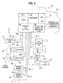
- Fig. 1 illustrates a monitoring system 10 in accordance with the present invention.
- the system 10 incorporates a system control element 12 which could incorporate one or more programmed processors and pre-stored executable instructions. It will be understood that the exact details of the control element 12 are not a limitation of the present invention.
- the control element 12 is coupled to a wireless antenna 12a wherein the system 10 has been implemented using RF-type wireless transmissions.
- Other forms of wireless transmission come within the spirit and scope of the present invention.
- the members of a plurality of electrical units 16 are wirelessly coupled to control element 12.
- the members of the plurality 16i could be implemented as battery powered units having one or more ambient condition sensors for purposes of monitoring a region.
- the sensors could be responsive to smoke, gas, position, flow, intrusion, movement or the like all without limitation of present invention.
- the electrical units 16 via respective antennas, such as antenna 16i-1 communicate status information and information pertaining to the condition being monitored to the control element 12.
- Various levels of processing of the signals from the respective sensor or sensors at the unit 16i can be carried out locally and the results thereof transmitted via antennae 16i-1 and 12a to control element 12.
- system 10 can incorporate one or more wired communication links, representatively illustrated as link 18, coupled to control element 12.
- Members of a plurality of electrical units 20 can be coupled to link 18 for communication with control element 12.
- the members of the plurality 20 could incorporate detectors of ambient conditions as well as output or control devices all without limitation of the present invention.
- Fig. 2 illustrates more details of a representative member 16i of the plurality 16.
- the electrical unit 16i is carried in a housing 16i-2.
- the housing 16i-2 can be mounted to a selected surface.
- the unit 16i includes a single die, programmed, control element 30.
- the element 30 includes a processor 30a, read/write memory 30b, and non-volatile memory 30c.
- the read/write memory 30b can be implemented using a variety of random access or quasi random access technologies as would be understood by those of skill in the art within the spirit and scope of the present invention.
- the non-volatile memory 30c can be implemented with a variety of non-volatile technologies including OPT, flash memory, EEPROM or PROM storage circuitry or combinations thereof. It will be understood that executable instructions and calibration parameters can be stored in one or more types of non-volatile memory all on the same die. By use of EEPROM or other types of reprogrammable storage, parameters and/or executable instructions can be up-dated wirelessly from time to time as a result of commands and files received from the control element 12. In addition, when the unit 16i is being manufactured, executable instructions can be written therein, executed and/or modified without having to be delayed by expensive revisions to mask sets.
- the control element 30 includes, integrated on the same die, interrupt and I/O ports 30d. Circuitry 30a, 30b, 30c and 30d are all interconnected on the single die resulting in a single chip element which also promotes manufacturability.
- the unit 16i also includes a wireless interface 34 coupled to the I/O ports 30d and antenna 16i-1.
- a wireless interface 34 coupled to the I/O ports 30d and antenna 16i-1.
- a variety of wireless interfaces can be used in the unit 16i without departing from the spirit and scope of the present invention so long as the interfaces enable the respective units, such as the unit 16i to communicate with the control element 12 wirelessly.
- communication will be bidirectional although unidirectional communication from the respective electrical units 16 comes within the spirit and scope of the present invention.
- the illustrated electrical unit 16i also includes a smoke chamber 36a.
- Chamber 36a is configured to permit an inflow and outflow of smoke carrying ambient atmosphere in the vicinity of the unit 16i.
- a radiant energy source 36b mounted within or adjacent to the chamber 36a.
- the radiator 36b which could be a laser diode or a light emitting diode, and the receiver 36c which could be a photo diode or a photo transistor. They are configured, in chamber 36a, to provide a smoke sensing function, commonly referred to as a photo electric smoke sensor, as would be understood by those of skill in the art.
- Drive circuits 38a coupled to I/O port 30d and emitter 36b provide electrical energy to emitter 36b under control of instructions being executed by processor 38.
- photo amp 38b coupled between I/O ports 30d and sensor 36c via an activate line 38b-1 and an amplified sensor output line 38b-2 make it possible to drive emitter 36b via instructions being executed in processor 30a, activate sensing amplifier 38b and receive an analog signal therefrom via line 38b-2.
- the analog signal on line 38b-2 can be converted in an analog-to- digital converter integral to I/O ports 30d.
- the resulting digitized value can be processed via instructions executed by processor 30a. It will be understood that the photo-amp 38b can be eliminated where the analog-to-digital converter has sufficient resolution.
- Representative first and second thermal or heat sensors 40a and 40b are coupled via one or more sensor activate lines 40a-1 and 40b-1 to I/O ports 30d. It will be understood that one or more than two thermal sensors could be used without departing from the spirit and scope of the present invention. Analog output signals from sensors 40a, 40b can be coupled via one or more output lines 40a-2 and 40b-2 to I/O ports 30d. It will be understood that either a common activate line or a common feedback line or multiple activate or multiple feedback lines can be used to control or receive signals from the thermal sensors 40a, 40b without departing from the spirit and scope of the present invention.
- the processor 30a can periodically and autonomously activate sensors 40a, 40b via respective lines 40a-1, 40b-1. This in turn provides analog signals, indicative of ambient adjacent thermal conditions on output tines 40a-2, 40b-2. These signals can then be digitized and processed by processor 30a.
- the processor 30a can be activated only during intermittent spaced apart time intervals. Both smoke sensing and thermal sensing takes place during a common activation interval. Processing of the received signals from the respective sensors also takes place during the same activation interval.
- the unit 16i is preferably energized by a replaceable battery B.
- a battery condition measuring circuit 42 is coupled to I/O ports 30d via an activation line 42-1 and a battery parameter feedback line, indicative of battery voltage, 42-2.
- the condition of the battery B can be periodically evaluated by processor 30a by activating measurement circuitry 42.
- the condition of the battery B can then be monitored in real- time by processor 30a with a known current profile.
- the value received from measuring circuit 42, on line 42-2 can be compared to a factory programmed threshold value. If the sensed voltage of the battery B is below the preset threshold, the processor 30a can carry out a prestored low battery voltage routine.
- Voltage incrementing circuit 44 is coupled to battery B and enabling line 44-1, for example a voltage multiplying circuit, can be used to generate an audible device output driving voltage on line 44-2. This driving voltage substantially exceeds the value of the voltage of the batt B.
- the applied high voltage on the line 44-2 can be modulated via processor 30a and output line 44-3 to drive audible output device 48.
- This device could be implemented as an audible sounder or piexo-edectric device without limitation.
- processor 30a directly drives battery voltage incrementing circuit 44 to produce an output voltage on line 44-2 sufficiently high to operate the sunder.
- the sounder via line 44-3 can be modulated in accordance with one or more pre-stored output patterns.
- an ANSI S 3.41 output pattern can be stored and audibly output via device 48 where the units 16 are marketed in the United States.
- a Canadian Standards Association, CSA, output pattern can be stored and output for electrical units installed in Canadian markets.
- processor 30a When processor 30a is generating an audible output pattern, use is made of the silent intervals between tone bursts to carry on a non-tonal processing such as reading sensor values, processing sensor values, reading battery values processing battery output values and executing communication sequences. By multiplexing these operations, only the single processor 30a need be used. Using this same multiplexing approach, a low battery audible indicator can also be produced as appropriate.
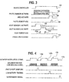
- Graph 100 illustrates one of a plurality of spaced apart active intervals for the control circuits 30. During this interval, the resources of the processor 30a can be devoted to sensor sampling and signal processing.
- graph 102 illustrates a stabilization and sensing interval of photo amplifier 38b, activated via line 38b-1.
- the emitter 36b is activated via drive circuits 38a, line 38a-1 near the end of the stabilization interval. This in turn produces radiant energy R in sample chamber 36a, a portion of which, indicative of smoke, is converted to an electrical signal output via photo amp 38b.
- This signal is sampled, graph 106, and converted to a digital value at the end of the emitter activate interval.
- one of the thermal sensors such as 40a can be activated for a predetermined period of time, graph 108.
- An analog output therefrom, line 40a-2 can be sampled and digitized at the I/O port 30d, signal 110a.
- a second heat or thermal sensor such as sensor 40b can be subsequently activated, graph 112.
- An analog output therefrom, line 40b-2, can be sampled and digitized at the end of the activation interval 112, waveform 110b.
- graph 114 the acquired values from the smoke sensor and the thermal sensors can be processed.
- Fig. 4 illustrates a set of timing diagrams wherein a modulation signal, graph 120, is presented via line 44-3 to an audible output device or sounder.
- graph 120 processor 30a via line 44-1 and voltage increasing circuit for example voltage multiplier circuit 44 can be driven thereby producing on the output line 44-2 a high enough output voltage to properly drive the sounder 48.
- sensor activation and signal processing as illustrated in Fig. 3 can be carried out.
- low battery testing discussed above as well as any supervisory signal generation can be carried out and implemented in any of intervals 120a, 120b or 120c.
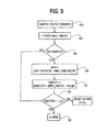
- Fig. 5 is a flow diagram of processing in accordance herewith.
- the processor 30a samples the photo sensor 36c, step 140.
- This sensor output is processed and filtered to produce an adjusted value, for example Min3 processing as described in Tice U.S. Patent No. 5,736,928 , step 142.
- the value of Min3_smoke is updated with every photo sample.
- step 144 the updated Min3_smoke value is used to calculate a running average, Avg step 146.
- the running average is calculated using, for example, a sample size of 256. It will be understood that other numbers of samples could be used without departing from the spirit and scope of the present invention.
- Smooth which represents the short-term increase in Min3_smoke
- step 148 Another value, Smooth, which represents the short-term increase in Min3_smoke, is computed, step 148, by averaging the last two differences between Min3_smoke and corresponding Avg. Smooth is greater than zero when Min3_smoke is increasing. Smooth declines to zero when Min3_smoke remains constant or decreases.
- the most recent value of Smooth is compared with a predetermined value, step 150. When exceeded, an alarm signal is transmitted and an indication is given at the detector step 152.
- the above described steps not only filter out sensor noise, minimizing false alarms, they also carry out sensitivity compensation.
- the processor 30a samples the reading of a heat sensor, such as sensor 40a, graph 108, step 160.
- a value, Avg_temp representing the running average of the last 256 consecutive Inst_temp. including the most recent sample, is calculated, step 162, and stored in memory, step 164.
- Another value, Delta representing the difference between the most recent Inst_t mp and the most recent Avg_temp is calculated step 166a.
- a third value, Avg_delta is calculated step 166b by taking the running average of the last 12 consecutive Deltas and then stored, step 168.
- the current reading is compared to 22 degrees C, step 170. If above 22 degrees C and if Avg_delta is greater than or equal to 4, step 172, then the flag ROR is set step 174.
- step 176i the fixed heat alarm threshold is set to a value that is higher than the most recent Inst_temp by an amount equal to 25% of the difference between the most recent Inst_temp and the predetermined fixed heat alarm threshold step 178. This makes the detector more sensitive by allowing the detector to alarm at a temperature lower than the predetermined fixed heat alarm threshold.
- Avg_delta is less than 4, then the fixed heat alarm threshold will not be reduced.
- the detector in this case will respond at the predetermined fixed heat alarm threshold step 180. This process is repeated for the second heat sensor 40b.
- Avg_delta becomes greater or equal to 4 for one heat sensor
- the fixed heat alarm thresholds for all heat sensors are adjusted.
- the adjustment to heat alarm threshold is only made if the temperature is above 22 °C, i.e. mom temperature, step 170.
- the Avg_temp, and Avg_delta values for each heat sensor are stored individually.
- Inst_temp is also compared to the predetermined heat alarm threshold step 180. When exceeded, an alarm signal is transmitted and an indication is given at the detector, step 182.
- Inst_temp is also compared to a second heat threshold. When exceeded, a trouble signal, different from an alarm signal, is transmitted and an indication is given at the detector.
- smoke sensor output signals and thermal sensor output signals can be processed using a variety of methods without departing from the spirit and scope of the present invention.
- other types of sensors can be incorporated into unit 16i without departing from the spirit and scope of the present invention.
Landscapes
- Engineering & Computer Science (AREA)
- Physics & Mathematics (AREA)
- General Physics & Mathematics (AREA)
- Computer Security & Cryptography (AREA)
- Computer Networks & Wireless Communication (AREA)
- Business, Economics & Management (AREA)
- Emergency Management (AREA)
- Fire Alarms (AREA)
- Fire-Detection Mechanisms (AREA)
Applications Claiming Priority (5)
| Application Number | Priority Date | Filing Date | Title |
|---|---|---|---|
| US19668500P | 2000-04-12 | 2000-04-12 | |
| US09/829,218 US6445292B1 (en) | 2000-04-12 | 2001-04-09 | Processor based wireless detector |
| EP01926838A EP1290650B1 (de) | 2000-04-12 | 2001-04-11 | Prozessorgest tzter drahtloser detektor |
| EP10161378A EP2221789A1 (de) | 2000-04-12 | 2001-04-11 | Prozessorgestützter drahtloser Detektor |
| EP07002940A EP1780685B1 (de) | 2000-04-12 | 2001-04-11 | Prozessorgestützter drahtloser Detektor |
Related Parent Applications (3)
| Application Number | Title | Priority Date | Filing Date |
|---|---|---|---|
| EP01926838.2 Division | 2001-04-11 | ||
| EP07002940.0 Division | 2007-02-12 | ||
| EP10161378.4 Division | 2010-04-28 |
Publications (2)
| Publication Number | Publication Date |
|---|---|
| EP2254100A2 true EP2254100A2 (de) | 2010-11-24 |
| EP2254100A3 EP2254100A3 (de) | 2012-04-04 |
Family
ID=26892126
Family Applications (3)
| Application Number | Title | Priority Date | Filing Date |
|---|---|---|---|
| EP10161378A Withdrawn EP2221789A1 (de) | 2000-04-12 | 2001-04-11 | Prozessorgestützter drahtloser Detektor |
| EP01926838A Revoked EP1290650B1 (de) | 2000-04-12 | 2001-04-11 | Prozessorgest tzter drahtloser detektor |
| EP10174554A Withdrawn EP2254100A3 (de) | 2000-04-12 | 2001-04-11 | Drahtloser Detektor mit einem Prozessor |
Family Applications Before (2)
| Application Number | Title | Priority Date | Filing Date |
|---|---|---|---|
| EP10161378A Withdrawn EP2221789A1 (de) | 2000-04-12 | 2001-04-11 | Prozessorgestützter drahtloser Detektor |
| EP01926838A Revoked EP1290650B1 (de) | 2000-04-12 | 2001-04-11 | Prozessorgest tzter drahtloser detektor |
Country Status (7)
| Country | Link |
|---|---|
| US (1) | US6445292B1 (de) |
| EP (3) | EP2221789A1 (de) |
| AU (2) | AU2001253348B2 (de) |
| CA (1) | CA2405437C (de) |
| DE (2) | DE60142755D1 (de) |
| MX (1) | MXPA02009955A (de) |
| WO (1) | WO2001080194A2 (de) |
Families Citing this family (45)
| Publication number | Priority date | Publication date | Assignee | Title |
|---|---|---|---|---|
| US6445292B1 (en) * | 2000-04-12 | 2002-09-03 | Pittway Corporation | Processor based wireless detector |
| US8144671B2 (en) | 2005-07-01 | 2012-03-27 | Twitchell Jr Robert W | Communicating via nondeterministic and deterministic network routing |
| DE60214310T2 (de) * | 2001-09-21 | 2007-09-13 | Hochiki Corp. | Feuerdetektor |
| US7068177B2 (en) * | 2002-09-19 | 2006-06-27 | Honeywell International, Inc. | Multi-sensor device and methods for fire detection |
| US7119658B2 (en) * | 2003-02-03 | 2006-10-10 | Ingrid, Inc. | Device enrollment in a security system |
| US7042353B2 (en) * | 2003-02-03 | 2006-05-09 | Ingrid, Inc. | Cordless telephone system |
| US7283048B2 (en) | 2003-02-03 | 2007-10-16 | Ingrid, Inc. | Multi-level meshed security network |
| US7532114B2 (en) | 2003-02-03 | 2009-05-12 | Ingrid, Inc. | Fixed part-portable part communications network for a security network |
| US7511614B2 (en) | 2003-02-03 | 2009-03-31 | Ingrid, Inc. | Portable telephone in a security network |
| US7053764B2 (en) * | 2003-02-03 | 2006-05-30 | Ingrid, Inc. | Controller for a security system |
| US7057512B2 (en) * | 2003-02-03 | 2006-06-06 | Ingrid, Inc. | RFID reader for a security system |
| US7079034B2 (en) * | 2003-02-03 | 2006-07-18 | Ingrid, Inc. | RFID transponder for a security system |
| US7079020B2 (en) | 2003-02-03 | 2006-07-18 | Ingrid, Inc. | Multi-controller security network |
| US7495544B2 (en) | 2003-02-03 | 2009-02-24 | Ingrid, Inc. | Component diversity in a RFID security network |
| US7019639B2 (en) * | 2003-02-03 | 2006-03-28 | Ingrid, Inc. | RFID based security network |
| US7091827B2 (en) * | 2003-02-03 | 2006-08-15 | Ingrid, Inc. | Communications control in a security system |
| US7023341B2 (en) * | 2003-02-03 | 2006-04-04 | Ingrid, Inc. | RFID reader for a security network |
| US20040215750A1 (en) * | 2003-04-28 | 2004-10-28 | Stilp Louis A. | Configuration program for a security system |
| US7135161B2 (en) * | 2003-09-04 | 2006-11-14 | University Of Florida Research Foundation, Inc. | Method of producing nanosized oxide powders |
| US20050262923A1 (en) * | 2004-05-27 | 2005-12-01 | Lawrence Kates | Method and apparatus for detecting conditions favorable for growth of fungus |
| US7102505B2 (en) * | 2004-05-27 | 2006-09-05 | Lawrence Kates | Wireless sensor system |
| US7623028B2 (en) * | 2004-05-27 | 2009-11-24 | Lawrence Kates | System and method for high-sensitivity sensor |
| US7218237B2 (en) | 2004-05-27 | 2007-05-15 | Lawrence Kates | Method and apparatus for detecting water leaks |
| US7142107B2 (en) | 2004-05-27 | 2006-11-28 | Lawrence Kates | Wireless sensor unit |
| US7102504B2 (en) * | 2004-05-27 | 2006-09-05 | Lawrence Kates | Wireless sensor monitoring unit |
| US7561057B2 (en) * | 2004-05-27 | 2009-07-14 | Lawrence Kates | Method and apparatus for detecting severity of water leaks |
| US7042352B2 (en) * | 2004-05-27 | 2006-05-09 | Lawrence Kates | Wireless repeater for sensor system |
| US7228726B2 (en) | 2004-09-23 | 2007-06-12 | Lawrence Kates | System and method for utility metering and leak detection |
| EP1803102B1 (de) | 2004-10-18 | 2011-04-06 | Walter Kidde Portable Equipment, Inc. | Frequenzkommunikationsschema in lebenserhaltenden vorrichtungen |
| EP1803105B1 (de) | 2004-10-18 | 2009-12-30 | Walter Kidde Portable Equipment, Inc. | Warnungs-silencing bei niedrigem batteriestand in lebenserhaltenden vorrichtungen |
| EP1803106B1 (de) * | 2004-10-18 | 2010-03-17 | Walter Kidde Portable Equipment, Inc. | Gateway-einrichtung zur verbindung eines systems mit live-safety-einrichtungen |
| US7336168B2 (en) * | 2005-06-06 | 2008-02-26 | Lawrence Kates | System and method for variable threshold sensor |
| US7230528B2 (en) * | 2005-09-20 | 2007-06-12 | Lawrence Kates | Programmed wireless sensor system |
| US7142123B1 (en) | 2005-09-23 | 2006-11-28 | Lawrence Kates | Method and apparatus for detecting moisture in building materials |
| US7528711B2 (en) | 2005-12-19 | 2009-05-05 | Lawrence Kates | Portable monitoring unit |
| US7847700B2 (en) * | 2007-07-03 | 2010-12-07 | Conforti Fred J | System and method for an optical particle detector |
| WO2009140669A2 (en) | 2008-05-16 | 2009-11-19 | Terahop Networks, Inc. | Securing, monitoring and tracking shipping containers |
| CN104106101B (zh) | 2011-07-29 | 2017-03-29 | Adt 美国控股股份有限公司 | 安全系统和方法 |
| US9330550B2 (en) | 2012-07-13 | 2016-05-03 | Walter Kidde Portable Equipment, Inc. | Low nuisance fast response hazard alarm |
| DE102013006378A1 (de) * | 2013-04-13 | 2014-10-16 | Valeo Schalter Und Sensoren Gmbh | Sensoranordnung an einer Lenksäule eines Kraftfahrzeugs |
| US9007224B1 (en) | 2013-10-07 | 2015-04-14 | Google Inc. | Smart-home hazard detector providing non-alarm status signals at opportune moments |
| US9042160B1 (en) * | 2014-07-03 | 2015-05-26 | Sandisk Technologies Inc. | Memory device with resistive random access memory (ReRAM) |
| CN105444915A (zh) * | 2015-11-13 | 2016-03-30 | 苏州扬佛自动化设备有限公司 | 一种高压开关柜监测控制电路 |
| ES2962895T3 (es) * | 2017-06-29 | 2024-03-21 | Vestas Wind Sys As | Proceso de validación de humo para aerogeneradores |
| US11022511B2 (en) | 2018-04-18 | 2021-06-01 | Aron Kain | Sensor commonality platform using multi-discipline adaptable sensors for customizable applications |
Citations (8)
| Publication number | Priority date | Publication date | Assignee | Title |
|---|---|---|---|---|
| US4420746A (en) * | 1979-07-27 | 1983-12-13 | Malinowski William J | Self-calibrating smoke detector and method |
| GB2252191A (en) * | 1991-01-18 | 1992-07-29 | Hochiki Co | Combined method of determining fires |
| EP0803850A1 (de) * | 1996-04-22 | 1997-10-29 | Cerberus Ag | Brandmeldeanlage |
| US5694208A (en) * | 1995-03-24 | 1997-12-02 | Nohmi Bosai Ltd. | Sensor for detecting fine particles such as smoke or dust contained in the air |
| US5736928A (en) | 1995-09-01 | 1998-04-07 | Pittway Corporation | Pre-processor apparatus and method |
| US5914656A (en) * | 1997-04-10 | 1999-06-22 | Nexsys Comtech International, Inc. | Environmental condition detector transmitter interface |
| GB2351170A (en) * | 1999-05-25 | 2000-12-20 | Pittway Corp | Multi-unit monitoring systems |
| EP1290650B1 (de) * | 2000-04-12 | 2007-05-30 | Pittway Corporation | Prozessorgest tzter drahtloser detektor |
Family Cites Families (21)
| Publication number | Priority date | Publication date | Assignee | Title |
|---|---|---|---|---|
| US4300133A (en) * | 1977-03-28 | 1981-11-10 | Solomon Elias E | Smoke detector |
| US4266220A (en) | 1979-07-27 | 1981-05-05 | Malinowski William J | Self-calibrating smoke detector and method |
| US5243698A (en) * | 1982-11-26 | 1993-09-07 | Inmos Limited | Microcomputer |
| US4737770A (en) | 1986-03-10 | 1988-04-12 | Interactive Technologies, Inc. | Security system with programmable sensor and user data input transmitters |
| US4951029A (en) | 1988-02-16 | 1990-08-21 | Interactive Technologies, Inc. | Micro-programmable security system |
| EP0468726B1 (de) * | 1990-07-23 | 1997-01-22 | Nec Corporation | Selektiver Rufempfänger mit einem Sprechgerät und einem LED abwechselnd gesteuert auf Empfang eines Rufs |
| US5065140A (en) | 1991-03-08 | 1991-11-12 | Bell Communications Research, Inc. | Early warning reactive gas detection system |
| US5283549A (en) | 1991-05-31 | 1994-02-01 | Intellitech Industries, Inc. | Infrared sentry with voiced radio dispatched alarms |
| KR950001354B1 (ko) * | 1992-01-27 | 1995-02-17 | 삼성전자주식회사 | 배터리(battery) 단일전원 이동시스템의 기능 제어장치 |
| US5691704A (en) | 1996-01-29 | 1997-11-25 | Engelhard Sensor Technologies, Inc. | Practical and improved fire detector |
| US5543777A (en) | 1993-07-12 | 1996-08-06 | Detection Systems, Inc. | Smoke detector with individual sensitivity calibration and monitoring |
| US5546074A (en) | 1993-08-19 | 1996-08-13 | Sentrol, Inc. | Smoke detector system with self-diagnostic capabilities and replaceable smoke intake canopy |
| US5757267A (en) | 1994-07-29 | 1998-05-26 | Dimango Products | Battery-operated receiver for wireless audible indication system |
| US5757305A (en) | 1994-07-29 | 1998-05-26 | Dimango Products | Transmitter for wireless audible indication system |
| WO1996007165A1 (en) | 1994-08-26 | 1996-03-07 | Sentrol, Inc. | Self-contained, self-adjusting smoke detector and method of operating it |
| US5686885A (en) | 1995-09-28 | 1997-11-11 | Interactive Technologies, Inc. | Sensor test method and apparatus |
| US5726633A (en) | 1995-09-29 | 1998-03-10 | Pittway Corporation | Apparatus and method for discrimination of fire types |
| EP0786777B1 (de) | 1996-01-24 | 2004-03-31 | SGS-THOMSON MICROELECTRONICS S.r.l. | Spannungspegelregler |
| US5990797A (en) * | 1997-03-04 | 1999-11-23 | Bkk Brands, Inc. | Ultraloud smoke detector |
| GB9805488D0 (en) * | 1998-03-13 | 1998-05-13 | Sgs Thomson Microelectronics | Microcomputer |
| US6084522A (en) | 1999-03-29 | 2000-07-04 | Pittway Corp. | Temperature sensing wireless smoke detector |
-
2001
- 2001-04-09 US US09/829,218 patent/US6445292B1/en not_active Expired - Lifetime
- 2001-04-11 EP EP10161378A patent/EP2221789A1/de not_active Withdrawn
- 2001-04-11 AU AU2001253348A patent/AU2001253348B2/en not_active Ceased
- 2001-04-11 EP EP01926838A patent/EP1290650B1/de not_active Revoked
- 2001-04-11 AU AU5334801A patent/AU5334801A/xx active Pending
- 2001-04-11 MX MXPA02009955A patent/MXPA02009955A/es active IP Right Grant
- 2001-04-11 EP EP10174554A patent/EP2254100A3/de not_active Withdrawn
- 2001-04-11 WO PCT/US2001/011721 patent/WO2001080194A2/en not_active Ceased
- 2001-04-11 CA CA002405437A patent/CA2405437C/en not_active Expired - Fee Related
- 2001-04-11 DE DE60142755T patent/DE60142755D1/de not_active Expired - Lifetime
- 2001-04-11 DE DE60128684T patent/DE60128684T2/de not_active Revoked
Patent Citations (8)
| Publication number | Priority date | Publication date | Assignee | Title |
|---|---|---|---|---|
| US4420746A (en) * | 1979-07-27 | 1983-12-13 | Malinowski William J | Self-calibrating smoke detector and method |
| GB2252191A (en) * | 1991-01-18 | 1992-07-29 | Hochiki Co | Combined method of determining fires |
| US5694208A (en) * | 1995-03-24 | 1997-12-02 | Nohmi Bosai Ltd. | Sensor for detecting fine particles such as smoke or dust contained in the air |
| US5736928A (en) | 1995-09-01 | 1998-04-07 | Pittway Corporation | Pre-processor apparatus and method |
| EP0803850A1 (de) * | 1996-04-22 | 1997-10-29 | Cerberus Ag | Brandmeldeanlage |
| US5914656A (en) * | 1997-04-10 | 1999-06-22 | Nexsys Comtech International, Inc. | Environmental condition detector transmitter interface |
| GB2351170A (en) * | 1999-05-25 | 2000-12-20 | Pittway Corp | Multi-unit monitoring systems |
| EP1290650B1 (de) * | 2000-04-12 | 2007-05-30 | Pittway Corporation | Prozessorgest tzter drahtloser detektor |
Also Published As
| Publication number | Publication date |
|---|---|
| DE60142755D1 (de) | 2010-09-16 |
| AU2001253348B2 (en) | 2006-03-16 |
| DE60128684T2 (de) | 2008-01-24 |
| EP2221789A1 (de) | 2010-08-25 |
| WO2001080194A2 (en) | 2001-10-25 |
| EP1290650B1 (de) | 2007-05-30 |
| US6445292B1 (en) | 2002-09-03 |
| EP1290650A4 (de) | 2005-11-09 |
| EP2254100A3 (de) | 2012-04-04 |
| WO2001080194A3 (en) | 2002-02-21 |
| CA2405437A1 (en) | 2001-10-25 |
| MXPA02009955A (es) | 2003-02-12 |
| AU5334801A (en) | 2001-10-30 |
| US20020021223A1 (en) | 2002-02-21 |
| DE60128684D1 (de) | 2007-07-12 |
| EP1290650A2 (de) | 2003-03-12 |
| CA2405437C (en) | 2009-08-04 |
Similar Documents
| Publication | Publication Date | Title |
|---|---|---|
| EP1290650B1 (de) | Prozessorgest tzter drahtloser detektor | |
| AU2001253348A1 (en) | Processor based wireless detector | |
| US7602304B2 (en) | Multi-sensor device and methods for fire detection | |
| JP3724689B2 (ja) | 火災監視装置及び火災感知器 | |
| US9761124B2 (en) | Multiple procesor hazard detection system | |
| US7446647B2 (en) | State validation using bi-directional wireless link | |
| US9892621B2 (en) | Systems and methods for intelligent alarming | |
| US6320501B1 (en) | Multiple sensor system for alarm determination with device-to-device communications | |
| US20160232781A1 (en) | Systems and methods for compensating for sensor drift in a hazard detection system | |
| EP1006500A2 (de) | Rauchmelder mit Absaugeinheit und Durchflussmesser | |
| US5864286A (en) | Distributed intelligence alarm system having a two- tier monitoring process for detecting alarm conditions | |
| US6762688B2 (en) | Device with silencing circuitry | |
| RU96120082A (ru) | Внепультовый датчик для запоминания информации | |
| EP1780685B1 (de) | Prozessorgestützter drahtloser Detektor | |
| JP2018136808A (ja) | 煙感知器 | |
| JP2583271B2 (ja) | 火災警報装置 | |
| JPH10282245A (ja) | 超音波を用いた動体検出方式および装置 | |
| JPH09147253A (ja) | ワイヤレス送信器 | |
| JPH0441435Y2 (de) | ||
| KR20100064358A (ko) | 통신 시스템 | |
| KR950004025A (ko) | 환경감시용 유.무선 제어장치 |
Legal Events
| Date | Code | Title | Description |
|---|---|---|---|
| PUAI | Public reference made under article 153(3) epc to a published international application that has entered the european phase |
Free format text: ORIGINAL CODE: 0009012 |
|
| AC | Divisional application: reference to earlier application |
Ref document number: 1290650 Country of ref document: EP Kind code of ref document: P Ref document number: 2221789 Country of ref document: EP Kind code of ref document: P Ref document number: 1780685 Country of ref document: EP Kind code of ref document: P |
|
| AK | Designated contracting states |
Kind code of ref document: A2 Designated state(s): DE FR GB |
|
| PUAL | Search report despatched |
Free format text: ORIGINAL CODE: 0009013 |
|
| AK | Designated contracting states |
Kind code of ref document: A3 Designated state(s): DE FR GB |
|
| RIC1 | Information provided on ipc code assigned before grant |
Ipc: G08B 29/18 20060101ALI20120229BHEP Ipc: G08B 25/10 20060101AFI20120229BHEP |
|
| 17P | Request for examination filed |
Effective date: 20121001 |
|
| 17Q | First examination report despatched |
Effective date: 20121126 |
|
| STAA | Information on the status of an ep patent application or granted ep patent |
Free format text: STATUS: THE APPLICATION IS DEEMED TO BE WITHDRAWN |
|
| 18D | Application deemed to be withdrawn |
Effective date: 20130409 |